EP3057808B1 - Austragseinrichtung für granulat - Google Patents
Austragseinrichtung für granulat Download PDFInfo
- Publication number
- EP3057808B1 EP3057808B1 EP14784453.4A EP14784453A EP3057808B1 EP 3057808 B1 EP3057808 B1 EP 3057808B1 EP 14784453 A EP14784453 A EP 14784453A EP 3057808 B1 EP3057808 B1 EP 3057808B1
- Authority
- EP
- European Patent Office
- Prior art keywords
- discharge device
- star feeder
- granules
- wear
- vanes
- Prior art date
- Legal status (The legal status is an assumption and is not a legal conclusion. Google has not performed a legal analysis and makes no representation as to the accuracy of the status listed.)
- Active
Links
Images



Classifications
-
- B—PERFORMING OPERATIONS; TRANSPORTING
- B61—RAILWAYS
- B61C—LOCOMOTIVES; MOTOR RAILCARS
- B61C15/00—Maintaining or augmenting the starting or braking power by auxiliary devices and measures; Preventing wheel slippage; Controlling distribution of tractive effort between driving wheels
- B61C15/08—Preventing wheel slippage
- B61C15/10—Preventing wheel slippage by depositing sand or like friction increasing materials
- B61C15/105—Preventing wheel slippage by depositing sand or like friction increasing materials with gravity activated sanding equipment
-
- B—PERFORMING OPERATIONS; TRANSPORTING
- B60—VEHICLES IN GENERAL
- B60B—VEHICLE WHEELS; CASTORS; AXLES FOR WHEELS OR CASTORS; INCREASING WHEEL ADHESION
- B60B39/00—Increasing wheel adhesion
- B60B39/02—Vehicle fittings for scattering or dispensing material in front of its wheels
- B60B39/04—Vehicle fittings for scattering or dispensing material in front of its wheels the material being granular, e.g. sand
-
- B—PERFORMING OPERATIONS; TRANSPORTING
- B60—VEHICLES IN GENERAL
- B60B—VEHICLE WHEELS; CASTORS; AXLES FOR WHEELS OR CASTORS; INCREASING WHEEL ADHESION
- B60B39/00—Increasing wheel adhesion
- B60B39/02—Vehicle fittings for scattering or dispensing material in front of its wheels
- B60B39/04—Vehicle fittings for scattering or dispensing material in front of its wheels the material being granular, e.g. sand
- B60B39/06—Vehicle fittings for scattering or dispensing material in front of its wheels the material being granular, e.g. sand the dispensing being effected by mechanical means
-
- B—PERFORMING OPERATIONS; TRANSPORTING
- B61—RAILWAYS
- B61C—LOCOMOTIVES; MOTOR RAILCARS
- B61C15/00—Maintaining or augmenting the starting or braking power by auxiliary devices and measures; Preventing wheel slippage; Controlling distribution of tractive effort between driving wheels
- B61C15/08—Preventing wheel slippage
- B61C15/10—Preventing wheel slippage by depositing sand or like friction increasing materials
-
- B—PERFORMING OPERATIONS; TRANSPORTING
- B65—CONVEYING; PACKING; STORING; HANDLING THIN OR FILAMENTARY MATERIAL
- B65G—TRANSPORT OR STORAGE DEVICES, e.g. CONVEYORS FOR LOADING OR TIPPING, SHOP CONVEYOR SYSTEMS OR PNEUMATIC TUBE CONVEYORS
- B65G53/00—Conveying materials in bulk through troughs, pipes or tubes by floating the materials or by flow of gas, liquid or foam
- B65G53/34—Details
- B65G53/40—Feeding or discharging devices
- B65G53/46—Gates or sluices, e.g. rotary wheels
-
- B—PERFORMING OPERATIONS; TRANSPORTING
- B65—CONVEYING; PACKING; STORING; HANDLING THIN OR FILAMENTARY MATERIAL
- B65G—TRANSPORT OR STORAGE DEVICES, e.g. CONVEYORS FOR LOADING OR TIPPING, SHOP CONVEYOR SYSTEMS OR PNEUMATIC TUBE CONVEYORS
- B65G53/00—Conveying materials in bulk through troughs, pipes or tubes by floating the materials or by flow of gas, liquid or foam
- B65G53/34—Details
- B65G53/40—Feeding or discharging devices
- B65G53/46—Gates or sluices, e.g. rotary wheels
- B65G53/4608—Turnable elements, e.g. rotary wheels with pockets or passages for material
- B65G53/4616—Turnable elements, e.g. rotary wheels with pockets or passages for material with axis of turning parallel to flow
-
- B—PERFORMING OPERATIONS; TRANSPORTING
- B60—VEHICLES IN GENERAL
- B60B—VEHICLE WHEELS; CASTORS; AXLES FOR WHEELS OR CASTORS; INCREASING WHEEL ADHESION
- B60B2360/00—Materials; Physical forms thereof
- B60B2360/30—Synthetic materials
- B60B2360/32—Plastic compositions
- B60B2360/324—Comprising polyurethane
-
- B—PERFORMING OPERATIONS; TRANSPORTING
- B60—VEHICLES IN GENERAL
- B60B—VEHICLE WHEELS; CASTORS; AXLES FOR WHEELS OR CASTORS; INCREASING WHEEL ADHESION
- B60B2900/00—Purpose of invention
- B60B2900/10—Reduction of
- B60B2900/121—Resisting forces
- B60B2900/1212—Resisting forces due to friction
-
- B—PERFORMING OPERATIONS; TRANSPORTING
- B60—VEHICLES IN GENERAL
- B60B—VEHICLE WHEELS; CASTORS; AXLES FOR WHEELS OR CASTORS; INCREASING WHEEL ADHESION
- B60B2900/00—Purpose of invention
- B60B2900/30—Increase in
- B60B2900/321—Lifetime
-
- B—PERFORMING OPERATIONS; TRANSPORTING
- B60—VEHICLES IN GENERAL
- B60B—VEHICLE WHEELS; CASTORS; AXLES FOR WHEELS OR CASTORS; INCREASING WHEEL ADHESION
- B60B2900/00—Purpose of invention
- B60B2900/50—Improvement of
- B60B2900/541—Servicing
Definitions
- the invention relates to a discharge device for granules, comprising a housing with at least one inlet opening for the granules, with a motor connected to a motor rotating about a vertical axis of rotation, cellular with multiple wings and chambers arranged therebetween, in which chambers the granules upon rotation of the cell wheel from the at least one inlet opening to at least one outlet is conveyed.
- granules is a granular to powdery, easily pourable solid to understand, for example, grit or debris, as it is used to improve the braking effect between the wheels of vehicles and the road.
- granules or sand from a container via a metering and conveying via a nozzle in front of the rail wheels in the gap between the rail wheel and rail promoted to increase the frictional resistance between rail wheel and rail and to reduce the braking distance.
- this describes AT 505 783 B1 Such a spreader, wherein the dosage of the grit is made via a rotary feeder.
- Another spreader in which the metering and promotion of the grit is done with compressed air, is for example from the WO 2008/064747 A1 known.
- the DE 195 011 179 A1 relates to a dispensing device for granules of the subject type, which, however, is relatively large in construction and has no measures for improving the wear properties.
- the DE 26 064 83 A1 describes a device for conveying wood chips, as well as powdery or paste-like or pasty substances in which the dosage of the funded material does not matter.
- the US 5,795,108 A relates to a device for conveying granules, in particular sand, and for uniform distribution of the same, for example on golf courses, where it does not depend on a precise dosage of the material.
- the object of the present invention is therefore to provide an above-mentioned discharge device for granules, which is characterized by a low wear, an increased service life and thus extended maintenance intervals. Disadvantages of existing discharge in terms of wear to be reduced or prevented.
- the object of the invention is achieved in that the housing is designed for placement within a container for the granules, the at least one inlet opening is arranged laterally obliquely downward on the housing, and the cell within a substantially cylindrical wear bushing and the at least one outlet on the Bottom of the wear bush is arranged.
- the at least one outlet on the underside of the wear bushing results in particularly advantageous paths of the granulate from the container of the granulate to the at least one outlet and thus to a relatively short residence time of the granulate within the discharge device or the cellular wheel, which in turn leads to low wear leads.
- the wear properties can be improved because the granules trickles by gravity substantially in the cells of the cell wheel and is conveyed upon rotation of the cell wheel to the at least one outlet.
- a vertical axis rotary feeder can be more easily assembled and disassembled, reducing maintenance time and maintenance costs. Due to the arrangement of the discharge within the container for the granules on the one hand, the height of the granule container and the discharge and the possible conveyor can be kept low and the maintenance can be facilitated because the discharge can be disassembled from below from the granules and in turn mounted.
- the arrangement of the discharge in the granule container optimal protection against external influences is achieved in a simple manner and thus unwanted spurious potentials and thus system failures are effectively avoided.
- the gravity is optimally utilized by the granules can trickle without help from the container in the at least one inlet opening. From the inlet openings arranged laterally on the housing, the granules pass directly into the chambers between the blades of the cellular wheel and are transported upon rotation of the cellular wheel and then reach the at least one correspondingly arranged outlet for further transport of the granules.
- the wear bushing which can be formed of suitable material, is easily and quickly replaceable without having to replace the entire discharge device. Due to the substantially vertical arrangement of the wear bush removal and installation of the bottom of the discharge is easy and quick.
- the at least one outlet is slit-shaped or sector-shaped, further advantages result. In a sector-shaped design of the outlet, this extends over at least one or more chambers between the wings of the cell wheel. After the at least one outlet, the granules can be conveyed in different ways to the desired destination, for example by mechanical or pneumatic conveying.
- the bucket has at least eight wings. This results in at least eight chambers between the blades of the cell wheel, within which the granules are transported.
- blades of the bucket are scoop-like, further optimization of the transport of the pellets by means of the bucket wheel to the at least one outlet can take place and the friction of the pellets on the vanes of the bucket wheel can be reduced.
- the blades of the cell wheel are arranged obliquely to the direction of the axis of rotation, a further optimization of the transport of the granules can be achieved. Due to the oblique arrangement of the wings, in contrast to a straight arrangement of the wings, a horizontal and a vertical direction of force sets. In particular, the vertical force component leads to a targeted promotion of the granules down, whereby a more intensive Granulataustrag can be achieved.
- two opposite inlet openings are provided on the housing.
- the conveyed amount of granules can be increased at a constant rotational speed of the cell wheel or the rotational speed of the cell wheel can be correspondingly reduced with the same amount of granulated material conveyed.
- the paths of the granulate within the discharge device between inlet opening and outlet can be reduced and thus the wear can also be reduced.
- Optimal flow or flow conditions for the granules are given when the inlet openings are arranged at an angle of 30 to 40 ° to the horizontal obliquely downward. It is advantageous if the bottom of the granule container is already arranged obliquely in a similar manner and merges into the corresponding obliquely arranged inlet openings of the discharge.
- the motor is arranged above the cellular wheel, the assembly and disassembly of wearing parts of the discharge device can be facilitated.
- a device for conveying the granules On the underside of the housing fastening elements for fixing a device for conveying the granules are provided, which conveying device can be designed in various ways. Depending on the application, mechanical or pneumatic conveyors are mainly used.
- the wear bush is displaceable relative to the cellular wheel in the direction of the axis of rotation of the cellular wheel. As a result, a compensation of the wear or readjustment of the discharge device can be achieved and the service life can be increased and the maintenance intervals extended.
- This readjustment can be effected, for example, by the wear bush being displaceably mounted in the direction of the cellular wheel via at least one spring. Due to the spring-supported sliding bearing of the wear bushing, wear on the wear bushing and / or the cellular wheel can be compensated to a certain extent and thus the service life of the discharge device can be extended.
- the bucket also be slidably mounted together with the motor via at least one spring in the direction of the wear bushing.
- the at least one spring thus presses the feeder against the wear bush and thus compensates for wear to a certain extent.
- the blades of the cellular wheel are arranged obliquely at the bottom in the direction of the axis of rotation of the cellular wheel, and the underside of the wear bushing is funnel-shaped complementary to the blades of the cellular wheel.
- the cellular wheel made of plastic, preferably made of polyurethane.
- Plastic is relatively cheap and has good corrosion resistance.
- Ultra-high molecular weight polyethylene has particularly good wear properties.
- one of the two components should be resilient to the other component and therefore preferably formed by plastic.
- the wear bush can also be made of plastic, preferably of ultra-high molecular weight polyethylene.
- Fig. 1 shows a variant of a discharge device 1 in a vertically sectioned view.
- the discharge device 1 is arranged within a container 12 for the granules 2.
- the discharge device 1 comprises a housing 3 with at least one inlet opening 4 for the granules 2 and a cellular wheel 6, which is connected to a motor 11.
- the cellular wheel 6 has a plurality of vanes 7 and interposed chambers 9, in which the granules 2 is conveyed upon rotation of the cellular wheel 6 from the at least one inlet opening 4 to at least one outlet 5.
- the wings 7 and 9 chambers of the cellular wheel 6 are from the sectional drawing according to Fig. 2 better visible.
- the axis of rotation 8 of the cellular wheel 6 is arranged substantially vertically, so that by utilizing gravity, the granules 2 can reach the chambers 9 of the cellular wheel 6 via the at least one inlet opening 4 and is conveyed to the at least one outlet 5 when the cellular wheel 6 rotates.
- the paths of the granules 2 within the discharge device 1 are low and the residence time of the granules 2 in the discharge 1 short, whereby the wear, in particular of the cellular wheel 6, can be kept low.
- the cellular wheel 6 is arranged within a substantially cylindrical wear bushing 10.
- the wear bushing 10 and the cellular wheel 6 are characterized in the subject construction by a long service life and long maintenance intervals. Should they still need to be replaced, they are simply interchangeable from the bottom of the container 12 for the granules 2.
- the feeder 6 has at least eight wings 7 and thus eight chambers 9.
- the inlet openings 4 are arranged laterally on the housing 3 of the discharge device 1 and arranged as the bottom of the container 12 for the granules 2 inclined.
- the at least one outlet 5 of the discharge device 1 is arranged on the underside of the wear bushing 10 and is preferably slot-shaped, as described Fig. 2 recognizable.
- the wear bushing 10 according to the invention with respect to the cellular wheel 6 in the direction of the axis of rotation 8 of the cellular wheel 6 is slidably formed.
- a readjustment of the wear bushing 10 with respect to the cellular wheel 6 to a certain extent, for example, a few millimeters, done and thus increases the service life of the discharge device 1 and the maintenance intervals are extended.
- the cellular wheel 6 is preferably made of plastic, preferably polyurethane, whereas the wear bushing 10 is also formed made of plastic, preferably of ultra-high molecular weight polyethylene.
- the housing 3 of the discharge device 1 is preferably made of corrosion-resistant, lightweight metal, for example aluminum or an aluminum alloy.
- the motor 11 for driving the cellular wheel 6, which is preferably arranged above the cellular wheel 6 to facilitate the assembly and disassembly of the cellular wheel 6, may be formed by a DC geared motor.
- the outlet 5 is not slot-shaped but sector-shaped and comprises, for example, 3 chambers 9 between the wings 7 of the cellular wheel 6.
- the feed for the granules 2 also differently, for example, the inlet opening horizontally and the outlet vertically be arranged next to the cellular wheel (not shown).
- Such a variant has advantages in terms of a smaller size of the discharge.
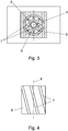
- Fig. 4 shows a variant of an embodiment of the cellular wheel 6 in side view, wherein the wings 7 are arranged obliquely to the direction of the axis of rotation 8.
- the wings 7 are arranged obliquely to the direction of the axis of rotation 8.
- the vertical force component leads to a targeted promotion of the granules 2 down towards the outlet 5, whereby a more intensive granulate discharge can be achieved.
- Fig. 5 and Fig. 6 show a further variant of a discharge device 1 in vertical and horizontal sectional view, with respect to the variant according to the Figures 1 and 2 changed wear tracking.
- the wear bush 10 is not biased in the direction of feeder 6, but the cellular 6 pressed together with the motor 11 via at least one spring 15 against the wear bushing 10. Also in this way a readjustment or wear compensation can take place. Otherwise, the components are essentially identical to those in the Fig. 1 and 2 formed trained.
- the fasteners for attachment of the motor within the housing 3 may be arranged in corresponding oblong holes, which allow a displacement in the direction of the axis of rotation 8 by a few millimeters.
- FIG. 7 a schematic block diagram of a use of the discharge device 1 shown in a sand dispenser.
- the discharge device 1 is arranged in the container 12 for the granules 2 and connected to a corresponding control device 16.
- the control device 16 controls the rotational speed of the cellular wheel 6 in the discharge device 1 and thus the amount of granules, as it is forwarded to the conveyor 14, which is arranged below the discharge.
- the conveyor 14 for conveying the granules 2 is formed by a pneumatic conveyor.
- compressed air is introduced from a compressed air source 17 via a compressed air line 18 in the conveyor 14 and the granules, which trickles down from the discharge 1 via the at least one outlet 5, via a feed line 19 to the desired location, for example in front of the rail wheel of a Rail vehicle, transported.
- the present invention is characterized by optimum wear properties, without the construction of the discharge would be particularly complex or expensive.
Landscapes
- Engineering & Computer Science (AREA)
- Mechanical Engineering (AREA)
- Transportation (AREA)
- Filling Or Emptying Of Bunkers, Hoppers, And Tanks (AREA)
Description
- Die Erfindung betrifft eine Austragseinrichtung für Granulat, mit einem Gehäuse mit zumindest einer Zulauföffnung für das Granulat, mit einem mit einem Motor verbundenen, um eine vertikale Drehachse rotierenden, Zellenrad mit mehreren Flügeln und dazwischen angeordneten Kammern, in welchen Kammern das Granulat bei Drehung des Zellenrades von der zumindest einen Zulauföffnung zu zumindest einem Auslass beförderbar ist.
- Unter dem Begriff "Granulat" ist ein körniger bis pulverförmiger, leicht schüttbarer Feststoff zu verstehen, beispielsweise Streugut oder Streusand, wie er zur Verbesserung der Bremswirkung zwischen den Rädern von Fahrzeugen und der Fahrbahn eingesetzt wird. Beispielsweise wird bei Schienenfahrzeugen Granulat bzw. Sand von einem Behälter über eine Dosier- und Fördereinrichtung über eine Düse vor den Schienenrädern in den Spalt zwischen Schienenrad und Schiene befördert, um den Reibungswiderstand zwischen Schienenrad und Schiene zu erhöhen und den Bremsweg zu verringern.
- Beispielsweise beschreibt die
AT 505 783 B1 - Ein anderes Streugerät, bei dem die Dosierung und Förderung des Streuguts mit Druckluft erfolgt, ist beispielsweise aus der
WO 2008/064747 A1 bekannt geworden. - Die
DE 195 011 179 A1 betrifft eine Austragseinrichtung für Granulat der gegenständlichen Art, welche jedoch relativ groß in ihrem Aufbau ist und keine Maßnahmen für eine Verbesserung der Verschleißeigenschaften aufweist. - Die
DE 26 064 83 A1 beschreibt eine Einrichtung zum Fördern von Holzspänen, sowie pulver- oder pastenartige oder pastöse Stoffe, bei der die Dosierung des geförderten Materials keine Rolle spielt. - Die
US 5,795,108 A betrifft eine Vorrichtung zur Förderung eines Granulats, insbesondere Sand, und zur gleichmäßigen Verteilung desselben, beispielsweise auf Golfplätzen, wo es auf eine genau Dosierung des Materials nicht ankommt. - Insbesondere bei der Verwendung relativ hartem Granulats, beispielsweise von Quarzsand, besteht das Problem eines relativ raschen Verschleißes von Komponenten der Austragseinrichtung, da das Granulat bzw. der Sand durch die Reibung an den Komponenten der Austragseinrichtung zu einer raschen Verschlechterung der Austragsfunktion oder sogar zu einer Fehlfunktion führt. Durch Verwendung von sehr hochwertigen und beständigen Materialien für die Komponenten der Austragseinrichtung konnten keine wesentlichen Verbesserungen erzielt werden, da es dabei zu Blockaden kommen kann, wenn das harte Granulat mit bewegten Teilen der Austragseinrichtung aus ebenfalls hartem Material zusammentreffen. Bessere Ergebnisse konnten daher bei Verwendung von weicheren, allerdings auch weniger widerstandsfähigen Materialien, insbesondere für die bewegten Teile der Austragseinrichtung, erzielt werden. Beispielsweise werden Zellenräder häufig aus Kunststoff hergestellt, wodurch jedoch die Lebensdauer erheblich reduziert wird. Der Austausch der Verschleißteile verursacht jedoch Standzeiten und Montagekosten, welche meist unerwünscht sind. Insbesondere bei Streugeräten, wie sie bei Schienenfahrzeugen häufig eingesetzt werden, sind niedrige Standzeiten und kurze Wartungsintervalle nicht erwünscht.
- Die Aufgabe der vorliegenden Erfindung besteht daher in der Schaffung einer oben genannten Austragseinrichtung für Granulat, welche durch einen niedrigen Verschleiß, eine erhöhte Standzeit und somit verlängerte Wartungsintervalle ausgezeichnet wird. Nachteile bestehender Austragseinrichtungen in Bezug auf den Verschleiß sollen reduziert oder verhindert werden.
- Gelöst wird die erfindungsgemäße Aufgabe dadurch, dass das Gehäuse zur Anordnung innerhalb eines Behälters für das Granulat ausgebildet ist, die zumindest eine Zulauföffnung seitlich am Gehäuse schräg abwärts verlaufend angeordnet ist, und das Zellenrad innerhalb einer im Wesentlichen zylinderförmigen Verschleißbuchse und der zumindest eine Auslass an der Unterseite der Verschleißbuchse angeordnet ist. Durch den zumindest einen Auslass an der Unterseite der Verschleißbuchse ergeben sich besonders vorteilhafte Wege des Granulats vom Behälter des Granulats bis zu dem zumindest einen Auslass und somit zu einer relativ geringen Verweildauer des Granulats innerhalb der Austragseinrichtung bzw. des Zellenrades, was wiederum zu einem geringen Verschleiß führt. Durch die vertikale Anordnung der Drehachse des Zellenrades können die Verschleißeigenschaften verbessert werden, da das Granulat durch die Schwerkraft im Wesentlichen in die Zellen des Zellenrades rieselt und bei Drehung des Zellenrades zu dem zumindest einen Auslass befördert wird. Zusätzlich kann ein Zellenrad mit vertikaler Drehachse leichter montiert und demontiert werden, sodass die Wartungsdauer und auch die Wartungskosten reduziert werden können. Durch die Anordnung der Austragseinrichtung innerhalb des Behälters für das Granulat kann einerseits die Bauhöhe des Granulatbehälters und der Austragseinrichtung sowie der allfälligen Fördereinrichtung gering gehalten werden und die Wartung erleichtert werden, da die Austragseinrichtung von unten aus dem Granulatbehälter demontiert und wiederum montiert werden kann. Durch die Anordnung der Austragseinrichtung im Granulatbehälter wird auch auf einfache Weise ein optimaler Schutz gegen äußere Einflüsse erreicht und werden somit ungewollte Störpotenziale und somit Systemausfälle wirksam vermieden. Zusätzlich wird die Schwerkraft optimal ausgenutzt, indem das Granulat ohne Hilfe vom Behälter in die zumindest eine Zulauföffnung rieseln kann. Von den seitlich am Gehäuse angeordneten Zulauföffnungen gelangt das Granulat direkt in die Kammern zwischen den Flügeln des Zellenrades und wird bei Drehung des Zellenrades transportiert und gelangt dann zu dem zumindest einen entsprechend angeordneten Auslass zur weiteren Beförderung des Granulats. Die Verschleißbuchse, welche aus geeignetem Material gebildet werden kann, ist einfach und rasch austauschbar, ohne dass die gesamte Austragseinrichtung ersetzt werden muss. Durch die im Wesentlichen vertikale Anordnung der Verschleißbuchse ist ein Ausbau und Einbau von der Unterseite der Austragseinrichtung einfach und rasch möglich.
- Wenn der zumindest eine Auslass schlitzförmig oder sektorförmig ausgebildet ist, ergeben sich weitere Vorteile. Bei einer sektorförmigen Ausbildung des Auslasses erstreckt sich dieser über zumindest eine oder mehrere Kammern zwischen den Flügeln des Zellenrades. Nach dem zumindest einen Auslass kann das Granulat auf unterschiedliche Weise zu dem gewünschten Ziel befördert werden, beispielsweise durch eine mechanische oder pneumatische Förderung.
- Idealerweise weist das Zellenrad mindestens acht Flügel auf. Dadurch resultieren mindestens acht Kammern zwischen den Flügeln des Zellenrades, innerhalb welcher das Granulat befördert wird. Je mehr Flügel bzw. dazwischen angeordnete Kammern das Zellenrad aufweist, desto geringer ist im Wesentlichen die Verweildauer des Granulats innerhalb des Zellenrades und somit der Verschleiß des Zellenrades bzw. der das Zellenrad umgebenden Verschleißbuchse.
- Wenn die Flügel des Zellenrades schaufelartig ausgebildet sind, kann eine weitere Optimierung des Transports des Granulats mithilfe des Zellenrades zu dem zumindest einen Auslass stattfinden und die Reibung des Granulats an den Flügeln des Zellenrades reduziert werden.
- Wenn die Flügel des Zellenrades schräg zur Richtung der Drehachse angeordnet sind, kann eine weitere Optimierung des Transports des Granulats erreicht werden. Durch die schräge Anordnung der Flügel stellt sich im Unterschied zu einer geraden Anordnung der Flügel eine horizontale und eine vertikale Kraftrichtung ein. Besonders die vertikale Kraftkomponente führt zu einer gezielten Förderung des Granulats nach unten, wodurch ein intensiverer Granulataustrag erreicht werden kann.
- Vorteilhafterweise sind zwei gegenüberliegende Zulauföffnungen am Gehäuse vorgesehen. Dadurch kann die geförderte Menge an Granulat bei gleichbleibender Drehgeschwindigkeit des Zellenrades erhöht oder die Drehgeschwindigkeit des Zellenrades bei gleicher geförderter Granulatmenge entsprechend verringert werden. Zudem können bei zwei oder mehr Zulauföffnungen die Wege des Granulats innerhalb der Austragseinrichtung zwischen Zulauföffnung und Auslass reduziert und somit der Verschleiß ebenfalls verringert werden.
- Optimale Riesel- oder Fließbedingungen für das Granulat sind dann gegeben, wenn die Zulauföffnungen in einem Winkel von 30 bis 40° zur Horizontalen schräg abwärts verlaufend angeordnet sind. Dabei ist es von Vorteil, wenn die Unterseite des Granulatbehälters bereits in einer ähnlichen Weise schräg angeordnet ist und in die entsprechend schräg angeordneten Zulauföffnungen der Austragseinrichtungen übergeht.
- Wenn der Motor über dem Zellenrad angeordnet ist, kann die Montage und Demontage von Verschleißteilen der Austragseinrichtung erleichtert werden.
- An der Unterseite des Gehäuses sind Befestigungselemente zur Befestigung einer Einrichtung zur Förderung des Granulats vorgesehen, welche Förderungseinrichtung verschiedenartig ausgebildet sein kann. Je nach Anwendung kommen mechanische oder pneumatische Fördereinrichtungen hauptsächlich zum Einsatz.
- Von Vorteil ist weiters, wenn die Verschleißbuchse gegenüber dem Zellenrad in Richtung der Drehachse des Zellenrades verschiebbar ist. Dadurch kann eine Kompensation des Verschleißes bzw. eine Nachjustierung der Austragseinrichtung erzielt werden und die Standzeit erhöht und die Wartungsintervalle verlängert werden.
- Diese Nachjustierung kann beispielsweise dadurch erfolgen, dass die Verschleißbuchse über zumindest eine Feder in Richtung Zellenrad verschiebbar gelagert ist. Durch die federunterstützte verschiebbare Lagerung der Verschleißbuchse kann ein Abrieb an der Verschleißbuchse und bzw. oder dem Zellenrad bis zu einem gewissen Grad ausgeglichen und somit die Standzeit der Austragseinrichtung verlängert werden.
- Alternativ dazu kann auch das Zellenrad gemeinsam mit dem Motor über zumindest eine Feder in Richtung der Verschleißbuchse verschieblich gelagert sein. Die zumindest eine Feder presst somit das Zellenrad gegen die Verschleißbuchse und gleicht somit einen Verschleiß bis zu einem gewissen Grad aus.
- Gemäß einem weiteren Merkmal der Erfindung sind die Flügel des Zellenrades an der Unterseite in Richtung der Drehachse des Zellenrades schräg verlaufend angeordnet, und die Unterseite der Verschleißbuchse komplementär zu den Flügeln des Zellenrades trichterförmig ausgebildet. Dadurch wird die Förderung des Granulats innerhalb der Austragseinrichtung noch weiter unterstützt und der Verschleiß durch Reibung des Granulats an den Komponenten der Austragseinrichtung reduziert.
- Vorteilhafterweise ist das Zellenrad aus Kunststoff, vorzugsweise aus Polyurethan, gebildet. Kunststoff ist relativ billig und weist gute Korrosionsbeständigkeit auf. Ultrahochmolekulares Polyethylen weist besonders gute Verschleißeigenschaften auf. Theoretisch sind für das Zellenrad und die Verschleißbuchse auch metallische Materialien denkbar. Eine der beiden Komponenten sollte jedoch gegenüber der anderen Komponente nachgiebig sein und daher vorzugsweise durch Kunststoff gebildet sein.
- Die Verschleißbuchse kann ebenfalls aus Kunststoff, vorzugsweise aus ultrahochmolekularem Polyethylen, gebildet sein.
- Die Erfindung wird anhand der beigefügten Zeichnungen näher erläutert. Darin zeigen:
- Fig. 1
- eine Variante einer Austragseinrichtung in vertikal geschnittener Ansicht;
- Fig. 2
- die Austragseinrichtung gemäß
Fig. 1 entlang der Schnittlinie II - II; - Fig. 3
- die Austragseinrichtung gemäß
Fig. 1 entlang der Schnittlinie II - II in einer abgewandelten Form; - Fig. 4
- eine Variante einer Ausführungsform des Zellenrades in Seitenansicht;
- Fig. 5
- eine weitere Variante einer Austragseinrichtung in vertikal geschnittener Ansicht;
- Fig. 6
- die Austragseinrichtung gemäß
Fig. 5 entlang der Schnittlinie VI - VI; und - Fig. 7
- ein schematisches Blockschaltbild einer Verwendung der Austragseinrichtung in einer Sandstreueinrichtung.
-
Fig. 1 zeigt eine Variante einer Austragseinrichtung 1 in vertikal geschnittener Ansicht. Die Austragseinrichtung 1 ist innerhalb einem Behälters 12 für das Granulat 2 angeordnet. Durch eine vertikale Einbaulage der Austragseinrichtung 1 im Behälter 12 für das Granulat 2 wird auf einfache Weise ein optimaler Schutz der Austragseinrichtung 1 gegen äußere Einflüsse erreicht und werden somit ungewollte Störpotenziale und somit Systemausfälle wirksam vermieden. Die Austragseinrichtung 1 umfasst ein Gehäuse 3 mit zumindest einer Zulauföffnung 4 für das Granulat 2 und einem Zellenrad 6, welches mit einem Motor 11 verbunden ist. Das Zellenrad 6 weist mehrere Flügel 7 und dazwischen angeordnete Kammern 9 auf, in welchen das Granulat 2 bei Drehung des Zellenrades 6 von der zumindest einen Zulauföffnung 4 zu zumindest einem Auslass 5 befördert wird. Die Flügel 7 und Kammern 9 des Zellenrades 6 sind aus der Schnittzeichnung gemäßFig. 2 besser ersichtlich. Die Drehachse 8 des Zellenrades 6 ist im Wesentlichen vertikal angeordnet, sodass unter Ausnutzung der Schwerkraft das Granulat 2 über die zumindest eine Zulauföffnung 4 in die Kammern 9 des Zellenrades 6 gelangen kann und bei Drehung des Zellenrades 6 zu dem zumindest einen Auslass 5 befördert wird. Durch die erfindungsgemäße Anordnung sind die Wege des Granulats 2 innerhalb der Austragseinrichtung 1 gering und die Verweildauer des Granulats 2 in der Austragseinrichtung 1 kurz, wodurch der Verschleiß, insbesondere des Zellenrades 6, gering gehalten werden kann. Idealerweise ist das Zellenrad 6 innerhalb einer im Wesentlichen zylinderförmigen Verschleißbuchse 10 angeordnet. Die Verschleißbuchse 10 und das Zellenrad 6 sind bei der gegenständlichen Konstruktion durch eine hohe Standzeit und lange Wartungsintervalle gekennzeichnet. Sollten sie dennoch getauscht werden müssen, sind sie einfach von der Unterseite des Behälters 12 für das Granulat 2 austauschbar. Vorteilhafterweise weist das Zellenrad 6 mindestens acht Flügel 7 und somit acht Kammern 9 auf. Die Zulauföffnungen 4 sind seitlich am Gehäuse 3 der Austragseinrichtung 1 angeordnet und wie die Unterseite des Behälters 12 für das Granulat 2 geneigt angeordnet. Der zumindest eine Auslass 5 der Austragseinrichtung 1 ist an der Unterseite der Verschleißbuchse 10 angeordnet und vorzugsweise schlitzförmig ausgebildet, wie anhandFig. 2 erkennbar. Durch den Abrieb des Granulats 2 am Zellenrad 6 bzw. dessen Flügeln 7 und der Verschleißbuchse 10 kommt es zu einem Abrieb, der ab einem gewissen Grad dazu führt, dass kein optimaler Transport bzw. eine Dosierung des Granulats 2 stattfinden kann. Um zu verhindern, dass die Verschleißteile der Austragseinrichtungen 1 häufig gewechselt werden müssen, ist erfindungsgemäß die Verschleißbuchse 10 gegenüber dem Zellenrad 6 in Richtung der Drehachse 8 des Zellenrades 6 verschiebbar ausgebildet. Dies geschieht bei der Ausführungsvariante gemäß denFig. 1 und 2 durch zumindest eine Feder 15, welche die Verschleißbuchse 10 in Richtung Zellenrad 6 presst. Auf diese Weise kann eine Nachjustierung der Verschleißbuchse 10 gegenüber dem Zellenrad 6 bis zu einem gewissen Grad, beispielsweise einige Millimeter, erfolgen und somit die Standzeit der Austragseinrichtung 1 erhöht und die Wartungsintervalle verlängert werden. - Das Zellenrad 6 ist vorzugsweise aus Kunststoff, vorzugsweise aus Polyurethan, gebildet, wohingegen die Verschleißbuchse 10 ebenfalls aus Kunststoff, vorzugsweise aus ultrahochmolekularem Polyethylen, hergestellt sein kann. Das Gehäuse 3 der Austragseinrichtung 1 ist vorzugsweise aus korrosionsfestem, leichtem Metall, beispielsweise Aluminium oder einer Aluminiumlegierung, gebildet. Der Motor 11 zum Antrieb des Zellenrades 6, welcher vorzugsweise oberhalb des Zellenrades 6 angeordnet ist, um die Montage und Demontage des Zellenrades 6 zu erleichtern, kann durch einen DC-Getriebemotor gebildet sein.
- Bei der Ausführungsvariante gemäß
Fig. 3 ist der Auslass 5 nicht schlitz- sondern sektorförmig ausgebildet und umfasst beispielsweise 3 Kammern 9 zwischen den Flügeln 7 des Zellenrades 6. Zur Dosierung besonders hoher Mengen an Granulat 2 kann der Zulauf für das Granulat 2 auch anders, beispielsweise die Zulauföffnung horizontal und der Auslass vertikal neben dem Zellenrad angeordnet sein (nicht dargestellt). Eine solche Ausführungsvariante hat auch in Bezug auf eine gerinere Baugröße der Austragseinrichtung Vorteile. -
Fig. 4 zeigt eine Variante einer Ausführungsform des Zellenrades 6 in Seitenansicht, wobei die Flügel 7 schräg zur Richtung der Drehachse 8 angeordnet sind. Dadurch kann eine Optimierung des Transports des Granulats 2 erreicht werden. Durch die schräge Anordnung der Flügel 7 stellt sich im Unterschied zu einer geraden Anordnung der Flügel 7 eine horizontale und eine vertikale Kraftrichtung ein. Besonders die vertikale Kraftkomponente führt zu einer gezielten Förderung des Granulats 2 nach unten in Richtung Auslass 5, wodurch ein intensiverer Granulataustrag erreicht werden kann. -
Fig. 5 und Fig. 6 zeigen eine weitere Variante einer Austragseinrichtung 1 in vertikal und horizontal geschnittener Ansicht, mit einer gegenüber der Variante gemäß denFiguren 1 und 2 geänderten Verschleißnachführung. Bei dieser Ausführungsvariante ist nicht die Verschleißbuchse 10 in Richtung Zellenrad 6 vorgespannt, sondern das Zellenrad 6 zusammen mit dem Motor 11 über zumindest eine Feder 15 gegen die Verschleißbuchse 10 gepresst. Auch auf diese Weise kann eine Nachjustierung bzw. eine Verschleißkompensation stattfinden. Ansonsten sind die Komponenten im Wesentlichen identisch mit jenen in denFig. 1 und 2 dargestellten ausgebildet. Durch die Verschiebung des Motors 11 und des Zellenrades 6 gegenüber der Verschleißbuchse 10 müssen die Befestigungselemente zur Befestigung des Motors innerhalb des Gehäuses 3 in entsprechenden Langlöchern angeordnet sein, welche eine Verschiebung in Richtung der Drehachse 8 um einige Millimeter zulassen. - Schließlich ist in
Fig. 7 ein schematisches Blockschaltbild einer Verwendung der Austragseinrichtung 1 in einer Sandstreueinrichtung dargestellt. Die Austragseinrichtung 1 ist im Behälter 12 für das Granulat 2 angeordnet und mit einer entsprechenden Steuereinrichtung 16 verbunden. Die Steuereinrichtung 16 steuert die Drehzahl des Zellenrades 6 in der Austragseinrichtung 1 und somit die Menge an Granulat, wie sie an die Fördereinrichtung 14, welche unterhalb der Austragseinrichtung angeordnet ist, weitergeleitet wird. Im dargestellten Beispiel ist die Fördereinrichtung 14 zur Förderung des Granulats 2 durch eine pneumatische Fördereinrichtung gebildet. Zu diesem Zweck wird Druckluft von einer Druckluftquelle 17 über eine Druckluftleitung 18 in die Fördereinrichtung 14 eingebracht und das Granulat, welches von der Austragseinrichtung 1 über den zumindest einen Auslass 5 herunter rieselt, über eine Förderleitung 19 zu dem gewünschten Ort, beispielsweise vor das Schienenrad eines Schienenfahrzeuges, befördert. - Andere Varianten der Steuerung der Austragseinrichtung 1 und Förderung des Granulats 2 sind selbstverständlich auch denkbar.
- Die vorliegende Erfindung zeichnet sich durch optimale Verschleißeigenschaften aus, ohne dass die Konstruktion der Austragseinrichtung besonders aufwändig oder teuer wäre.
Claims (15)
- Austragseinrichtung (1) für Granulat (2), mit einem Gehäuse (3) mit zumindest einer Zulauföffnung (4) für das Granulat (2), mit einem mit einem Motor (11) verbundenen, um eine vertikale Drehachse (8) rotierenden Zellenrad (6) mit mehreren Flügeln (7) und dazwischen angeordneten Kammern (9), in welchen Kammern (9) das Granulat (2) bei Drehung des Zellenrades (6) von der zumindest einen Zulauföffnung (4) zu zumindest einem Auslass (5) beförderbar ist, wobei das Zellenrad (6) innerhalb einer im wesentlichen zylinderförmigen Verschleißbuchse (10) und der zumindest eine Auslass (5) an der Unterseite der Verschleißbuchse (10) angeordnet ist;
dadurch gekennzeichnet, dass das Gehäuse (3) zur Anordnung innerhalb eines Behälters (12) für das Granulat (2) ausgebildet ist, und dass die zumindest eine Zulauföffnung (4) seitlich am Gehäuse (3) schräg abwärts verlaufend angeordnet ist. - Austragseinrichtung (1) nach Anspruch 1, dadurch gekennzeichnet, dass der zumindest eine Auslass (5) schlitzförmig oder sektorförmig ausgebildet ist.
- Austragseinrichtung (1) nach Anspruch 1 oder 2, dadurch gekennzeichnet, dass das Zellenrad (6) mindestens acht Flügel (7) aufweist.
- Austragseinrichtung (1) nach einem der Ansprüche 1 bis 3, dadurch gekennzeichnet, dass die Flügel (7) des Zellenrades (6) schaufelartig ausgebildet sind.
- Austragseinrichtung (1) nach einem der Ansprüche 1 bis 4, dadurch gekennzeichnet, dass die Flügel (7) des Zellenrades (6) schräg angeordnet sind.
- Austragseinrichtung (1) nach einem der Ansprüche 1 bis 5, dadurch gekennzeichnet, dass zwei gegenüberliegende Zulauföffnungen (4) am Gehäuse (3) vorgesehen sind.
- Austragseinrichtung (1) nach einem der Ansprüche 1 bis 6, dadurch gekennzeichnet, dass die Zulauföffnungen (4) in einem Winkel von 30 bis 40° zur Horizontalen schräg abwärts verlaufend angeordnet sind.
- Austragseinrichtung (1) nach einem der Ansprüche 1 bis 7, dadurch gekennzeichnet, dass der Motor (11) über dem Zellenrad (6) angeordnet ist.
- Austragseinrichtung (1) nach einem der Ansprüche 1 bis 8, dadurch gekennzeichnet, dass an der Unterseite des Gehäuses (3) Befestigungselemente (13) zur Befestigung einer Einrichtung (14) zur Förderung des Granulats (2) vorgesehen sind.
- Austragseinrichtung (1) nach einem der Ansprüche 1 bis 9, dadurch gekennzeichnet, dass die Verschleißbuchse (10) gegenüber dem Zellenrad (6) in Richtung der Drehachse (8) des Zellenrades (6) verschiebbar ist.
- Austragseinrichtung (1) nach Anspruch 10, dadurch gekennzeichnet, dass die Verschleißbuchse (10) über zumindest eine Feder (15) in Richtung Zellenrad (6) verschiebbar gelagert ist.
- Austragseinrichtung (1) nach einem der Ansprüche 1 bis 9, dadurch gekennzeichnet, dass das Zellenrad (6) gemeinsam mit dem Motor (11) über zumindest eine Feder (15) in Richtung der Verschleißbuchse (10) verschieblich gelagert ist.
- Austragseinrichtung (1) nach einem der Ansprüche 1 bis 12, dadurch gekennzeichnet, dass die Flügel (7) des Zellenrades (6) an der Unterseite in Richtung der Drehachse (8) des Zellenrades (6) schräg verlaufend angeordnet sind, und dass die Unterseite der Verschleißbuchse (10) komplementär zu den Flügeln (7) des Zellenrades (6) trichterförmig ausgebildet ist.
- Austragseinrichtung (1) nach einem der Ansprüche 1 bis 13, dadurch gekennzeichnet, dass das Zellenrad (6) aus Kunststoff, vorzugsweise aus Polyurethan, gebildet ist.
- Austragseinrichtung (1) nach einem der Ansprüche 1 bis 14, dadurch gekennzeichnet, dass die Verschleißbuchse (10) aus Kunststoff, vorzugsweise aus ultrahochmolekularem Polyethylen, gebildet ist.
Priority Applications (1)
| Application Number | Priority Date | Filing Date | Title |
|---|---|---|---|
| PL14784453T PL3057808T3 (pl) | 2013-10-15 | 2014-10-15 | Urządzenie wyładowcze dla granulatu |
Applications Claiming Priority (2)
| Application Number | Priority Date | Filing Date | Title |
|---|---|---|---|
| ATA50666/2013A AT515028B1 (de) | 2013-10-15 | 2013-10-15 | Austragseinrichtung für Granulat |
| PCT/EP2014/072088 WO2015055699A1 (de) | 2013-10-15 | 2014-10-15 | Austragseinrichtung für granulat |
Publications (2)
| Publication Number | Publication Date |
|---|---|
| EP3057808A1 EP3057808A1 (de) | 2016-08-24 |
| EP3057808B1 true EP3057808B1 (de) | 2017-07-12 |
Family
ID=51730514
Family Applications (1)
| Application Number | Title | Priority Date | Filing Date |
|---|---|---|---|
| EP14784453.4A Active EP3057808B1 (de) | 2013-10-15 | 2014-10-15 | Austragseinrichtung für granulat |
Country Status (9)
| Country | Link |
|---|---|
| US (1) | US10124813B2 (de) |
| EP (1) | EP3057808B1 (de) |
| CN (1) | CN105658444B (de) |
| AT (1) | AT515028B1 (de) |
| CA (1) | CA2924769C (de) |
| ES (1) | ES2642825T3 (de) |
| PL (1) | PL3057808T3 (de) |
| RU (1) | RU2657715C2 (de) |
| WO (1) | WO2015055699A1 (de) |
Families Citing this family (2)
| Publication number | Priority date | Publication date | Assignee | Title |
|---|---|---|---|---|
| AT516794B1 (de) * | 2015-01-28 | 2021-02-15 | Knorr Bremse Gmbh | Sandungsanlage mit geschütztem Motor |
| AT520813B1 (de) * | 2018-03-05 | 2019-08-15 | Nowe Gmbh | Vorrichtung und Verfahren zur Austragung einer reibwertoptimierenden Mischung in den Spalt zwischen Schienenrad eines Schienenfahrzeuges und Schiene |
Family Cites Families (14)
| Publication number | Priority date | Publication date | Assignee | Title |
|---|---|---|---|---|
| US3662922A (en) * | 1970-06-19 | 1972-05-16 | Int Harvester Co | Granular chemical applicator with slidable metering means |
| US3949908A (en) * | 1974-10-25 | 1976-04-13 | Atlantic Richfield Company | Apparatus and method for distributing particulate material over a zone |
| HU171373B (hu) * | 1975-02-18 | 1977-12-28 | Sandor Toth | Dozirovochnoe ustrojstvo dlja kuskovykh ili zernistykh materialov |
| DE3042413C2 (de) | 1979-11-15 | 1995-02-23 | Wiederkehr Hans | Streugerät zum Ausstreuen von körnigem Streugut auf mit Schnee oder Eis bedeckten Fahrbahnen |
| DE3425895A1 (de) * | 1983-08-12 | 1985-02-28 | Waeschle Maschf Gmbh | Vorrichtung zum dosieren von schuettguetern |
| DE3720988A1 (de) * | 1987-06-25 | 1989-01-12 | Waagner Biro Ag | Schleuse fuer koernige oder grobstueckige schuettgueter |
| DE19501179A1 (de) * | 1995-01-17 | 1996-07-18 | Zeppelin Schuettguttech Gmbh | Vorrichtung zum Dosieren von Schüttgut |
| US5795108A (en) * | 1996-07-16 | 1998-08-18 | Lightle; Roger G. | Method of moving and placing granular materials |
| CN2589427Y (zh) * | 2002-11-10 | 2003-12-03 | 吕荣兴 | 排料均匀的叶轮给料机 |
| CN2717898Y (zh) * | 2004-08-06 | 2005-08-17 | 杭州奥拓机电设备技术有限公司 | 一种卸料机螺旋输送器的旋转支承机构 |
| AT503940B1 (de) | 2006-11-29 | 2008-02-15 | Goldmann Norbert | Streugerät für ein fahrzeug, insbesondere ein schienenfahrzeug |
| AT505783B8 (de) * | 2007-10-04 | 2011-02-15 | Faiveley Transport | Streugerät |
| AT507381B1 (de) * | 2008-09-22 | 2010-07-15 | Nowe Gmbh | Sanddosier- und absperreinrichtung |
| CN101830353B (zh) * | 2010-04-12 | 2013-09-18 | 申克公司 | 通过卧式叶轮给料机输送材料的装置 |
-
2013
- 2013-10-15 AT ATA50666/2013A patent/AT515028B1/de not_active IP Right Cessation
-
2014
- 2014-10-15 RU RU2016118699A patent/RU2657715C2/ru active IP Right Revival
- 2014-10-15 PL PL14784453T patent/PL3057808T3/pl unknown
- 2014-10-15 US US15/029,408 patent/US10124813B2/en active Active
- 2014-10-15 ES ES14784453.4T patent/ES2642825T3/es active Active
- 2014-10-15 CN CN201480056836.1A patent/CN105658444B/zh not_active Expired - Fee Related
- 2014-10-15 EP EP14784453.4A patent/EP3057808B1/de active Active
- 2014-10-15 WO PCT/EP2014/072088 patent/WO2015055699A1/de not_active Ceased
- 2014-10-15 CA CA2924769A patent/CA2924769C/en active Active
Non-Patent Citations (1)
| Title |
|---|
| None * |
Also Published As
| Publication number | Publication date |
|---|---|
| CA2924769A1 (en) | 2015-04-23 |
| RU2016118699A3 (de) | 2018-03-26 |
| WO2015055699A1 (de) | 2015-04-23 |
| CA2924769C (en) | 2022-04-26 |
| EP3057808A1 (de) | 2016-08-24 |
| ES2642825T3 (es) | 2017-11-20 |
| RU2016118699A (ru) | 2017-11-21 |
| AT515028B1 (de) | 2015-08-15 |
| AT515028A1 (de) | 2015-05-15 |
| US20160264153A1 (en) | 2016-09-15 |
| PL3057808T3 (pl) | 2017-12-29 |
| US10124813B2 (en) | 2018-11-13 |
| CN105658444A (zh) | 2016-06-08 |
| RU2657715C2 (ru) | 2018-06-14 |
| CN105658444B (zh) | 2018-08-31 |
Similar Documents
| Publication | Publication Date | Title |
|---|---|---|
| DE102013110991B3 (de) | Dosiersystem einer landwirtschaftlichen Verteilmaschine | |
| EP1171269B1 (de) | Formstation | |
| EP2218823A2 (de) | Stabilisierer oder Recycler | |
| DE102011118791B4 (de) | Förderband zur Verwendung in einer Fräsvorrichtung und Fräsvorrichtung mit einem solchen Förderband | |
| AT515028B1 (de) | Austragseinrichtung für Granulat | |
| WO2020169277A1 (de) | Dosiereinrichtung für körniges gut und verteilmaschine mit dosiereinrichtung | |
| EP2476302A1 (de) | Dosierrad für eine Dosiereinrichtung zum Dosieren von Saatgut | |
| DE3841146C1 (de) | ||
| DE2616112B2 (de) | Vorrichtung zum pneumatischen ausstreuen von granulatartigen produkten auf dem boden | |
| EP1362224B1 (de) | Dosiervorrichtung | |
| WO2010046059A1 (de) | Materialverteilervorrichtung | |
| DE102015117151A1 (de) | Winterdienst-Streugerät | |
| EP3628611B1 (de) | Zellenradschleuse für granulatförmiges schüttgut | |
| DE19756670C2 (de) | Einzugs-, Stütz- und Lagervorrichtung für Zerkleinerungsmaschinen | |
| EP1263639A1 (de) | Streugerät | |
| EP0875135B1 (de) | Gebläse zum Fördern stark schleissender Blasgüter | |
| DE10007926C2 (de) | Streuvorrichtung mit einem Zwischenbehälter zum Ausbringen von flüssigem Streugut | |
| DE19612887A1 (de) | Rohrkrümmer für Förderleitungen zur Förderung von gegebenenfalls feststoffbefrachteten Flüssigkeiten oder Gasen | |
| DE2636469A1 (de) | Beschickungsvorrichtung | |
| DE102018007267A1 (de) | Herstellung hoch gefüllter Kunststoffe | |
| WO1997019286A2 (de) | Rohrkrümmer für förderleitungen zur förderung von gegebenenfalls feststoffbefrachteten flüssigkeiten oder gasen | |
| EP4491799A1 (de) | Strassenfertiger | |
| DE2449818C2 (de) | Vorrichtung zum bodenseitigen Austragen von Silogut | |
| DE10007925C2 (de) | Streuvorrichtung zum Ausbringen von angefeuchtetem Streugut | |
| DE10109771A1 (de) | Vorrichtung zum Trocknen von Schlickstoffen |
Legal Events
| Date | Code | Title | Description |
|---|---|---|---|
| PUAI | Public reference made under article 153(3) epc to a published international application that has entered the european phase |
Free format text: ORIGINAL CODE: 0009012 |
|
| 17P | Request for examination filed |
Effective date: 20160415 |
|
| AK | Designated contracting states |
Kind code of ref document: A1 Designated state(s): AL AT BE BG CH CY CZ DE DK EE ES FI FR GB GR HR HU IE IS IT LI LT LU LV MC MK MT NL NO PL PT RO RS SE SI SK SM TR |
|
| AX | Request for extension of the european patent |
Extension state: BA ME |
|
| DAX | Request for extension of the european patent (deleted) | ||
| GRAP | Despatch of communication of intention to grant a patent |
Free format text: ORIGINAL CODE: EPIDOSNIGR1 |
|
| STAA | Information on the status of an ep patent application or granted ep patent |
Free format text: STATUS: GRANT OF PATENT IS INTENDED |
|
| INTG | Intention to grant announced |
Effective date: 20170224 |
|
| RAP1 | Party data changed (applicant data changed or rights of an application transferred) |
Owner name: NOWE GMBH |
|
| GRAJ | Information related to disapproval of communication of intention to grant by the applicant or resumption of examination proceedings by the epo deleted |
Free format text: ORIGINAL CODE: EPIDOSDIGR1 |
|
| STAA | Information on the status of an ep patent application or granted ep patent |
Free format text: STATUS: REQUEST FOR EXAMINATION WAS MADE |
|
| GRAS | Grant fee paid |
Free format text: ORIGINAL CODE: EPIDOSNIGR3 |
|
| STAA | Information on the status of an ep patent application or granted ep patent |
Free format text: STATUS: GRANT OF PATENT IS INTENDED |
|
| GRAP | Despatch of communication of intention to grant a patent |
Free format text: ORIGINAL CODE: EPIDOSNIGR1 |
|
| INTC | Intention to grant announced (deleted) | ||
| GRAA | (expected) grant |
Free format text: ORIGINAL CODE: 0009210 |
|
| STAA | Information on the status of an ep patent application or granted ep patent |
Free format text: STATUS: THE PATENT HAS BEEN GRANTED |
|
| INTG | Intention to grant announced |
Effective date: 20170523 |
|
| AK | Designated contracting states |
Kind code of ref document: B1 Designated state(s): AL AT BE BG CH CY CZ DE DK EE ES FI FR GB GR HR HU IE IS IT LI LT LU LV MC MK MT NL NO PL PT RO RS SE SI SK SM TR |
|
| REG | Reference to a national code |
Ref country code: GB Ref legal event code: FG4D Free format text: NOT ENGLISH |
|
| REG | Reference to a national code |
Ref country code: CH Ref legal event code: EP |
|
| REG | Reference to a national code |
Ref country code: AT Ref legal event code: REF Ref document number: 907964 Country of ref document: AT Kind code of ref document: T Effective date: 20170715 |
|
| REG | Reference to a national code |
Ref country code: IE Ref legal event code: FG4D Free format text: LANGUAGE OF EP DOCUMENT: GERMAN |
|
| REG | Reference to a national code |
Ref country code: CH Ref legal event code: NV Representative=s name: KELLER AND PARTNER PATENTANWAELTE AG, CH |
|
| REG | Reference to a national code |
Ref country code: DE Ref legal event code: R096 Ref document number: 502014004597 Country of ref document: DE |
|
| REG | Reference to a national code |
Ref country code: FR Ref legal event code: PLFP Year of fee payment: 4 |
|
| REG | Reference to a national code |
Ref country code: NL Ref legal event code: MP Effective date: 20170712 |
|
| REG | Reference to a national code |
Ref country code: ES Ref legal event code: FG2A Ref document number: 2642825 Country of ref document: ES Kind code of ref document: T3 Effective date: 20171120 |
|
| REG | Reference to a national code |
Ref country code: LT Ref legal event code: MG4D |
|
| PG25 | Lapsed in a contracting state [announced via postgrant information from national office to epo] |
Ref country code: NO Free format text: LAPSE BECAUSE OF FAILURE TO SUBMIT A TRANSLATION OF THE DESCRIPTION OR TO PAY THE FEE WITHIN THE PRESCRIBED TIME-LIMIT Effective date: 20171012 Ref country code: FI Free format text: LAPSE BECAUSE OF FAILURE TO SUBMIT A TRANSLATION OF THE DESCRIPTION OR TO PAY THE FEE WITHIN THE PRESCRIBED TIME-LIMIT Effective date: 20170712 Ref country code: SE Free format text: LAPSE BECAUSE OF FAILURE TO SUBMIT A TRANSLATION OF THE DESCRIPTION OR TO PAY THE FEE WITHIN THE PRESCRIBED TIME-LIMIT Effective date: 20170712 Ref country code: HR Free format text: LAPSE BECAUSE OF FAILURE TO SUBMIT A TRANSLATION OF THE DESCRIPTION OR TO PAY THE FEE WITHIN THE PRESCRIBED TIME-LIMIT Effective date: 20170712 Ref country code: LT Free format text: LAPSE BECAUSE OF FAILURE TO SUBMIT A TRANSLATION OF THE DESCRIPTION OR TO PAY THE FEE WITHIN THE PRESCRIBED TIME-LIMIT Effective date: 20170712 Ref country code: NL Free format text: LAPSE BECAUSE OF FAILURE TO SUBMIT A TRANSLATION OF THE DESCRIPTION OR TO PAY THE FEE WITHIN THE PRESCRIBED TIME-LIMIT Effective date: 20170712 |
|
| PG25 | Lapsed in a contracting state [announced via postgrant information from national office to epo] |
Ref country code: BG Free format text: LAPSE BECAUSE OF FAILURE TO SUBMIT A TRANSLATION OF THE DESCRIPTION OR TO PAY THE FEE WITHIN THE PRESCRIBED TIME-LIMIT Effective date: 20171012 Ref country code: RS Free format text: LAPSE BECAUSE OF FAILURE TO SUBMIT A TRANSLATION OF THE DESCRIPTION OR TO PAY THE FEE WITHIN THE PRESCRIBED TIME-LIMIT Effective date: 20170712 Ref country code: IS Free format text: LAPSE BECAUSE OF FAILURE TO SUBMIT A TRANSLATION OF THE DESCRIPTION OR TO PAY THE FEE WITHIN THE PRESCRIBED TIME-LIMIT Effective date: 20171112 Ref country code: GR Free format text: LAPSE BECAUSE OF FAILURE TO SUBMIT A TRANSLATION OF THE DESCRIPTION OR TO PAY THE FEE WITHIN THE PRESCRIBED TIME-LIMIT Effective date: 20171013 Ref country code: LV Free format text: LAPSE BECAUSE OF FAILURE TO SUBMIT A TRANSLATION OF THE DESCRIPTION OR TO PAY THE FEE WITHIN THE PRESCRIBED TIME-LIMIT Effective date: 20170712 |
|
| REG | Reference to a national code |
Ref country code: DE Ref legal event code: R082 Ref document number: 502014004597 Country of ref document: DE Representative=s name: WUNDERLICH & HEIM PATENTANWAELTE PARTNERSCHAFT, DE |
|
| REG | Reference to a national code |
Ref country code: DE Ref legal event code: R097 Ref document number: 502014004597 Country of ref document: DE |
|
| PG25 | Lapsed in a contracting state [announced via postgrant information from national office to epo] |
Ref country code: DK Free format text: LAPSE BECAUSE OF FAILURE TO SUBMIT A TRANSLATION OF THE DESCRIPTION OR TO PAY THE FEE WITHIN THE PRESCRIBED TIME-LIMIT Effective date: 20170712 Ref country code: RO Free format text: LAPSE BECAUSE OF FAILURE TO SUBMIT A TRANSLATION OF THE DESCRIPTION OR TO PAY THE FEE WITHIN THE PRESCRIBED TIME-LIMIT Effective date: 20170712 |
|
| PLBE | No opposition filed within time limit |
Free format text: ORIGINAL CODE: 0009261 |
|
| STAA | Information on the status of an ep patent application or granted ep patent |
Free format text: STATUS: NO OPPOSITION FILED WITHIN TIME LIMIT |
|
| PG25 | Lapsed in a contracting state [announced via postgrant information from national office to epo] |
Ref country code: EE Free format text: LAPSE BECAUSE OF FAILURE TO SUBMIT A TRANSLATION OF THE DESCRIPTION OR TO PAY THE FEE WITHIN THE PRESCRIBED TIME-LIMIT Effective date: 20170712 Ref country code: SK Free format text: LAPSE BECAUSE OF FAILURE TO SUBMIT A TRANSLATION OF THE DESCRIPTION OR TO PAY THE FEE WITHIN THE PRESCRIBED TIME-LIMIT Effective date: 20170712 Ref country code: SM Free format text: LAPSE BECAUSE OF FAILURE TO SUBMIT A TRANSLATION OF THE DESCRIPTION OR TO PAY THE FEE WITHIN THE PRESCRIBED TIME-LIMIT Effective date: 20170712 Ref country code: MC Free format text: LAPSE BECAUSE OF FAILURE TO SUBMIT A TRANSLATION OF THE DESCRIPTION OR TO PAY THE FEE WITHIN THE PRESCRIBED TIME-LIMIT Effective date: 20170712 |
|
| 26N | No opposition filed |
Effective date: 20180413 |
|
| REG | Reference to a national code |
Ref country code: IE Ref legal event code: MM4A |
|
| PG25 | Lapsed in a contracting state [announced via postgrant information from national office to epo] |
Ref country code: LU Free format text: LAPSE BECAUSE OF NON-PAYMENT OF DUE FEES Effective date: 20171015 |
|
| REG | Reference to a national code |
Ref country code: BE Ref legal event code: MM Effective date: 20171031 |
|
| PG25 | Lapsed in a contracting state [announced via postgrant information from national office to epo] |
Ref country code: BE Free format text: LAPSE BECAUSE OF NON-PAYMENT OF DUE FEES Effective date: 20171031 Ref country code: SI Free format text: LAPSE BECAUSE OF FAILURE TO SUBMIT A TRANSLATION OF THE DESCRIPTION OR TO PAY THE FEE WITHIN THE PRESCRIBED TIME-LIMIT Effective date: 20170712 |
|
| PG25 | Lapsed in a contracting state [announced via postgrant information from national office to epo] |
Ref country code: MT Free format text: LAPSE BECAUSE OF FAILURE TO SUBMIT A TRANSLATION OF THE DESCRIPTION OR TO PAY THE FEE WITHIN THE PRESCRIBED TIME-LIMIT Effective date: 20170712 |
|
| REG | Reference to a national code |
Ref country code: FR Ref legal event code: PLFP Year of fee payment: 5 |
|
| PG25 | Lapsed in a contracting state [announced via postgrant information from national office to epo] |
Ref country code: IE Free format text: LAPSE BECAUSE OF NON-PAYMENT OF DUE FEES Effective date: 20171015 |
|
| PG25 | Lapsed in a contracting state [announced via postgrant information from national office to epo] |
Ref country code: HU Free format text: LAPSE BECAUSE OF FAILURE TO SUBMIT A TRANSLATION OF THE DESCRIPTION OR TO PAY THE FEE WITHIN THE PRESCRIBED TIME-LIMIT; INVALID AB INITIO Effective date: 20141015 |
|
| PG25 | Lapsed in a contracting state [announced via postgrant information from national office to epo] |
Ref country code: CY Free format text: LAPSE BECAUSE OF FAILURE TO SUBMIT A TRANSLATION OF THE DESCRIPTION OR TO PAY THE FEE WITHIN THE PRESCRIBED TIME-LIMIT Effective date: 20170712 |
|
| PG25 | Lapsed in a contracting state [announced via postgrant information from national office to epo] |
Ref country code: MK Free format text: LAPSE BECAUSE OF FAILURE TO SUBMIT A TRANSLATION OF THE DESCRIPTION OR TO PAY THE FEE WITHIN THE PRESCRIBED TIME-LIMIT Effective date: 20170712 |
|
| PG25 | Lapsed in a contracting state [announced via postgrant information from national office to epo] |
Ref country code: PT Free format text: LAPSE BECAUSE OF FAILURE TO SUBMIT A TRANSLATION OF THE DESCRIPTION OR TO PAY THE FEE WITHIN THE PRESCRIBED TIME-LIMIT Effective date: 20170712 |
|
| PG25 | Lapsed in a contracting state [announced via postgrant information from national office to epo] |
Ref country code: AL Free format text: LAPSE BECAUSE OF FAILURE TO SUBMIT A TRANSLATION OF THE DESCRIPTION OR TO PAY THE FEE WITHIN THE PRESCRIBED TIME-LIMIT Effective date: 20170712 |
|
| REG | Reference to a national code |
Ref country code: CH Ref legal event code: PFA Owner name: NOWE GMBH, DE Free format text: FORMER OWNER: NOWE GMBH, DE |
|
| P01 | Opt-out of the competence of the unified patent court (upc) registered |
Effective date: 20230522 |
|
| PGFP | Annual fee paid to national office [announced via postgrant information from national office to epo] |
Ref country code: PL Payment date: 20250929 Year of fee payment: 12 |
|
| PGFP | Annual fee paid to national office [announced via postgrant information from national office to epo] |
Ref country code: GB Payment date: 20250916 Year of fee payment: 12 |
|
| PGFP | Annual fee paid to national office [announced via postgrant information from national office to epo] |
Ref country code: FR Payment date: 20250915 Year of fee payment: 12 |
|
| REG | Reference to a national code |
Ref country code: CH Ref legal event code: U11 Free format text: ST27 STATUS EVENT CODE: U-0-0-U10-U11 (AS PROVIDED BY THE NATIONAL OFFICE) Effective date: 20251101 |
|
| PGFP | Annual fee paid to national office [announced via postgrant information from national office to epo] |
Ref country code: DE Payment date: 20250919 Year of fee payment: 12 |
|
| PGFP | Annual fee paid to national office [announced via postgrant information from national office to epo] |
Ref country code: AT Payment date: 20250919 Year of fee payment: 12 |
|
| PGFP | Annual fee paid to national office [announced via postgrant information from national office to epo] |
Ref country code: IT Payment date: 20250919 Year of fee payment: 12 |
|
| PGFP | Annual fee paid to national office [announced via postgrant information from national office to epo] |
Ref country code: TR Payment date: 20251006 Year of fee payment: 12 |
|
| PGFP | Annual fee paid to national office [announced via postgrant information from national office to epo] |
Ref country code: CH Payment date: 20251101 Year of fee payment: 12 |
|
| PGFP | Annual fee paid to national office [announced via postgrant information from national office to epo] |
Ref country code: CZ Payment date: 20250930 Year of fee payment: 12 |
|
| PGFP | Annual fee paid to national office [announced via postgrant information from national office to epo] |
Ref country code: ES Payment date: 20251113 Year of fee payment: 12 |