EP3057676B1 - Storage tank, method - Google Patents
Storage tank, method Download PDFInfo
- Publication number
- EP3057676B1 EP3057676B1 EP14853299.7A EP14853299A EP3057676B1 EP 3057676 B1 EP3057676 B1 EP 3057676B1 EP 14853299 A EP14853299 A EP 14853299A EP 3057676 B1 EP3057676 B1 EP 3057676B1
- Authority
- EP
- European Patent Office
- Prior art keywords
- substrate
- chime
- tank
- base plate
- tank bottom
- Prior art date
- Legal status (The legal status is an assumption and is not a legal conclusion. Google has not performed a legal analysis and makes no representation as to the accuracy of the status listed.)
- Active
Links
- 238000000034 method Methods 0.000 title claims description 12
- 239000003112 inhibitor Substances 0.000 claims description 63
- 238000005260 corrosion Methods 0.000 claims description 61
- 230000007797 corrosion Effects 0.000 claims description 61
- 239000000758 substrate Substances 0.000 claims description 60
- 239000002689 soil Substances 0.000 claims description 29
- 238000004891 communication Methods 0.000 claims description 7
- 238000009420 retrofitting Methods 0.000 claims description 3
- 208000037820 vascular cognitive impairment Diseases 0.000 description 7
- -1 which are preferred Substances 0.000 description 7
- 239000010426 asphalt Substances 0.000 description 6
- 239000000463 material Substances 0.000 description 6
- LPXPTNMVRIOKMN-UHFFFAOYSA-M sodium nitrite Chemical compound [Na+].[O-]N=O LPXPTNMVRIOKMN-UHFFFAOYSA-M 0.000 description 6
- QRUDEWIWKLJBPS-UHFFFAOYSA-N benzotriazole Chemical compound C1=CC=C2N[N][N]C2=C1 QRUDEWIWKLJBPS-UHFFFAOYSA-N 0.000 description 5
- 239000012964 benzotriazole Substances 0.000 description 5
- 239000004567 concrete Substances 0.000 description 5
- 239000000203 mixture Substances 0.000 description 5
- 150000001875 compounds Chemical class 0.000 description 4
- 150000002826 nitrites Chemical class 0.000 description 4
- 239000004576 sand Substances 0.000 description 4
- 239000011800 void material Substances 0.000 description 4
- XLYOFNOQVPJJNP-UHFFFAOYSA-N water Substances O XLYOFNOQVPJJNP-UHFFFAOYSA-N 0.000 description 4
- 239000004927 clay Substances 0.000 description 3
- 230000007613 environmental effect Effects 0.000 description 3
- 239000011684 sodium molybdate Substances 0.000 description 3
- TVXXNOYZHKPKGW-UHFFFAOYSA-N sodium molybdate (anhydrous) Chemical compound [Na+].[Na+].[O-][Mo]([O-])(=O)=O TVXXNOYZHKPKGW-UHFFFAOYSA-N 0.000 description 3
- DGAQECJNVWCQMB-PUAWFVPOSA-M Ilexoside XXIX Chemical compound C[C@@H]1CC[C@@]2(CC[C@@]3(C(=CC[C@H]4[C@]3(CC[C@@H]5[C@@]4(CC[C@@H](C5(C)C)OS(=O)(=O)[O-])C)C)[C@@H]2[C@]1(C)O)C)C(=O)O[C@H]6[C@@H]([C@H]([C@@H]([C@H](O6)CO)O)O)O.[Na+] DGAQECJNVWCQMB-PUAWFVPOSA-M 0.000 description 2
- 229910004619 Na2MoO4 Inorganic materials 0.000 description 2
- 239000003125 aqueous solvent Substances 0.000 description 2
- 229940043430 calcium compound Drugs 0.000 description 2
- 150000001674 calcium compounds Chemical class 0.000 description 2
- PAFZNILMFXTMIY-UHFFFAOYSA-N cyclohexylamine Chemical compound NC1CCCCC1 PAFZNILMFXTMIY-UHFFFAOYSA-N 0.000 description 2
- 229920001971 elastomer Polymers 0.000 description 2
- 238000009434 installation Methods 0.000 description 2
- 229910052751 metal Inorganic materials 0.000 description 2
- 239000002184 metal Substances 0.000 description 2
- 239000004033 plastic Substances 0.000 description 2
- 229920003023 plastic Polymers 0.000 description 2
- 229920000642 polymer Polymers 0.000 description 2
- 239000000047 product Substances 0.000 description 2
- 230000029058 respiratory gaseous exchange Effects 0.000 description 2
- 239000011734 sodium Substances 0.000 description 2
- 229910052708 sodium Inorganic materials 0.000 description 2
- AJPJDKMHJJGVTQ-UHFFFAOYSA-M sodium dihydrogen phosphate Chemical compound [Na+].OP(O)([O-])=O AJPJDKMHJJGVTQ-UHFFFAOYSA-M 0.000 description 2
- 235000010288 sodium nitrite Nutrition 0.000 description 2
- 229910000162 sodium phosphate Inorganic materials 0.000 description 2
- 239000002904 solvent Substances 0.000 description 2
- 239000012808 vapor phase Substances 0.000 description 2
- 229910019934 (NH4)2MoO4 Inorganic materials 0.000 description 1
- LTHNHFOGQMKPOV-UHFFFAOYSA-N 2-ethylhexan-1-amine Chemical compound CCCCC(CC)CN LTHNHFOGQMKPOV-UHFFFAOYSA-N 0.000 description 1
- CMGDVUCDZOBDNL-UHFFFAOYSA-N 4-methyl-2h-benzotriazole Chemical compound CC1=CC=CC2=NNN=C12 CMGDVUCDZOBDNL-UHFFFAOYSA-N 0.000 description 1
- XBPCUCUWBYBCDP-UHFFFAOYSA-N Dicyclohexylamine Chemical compound C1CCCCC1NC1CCCCC1 XBPCUCUWBYBCDP-UHFFFAOYSA-N 0.000 description 1
- SJDGTRIOQBZYSU-UHFFFAOYSA-N NP(O)(O)O Chemical class NP(O)(O)O SJDGTRIOQBZYSU-UHFFFAOYSA-N 0.000 description 1
- 239000004698 Polyethylene Substances 0.000 description 1
- ZLMJMSJWJFRBEC-UHFFFAOYSA-N Potassium Chemical compound [K] ZLMJMSJWJFRBEC-UHFFFAOYSA-N 0.000 description 1
- AZFNGPAYDKGCRB-XCPIVNJJSA-M [(1s,2s)-2-amino-1,2-diphenylethyl]-(4-methylphenyl)sulfonylazanide;chlororuthenium(1+);1-methyl-4-propan-2-ylbenzene Chemical compound [Ru+]Cl.CC(C)C1=CC=C(C)C=C1.C1=CC(C)=CC=C1S(=O)(=O)[N-][C@@H](C=1C=CC=CC=1)[C@@H](N)C1=CC=CC=C1 AZFNGPAYDKGCRB-XCPIVNJJSA-M 0.000 description 1
- 150000001412 amines Chemical class 0.000 description 1
- APUPEJJSWDHEBO-UHFFFAOYSA-P ammonium molybdate Chemical compound [NH4+].[NH4+].[O-][Mo]([O-])(=O)=O APUPEJJSWDHEBO-UHFFFAOYSA-P 0.000 description 1
- 239000007864 aqueous solution Substances 0.000 description 1
- XUFUCDNVOXXQQC-UHFFFAOYSA-L azane;hydroxy-(hydroxy(dioxo)molybdenio)oxy-dioxomolybdenum Chemical compound N.N.O[Mo](=O)(=O)O[Mo](O)(=O)=O XUFUCDNVOXXQQC-UHFFFAOYSA-L 0.000 description 1
- GJTDJAPHKDIQIQ-UHFFFAOYSA-L barium(2+);dinitrite Chemical compound [Ba+2].[O-]N=O.[O-]N=O GJTDJAPHKDIQIQ-UHFFFAOYSA-L 0.000 description 1
- 150000001558 benzoic acid derivatives Chemical class 0.000 description 1
- OMAAXMJMHFXYFY-UHFFFAOYSA-L calcium trioxidophosphanium Chemical compound [Ca+2].[O-]P([O-])=O OMAAXMJMHFXYFY-UHFFFAOYSA-L 0.000 description 1
- 238000004210 cathodic protection Methods 0.000 description 1
- 239000002131 composite material Substances 0.000 description 1
- 238000010276 construction Methods 0.000 description 1
- CIFYUXXXOJJPOL-UHFFFAOYSA-N cyclohexylazanium;benzoate Chemical compound [NH3+]C1CCCCC1.[O-]C(=O)C1=CC=CC=C1 CIFYUXXXOJJPOL-UHFFFAOYSA-N 0.000 description 1
- XTVCLFHZFUWECQ-UHFFFAOYSA-O dicyclohexylazanium;nitrate Chemical compound [O-][N+]([O-])=O.C1CCCCC1[NH2+]C1CCCCC1 XTVCLFHZFUWECQ-UHFFFAOYSA-O 0.000 description 1
- 230000000694 effects Effects 0.000 description 1
- 239000000806 elastomer Substances 0.000 description 1
- WQPPYOAGCWAZEI-UHFFFAOYSA-N ethylazanium;benzoate Chemical compound CC[NH3+].[O-]C(=O)C1=CC=CC=C1 WQPPYOAGCWAZEI-UHFFFAOYSA-N 0.000 description 1
- 229920002457 flexible plastic Polymers 0.000 description 1
- 150000002460 imidazoles Chemical class 0.000 description 1
- JEIPFZHSYJVQDO-UHFFFAOYSA-N iron(III) oxide Inorganic materials O=[Fe]O[Fe]=O JEIPFZHSYJVQDO-UHFFFAOYSA-N 0.000 description 1
- 239000007788 liquid Substances 0.000 description 1
- 239000013521 mastic Substances 0.000 description 1
- 239000006225 natural substrate Substances 0.000 description 1
- 150000002823 nitrates Chemical class 0.000 description 1
- 230000009972 noncorrosive effect Effects 0.000 description 1
- 230000037361 pathway Effects 0.000 description 1
- 230000000149 penetrating effect Effects 0.000 description 1
- 239000012466 permeate Substances 0.000 description 1
- RAFRTSDUWORDLA-UHFFFAOYSA-N phenyl 3-chloropropanoate Chemical compound ClCCC(=O)OC1=CC=CC=C1 RAFRTSDUWORDLA-UHFFFAOYSA-N 0.000 description 1
- 229920000573 polyethylene Polymers 0.000 description 1
- 229920000098 polyolefin Polymers 0.000 description 1
- 229920002635 polyurethane Polymers 0.000 description 1
- 239000004814 polyurethane Substances 0.000 description 1
- 239000011148 porous material Substances 0.000 description 1
- 229910052700 potassium Inorganic materials 0.000 description 1
- 239000011591 potassium Substances 0.000 description 1
- 150000003112 potassium compounds Chemical class 0.000 description 1
- 235000010289 potassium nitrite Nutrition 0.000 description 1
- 239000004304 potassium nitrite Substances 0.000 description 1
- 239000000843 powder Substances 0.000 description 1
- 239000011253 protective coating Substances 0.000 description 1
- 230000001681 protective effect Effects 0.000 description 1
- 239000005060 rubber Substances 0.000 description 1
- 150000003839 salts Chemical class 0.000 description 1
- 229920006395 saturated elastomer Polymers 0.000 description 1
- 150000003388 sodium compounds Chemical class 0.000 description 1
- 235000015393 sodium molybdate Nutrition 0.000 description 1
- 229910052911 sodium silicate Inorganic materials 0.000 description 1
- 239000007787 solid Substances 0.000 description 1
- 229920001169 thermoplastic Polymers 0.000 description 1
- 239000004416 thermosoftening plastic Substances 0.000 description 1
- RYFMWSXOAZQYPI-UHFFFAOYSA-K trisodium phosphate Chemical compound [Na+].[Na+].[Na+].[O-]P([O-])([O-])=O RYFMWSXOAZQYPI-UHFFFAOYSA-K 0.000 description 1
- 229910000406 trisodium phosphate Inorganic materials 0.000 description 1
- NWONKYPBYAMBJT-UHFFFAOYSA-L zinc sulfate Chemical compound [Zn+2].[O-]S([O-])(=O)=O NWONKYPBYAMBJT-UHFFFAOYSA-L 0.000 description 1
- 229910000368 zinc sulfate Inorganic materials 0.000 description 1
- 239000011686 zinc sulphate Substances 0.000 description 1
Images

Classifications
-
- E—FIXED CONSTRUCTIONS
- E02—HYDRAULIC ENGINEERING; FOUNDATIONS; SOIL SHIFTING
- E02D—FOUNDATIONS; EXCAVATIONS; EMBANKMENTS; UNDERGROUND OR UNDERWATER STRUCTURES
- E02D27/00—Foundations as substructures
- E02D27/32—Foundations for special purposes
- E02D27/38—Foundations for large tanks, e.g. oil tanks
-
- B—PERFORMING OPERATIONS; TRANSPORTING
- B65—CONVEYING; PACKING; STORING; HANDLING THIN OR FILAMENTARY MATERIAL
- B65D—CONTAINERS FOR STORAGE OR TRANSPORT OF ARTICLES OR MATERIALS, e.g. BAGS, BARRELS, BOTTLES, BOXES, CANS, CARTONS, CRATES, DRUMS, JARS, TANKS, HOPPERS, FORWARDING CONTAINERS; ACCESSORIES, CLOSURES, OR FITTINGS THEREFOR; PACKAGING ELEMENTS; PACKAGES
- B65D90/00—Component parts, details or accessories for large containers
- B65D90/22—Safety features
-
- B—PERFORMING OPERATIONS; TRANSPORTING
- B65—CONVEYING; PACKING; STORING; HANDLING THIN OR FILAMENTARY MATERIAL
- B65D—CONTAINERS FOR STORAGE OR TRANSPORT OF ARTICLES OR MATERIALS, e.g. BAGS, BARRELS, BOTTLES, BOXES, CANS, CARTONS, CRATES, DRUMS, JARS, TANKS, HOPPERS, FORWARDING CONTAINERS; ACCESSORIES, CLOSURES, OR FITTINGS THEREFOR; PACKAGING ELEMENTS; PACKAGES
- B65D90/00—Component parts, details or accessories for large containers
- B65D90/22—Safety features
- B65D90/24—Spillage-retaining means, e.g. recovery ponds
-
- C—CHEMISTRY; METALLURGY
- C23—COATING METALLIC MATERIAL; COATING MATERIAL WITH METALLIC MATERIAL; CHEMICAL SURFACE TREATMENT; DIFFUSION TREATMENT OF METALLIC MATERIAL; COATING BY VACUUM EVAPORATION, BY SPUTTERING, BY ION IMPLANTATION OR BY CHEMICAL VAPOUR DEPOSITION, IN GENERAL; INHIBITING CORROSION OF METALLIC MATERIAL OR INCRUSTATION IN GENERAL
- C23F—NON-MECHANICAL REMOVAL OF METALLIC MATERIAL FROM SURFACE; INHIBITING CORROSION OF METALLIC MATERIAL OR INCRUSTATION IN GENERAL; MULTI-STEP PROCESSES FOR SURFACE TREATMENT OF METALLIC MATERIAL INVOLVING AT LEAST ONE PROCESS PROVIDED FOR IN CLASS C23 AND AT LEAST ONE PROCESS COVERED BY SUBCLASS C21D OR C22F OR CLASS C25
- C23F11/00—Inhibiting corrosion of metallic material by applying inhibitors to the surface in danger of corrosion or adding them to the corrosive agent
-
- C—CHEMISTRY; METALLURGY
- C23—COATING METALLIC MATERIAL; COATING MATERIAL WITH METALLIC MATERIAL; CHEMICAL SURFACE TREATMENT; DIFFUSION TREATMENT OF METALLIC MATERIAL; COATING BY VACUUM EVAPORATION, BY SPUTTERING, BY ION IMPLANTATION OR BY CHEMICAL VAPOUR DEPOSITION, IN GENERAL; INHIBITING CORROSION OF METALLIC MATERIAL OR INCRUSTATION IN GENERAL
- C23F—NON-MECHANICAL REMOVAL OF METALLIC MATERIAL FROM SURFACE; INHIBITING CORROSION OF METALLIC MATERIAL OR INCRUSTATION IN GENERAL; MULTI-STEP PROCESSES FOR SURFACE TREATMENT OF METALLIC MATERIAL INVOLVING AT LEAST ONE PROCESS PROVIDED FOR IN CLASS C23 AND AT LEAST ONE PROCESS COVERED BY SUBCLASS C21D OR C22F OR CLASS C25
- C23F11/00—Inhibiting corrosion of metallic material by applying inhibitors to the surface in danger of corrosion or adding them to the corrosive agent
- C23F11/02—Inhibiting corrosion of metallic material by applying inhibitors to the surface in danger of corrosion or adding them to the corrosive agent in air or gases by adding vapour phase inhibitors
-
- E—FIXED CONSTRUCTIONS
- E04—BUILDING
- E04H—BUILDINGS OR LIKE STRUCTURES FOR PARTICULAR PURPOSES; SWIMMING OR SPLASH BATHS OR POOLS; MASTS; FENCING; TENTS OR CANOPIES, IN GENERAL
- E04H7/00—Construction or assembling of bulk storage containers employing civil engineering techniques in situ or off the site
- E04H7/02—Containers for fluids or gases; Supports therefor
- E04H7/04—Containers for fluids or gases; Supports therefor mainly of metal
- E04H7/06—Containers for fluids or gases; Supports therefor mainly of metal with vertical axis
-
- Y—GENERAL TAGGING OF NEW TECHNOLOGICAL DEVELOPMENTS; GENERAL TAGGING OF CROSS-SECTIONAL TECHNOLOGIES SPANNING OVER SEVERAL SECTIONS OF THE IPC; TECHNICAL SUBJECTS COVERED BY FORMER USPC CROSS-REFERENCE ART COLLECTIONS [XRACs] AND DIGESTS
- Y10—TECHNICAL SUBJECTS COVERED BY FORMER USPC
- Y10T—TECHNICAL SUBJECTS COVERED BY FORMER US CLASSIFICATION
- Y10T137/00—Fluid handling
- Y10T137/6851—With casing, support, protector or static constructional installations
- Y10T137/7039—Tank supports
Definitions
- the present invention relates to a storage tank having a soil side bottom located on a substrate by application of an inhibitor ring delivery system about the periphery of the tank and wherein corrosion inhibitors can be readily admitted via the ring delivery system into the spaces between the substrate and the tank bottom (soil side) to protect the same against corrosion.
- the invention relates further to a method for retrofitting and protecting a storage tank.
- a method for retrofitting and protecting a storage tank soil side bottom comprising the steps of obtaining a storage tank having side walls and a bottom base plate; said bottom base plate having an edge extending outward of said tank side walls, said tank located on a substrate; installing a perforated pipe system around at least a portion of said tank bottom plate edge so that perforations of said pipe system are in communication with said substrate under said tank bottom base plate; installing a chime seal system about at least a portion of said tank bottom base plate edge, said chime seal forming an enclosure for said perforated pipe system, said tank base plate having one or more openings to provide access for said perforated pipe system to said substrate under the tank bottom base plate, said chime seal having one leg contacting said tank base plate; and introducing a corrosion inhibitor into said perforated pipe system so that said corrosion inhibitor is dispersed into said substrate under the said tank bottom base plate.
- a storage tank having a soil side bottom, the storage tank having side walls and a bottom base plate; said base plate extending outward of said side walls; said tank located on a substrate; a chime seal located around at least an external portion of the perimeter of said tank bottom, base plate, said chime seal having one or more openings therein that communicate with said substrate, said chime seal having a leg contacting said tank base plate; a perforated pipe located within said chime seal having at least one perforation and wherein said perforation is in communication with said tank base plate and said substrate; and a corrosion inhibitor adapted to be fed into said perforated pipe so that said corrosion inhibitor is dispersed into said substrate.
- Storage tanks 1 have side walls 2 and bottom base plates 7 that inherently are contained or located upon a substrate 6.
- the bottom base plate extends across the entire bottom of the tank and generally extends outwardly thereof to form an external bottom base plate edge, flange, or annulus 7A.
- Substrates typically encompass hard surface materials such as concrete and asphalt, etc., either alone or in conjunction with porous materials such as soil, e.g. clay, loam, sandy soils, sand, fine or small-sized stones, pebbles, etc.
- the external side of the tank bottom plate surface that is situated on or contacts the substrate typically is referred to as the soil side bottom 5.
- Hard materials or substrates can be located under the entire tank bottom or at least desirably in the vicinity under the tank sides to support the weight thereof.
- porous substrates sometimes referred to as being partially hard can also extend under the entire tank bottom base plate, but it is often desirable that they extend only in the internal tank area as within the tank sides. In this situation, the area beneath the tank side walls will either contain a hard substrate or a ring wall as further set forth herein below. Of course, combinations of hard substrates and porous substrates can be utilized such as concentric ring portions, and the like.
- Original or natural substrate 15 is typically firm earth such as soil or clay and optionally can be located beneath tank 1 within tank side wall 2 in lieu of porous substrate 6.
- the tank soil side bottoms are subject to corrosion during the course of time. Corrosion protection of the present system is also achieved through the utilization of various one or more corrosion inhibitors such as water soluble corrosion inhibitors (SCI) and preferably volatile corrosion inhibitors (VCI) to protect tank soil side bottoms 5.
- various one or more corrosion inhibitors such as water soluble corrosion inhibitors (SCI) and preferably volatile corrosion inhibitors (VCI) to protect tank soil side bottoms 5.
- An inhibitor ring delivery system is used such as a chime seal 3 that extends at least around an external (perimeter) portion of the tank bottom base plate 7 circumference, desirably around a majority of the tank bottom plate circumference, and preferably around the entire tank bottom plate circumference thereof.
- the chime seal can be plastic, mastic, asphalt, bitumen or elastomer and exists generally on the external edge of the tank bottom base plate or, preferably can be an integral part thereof.
- Chime seal 3 has at least one refill port 8 that is an opening at the end thereof as shown in FIG. 1 , whereby a perforated pipe 9 can be inserted therein. It also serves as an opening into which SCI or VCIs can be added.
- perforated pipe 9 can extend inside the tank chime seal 3 about a portion, desirably around the majority of the tank bottom plate edge or periphery, or preferably extend about the entire periphery thereof.
- the purpose of the chime seal is to keep moisture, water, etc. out of perforated pipe 4 and keep the corrosion inhibitor in, i.e. trapped under the tank bottom.
- Perforated pipe 9 can be made out of any material that is not affected by the corrosion inhibitors and is not degraded by water. Flexible plastics such as thermoplastics and rubbers are thus preferred.
- the perforated pipe diameter, as well as the sizes, positions and number of the one or more perforations (holes) can vary. For example, using a 1-inch diameter pipe, one or two rows of perforations are typically used. If two rows are used, the rows are typically positioned at 180° of arc.
- the perforations are typically round, in the range of 0.25-inch diameter, but can also be oblong or slotted, and spaced in the range of 2 inches apart.
- perforated pipe holes 9 are be- in communication with the substrate so that corrosion inhibitors admitted or injected therefrom can permeate the substrate and contact the soil side of the tank bottom plate to protect the same from corrosion.
- communication is defined here are meaning there are pathways, channels, openings, and the like for the corrosive inhibitor to be introduced into the area formed between the substrate, the tank soil side bottom and the chime seal.
- Additional advantages of the corrosion inhibitor delivery systems for tank soil side bottoms are that it is very convenient to supply various corrosion inhibitors to the substrate area, that one or more different corrosion inhibitors can be utilized, that the corrosion inhibitors can be applied at any desired time and duration, and that the corrosion inhibitors can be replenished in the inhibitor ring delivery system without disruption to tank operations. Inhibitor replenishment can be performed when needed and can be controlled manually, automatically with respect to certain times and duration thereof, or automatically upon receiving feedback as from sensors, etc.
- FIGS. 1-3 Reference is now made to a specific embodiment as set forth in FIGS. 1-3 by way of example.
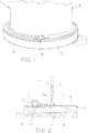
- FIGS. 1 and 2 show an embodiment of a tank 1 having sides 2 and bottom base plate 7 wherein a chime seal 3 is utilized to encapsulate or house a perforated corrosion inhibitor pipe 4 that is in communication with tank soil side bottom 5 and generally the substrate 6.
- the chime seal has one leg that resides upon a hard surface portion of substrate 6, for example, concrete or asphalt, that extends outwardly of the periphery of the perforated pipe 4, and chime seal 3 optionally has another leg that resides upon the top surface of the outward extending tank base plate edge 7A. Both legs of the chime are sealed.
- the delivery system relates to various one or more corrosion inhibitors being supplied in a permeable casing, not shown, through refill port 8 that is connected to an end of perforated pipe 4, which has perforations 9 positioned such that the corrosion inhibitor is allowed to communicate with tank soil side bottom 5.
- Chime openings 10 and the perforated pipe end openings are desirably located adjacent to one another.
- the corrosion inhibitor can flow underneath tank baseplate edge or annulus 7A and baseplate 7 and flow toward the center of the tank soil side bottom. That is, chime seal 3 acts to confine the corrosion inhibitor to the void space 11 under the tank soil side bottom plate 5 whereupon it contacts and/or coats the tank bottom plate 5 and forms a protective corrosion inhibitor surface thereon.
- the bottom of the storage tank performs a breathing action due to slight movement of the tank bottom with respect to filling and entering operations, draining operations, temperature, and the like. Due to these inherent breathing aspects, the corrosion inhibitors are drawn or pulled into the small open or void areas 11 beneath tank bottom plate 5. As with the other embodiments, the corrosion inhibitors can even be soluble inhibitors, generally not preferred, volatile corrosion inhibitors, which are preferred, or a mixture thereof, which is also preferred.
- An advantage of the present invention is that it is essentially or preferably free of any perforated pipe or similar embodiments that extend to substrate area 6 located beneath tank 1 generally within side walls 2. Thus, there is no need to drill or dig into substrate area 6 to install perforated pipes therein.
- An advantage of the same is that expensive construction and/or installation costs are eliminated.
- Other advantages are similar to those set forth above and the fact that the corrosion inhibitors can be replenished as needed, automatically, or by any other system as described herein above.
- Another advantage is that the present invention is ideally suited for storage tanks wherein the void space or volume between the tank bottom and substrate are small.
- the inhibitors can be applied in solid form or in liquid form.
- soluble corrosion inhibitors include, but are not limited to, mixtures of ZnSO 4 and NaH 2 PO 4 , organic nitrites, imidazoles and organic aminophosphites.
- Suitable solvents for such soluble corrosion inhibitors include, but are not limited to, aqueous solutions including those of sodium, potassium, and calcium compounds, or mixtures of two or more thereof. The strength and/or concentration of such aqueous solvents will depend, in part, upon the amount of soluble corrosion inhibitor to be dissolved therein. Accordingly, the present invention is not limited to any one set of strengths and/or concentrations of solvents for the soluble corrosion inhibitors disclosed herein.
- Suitable sodium and calcium compounds for use in forming the above-mentioned aqueous solvents include, but are not limited to, Na 2 MoO 4 , Na 3 PO 4 , NaH 2 PO 4 , NaNO 2 , Na 2 SiO 3 , calcium phosphonate, or suitable mixtures of two or more thereof.
- corresponding potassium compounds can be used in place of the above-mentioned sodium compounds.
- the one or more soluble corrosion inhibitors of the present invention are powders in granular form. However, the present invention is not limited to only the above-mentioned forms.
- VCI compounds for use in connection with the present invention are known in the art and, as such, any suitable volatile or vapor phase corrosion inhibitors can be used in the rust-resistant perforated pipes of the present invention.
- Suitable VCIs for use in the present invention are disclosed in U.S. Pat. Nos. 4,290,912 ; 5,320,778 ; and 5,855,975 .
- Examples of VCIs set forth in U.S. Pat. No. 4,290,912 include inorganic nitrite salts including metal nitrites, preferably Group I and II metal nitrites such as potassium nitrite, sodium nitrite, barium nitrite, and calcium nitrite.
- VCIs set forth in U.S. Pat. No. 5,320,778 include anhydrous sodium molybdate [Na 2 MoO 4 ], anhydrous ammonium dimolybdate [(NH 4 ) 2 MoO 4 ], or an anhydrous amine-molybdate.
- the preferred amine molybdates of this component of the composites of the present invention are amine-molybdates comprising dicyclohexylamine, 2-ethylhexylamine, and cyclohexylamine.
- Another group of VCIs comprise amine benzoates, amine nitrates, and benzotriazole.
- VCIs comprise cyclohexylamine benzoate, ethylamine benzoate, dicyclohexylamine nitrate and benzotriazole.
- VCIs set forth in U.S. Pat. No. 5,855,975 include sodium nitrite and benzotriazole.
- Useful volatile or vapor phase corrosion inhibitors also include but are not limited to, benzotriazole, tolytriazole and salts thereof, mixtures of benzoates of amine salts with benzotriazole, nitrates of amine salts, and C 13 H 26 O 2 N.
- FIG. 3 relates to an embodiment of the present invention somewhat similar to the embodiments of FIGS. 1 and 2 but additionally contains a ring wall.
- tank 1 contains a sidewall 2 that is located on tank base plate 7 that extends the entire diameter or width of the tank and has a slight exterior circumferential annulus or edge that extends readily outward of the tank side wall.
- Chime seal 3 is desirably located in the vicinity of the outer end of bottom exterior edge 7A and the top of ring wall 20 as shown in FIG. 3 .
- the chime seal contains refill ports that allow perforated pipe 4 to be inserted therein and subsequently various one or more SCI and/or one or more VCI compounds.
- ring wall 20 instead of being located on a hard substrate surface such as asphalt or concrete, is located below tank side wall 2 so that it can support the same.
- Ring wall 20 is made of a hard material, usually concrete or the like, and extends downward into the ground beneath tank 1 thus forming a cylinder.
- Substrate 6 located within ring wall 20, as noted above, can either be hard, for example concrete or asphalt, or porous such as sand, small stones such as pebbles, actual soil such as clay, loam or a sandy soil, and the like.
- the substrate located radially inward of ring wall 20 is sand wherein the same was placed there prior to the installation of the tank.
- liner 22 is utilized under porous substrate 6.
- the liner desirably is a polymer or other non-corrosive material that is generally impermeable with regard to the SCI and/or VCI compounds. Suitable plastics include PVC, polyolefins such as polyethylene, and polyurethanes. Alternatively, liner 22 can be located under the entire tank base plate or any portion thereof.
- interior substrate 6 can be a hard material that extends across the entire area within ring wall 20, or it can extend partially into the inner tank area, as say a few or several inches, or to any extent therebetween. Conversely, the remaining non hard area can be a porous area.
- FIG. 3 Another embodiment of FIG. 3 is that the substrate located radially outward the ring wall 20 can be hard.
Landscapes
- Engineering & Computer Science (AREA)
- Chemical & Material Sciences (AREA)
- Mechanical Engineering (AREA)
- Architecture (AREA)
- Organic Chemistry (AREA)
- Metallurgy (AREA)
- Materials Engineering (AREA)
- Civil Engineering (AREA)
- Structural Engineering (AREA)
- General Engineering & Computer Science (AREA)
- Paleontology (AREA)
- Mining & Mineral Resources (AREA)
- General Life Sciences & Earth Sciences (AREA)
- Life Sciences & Earth Sciences (AREA)
- Preventing Corrosion Or Incrustation Of Metals (AREA)
- Filling Or Discharging Of Gas Storage Vessels (AREA)
- Underground Structures, Protecting, Testing And Restoring Foundations (AREA)
- Working Measures On Existing Buildindgs (AREA)
- Physics & Mathematics (AREA)
- Electromagnetism (AREA)
Description
- The present invention relates to a storage tank having a soil side bottom located on a substrate by application of an inhibitor ring delivery system about the periphery of the tank and wherein corrosion inhibitors can be readily admitted via the ring delivery system into the spaces between the substrate and the tank bottom (soil side) to protect the same against corrosion. The invention relates further to a method for retrofitting and protecting a storage tank.
- In aboveground storage tanks, corrosion of soil side bottoms and double bottoms is unpredictable and can reduce the thickness of the tank bottom up to about 5mm/year. There are multiple tank bottom and foundation designs that address some of the corrosion problems. A typical corrosion protection method, i.e., cathodic protection system, in most cases is not effective due to inherent dry soil conditions at least during some part of a year. The use of soluble corrosion inhibitors, as with cathodic systems, is only viable in fully saturated sand or soil and it is generally difficult to obtain such saturated conditions. Protective coatings cannot be applied to existing or new tank soil side bottoms.
- In summary, corrosion of aboveground storage tanks either with a single soil side bottom or a double bottom is a major worldwide problem.
DE102004002217A1 discloses a storage tank. Such tanks face unpredictable application and environmental conditions that often cause the bottoms to leak. Polymer protection layers can be damaged or become water permeable over time and result in leaks of the stored product, which can lead to severe environmental impact requiring extensive cleanup activities along with environmental fines and other costs. Moreover, dangerous operating conditions occur when the leaking product is volatile or flammable. Another disadvantage is that repair of tank bottoms generally requires down time. - The problem is solved by a storage tank according to claim 1 and by a method according to claim 8. A method for retrofitting and protecting a storage tank soil side bottom, comprising the steps of obtaining a storage tank having side walls and a bottom base plate; said bottom base plate having an edge extending outward of said tank side walls, said tank located on a substrate; installing a perforated pipe system around at least a portion of said tank bottom plate edge so that perforations of said pipe system are in communication with said substrate under said tank bottom base plate; installing a chime seal system about at least a portion of said tank bottom base plate edge, said chime seal forming an enclosure for said perforated pipe system, said tank base plate having one or more openings to provide access for said perforated pipe system to said substrate under the tank bottom base plate, said chime seal having one leg contacting said tank base plate; and introducing a corrosion inhibitor into said perforated pipe system so that said corrosion inhibitor is dispersed into said substrate under the said tank bottom base plate. A storage tank having a soil side bottom, the storage tank having side walls and a bottom base plate; said base plate extending outward of said side walls; said tank located on a substrate; a chime seal located around at least an external portion of the perimeter of said tank bottom, base plate, said chime seal having one or more openings therein that communicate with said substrate, said chime seal having a leg contacting said tank base plate; a perforated pipe located within said chime seal having at least one perforation and wherein said perforation is in communication with said tank base plate and said substrate; and a corrosion inhibitor adapted to be fed into said perforated pipe so that said corrosion inhibitor is dispersed into said substrate.
-
-
FIG. 1 is a perspective view of the present invention. -
FIG. 2 is a cross-section side elevation view ofFIG. 1 . -
FIG. 3 is a cross-section side elevation view of an embodiment containing a ring wall and a liner. - Storage tanks 1 have
side walls 2 andbottom base plates 7 that inherently are contained or located upon asubstrate 6. The bottom base plate extends across the entire bottom of the tank and generally extends outwardly thereof to form an external bottom base plate edge, flange, or annulus 7A. Substrates typically encompass hard surface materials such as concrete and asphalt, etc., either alone or in conjunction with porous materials such as soil, e.g. clay, loam, sandy soils, sand, fine or small-sized stones, pebbles, etc. The external side of the tank bottom plate surface that is situated on or contacts the substrate typically is referred to as the soil side bottom 5. Hard materials or substrates can be located under the entire tank bottom or at least desirably in the vicinity under the tank sides to support the weight thereof. Various porous substrates sometimes referred to as being partially hard can also extend under the entire tank bottom base plate, but it is often desirable that they extend only in the internal tank area as within the tank sides. In this situation, the area beneath the tank side walls will either contain a hard substrate or a ring wall as further set forth herein below. Of course, combinations of hard substrates and porous substrates can be utilized such as concentric ring portions, and the like. Original ornatural substrate 15 is typically firm earth such as soil or clay and optionally can be located beneath tank 1 withintank side wall 2 in lieu ofporous substrate 6. - The tank soil side bottoms are subject to corrosion during the course of time. Corrosion protection of the present system is also achieved through the utilization of various one or more corrosion inhibitors such as water soluble corrosion inhibitors (SCI) and preferably volatile corrosion inhibitors (VCI) to protect tank soil side bottoms 5.
- An inhibitor ring delivery system is used such as a
chime seal 3 that extends at least around an external (perimeter) portion of the tankbottom base plate 7 circumference, desirably around a majority of the tank bottom plate circumference, and preferably around the entire tank bottom plate circumference thereof. The chime seal can be plastic, mastic, asphalt, bitumen or elastomer and exists generally on the external edge of the tank bottom base plate or, preferably can be an integral part thereof.Chime seal 3 has at least one refill port 8 that is an opening at the end thereof as shown inFIG. 1 , whereby a perforated pipe 9 can be inserted therein. It also serves as an opening into which SCI or VCIs can be added. As explained in greater detail herein below, perforated pipe 9, or in other words the inhibitor ring delivery system, can extend inside thetank chime seal 3 about a portion, desirably around the majority of the tank bottom plate edge or periphery, or preferably extend about the entire periphery thereof. The purpose of the chime seal is to keep moisture, water, etc. out ofperforated pipe 4 and keep the corrosion inhibitor in, i.e. trapped under the tank bottom. - Perforated pipe 9 can be made out of any material that is not affected by the corrosion inhibitors and is not degraded by water. Flexible plastics such as thermoplastics and rubbers are thus preferred. The perforated pipe diameter, as well as the sizes, positions and number of the one or more perforations (holes) can vary. For example, using a 1-inch diameter pipe, one or two rows of perforations are typically used. If two rows are used, the rows are typically positioned at 180° of arc. The perforations are typically round, in the range of 0.25-inch diameter, but can also be oblong or slotted, and spaced in the range of 2 inches apart.
- It is important that perforated pipe holes 9 are be- in communication with the substrate so that corrosion inhibitors admitted or injected therefrom can permeate the substrate and contact the soil side of the tank bottom plate to protect the same from corrosion. The term "communication" is defined here are meaning there are pathways, channels, openings, and the like for the corrosive inhibitor to be introduced into the area formed between the substrate, the tank soil side bottom and the chime seal.
- Additional advantages of the corrosion inhibitor delivery systems for tank soil side bottoms are that it is very convenient to supply various corrosion inhibitors to the substrate area, that one or more different corrosion inhibitors can be utilized, that the corrosion inhibitors can be applied at any desired time and duration, and that the corrosion inhibitors can be replenished in the inhibitor ring delivery system without disruption to tank operations. Inhibitor replenishment can be performed when needed and can be controlled manually, automatically with respect to certain times and duration thereof, or automatically upon receiving feedback as from sensors, etc.
- Reference is now made to a specific embodiment as set forth in
FIGS. 1-3 by way of example. -
FIGS. 1 and 2 show an embodiment of a tank 1 havingsides 2 andbottom base plate 7 wherein achime seal 3 is utilized to encapsulate or house a perforatedcorrosion inhibitor pipe 4 that is in communication with tank soil side bottom 5 and generally thesubstrate 6. The chime seal has one leg that resides upon a hard surface portion ofsubstrate 6, for example, concrete or asphalt, that extends outwardly of the periphery of theperforated pipe 4, andchime seal 3 optionally has another leg that resides upon the top surface of the outward extending tank base plate edge 7A. Both legs of the chime are sealed. The delivery system relates to various one or more corrosion inhibitors being supplied in a permeable casing, not shown, through refill port 8 that is connected to an end ofperforated pipe 4, which has perforations 9 positioned such that the corrosion inhibitor is allowed to communicate with tank soil side bottom 5.Chime openings 10 and the perforated pipe end openings are desirably located adjacent to one another. Upon delivery of one or more corrosion inhibitors through ports 8 intoperforated pipe 4, the same will flow throughpipe 4 and flow out of perforations 9. Due to the fact that both the top surface ofsubstrate 6 and the tank soil side bottom surface 5 are never even, but contain undulations and openings therein, the corrosion inhibitor can flow underneath tank baseplate edge or annulus 7A andbaseplate 7 and flow toward the center of the tank soil side bottom. That is,chime seal 3 acts to confine the corrosion inhibitor to the void space 11 under the tank soil side bottom plate 5 whereupon it contacts and/or coats the tank bottom plate 5 and forms a protective corrosion inhibitor surface thereon. - As known to those skilled in the art, the bottom of the storage tank performs a breathing action due to slight movement of the tank bottom with respect to filling and entering operations, draining operations, temperature, and the like. Due to these inherent breathing aspects, the corrosion inhibitors are drawn or pulled into the small open or void areas 11 beneath tank bottom plate 5. As with the other embodiments, the corrosion inhibitors can even be soluble inhibitors, generally not preferred, volatile corrosion inhibitors, which are preferred, or a mixture thereof, which is also preferred.
- An advantage of the present invention is that it is essentially or preferably free of any perforated pipe or similar embodiments that extend to
substrate area 6 located beneath tank 1 generally withinside walls 2. Thus, there is no need to drill or dig intosubstrate area 6 to install perforated pipes therein. An advantage of the same is that expensive construction and/or installation costs are eliminated. Other advantages are similar to those set forth above and the fact that the corrosion inhibitors can be replenished as needed, automatically, or by any other system as described herein above. Another advantage is that the present invention is ideally suited for storage tanks wherein the void space or volume between the tank bottom and substrate are small. - The inhibitors can be applied in solid form or in liquid form.
- With respect to soluble corrosion inhibitors, they include, but are not limited to, mixtures of ZnSO4 and NaH2PO4, organic nitrites, imidazoles and organic aminophosphites. Suitable solvents for such soluble corrosion inhibitors include, but are not limited to, aqueous solutions including those of sodium, potassium, and calcium compounds, or mixtures of two or more thereof. The strength and/or concentration of such aqueous solvents will depend, in part, upon the amount of soluble corrosion inhibitor to be dissolved therein. Accordingly, the present invention is not limited to any one set of strengths and/or concentrations of solvents for the soluble corrosion inhibitors disclosed herein. Suitable sodium and calcium compounds for use in forming the above-mentioned aqueous solvents include, but are not limited to, Na2MoO4, Na3PO4, NaH2PO4, NaNO2, Na2SiO3, calcium phosphonate, or suitable mixtures of two or more thereof. In another instance, corresponding potassium compounds can be used in place of the above-mentioned sodium compounds. In another example, the one or more soluble corrosion inhibitors of the present invention are powders in granular form. However, the present invention is not limited to only the above-mentioned forms.
- In connection with the present invention, suitable VCI compounds for use in connection with the present invention are known in the art and, as such, any suitable volatile or vapor phase corrosion inhibitors can be used in the rust-resistant perforated pipes of the present invention. Suitable VCIs for use in the present invention are disclosed in
U.S. Pat. Nos. 4,290,912 ;5,320,778 ; and5,855,975 . Examples of VCIs set forth inU.S. Pat. No. 4,290,912 include inorganic nitrite salts including metal nitrites, preferably Group I and II metal nitrites such as potassium nitrite, sodium nitrite, barium nitrite, and calcium nitrite. Examples of VCIs set forth inU.S. Pat. No. 5,320,778 include anhydrous sodium molybdate [Na2MoO4], anhydrous ammonium dimolybdate [(NH4)2MoO4], or an anhydrous amine-molybdate. The preferred amine molybdates of this component of the composites of the present invention are amine-molybdates comprising dicyclohexylamine, 2-ethylhexylamine, and cyclohexylamine. Another group of VCIs comprise amine benzoates, amine nitrates, and benzotriazole. Other VCIs comprise cyclohexylamine benzoate, ethylamine benzoate, dicyclohexylamine nitrate and benzotriazole. Examples of VCIs set forth inU.S. Pat. No. 5,855,975 include sodium nitrite and benzotriazole. Useful volatile or vapor phase corrosion inhibitors also include but are not limited to, benzotriazole, tolytriazole and salts thereof, mixtures of benzoates of amine salts with benzotriazole, nitrates of amine salts, and C13H26O2N. -
FIG. 3 relates to an embodiment of the present invention somewhat similar to the embodiments ofFIGS. 1 and 2 but additionally contains a ring wall. As shown inFIG. 3 , tank 1 contains asidewall 2 that is located ontank base plate 7 that extends the entire diameter or width of the tank and has a slight exterior circumferential annulus or edge that extends readily outward of the tank side wall.Chime seal 3 is desirably located in the vicinity of the outer end of bottom exterior edge 7A and the top of ring wall 20 as shown inFIG. 3 . Although not shown, the chime seal contains refill ports that allowperforated pipe 4 to be inserted therein and subsequently various one or more SCI and/or one or more VCI compounds. Such compounds, as noted above, will flow throughperforated pipe 4 enclosed withinchime seal 3 and exit desirably at the bottom portion thereof through perforations 9 so that they can enter void spaces 11 inherently located under tank soil side bottom 5 and flow radially inwardly toward the center of the tank. In this embodiment, ring wall 20, instead of being located on a hard substrate surface such as asphalt or concrete, is located belowtank side wall 2 so that it can support the same. Ring wall 20, of course, is made of a hard material, usually concrete or the like, and extends downward into the ground beneath tank 1 thus forming a cylinder.Substrate 6 located within ring wall 20, as noted above, can either be hard, for example concrete or asphalt, or porous such as sand, small stones such as pebbles, actual soil such as clay, loam or a sandy soil, and the like. In the embodiment ofFIG. 3 , the substrate located radially inward of ring wall 20 is sand wherein the same was placed there prior to the installation of the tank. In order to prevent the SCI and/or VCI from penetratingsand substrate 6 and permeating down into the ground or soil underneath the ring wall and laterally (radially outwardly) exiting therefrom,liner 22 is utilized underporous substrate 6. The liner desirably is a polymer or other non-corrosive material that is generally impermeable with regard to the SCI and/or VCI compounds. Suitable plastics include PVC, polyolefins such as polyethylene, and polyurethanes. Alternatively,liner 22 can be located under the entire tank base plate or any portion thereof. - While in the embodiment of
FIG. 3 , a porous substrate is utilized within ring wall cylinder, other embodiments exist. For example,interior substrate 6 can be a hard material that extends across the entire area within ring wall 20, or it can extend partially into the inner tank area, as say a few or several inches, or to any extent therebetween. Conversely, the remaining non hard area can be a porous area. Another embodiment ofFIG. 3 is that the substrate located radially outward the ring wall 20 can be hard.
Claims (14)
- A storage tank (1) having a soil side bottom, the storage tank (1) having side walls (2) and a bottom base plate (7); said bottom base plate is extending outward of said side walls (2); said tank (1) is located on a substrate (6); a perforated pipe (4) having at least one perforation (5) and wherein said perforation (5) is in communication with said tank bottom base plate (7) and said substrate (6), characterised in that a chime seal (3) is located around at least an external portion of the perimeter of said tank bottom base plate (7), said chime seal (3) having one or more openings (10) therein that communicate with said substrate (6), said chime seal (3) having a leg contacting said tank bottom base plate (7); the perforated pipe (4) is located within said chime seal (3); and a corrosion inhibitor is adapted to be fed into said perforated pipe (4) so that said corrosion inhibitor is dispersed into said substrate (6).
- A storage tank (1) according to claim 1, wherein said tank bottom base plate (7) is a new tank bottom or an old tank bottom base plate (7); wherein said corrosion inhibitor is a soluble corrosion inhibitor, a volatile corrosion inhibitor, or both, wherein said chime seal (3) extends entirely around said perimeter of said tank base plate (7), wherein said perforated pipe (4) extends entirely around the perimeter of said tank base plate (7),
wherein said chime seal (3) contains a plurality of openings (10) therein, wherein said perforated pipe (4) contains a plurality of perforations (9) therein, wherein said chime seal openings (10) and said perforated pipe perforations (9) are located adjacent to each other, and including another chime seal leg that contacts said substrate (6). - A storage tank (1) according to claim 2, wherein at least a portion of said substrate (6) is porous, and including a liner (22), said liner (22) located under said porous substrate portion.
- A storage tank (1) according to claim 1, wherein a portion of said substrate (6) is a hard substrate located beneath said tank side wall (2), and wherein said substrate (6)located radially inward of said hard substrate is porous, and including a liner (22), said liner (22) located below said porous substrate (6).
- A storage tank according to claim 1, wherein said chime seal (3) extends entirely around said perimeter of said tank;
wherein said perforated pipe (4) extends around the entire perimeter of said tank bottom (5);
wherein said chime has openings (10) and wherein said pipe perforations (9) are located adjacent to said chime openings (10). - A storage tank according to claim 5, wherein said corrosion inhibitor is a soluble inhibitor, or wherein said corrosion inhibitor is a volatile corrosion inhibitor, or both, wherein said substrate (6) is porous, and including said liner (22).
- A storage tank according to claim 5, wherein said storage tank bottom (5) is a new storage tank bottom, or wherein said storage tank bottom (5) is an existing tank bottom.
- A method for retrofitting and protecting a soil side storage tank bottom (5), comprising the steps of:obtaining a storage tank having side walls (2) and a bottom base plate (7); said bottom base plate (7) having an edge (7A) extending outward of said tank side walls (2), said tank located on a substrate (6);installing a perforated pipe system (4) around at least a portion of said tank bottom plate edge (7A) so that perforations (9) of said pipe system (4) are in communication with said substrate (6) under said tank bottom base plate (7);installing a chime seal system (3) about at least a portion of said tank bottom base plate edge (7A), said chime seal (3) forming an enclosure for said perforated pipe system and providing access for said perforated pipe system to said substrate (6)under the tank bottom base plate, said chime seal (3) having one leg contacting said tank base plate (7); andintroducing a corrosion inhibitor into said perforated pipe system so that said corrosion inhibitor is dispersed into said substrate (6) under the said tank bottom base plate (7).
- The method of claim 8, wherein said chime seal (3) has openings (10) therein and extends entirely around said tank bottom plate edge (7A), and wherein said perforated pipe (4) extends entirely around said tank bottom plate edge (7A).
- The method of claim 9, wherein said chime openings (10) and said pipe perforations (9) are located adjacent to each other, wherein said corrosion inhibitor is a soluble inhibitor, or wherein said corrosion inhibitor is a volatile corrosion inhibitor, or both; and
wherein said storage tank bottom (5) is a new storage tank bottom, or wherein said storage tank bottom (5) is an existing tank bottom. - The method of claim 8, wherein, wherein said chime seal (3) has one or more openings (10) therein that communicate with said substrate (6).
- The method of claim 11, wherein said tank bottom base plate (7) is a new tank bottom or an old tank bottom base plate, and wherein said corrosion inhibitor is a soluble corrosion inhibitor, a volatile corrosion inhibitor, or both.
- The method of claim 11, wherein said chime seal (3) extends entirely around said perimeter of said tank bottom base plate (7), wherein said perforated pipe (4) extends entirely around the perimeter of said tank bottom base plate (7), wherein said chime seal (3) contains a plurality of openings (10) therein, wherein said chime openings (10) and said perforated pipe perforations (9) are located adjacent to each other, including another chime seal leg contacting said substrate (6), and wherein said corrosion inhibitor is a volatile corrosion inhibitor.
- The method of claim 13, wherein a portion of said substrate (6) is a hard substrate located beneath said tank side wall (2) and wherein the remaining portion of said substrate (6) is porous, and including a liner (22), said liner (22) located under said porous substrate (6).
Applications Claiming Priority (3)
| Application Number | Priority Date | Filing Date | Title |
|---|---|---|---|
| US201361892785P | 2013-10-18 | 2013-10-18 | |
| US14/514,505 US9303380B2 (en) | 2013-10-18 | 2014-10-15 | Systems for corrosion protection of storage tank soil side bottoms |
| PCT/US2014/060815 WO2015057914A1 (en) | 2013-10-18 | 2014-10-16 | Systems for corrosion protection of storage tank soil side bottoms |
Publications (3)
| Publication Number | Publication Date |
|---|---|
| EP3057676A1 EP3057676A1 (en) | 2016-08-24 |
| EP3057676A4 EP3057676A4 (en) | 2017-05-03 |
| EP3057676B1 true EP3057676B1 (en) | 2018-01-31 |
Family
ID=52825264
Family Applications (1)
| Application Number | Title | Priority Date | Filing Date |
|---|---|---|---|
| EP14853299.7A Active EP3057676B1 (en) | 2013-10-18 | 2014-10-16 | Storage tank, method |
Country Status (12)
| Country | Link |
|---|---|
| US (1) | US9303380B2 (en) |
| EP (1) | EP3057676B1 (en) |
| CN (1) | CN105705214B (en) |
| AU (1) | AU2014337267C1 (en) |
| BR (1) | BR112016008681A8 (en) |
| CA (1) | CA2927558C (en) |
| GE (1) | GEP20186846B (en) |
| MX (1) | MX368422B (en) |
| MY (1) | MY174669A (en) |
| SA (1) | SA516370904B1 (en) |
| SG (1) | SG11201602728VA (en) |
| WO (1) | WO2015057914A1 (en) |
Families Citing this family (8)
| Publication number | Priority date | Publication date | Assignee | Title |
|---|---|---|---|---|
| US8734052B2 (en) * | 2008-10-20 | 2014-05-27 | Falcon Technologies And Services, Inc. | Tank base |
| WO2018057617A1 (en) * | 2016-09-21 | 2018-03-29 | Cortec Corporation | Chemical dispensing system to mitigate soil-side corrosion |
| CN107352181B (en) * | 2017-05-02 | 2023-06-02 | 莱州市新力复合材料有限公司 | Large-scale compound storage tank mounting structure |
| CN110172702B (en) * | 2019-05-17 | 2021-11-02 | 中国石油天然气集团有限公司 | Anti-corrosion method for outer surface of bottom plate of underground vertical storage tank |
| TWI708918B (en) * | 2020-04-01 | 2020-11-01 | 特極股份有限公司 | Helical pile and bracket module comprising the same |
| CN111794549B (en) * | 2020-07-07 | 2021-11-09 | 中国化学工程第十四建设有限公司 | Construction method for lowering height and changing bottom of vertical storage tank |
| US12447515B2 (en) | 2021-06-15 | 2025-10-21 | Saudi Arabian Oil Company | System and method for deploying volatile corrosion inhibitor to protect against soil side corrosion at the bottom of a storage tank |
| US12398472B2 (en) | 2021-12-16 | 2025-08-26 | Saudi Arabian Oil Company | Intelligent system using an IoT architectural framework to control deployment of volatile corrosion inhibitors (VCIs) for soil-side corrosion mitigation of aboveground storage tanks |
Family Cites Families (16)
| Publication number | Priority date | Publication date | Assignee | Title |
|---|---|---|---|---|
| US4290912A (en) | 1980-02-21 | 1981-09-22 | Northern Instruments Corporation | Volatile corrosion inhibiting article |
| CA1207970A (en) | 1983-11-14 | 1986-07-22 | Columbia Reservoir Systems (1977) Ltd. | Demountable portable reservoir structure |
| US5320778A (en) | 1988-08-23 | 1994-06-14 | Cortec Corporation | Vapor phase corrosion inhibitor-desiccant material |
| US5172584A (en) * | 1989-08-02 | 1992-12-22 | Coretank, Inc. | Secondary containment and leak detection apparatus |
| US5096087A (en) * | 1989-08-02 | 1992-03-17 | Coretank, Inc. | Double containment and leak detection apparatus |
| ES2077550T3 (en) | 1993-11-09 | 2000-05-16 | Cortec Corp | ANTICORROSION PLASTIC FILM WITH RECYCLED RESIN. |
| US6171029B1 (en) | 1997-05-12 | 2001-01-09 | Mcgill Milton D. | Method and apparatus for retrofitting underground storage tanks with a containment sump |
| US6099735A (en) | 1998-06-04 | 2000-08-08 | Kelada; Maher I. | Counter top reverse osmosis water purification system |
| DE102004002217B4 (en) * | 2004-01-15 | 2006-02-09 | S. Müller Patent Entwicklungs und Verpachtungs GmbH & Co. KG | Device for long-term leak monitoring of double-walled vessel systems, in particular flat tank structures with double tank bottom |
| DE102005053911A1 (en) * | 2005-08-08 | 2007-02-15 | S. Müller Patent Entwicklungs und Verpachtungs GmbH & Co. KG | Retro-fitting tank with leakage protection measures, raises tank, makes base liquid tight and adds tank supports, interceptor and instrumentation |
| US8297006B2 (en) | 2008-05-19 | 2012-10-30 | Watson Timothy L | Foundational cistern |
| US7874764B2 (en) * | 2008-06-27 | 2011-01-25 | Peter Van Fossen | Secondary containment system for an above-ground petroleum storage tank |
| US8475078B2 (en) * | 2008-11-22 | 2013-07-02 | Thomas Alan Denning | Containment device, method and system |
| US20140197563A1 (en) | 2010-12-15 | 2014-07-17 | Robert Niven | Carbon dioxide sequestration in concrete articles |
| CN102658932B (en) * | 2012-05-15 | 2013-12-04 | 天津利达昌基科技发展有限公司 | Flexible grease fiber anticorrosion sealing system and application thereof in storage tank margin plate |
| CN102785874B (en) * | 2012-08-16 | 2013-12-25 | 浙江省特种设备检验研究院 | Vertical storage tank leakage monitoring system with dual-layer tank bottom plate structure |
-
2014
- 2014-10-15 US US14/514,505 patent/US9303380B2/en active Active
- 2014-10-16 MY MYPI2016000669A patent/MY174669A/en unknown
- 2014-10-16 GE GEAP201414148A patent/GEP20186846B/en unknown
- 2014-10-16 AU AU2014337267A patent/AU2014337267C1/en not_active Ceased
- 2014-10-16 EP EP14853299.7A patent/EP3057676B1/en active Active
- 2014-10-16 CA CA2927558A patent/CA2927558C/en active Active
- 2014-10-16 BR BR112016008681A patent/BR112016008681A8/en not_active Application Discontinuation
- 2014-10-16 SG SG11201602728VA patent/SG11201602728VA/en unknown
- 2014-10-16 WO PCT/US2014/060815 patent/WO2015057914A1/en not_active Ceased
- 2014-10-16 MX MX2016005012A patent/MX368422B/en active IP Right Grant
- 2014-10-16 CN CN201480056844.6A patent/CN105705214B/en not_active Expired - Fee Related
-
2016
- 2016-04-10 SA SA516370904A patent/SA516370904B1/en unknown
Non-Patent Citations (1)
| Title |
|---|
| None * |
Also Published As
| Publication number | Publication date |
|---|---|
| CN105705214A (en) | 2016-06-22 |
| SG11201602728VA (en) | 2016-05-30 |
| GEP20186846B (en) | 2018-04-25 |
| AU2014337267A1 (en) | 2016-04-21 |
| CA2927558A1 (en) | 2015-04-23 |
| MX2016005012A (en) | 2017-02-28 |
| AU2014337267B2 (en) | 2016-10-20 |
| MX368422B (en) | 2019-10-02 |
| BR112016008681A8 (en) | 2020-03-17 |
| EP3057676A1 (en) | 2016-08-24 |
| CA2927558C (en) | 2018-01-09 |
| EP3057676A4 (en) | 2017-05-03 |
| CN105705214B (en) | 2017-11-14 |
| AU2014337267C1 (en) | 2017-05-04 |
| WO2015057914A1 (en) | 2015-04-23 |
| US9303380B2 (en) | 2016-04-05 |
| MY174669A (en) | 2020-05-06 |
| SA516370904B1 (en) | 2017-10-11 |
| US20150108148A1 (en) | 2015-04-23 |
Similar Documents
| Publication | Publication Date | Title |
|---|---|---|
| US9303380B2 (en) | Systems for corrosion protection of storage tank soil side bottoms | |
| EP3137395B1 (en) | A storage tank bottom corrosion protection system | |
| FI69503C (en) | YTBELAGD BERGSBEHAOLLARE ELLER TUNNEL | |
| US11427982B2 (en) | Tank base | |
| US9248960B2 (en) | Dual-tank liquid storage system | |
| US20150041409A1 (en) | Reactive Treatment Cell and Systems For Environmental Remediation | |
| US20110305516A1 (en) | Hydraulically impervious earthen pond | |
| US20130272793A1 (en) | Containment device, method and system | |
| CN106564976A (en) | Deep filtering cylinder for garbage leachate | |
| US2955018A (en) | Corrosion inhibition | |
| Vogel | Air emission control at hazardous waste management facilities | |
| JPH08134944A (en) | Waterproofing method for underground structures | |
| US20060280561A1 (en) | Method of creating and sustaining earthen hard pan formations | |
| KR100719749B1 (en) | Cylindrical injection bag for ground water | |
| US20100012319A1 (en) | Plug and method for establishing such plug inside a pipe | |
| KR101940022B1 (en) | Compartmentalized waterproofing system for underground structure | |
| RU2095300C1 (en) | Carbon steel reservoir for storing liquid nitrogen fertilizers | |
| BR102023015536A2 (en) | CONSTRUCTION DISPOSITION IN ROTOMOLDED DRAINAGE CHAMBER MADE OF POLYETHYLENE FOR MANAGEMENT AND INFILTRATION OF TREATED EFFLUENT AND RAINWATER INTO THE SOIL | |
| FI82289B (en) | BERGSBEHAOLLARE ELLER TUNNEL. | |
| NO20082974L (en) | Method for stopping concrete layers, a device and a pulp for carrying this process feed | |
| JPH0617423A (en) | Pile | |
| CS221479B1 (en) | Foil ground tank | |
| JP2004036096A (en) | Soil pollution prevention structure | |
| JPH08199563A (en) | Foundation pile |
Legal Events
| Date | Code | Title | Description |
|---|---|---|---|
| PUAI | Public reference made under article 153(3) epc to a published international application that has entered the european phase |
Free format text: ORIGINAL CODE: 0009012 |
|
| 17P | Request for examination filed |
Effective date: 20160427 |
|
| AK | Designated contracting states |
Kind code of ref document: A1 Designated state(s): AL AT BE BG CH CY CZ DE DK EE ES FI FR GB GR HR HU IE IS IT LI LT LU LV MC MK MT NL NO PL PT RO RS SE SI SK SM TR |
|
| AX | Request for extension of the european patent |
Extension state: BA ME |
|
| DAX | Request for extension of the european patent (deleted) | ||
| A4 | Supplementary search report drawn up and despatched |
Effective date: 20170330 |
|
| RIC1 | Information provided on ipc code assigned before grant |
Ipc: B01D 61/10 20060101ALI20170325BHEP Ipc: E04H 7/06 20060101ALI20170325BHEP Ipc: B65D 90/24 20060101ALI20170325BHEP Ipc: B01D 61/08 20060101ALI20170325BHEP Ipc: B01D 35/027 20060101AFI20170325BHEP Ipc: B23P 11/00 20060101ALI20170325BHEP |
|
| GRAP | Despatch of communication of intention to grant a patent |
Free format text: ORIGINAL CODE: EPIDOSNIGR1 |
|
| STAA | Information on the status of an ep patent application or granted ep patent |
Free format text: STATUS: GRANT OF PATENT IS INTENDED |
|
| INTG | Intention to grant announced |
Effective date: 20170904 |
|
| GRAS | Grant fee paid |
Free format text: ORIGINAL CODE: EPIDOSNIGR3 |
|
| GRAA | (expected) grant |
Free format text: ORIGINAL CODE: 0009210 |
|
| STAA | Information on the status of an ep patent application or granted ep patent |
Free format text: STATUS: THE PATENT HAS BEEN GRANTED |
|
| RIN1 | Information on inventor provided before grant (corrected) |
Inventor name: RAMDAS, GAUTAM Inventor name: POSNER, MONIQUE HUMBERT Inventor name: LYUBLINSKI, EFIM YA Inventor name: NATALE, TERRY ALAN Inventor name: ROYTMAN, ALEXANDER Inventor name: VAKS, YEFIM Inventor name: BAKER, KELLY |
|
| AK | Designated contracting states |
Kind code of ref document: B1 Designated state(s): AL AT BE BG CH CY CZ DE DK EE ES FI FR GB GR HR HU IE IS IT LI LT LU LV MC MK MT NL NO PL PT RO RS SE SI SK SM TR |
|
| REG | Reference to a national code |
Ref country code: GB Ref legal event code: FG4D Ref country code: CH Ref legal event code: EP |
|
| REG | Reference to a national code |
Ref country code: AT Ref legal event code: REF Ref document number: 966820 Country of ref document: AT Kind code of ref document: T Effective date: 20180215 |
|
| REG | Reference to a national code |
Ref country code: IE Ref legal event code: FG4D |
|
| REG | Reference to a national code |
Ref country code: DE Ref legal event code: R096 Ref document number: 602014020663 Country of ref document: DE |
|
| REG | Reference to a national code |
Ref country code: NL Ref legal event code: FP |
|
| REG | Reference to a national code |
Ref country code: LT Ref legal event code: MG4D |
|
| REG | Reference to a national code |
Ref country code: AT Ref legal event code: MK05 Ref document number: 966820 Country of ref document: AT Kind code of ref document: T Effective date: 20180131 |
|
| PG25 | Lapsed in a contracting state [announced via postgrant information from national office to epo] |
Ref country code: NO Free format text: LAPSE BECAUSE OF FAILURE TO SUBMIT A TRANSLATION OF THE DESCRIPTION OR TO PAY THE FEE WITHIN THE PRESCRIBED TIME-LIMIT Effective date: 20180430 Ref country code: ES Free format text: LAPSE BECAUSE OF FAILURE TO SUBMIT A TRANSLATION OF THE DESCRIPTION OR TO PAY THE FEE WITHIN THE PRESCRIBED TIME-LIMIT Effective date: 20180131 Ref country code: HR Free format text: LAPSE BECAUSE OF FAILURE TO SUBMIT A TRANSLATION OF THE DESCRIPTION OR TO PAY THE FEE WITHIN THE PRESCRIBED TIME-LIMIT Effective date: 20180131 Ref country code: LT Free format text: LAPSE BECAUSE OF FAILURE TO SUBMIT A TRANSLATION OF THE DESCRIPTION OR TO PAY THE FEE WITHIN THE PRESCRIBED TIME-LIMIT Effective date: 20180131 Ref country code: FI Free format text: LAPSE BECAUSE OF FAILURE TO SUBMIT A TRANSLATION OF THE DESCRIPTION OR TO PAY THE FEE WITHIN THE PRESCRIBED TIME-LIMIT Effective date: 20180131 |
|
| PG25 | Lapsed in a contracting state [announced via postgrant information from national office to epo] |
Ref country code: IS Free format text: LAPSE BECAUSE OF FAILURE TO SUBMIT A TRANSLATION OF THE DESCRIPTION OR TO PAY THE FEE WITHIN THE PRESCRIBED TIME-LIMIT Effective date: 20180531 Ref country code: GR Free format text: LAPSE BECAUSE OF FAILURE TO SUBMIT A TRANSLATION OF THE DESCRIPTION OR TO PAY THE FEE WITHIN THE PRESCRIBED TIME-LIMIT Effective date: 20180501 Ref country code: AT Free format text: LAPSE BECAUSE OF FAILURE TO SUBMIT A TRANSLATION OF THE DESCRIPTION OR TO PAY THE FEE WITHIN THE PRESCRIBED TIME-LIMIT Effective date: 20180131 Ref country code: SE Free format text: LAPSE BECAUSE OF FAILURE TO SUBMIT A TRANSLATION OF THE DESCRIPTION OR TO PAY THE FEE WITHIN THE PRESCRIBED TIME-LIMIT Effective date: 20180131 Ref country code: PL Free format text: LAPSE BECAUSE OF FAILURE TO SUBMIT A TRANSLATION OF THE DESCRIPTION OR TO PAY THE FEE WITHIN THE PRESCRIBED TIME-LIMIT Effective date: 20180131 Ref country code: RS Free format text: LAPSE BECAUSE OF FAILURE TO SUBMIT A TRANSLATION OF THE DESCRIPTION OR TO PAY THE FEE WITHIN THE PRESCRIBED TIME-LIMIT Effective date: 20180131 Ref country code: LV Free format text: LAPSE BECAUSE OF FAILURE TO SUBMIT A TRANSLATION OF THE DESCRIPTION OR TO PAY THE FEE WITHIN THE PRESCRIBED TIME-LIMIT Effective date: 20180131 Ref country code: BG Free format text: LAPSE BECAUSE OF FAILURE TO SUBMIT A TRANSLATION OF THE DESCRIPTION OR TO PAY THE FEE WITHIN THE PRESCRIBED TIME-LIMIT Effective date: 20180430 |
|
| REG | Reference to a national code |
Ref country code: FR Ref legal event code: PLFP Year of fee payment: 5 |
|
| PG25 | Lapsed in a contracting state [announced via postgrant information from national office to epo] |
Ref country code: EE Free format text: LAPSE BECAUSE OF FAILURE TO SUBMIT A TRANSLATION OF THE DESCRIPTION OR TO PAY THE FEE WITHIN THE PRESCRIBED TIME-LIMIT Effective date: 20180131 Ref country code: RO Free format text: LAPSE BECAUSE OF FAILURE TO SUBMIT A TRANSLATION OF THE DESCRIPTION OR TO PAY THE FEE WITHIN THE PRESCRIBED TIME-LIMIT Effective date: 20180131 Ref country code: AL Free format text: LAPSE BECAUSE OF FAILURE TO SUBMIT A TRANSLATION OF THE DESCRIPTION OR TO PAY THE FEE WITHIN THE PRESCRIBED TIME-LIMIT Effective date: 20180131 Ref country code: IT Free format text: LAPSE BECAUSE OF FAILURE TO SUBMIT A TRANSLATION OF THE DESCRIPTION OR TO PAY THE FEE WITHIN THE PRESCRIBED TIME-LIMIT Effective date: 20180131 |
|
| REG | Reference to a national code |
Ref country code: DE Ref legal event code: R097 Ref document number: 602014020663 Country of ref document: DE |
|
| PG25 | Lapsed in a contracting state [announced via postgrant information from national office to epo] |
Ref country code: SM Free format text: LAPSE BECAUSE OF FAILURE TO SUBMIT A TRANSLATION OF THE DESCRIPTION OR TO PAY THE FEE WITHIN THE PRESCRIBED TIME-LIMIT Effective date: 20180131 Ref country code: DK Free format text: LAPSE BECAUSE OF FAILURE TO SUBMIT A TRANSLATION OF THE DESCRIPTION OR TO PAY THE FEE WITHIN THE PRESCRIBED TIME-LIMIT Effective date: 20180131 Ref country code: SK Free format text: LAPSE BECAUSE OF FAILURE TO SUBMIT A TRANSLATION OF THE DESCRIPTION OR TO PAY THE FEE WITHIN THE PRESCRIBED TIME-LIMIT Effective date: 20180131 Ref country code: CZ Free format text: LAPSE BECAUSE OF FAILURE TO SUBMIT A TRANSLATION OF THE DESCRIPTION OR TO PAY THE FEE WITHIN THE PRESCRIBED TIME-LIMIT Effective date: 20180131 |
|
| PLBE | No opposition filed within time limit |
Free format text: ORIGINAL CODE: 0009261 |
|
| STAA | Information on the status of an ep patent application or granted ep patent |
Free format text: STATUS: NO OPPOSITION FILED WITHIN TIME LIMIT |
|
| 26N | No opposition filed |
Effective date: 20181102 |
|
| PG25 | Lapsed in a contracting state [announced via postgrant information from national office to epo] |
Ref country code: SI Free format text: LAPSE BECAUSE OF FAILURE TO SUBMIT A TRANSLATION OF THE DESCRIPTION OR TO PAY THE FEE WITHIN THE PRESCRIBED TIME-LIMIT Effective date: 20180131 |
|
| REG | Reference to a national code |
Ref country code: CH Ref legal event code: PL |
|
| PG25 | Lapsed in a contracting state [announced via postgrant information from national office to epo] |
Ref country code: MC Free format text: LAPSE BECAUSE OF FAILURE TO SUBMIT A TRANSLATION OF THE DESCRIPTION OR TO PAY THE FEE WITHIN THE PRESCRIBED TIME-LIMIT Effective date: 20180131 Ref country code: LU Free format text: LAPSE BECAUSE OF NON-PAYMENT OF DUE FEES Effective date: 20181016 |
|
| REG | Reference to a national code |
Ref country code: IE Ref legal event code: MM4A |
|
| PG25 | Lapsed in a contracting state [announced via postgrant information from national office to epo] |
Ref country code: LI Free format text: LAPSE BECAUSE OF NON-PAYMENT OF DUE FEES Effective date: 20181031 Ref country code: CH Free format text: LAPSE BECAUSE OF NON-PAYMENT OF DUE FEES Effective date: 20181031 |
|
| PG25 | Lapsed in a contracting state [announced via postgrant information from national office to epo] |
Ref country code: IE Free format text: LAPSE BECAUSE OF NON-PAYMENT OF DUE FEES Effective date: 20181016 |
|
| PG25 | Lapsed in a contracting state [announced via postgrant information from national office to epo] |
Ref country code: MT Free format text: LAPSE BECAUSE OF NON-PAYMENT OF DUE FEES Effective date: 20181016 |
|
| PG25 | Lapsed in a contracting state [announced via postgrant information from national office to epo] |
Ref country code: TR Free format text: LAPSE BECAUSE OF FAILURE TO SUBMIT A TRANSLATION OF THE DESCRIPTION OR TO PAY THE FEE WITHIN THE PRESCRIBED TIME-LIMIT Effective date: 20180131 |
|
| PG25 | Lapsed in a contracting state [announced via postgrant information from national office to epo] |
Ref country code: PT Free format text: LAPSE BECAUSE OF FAILURE TO SUBMIT A TRANSLATION OF THE DESCRIPTION OR TO PAY THE FEE WITHIN THE PRESCRIBED TIME-LIMIT Effective date: 20180131 |
|
| PG25 | Lapsed in a contracting state [announced via postgrant information from national office to epo] |
Ref country code: MK Free format text: LAPSE BECAUSE OF NON-PAYMENT OF DUE FEES Effective date: 20180131 Ref country code: CY Free format text: LAPSE BECAUSE OF FAILURE TO SUBMIT A TRANSLATION OF THE DESCRIPTION OR TO PAY THE FEE WITHIN THE PRESCRIBED TIME-LIMIT Effective date: 20180131 Ref country code: HU Free format text: LAPSE BECAUSE OF FAILURE TO SUBMIT A TRANSLATION OF THE DESCRIPTION OR TO PAY THE FEE WITHIN THE PRESCRIBED TIME-LIMIT; INVALID AB INITIO Effective date: 20141016 |
|
| P01 | Opt-out of the competence of the unified patent court (upc) registered |
Effective date: 20230612 |
|
| PGFP | Annual fee paid to national office [announced via postgrant information from national office to epo] |
Ref country code: NL Payment date: 20241023 Year of fee payment: 11 |
|
| PGFP | Annual fee paid to national office [announced via postgrant information from national office to epo] |
Ref country code: DE Payment date: 20241022 Year of fee payment: 11 |
|
| PGFP | Annual fee paid to national office [announced via postgrant information from national office to epo] |
Ref country code: BE Payment date: 20241022 Year of fee payment: 11 |
|
| PGFP | Annual fee paid to national office [announced via postgrant information from national office to epo] |
Ref country code: GB Payment date: 20241024 Year of fee payment: 11 |
|
| PGFP | Annual fee paid to national office [announced via postgrant information from national office to epo] |
Ref country code: FR Payment date: 20241025 Year of fee payment: 11 |