EP3057626B1 - A breast pump device - Google Patents
A breast pump device Download PDFInfo
- Publication number
- EP3057626B1 EP3057626B1 EP14787121.4A EP14787121A EP3057626B1 EP 3057626 B1 EP3057626 B1 EP 3057626B1 EP 14787121 A EP14787121 A EP 14787121A EP 3057626 B1 EP3057626 B1 EP 3057626B1
- Authority
- EP
- European Patent Office
- Prior art keywords
- breast
- pump
- unit
- breast pump
- driving unit
- Prior art date
- Legal status (The legal status is an assumption and is not a legal conclusion. Google has not performed a legal analysis and makes no representation as to the accuracy of the status listed.)
- Active
Links
Images


Classifications
-
- A—HUMAN NECESSITIES
- A61—MEDICAL OR VETERINARY SCIENCE; HYGIENE
- A61M—DEVICES FOR INTRODUCING MEDIA INTO, OR ONTO, THE BODY; DEVICES FOR TRANSDUCING BODY MEDIA OR FOR TAKING MEDIA FROM THE BODY; DEVICES FOR PRODUCING OR ENDING SLEEP OR STUPOR
- A61M1/00—Suction or pumping devices for medical purposes; Devices for carrying-off, for treatment of, or for carrying-over, body-liquids; Drainage systems
- A61M1/06—Milking pumps
-
- A—HUMAN NECESSITIES
- A61—MEDICAL OR VETERINARY SCIENCE; HYGIENE
- A61J—CONTAINERS SPECIALLY ADAPTED FOR MEDICAL OR PHARMACEUTICAL PURPOSES; DEVICES OR METHODS SPECIALLY ADAPTED FOR BRINGING PHARMACEUTICAL PRODUCTS INTO PARTICULAR PHYSICAL OR ADMINISTERING FORMS; DEVICES FOR ADMINISTERING FOOD OR MEDICINES ORALLY; BABY COMFORTERS; DEVICES FOR RECEIVING SPITTLE
- A61J9/00—Feeding-bottles in general
-
- A—HUMAN NECESSITIES
- A61—MEDICAL OR VETERINARY SCIENCE; HYGIENE
- A61M—DEVICES FOR INTRODUCING MEDIA INTO, OR ONTO, THE BODY; DEVICES FOR TRANSDUCING BODY MEDIA OR FOR TAKING MEDIA FROM THE BODY; DEVICES FOR PRODUCING OR ENDING SLEEP OR STUPOR
- A61M1/00—Suction or pumping devices for medical purposes; Devices for carrying-off, for treatment of, or for carrying-over, body-liquids; Drainage systems
- A61M1/06—Milking pumps
- A61M1/062—Pump accessories
- A61M1/064—Suction cups
- A61M1/066—Inserts therefor
-
- A—HUMAN NECESSITIES
- A61—MEDICAL OR VETERINARY SCIENCE; HYGIENE
- A61M—DEVICES FOR INTRODUCING MEDIA INTO, OR ONTO, THE BODY; DEVICES FOR TRANSDUCING BODY MEDIA OR FOR TAKING MEDIA FROM THE BODY; DEVICES FOR PRODUCING OR ENDING SLEEP OR STUPOR
- A61M1/00—Suction or pumping devices for medical purposes; Devices for carrying-off, for treatment of, or for carrying-over, body-liquids; Drainage systems
- A61M1/80—Suction pumps
-
- A—HUMAN NECESSITIES
- A61—MEDICAL OR VETERINARY SCIENCE; HYGIENE
- A61M—DEVICES FOR INTRODUCING MEDIA INTO, OR ONTO, THE BODY; DEVICES FOR TRANSDUCING BODY MEDIA OR FOR TAKING MEDIA FROM THE BODY; DEVICES FOR PRODUCING OR ENDING SLEEP OR STUPOR
- A61M2205/00—General characteristics of the apparatus
- A61M2205/07—General characteristics of the apparatus having air pumping means
- A61M2205/071—General characteristics of the apparatus having air pumping means hand operated
-
- A—HUMAN NECESSITIES
- A61—MEDICAL OR VETERINARY SCIENCE; HYGIENE
- A61M—DEVICES FOR INTRODUCING MEDIA INTO, OR ONTO, THE BODY; DEVICES FOR TRANSDUCING BODY MEDIA OR FOR TAKING MEDIA FROM THE BODY; DEVICES FOR PRODUCING OR ENDING SLEEP OR STUPOR
- A61M2207/00—Methods of manufacture, assembly or production
Definitions
- the present invention relates to a breast pump collection system.
- the invention also relates to a breast pump kit of a breast pump collection system and a separate driving unit.
- Breast pumps may be manual devices powered by hand or foot movements, or powered electrical devices where a breast shield via tubing is coupled to a pump motor powered by mains electricity or batteries.
- Most breast pumps allow direct collection of pumped breast milk into a container that can be used for storage and feeding.
- the plastic tubing and breast shield of a breast pump is commonly referred to as the collection system.
- US 5 007 899 discloses a breast pump assembly wherein a piston pump is held and driven by a pump drive for reciprocating the piston rod of the piston pump.
- a bacteria filter, a diaphragm or some kind of barrier must be inserted in the tubing between the breast shield and the connection to the pump motor.
- the suction of the pump motor lifts the diaphragm to create a vacuum within the collection system to extract milk.
- the diaphragm or filter causes a considerable reduction in the suction obtainable at the breast compared to the suction at the exit of the pump motor.
- the diaphragm or filter tends to deform differently from suction cycle to suction cycle which then lead to changes in the obtained suction and difficulties in controlling the suction level.
- a breast pump collection system which is to be detachable combined to an electrical driving unit when in use thereby forming a breast pump kit.
- the breast pump collection system comprises a breast shield for placing on a breast of a user, a pump unit, and a tubing connecting the breast shield to the pump unit.
- the pump unit comprises a compartment of a variable volume in fluid connection to the exterior only via the tubing and the pump unit is configured to be detachable combined to the driving unit such that a driving motion of the driving unit acts to alternatingly expand and contract the compartment of the pump unit, the pump unit thereby creating alternating suction and pressure in the breast shield and at the breast of the user when in use.
- a breast pump with reduced and very minimal noise emission as the breast pump collection system unlike traditional models is not to be connected to a vacuum pump for creation of the suction. Rather the expansion of the compartment in the pump unit creates the suction when driven by or activated by a driving unit.
- the number of movable parts is considerably reduced and as the need for a gear, transmission belt, and other transmission parts is avoided. This both reduces the noise emission considerably and reduced any energy loss by the system.
- the low noise of the breast pump when in use acts to increase the user comfort.
- the breast pump collection system and the driving unit are completely separate parts only to be combined by the user when to be used.
- the pump unit does not comprise any other openings, vents, valves or the like to the exterior.
- the pump unit forms a closed system only connected to the exterior via the tubing, which means that no air or fluid can be exchanged with any machine parts of the driving unit or with the ambient during use of the breast pump.
- the risk of infections is greatly reduced and at the same time the risk of getting milk in the mechanics of the driving mechanism is removed.
- the compartment is closed, this further makes it possible to rinse, wash, or sterilize the breast pump collection system if desired without any risk of the water or detergent getting into the driving system.
- the breast pump collection system can even be rinsed or sterilized with very hot water while combined to and driven by the driving unit.
- the breast pump collection system can be rinsed or sterilized while separated from the driving unit. In this way the breast pump collection system can advantageously be effectively cleaned and the risk of infections minimized even if the collection system is used multiple times.
- the pump unit is a single-use and disposable component which is advantageous in ensuring high hygiene and minimising the risk for infections.
- single-use products are even a requirement to ensure the necessary high hygienic standards necessary when caring for babies and especially newly born and preterm babies with reduced immune systems.
- Such single-use components or products are made possible and economically feasible due to the very few parts of the breast collection system and the very few parts to be assembled reducing the manufacturing costs considerably. Further, this make the system more robust and simple yet effective to prepare for use, operate, and dismantle after use.
- This further makes the breast collection system suitable as an integrated single-use and disposable product which may be sold and delivered as a complete assembled ready-to-use system.
- This system of the compartment being in fluid connection to the exterior only via the tubing is further advantageous in that hereby the breast pump does not need and has no membrane or diaphragm separating the breast side and the pump unit side.
- such diaphragm is paramount to ensure the hygienic and to prevent outside air from contaminating the expressed in order to preserves the milk's purity.
- the breast collection system according to the invention does not need and has no such diaphragm or barrier is obtained firstly a very simple system with fewer parts and fewer parts to be assembled.
- the closed system according to the invention the suction obtained by the expansion of the compartment is approximately the same as the suction in the breast shield without any significant loss. This further enables a reliable and precise control of the obtained suction or pressure at the breast of the user not only at the beginning but at each step all the way through a pumping sequence. Further, due to the increased efficiency of the system with no or only minimal suction loss from the pump unit to the breast of the user, a reduced force is needed to drive the pump unit which further reduce the noise emission of the breast pump.
- the breast pump kit is advantageous in providing a driving unit for multiple uses and a breast collection system which can be preferably a single-use disposable system or optionally exchanged as often as desired.
- the breast collection system is advantageously completely separate to the driving unit thereby ensuring that no fluid from within the breast pump collection system can enter the driving unit or vice versa.
- the breast pump kit is advantageous in that the suction is created by a driving unit in contrast to the known conventional systems where the tubing is coupled to a permanent pump which comprises more movable parts, is heavier, has a higher power consumption, and a higher noise level.
- the pump unit comprises a bellows.
- a pump unit with a flexible volume by simple yet effective means and which can be manufactured for example by blow moulding in one or very few parts.
- a bellows is advantageous in providing near complete compression and emptying during the contraction of the compartment with low force requirements. As approximately all air can be pressed out of the compartment a maximal suction can be created by the subsequent extraction.
- a bellows is furthermore advantageous as it folds in and out in a well-defined given way during each cycle of extraction and contraction. Further, by the use of a bellows, a direct and accurate control of the obtained suction and/or pressure and of the pumping sequence can be obtained simply by controlling or adjusting the stroke length and the frequency of the driving motion and without any need for measurements or pressure sensors. The obtainable suction is given directly by the dimensions of the bellows.
- a further advantage of the pump unit comprising a bellows is that the bellows provide an automatic safety against too high suctions, as the dimensions of the bellows can be chosen such that the bellows will collapse and unfold if a certain pre-set suction is exceeded. In this way the suction will not be increased further even if the bellows is extended further.
- the bellows is further advantageous in also enabling the pump unit to be operated manually for a shorter period of time, optionally by means of scissor-like structure or foot pedal, for example in case of power shortage of failure of the driving unit.
- the pump unit is operated manually for a shorter period of time, optionally by means of scissor-like structure or foot pedal, for example in case of power shortage of failure of the driving unit.
- the bellows is further relatively easy to rinse by being squeezed together a couple of times. This may advantageously be done with the tubing attached to the pump unit, thereby rinsing the tubing in the same operation. The rinsing may be performed with the pump unit combined to and driven by the driving unit or by manual squeezing of the bellows.
- the pump unit comprises a bellows of a number of folds in the interval of 1-30 folds such as 5-20 folds.
- a bellows yielding appropriate stiffness or resistance and volume for the stroke length chosen or given by the driving unit and depending on the material of the bellows.
- the bellows may preferably be of a volume in the range of 30 - 60 ml realized by a bellows of a diameter in the range of 30- 40 mm and a length of 60 - 120 mm when extracted and of 20- 50 mm when compressed.
- suction in the range of 0- 330 mmHg is obtained.
- the breast pump collection system comprises two breast shields connected to the same pump unit via tubing.
- the stroke or driving length can be increased by the driving unit.
- a driving unit can be configured to be detachable combined to two separate breast collection systems according to the invention.
- the breast pump collection system further comprises a bottle fluidly connected to the breast shield.
- the system may further comprise a one-way valve such as for example a duckbill valve placed for the milk to pass into the bottle and a venting opening on the bottle side of the one-way valve.
- a one-way valve such as for example a duckbill valve placed for the milk to pass into the bottle and a venting opening on the bottle side of the one-way valve.
- the pump unit is manufactured as a single-unit component.
- the collection system comprises only a minimal number of parts enabling the system to be manufactured fastly and by a minimum of operations thereby reducing the manufacturing cost.
- manufacturing the pump unit as a single-unit component is further reduced or removed the risk of leaks to exterior so that the need for a membrane, filter or diaphragm separating the pump unit and breast shield side is removed.
- the pump unit is made of a thermoplastic material such as PE or TPE.
- the pump unit may be manufactured by blow moulding.
- the breast pump collection system can be manufactured at a low cost and the system can be made as a disposable unit used only one or alternatively very few times.
- the pump unit, the tubing and the breast shield may in one embodiment be made of the same material, which makes the breast collection system more advantageous for recycling for example by granulation.
- the driving unit comprises at least two attachment means placed with a distance changing by the driving motion of the driving unit, and wherein the pump unit is configured to be combined to the driving unit by placing the pump unit in engagement with the attachment means.
- the attachment means may simply comprise an element with a cut-out or opening into which the pump unit can be inserted.
- the driving unit of the breast pump kit comprises a stepper motor.
- the number of transmission parts and movable parts in the breast pump kit is kept to a minimum and gears, transmission belts etc. are obviated.
- the energy loss is kept to a minimum and the noise emission of the driving unit and thereby of the breast pump is reduced considerably which increases the user comfort considerably.
- a stepper motor is furthermore advantageous in providing a stroke length and velocity which may be easily set and controlled. These parameters of the stepper motor and of the driving unit may be pre-programmed or may be controllable by the user or adjusted before or during use of the breast pump.
- the breast pump kit further comprises a control system for controlling the driving unit.
- the control system may be configured to control a stroke length and/or a frequency of the driving motion of the driving unit.
- the suction level as well as the rhythm of the pumping sequence may be pre-set or adjusted during use by a user.
- the driving unit can be controlled to provide the optimal suction and the optimal suction rhythm for each individual user.
- the driving unit further comprises a sensor for detecting the stroke length or the position of the driving unit and thereby of the extraction of compartment of the pump unit.
- the created suction can be precisely controlled by the motion of the driving unit.
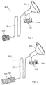
- FIGS 1 and 2 show an embodiment of a breast pump collection system 100 at two different stages of a pumping sequence.
- the breast pump collection system 100 comprises a breast shield 101 to be placed on the breast of the used and connected to a pump unit 102 via a tubing 103.
- the breast shield 101 is configured to be screwed 104 onto a collection bottle (not shown).
- a one-way valve 105 which here is a duckbill valve.
- the pump unit 102 in this embodiment is a bellows with a number of folds 200. In figure 1 the bellows is compressed. As the bellows is extracted as shown in figure 2 is created a suction to extract the milk from the breast.
- FIG 3 is shown an embodiment of a breast collection system wherein the pump unit comprises a bellows 300 with a single fold.
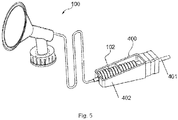
- FIGs 4 and 5 show the breast collection system 100 combined to a driving unit 400 which provides the driving motion for extracting ( figure 5 ) and compressing ( figure 4 ) the pump unit 102.
- the breast selection system and the driving unit together form a breast pump kit.
- the pump unit is simply inserted into a holder 402 wherein one end of the bellows is fixated and the other end is connected to a spindle 401 which is moved back and forth by the driving unit.
- the spindle is preferably driven by a stepping motor.
- the pump unit forms a closed system and is only connected to the exterior via the tubing. Therefore the breast collection system does not need any filters, diaphragms or the like to ensure that the air or fluid within the system cannot leak out into the mechanical parts of the driving unit, as well as the air and fluid within the collection system cannot be contaminated during use.
- FIGs 6A and 6B , and 8A and 8B illustrate embodiments of a driving unit 400 for a breast pump kit.
- the same driving unit is seen from one side in figure 6A and in a perspective view in figure 6B .
- FIG 8A-B is seen a driving unit 400 with a pump unit 102 inserted and ready for use as seen from above and in a perspective view with the top casing of the drive unit 400 removed, respectively.
- the pump unit 102 of a breast collection system is inserted into the holder 402 and thereby temporarily attached to the driving means 401 of the driving unit.
- the user can adjust and control the suction level (via the stroke length) and the frequency (via the velocity of the driving unit) of the suction sequence via a control panel 601.
- the driving units of figures 6 and 8 are configured to be used in combination with a single breast pump collection system as for example shown in figures 1-4 .
- the step motor 800 driving the spindle 401 such as to alternatingly compress and extend the bellows 102.
- FIGS 7A-B and 9A-B are shown a driving unit 700 for driving two separate breast pump collection systems at the same time or separately.
- the same driving unit is seen from one side in figure 7A and in a perspective view in figure 7B .
- a driving unit 400 with a pump unit 102 inserted and ready for use as seen from above and in a perspective view with the top casing of the drive unit 400 removed, respectively.
- the driving unit here comprises two holders 402 for detachably receiving the pump units of two collection systems.
- the driving unit may equally well be used to operate only one collection system if desired.
- the two collection systems may be operated and controlled separately and receive different control parameters by the user via the control panels 601.
- the driving unit may advantageously comprise one or two indentations or holes 701 wherein the collection bottles may be placed when not in use.
- the two step motors 800 driving the spindles 401 such as to alternatingly compress and extend the bellows 102.
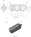
- Figures 10 and 11 illustrate an embodiment of a pump unit 102 with a bellows as seen in a cross-sectional views, and in a perspective view, respectively.
- the bellows forms the compartment of variable volume.
- At opposite end portions of the bellows are formed bottleneck or narrowing portions 1100 which are placed in corresponding holders 402 in the drive unit. As one or both holders in the drive unit are moved back and forth, the bellows is compressed and extended correspondingly.
- the shown bellows can provide near complete compression and emptying during the contraction of the compartment and approximately all air can be pressed out of the compartment. Thereby a maximal suction can be created by the subsequent extraction.
- the bellows is advantageous as it folds in and out in a well-defined given way during each cycle of extraction and contraction. In this way, the amount of suction and/or pressure can be controlled accurately by controlling or adjusting the stroke length and the frequency of the driving motion and without any need for measurements or pressure sensors. Also, the shown bellows will collapse and unfold if a certain suction is exceeded. In this way is provided an automatic safety against too high suctions as the suction cannot be increased further even if the bellows is extended further.
- the pump unit 102 shown in figures 10 and 11 can be manufactured in one single piece for example by blow moulding.
- the pump unit comprises at one end a spigot for simple connection to the tubing 103.
Landscapes
- Health & Medical Sciences (AREA)
- Heart & Thoracic Surgery (AREA)
- Life Sciences & Earth Sciences (AREA)
- Veterinary Medicine (AREA)
- Public Health (AREA)
- General Health & Medical Sciences (AREA)
- Animal Behavior & Ethology (AREA)
- Vascular Medicine (AREA)
- Hematology (AREA)
- Biomedical Technology (AREA)
- Anesthesiology (AREA)
- Engineering & Computer Science (AREA)
- Pediatric Medicine (AREA)
- External Artificial Organs (AREA)
Priority Applications (3)
| Application Number | Priority Date | Filing Date | Title |
|---|---|---|---|
| NO14787121A NO3057626T3 (cg-RX-API-DMAC7.html) | 2013-10-14 | 2014-10-09 | |
| PL14787121T PL3057626T3 (pl) | 2013-10-14 | 2014-10-09 | Pompa laktacyjna |
| EP14787121.4A EP3057626B1 (en) | 2013-10-14 | 2014-10-09 | A breast pump device |
Applications Claiming Priority (3)
| Application Number | Priority Date | Filing Date | Title |
|---|---|---|---|
| EP13188421 | 2013-10-14 | ||
| EP14787121.4A EP3057626B1 (en) | 2013-10-14 | 2014-10-09 | A breast pump device |
| PCT/EP2014/071660 WO2015055503A1 (en) | 2013-10-14 | 2014-10-09 | A breast pump device |
Publications (2)
| Publication Number | Publication Date |
|---|---|
| EP3057626A1 EP3057626A1 (en) | 2016-08-24 |
| EP3057626B1 true EP3057626B1 (en) | 2018-03-07 |
Family
ID=49356268
Family Applications (1)
| Application Number | Title | Priority Date | Filing Date |
|---|---|---|---|
| EP14787121.4A Active EP3057626B1 (en) | 2013-10-14 | 2014-10-09 | A breast pump device |
Country Status (11)
| Country | Link |
|---|---|
| US (1) | US10426876B2 (cg-RX-API-DMAC7.html) |
| EP (1) | EP3057626B1 (cg-RX-API-DMAC7.html) |
| CN (1) | CN105813664B (cg-RX-API-DMAC7.html) |
| AU (1) | AU2014336414B2 (cg-RX-API-DMAC7.html) |
| CA (1) | CA2962497C (cg-RX-API-DMAC7.html) |
| DK (1) | DK3057626T3 (cg-RX-API-DMAC7.html) |
| ES (1) | ES2672339T3 (cg-RX-API-DMAC7.html) |
| NO (1) | NO3057626T3 (cg-RX-API-DMAC7.html) |
| PL (1) | PL3057626T3 (cg-RX-API-DMAC7.html) |
| PT (1) | PT3057626T (cg-RX-API-DMAC7.html) |
| WO (1) | WO2015055503A1 (cg-RX-API-DMAC7.html) |
Families Citing this family (7)
| Publication number | Priority date | Publication date | Assignee | Title |
|---|---|---|---|---|
| GB201808647D0 (en) | 2015-11-13 | 2018-07-11 | Mitsubishi Heavy Ind Mach Systems Ltd | Communication control device, toll collection system, communication control,method and program |
| CN108883213B (zh) * | 2016-03-15 | 2022-04-08 | 皇家飞利浦有限公司 | 挤出套件 |
| DE202018006777U1 (de) | 2017-06-15 | 2022-12-14 | Chiaro Technology Limited | Brustpumpensystem |
| WO2021021223A1 (en) * | 2019-07-29 | 2021-02-04 | Babyation Inc. | Breast pump system |
| GB202004395D0 (en) | 2020-03-26 | 2020-05-13 | Chiaro Technology Ltd | Lima |
| GB2622570B (en) | 2022-08-31 | 2024-12-11 | Chiaro Technology Ltd | Breast pump |
| GB2622196A (en) | 2022-08-31 | 2024-03-13 | Chiaro Technology Ltd | Measurement system |
Family Cites Families (23)
| Publication number | Priority date | Publication date | Assignee | Title |
|---|---|---|---|---|
| US4643719A (en) * | 1984-07-19 | 1987-02-17 | Garth Geoffrey C | Manually operable aspirator |
| US4795428A (en) | 1987-03-30 | 1989-01-03 | Hwang Shyh Chyi | Therapeutic suction device |
| US5007899A (en) | 1988-02-29 | 1991-04-16 | Isg/Ag | Drive unit adapted for use with manual piston pump |
| US5165866A (en) * | 1990-12-07 | 1992-11-24 | Iwaki Co., Ltd. | Bellows pump |
| US5304129A (en) * | 1993-07-12 | 1994-04-19 | Forgach Suzanne E | Pivotable foot operated breast pump |
| US6257847B1 (en) * | 1995-08-03 | 2001-07-10 | Medela, Inc. | Diaphragm pump and pump for double-breast pumping |
| US6808517B2 (en) * | 1999-12-10 | 2004-10-26 | Medela Holding Ag | Suction sequences for a breastpump |
| NZ512318A (en) * | 2000-06-12 | 2003-01-31 | Lorne Jason Clute | Breast pump |
| AU2002232848A1 (en) * | 2000-10-20 | 2002-04-29 | Dan Carothers | Non-volatile magnetic memory device |
| US20030073951A1 (en) * | 2001-05-30 | 2003-04-17 | Morton Kevin B. | Disposable patient interface for intraductal fluid aspiration system |
| US7776008B2 (en) | 2003-08-08 | 2010-08-17 | Playtex Products, Inc. | Manual breast pump |
| US20070060873A1 (en) * | 2005-09-15 | 2007-03-15 | Katsuyuki Hiraoka | Milking apparatus |
| JP4774374B2 (ja) * | 2007-01-29 | 2011-09-14 | ピジョン株式会社 | 搾乳装置 |
| US7824363B2 (en) * | 2007-05-04 | 2010-11-02 | Medela Holding Ag | Hands-free breast pump with balanced reciprocating drive |
| US20090087860A1 (en) * | 2007-08-24 | 2009-04-02 | Todd John A | Highly sensitive system and methods for analysis of prostate specific antigen (psa) |
| JP5147572B2 (ja) | 2008-07-04 | 2013-02-20 | キヤノン株式会社 | 通信装置及びコンピュータプログラム |
| CN104147648B (zh) | 2008-07-11 | 2017-01-11 | 凯希特许有限公司 | 用于治疗创伤的手动致动的减压系统 |
| EP2324868A1 (en) * | 2009-07-28 | 2011-05-25 | Koninklijke Philips Electronics N.V. | Flexible drive for breast pump |
| PL3184136T3 (pl) * | 2010-03-25 | 2022-01-17 | New Injection Systems Ltd | Wstrzykiwacz |
| CH703813A1 (de) | 2010-09-17 | 2012-03-30 | Medela Holding Ag | Membranvakuumpumpe. |
| CN201996891U (zh) * | 2011-02-18 | 2011-10-05 | 李厚芝 | 一种妇科专用负压吸奶工具 |
| US20120265169A1 (en) * | 2011-04-14 | 2012-10-18 | Jules Sherman | Systems and methods for collecting, storing, and administering fluid from a breast |
| CN202740492U (zh) * | 2012-09-04 | 2013-02-20 | 张立美 | 医用吸奶装置 |
-
2014
- 2014-10-09 NO NO14787121A patent/NO3057626T3/no unknown
- 2014-10-09 AU AU2014336414A patent/AU2014336414B2/en active Active
- 2014-10-09 PT PT147871214T patent/PT3057626T/pt unknown
- 2014-10-09 US US15/029,109 patent/US10426876B2/en active Active
- 2014-10-09 DK DK14787121.4T patent/DK3057626T3/en active
- 2014-10-09 EP EP14787121.4A patent/EP3057626B1/en active Active
- 2014-10-09 CA CA2962497A patent/CA2962497C/en active Active
- 2014-10-09 PL PL14787121T patent/PL3057626T3/pl unknown
- 2014-10-09 CN CN201480067728.4A patent/CN105813664B/zh active Active
- 2014-10-09 WO PCT/EP2014/071660 patent/WO2015055503A1/en not_active Ceased
- 2014-10-09 ES ES14787121.4T patent/ES2672339T3/es active Active
Also Published As
| Publication number | Publication date |
|---|---|
| US10426876B2 (en) | 2019-10-01 |
| NO3057626T3 (cg-RX-API-DMAC7.html) | 2018-08-04 |
| AU2014336414B2 (en) | 2018-09-27 |
| DK3057626T3 (en) | 2018-06-14 |
| PT3057626T (pt) | 2018-06-08 |
| AU2014336414A1 (en) | 2016-06-02 |
| ES2672339T3 (es) | 2018-06-13 |
| US20160256617A1 (en) | 2016-09-08 |
| CN105813664A (zh) | 2016-07-27 |
| CA2962497C (en) | 2020-06-23 |
| EP3057626A1 (en) | 2016-08-24 |
| WO2015055503A1 (en) | 2015-04-23 |
| CN105813664B (zh) | 2018-10-23 |
| PL3057626T3 (pl) | 2018-08-31 |
| CA2962497A1 (en) | 2015-04-23 |
Similar Documents
| Publication | Publication Date | Title |
|---|---|---|
| EP3057626B1 (en) | A breast pump device | |
| US7785305B2 (en) | System for collecting breast milk from a human breast | |
| CA2451171C (en) | System for a portable hands-free breast pump and method of using the same | |
| US10286130B2 (en) | Breast pump | |
| JP2023036746A (ja) | 搾乳アセンブリ及び方法 | |
| US11147905B2 (en) | Breast pump | |
| AU2002316283A1 (en) | System for a portable hands-free breast pump and method of using the same | |
| US20170080134A1 (en) | Breast pump system and methods | |
| WO2005067997A1 (en) | Breast pump | |
| TWM552354U (zh) | 一種三通部件及具備該三通部件的吸奶器 | |
| US11116880B2 (en) | Manual breast pump | |
| GB2138686A (en) | Breast milk extraction apparatus | |
| US20210154383A1 (en) | Single-use breastmilk collection device and related system and method | |
| RU2575670C2 (ru) | Грудной молокоотсос | |
| CN118987391A (zh) | 一种能够挤压的吸奶器 | |
| CA2625100A1 (en) | System for a portable hands-free breast pump and method of using the same | |
| CN201643107U (zh) | 医用吸奶器 |
Legal Events
| Date | Code | Title | Description |
|---|---|---|---|
| PUAI | Public reference made under article 153(3) epc to a published international application that has entered the european phase |
Free format text: ORIGINAL CODE: 0009012 |
|
| 17P | Request for examination filed |
Effective date: 20160517 |
|
| AK | Designated contracting states |
Kind code of ref document: A1 Designated state(s): AL AT BE BG CH CY CZ DE DK EE ES FI FR GB GR HR HU IE IS IT LI LT LU LV MC MK MT NL NO PL PT RO RS SE SI SK SM TR |
|
| AX | Request for extension of the european patent |
Extension state: BA ME |
|
| DAX | Request for extension of the european patent (deleted) | ||
| STAA | Information on the status of an ep patent application or granted ep patent |
Free format text: STATUS: EXAMINATION IS IN PROGRESS |
|
| 17Q | First examination report despatched |
Effective date: 20170306 |
|
| GRAP | Despatch of communication of intention to grant a patent |
Free format text: ORIGINAL CODE: EPIDOSNIGR1 |
|
| STAA | Information on the status of an ep patent application or granted ep patent |
Free format text: STATUS: GRANT OF PATENT IS INTENDED |
|
| INTG | Intention to grant announced |
Effective date: 20171012 |
|
| RIN1 | Information on inventor provided before grant (corrected) |
Inventor name: HANSEN, JAN ERIK VEST |
|
| INTG | Intention to grant announced |
Effective date: 20171019 |
|
| GRAS | Grant fee paid |
Free format text: ORIGINAL CODE: EPIDOSNIGR3 |
|
| GRAA | (expected) grant |
Free format text: ORIGINAL CODE: 0009210 |
|
| STAA | Information on the status of an ep patent application or granted ep patent |
Free format text: STATUS: THE PATENT HAS BEEN GRANTED |
|
| AK | Designated contracting states |
Kind code of ref document: B1 Designated state(s): AL AT BE BG CH CY CZ DE DK EE ES FI FR GB GR HR HU IE IS IT LI LT LU LV MC MK MT NL NO PL PT RO RS SE SI SK SM TR |
|
| REG | Reference to a national code |
Ref country code: GB Ref legal event code: FG4D |
|
| REG | Reference to a national code |
Ref country code: CH Ref legal event code: EP Ref country code: AT Ref legal event code: REF Ref document number: 975868 Country of ref document: AT Kind code of ref document: T Effective date: 20180315 |
|
| REG | Reference to a national code |
Ref country code: IE Ref legal event code: FG4D |
|
| REG | Reference to a national code |
Ref country code: DE Ref legal event code: R096 Ref document number: 602014022112 Country of ref document: DE |
|
| REG | Reference to a national code |
Ref country code: PT Ref legal event code: SC4A Ref document number: 3057626 Country of ref document: PT Date of ref document: 20180608 Kind code of ref document: T Free format text: AVAILABILITY OF NATIONAL TRANSLATION Effective date: 20180604 |
|
| REG | Reference to a national code |
Ref country code: NO Ref legal event code: T2 Effective date: 20180307 |
|
| REG | Reference to a national code |
Ref country code: ES Ref legal event code: FG2A Ref document number: 2672339 Country of ref document: ES Kind code of ref document: T3 Effective date: 20180613 Ref country code: NL Ref legal event code: FP |
|
| REG | Reference to a national code |
Ref country code: DK Ref legal event code: T3 Effective date: 20180607 |
|
| REG | Reference to a national code |
Ref country code: CH Ref legal event code: NV Representative=s name: MICHELI AND CIE SA, CH |
|
| REG | Reference to a national code |
Ref country code: SE Ref legal event code: TRGR |
|
| REG | Reference to a national code |
Ref country code: LT Ref legal event code: MG4D |
|
| PG25 | Lapsed in a contracting state [announced via postgrant information from national office to epo] |
Ref country code: LT Free format text: LAPSE BECAUSE OF FAILURE TO SUBMIT A TRANSLATION OF THE DESCRIPTION OR TO PAY THE FEE WITHIN THE PRESCRIBED TIME-LIMIT Effective date: 20180307 Ref country code: CY Free format text: LAPSE BECAUSE OF FAILURE TO SUBMIT A TRANSLATION OF THE DESCRIPTION OR TO PAY THE FEE WITHIN THE PRESCRIBED TIME-LIMIT Effective date: 20180307 Ref country code: HR Free format text: LAPSE BECAUSE OF FAILURE TO SUBMIT A TRANSLATION OF THE DESCRIPTION OR TO PAY THE FEE WITHIN THE PRESCRIBED TIME-LIMIT Effective date: 20180307 |
|
| PG25 | Lapsed in a contracting state [announced via postgrant information from national office to epo] |
Ref country code: RS Free format text: LAPSE BECAUSE OF FAILURE TO SUBMIT A TRANSLATION OF THE DESCRIPTION OR TO PAY THE FEE WITHIN THE PRESCRIBED TIME-LIMIT Effective date: 20180307 Ref country code: BG Free format text: LAPSE BECAUSE OF FAILURE TO SUBMIT A TRANSLATION OF THE DESCRIPTION OR TO PAY THE FEE WITHIN THE PRESCRIBED TIME-LIMIT Effective date: 20180607 Ref country code: LV Free format text: LAPSE BECAUSE OF FAILURE TO SUBMIT A TRANSLATION OF THE DESCRIPTION OR TO PAY THE FEE WITHIN THE PRESCRIBED TIME-LIMIT Effective date: 20180307 |
|
| REG | Reference to a national code |
Ref country code: FR Ref legal event code: PLFP Year of fee payment: 5 |
|
| PG25 | Lapsed in a contracting state [announced via postgrant information from national office to epo] |
Ref country code: AL Free format text: LAPSE BECAUSE OF FAILURE TO SUBMIT A TRANSLATION OF THE DESCRIPTION OR TO PAY THE FEE WITHIN THE PRESCRIBED TIME-LIMIT Effective date: 20180307 Ref country code: RO Free format text: LAPSE BECAUSE OF FAILURE TO SUBMIT A TRANSLATION OF THE DESCRIPTION OR TO PAY THE FEE WITHIN THE PRESCRIBED TIME-LIMIT Effective date: 20180307 Ref country code: EE Free format text: LAPSE BECAUSE OF FAILURE TO SUBMIT A TRANSLATION OF THE DESCRIPTION OR TO PAY THE FEE WITHIN THE PRESCRIBED TIME-LIMIT Effective date: 20180307 |
|
| REG | Reference to a national code |
Ref country code: GR Ref legal event code: EP Ref document number: 20180401491 Country of ref document: GR Effective date: 20181031 |
|
| PG25 | Lapsed in a contracting state [announced via postgrant information from national office to epo] |
Ref country code: SK Free format text: LAPSE BECAUSE OF FAILURE TO SUBMIT A TRANSLATION OF THE DESCRIPTION OR TO PAY THE FEE WITHIN THE PRESCRIBED TIME-LIMIT Effective date: 20180307 Ref country code: SM Free format text: LAPSE BECAUSE OF FAILURE TO SUBMIT A TRANSLATION OF THE DESCRIPTION OR TO PAY THE FEE WITHIN THE PRESCRIBED TIME-LIMIT Effective date: 20180307 |
|
| REG | Reference to a national code |
Ref country code: DE Ref legal event code: R097 Ref document number: 602014022112 Country of ref document: DE |
|
| PLBE | No opposition filed within time limit |
Free format text: ORIGINAL CODE: 0009261 |
|
| STAA | Information on the status of an ep patent application or granted ep patent |
Free format text: STATUS: NO OPPOSITION FILED WITHIN TIME LIMIT |
|
| 26N | No opposition filed |
Effective date: 20181210 |
|
| PG25 | Lapsed in a contracting state [announced via postgrant information from national office to epo] |
Ref country code: SI Free format text: LAPSE BECAUSE OF FAILURE TO SUBMIT A TRANSLATION OF THE DESCRIPTION OR TO PAY THE FEE WITHIN THE PRESCRIBED TIME-LIMIT Effective date: 20180307 |
|
| PG25 | Lapsed in a contracting state [announced via postgrant information from national office to epo] |
Ref country code: MC Free format text: LAPSE BECAUSE OF FAILURE TO SUBMIT A TRANSLATION OF THE DESCRIPTION OR TO PAY THE FEE WITHIN THE PRESCRIBED TIME-LIMIT Effective date: 20180307 Ref country code: LU Free format text: LAPSE BECAUSE OF NON-PAYMENT OF DUE FEES Effective date: 20181009 |
|
| PG25 | Lapsed in a contracting state [announced via postgrant information from national office to epo] |
Ref country code: MT Free format text: LAPSE BECAUSE OF NON-PAYMENT OF DUE FEES Effective date: 20181009 |
|
| PG25 | Lapsed in a contracting state [announced via postgrant information from national office to epo] |
Ref country code: TR Free format text: LAPSE BECAUSE OF FAILURE TO SUBMIT A TRANSLATION OF THE DESCRIPTION OR TO PAY THE FEE WITHIN THE PRESCRIBED TIME-LIMIT Effective date: 20180307 |
|
| PG25 | Lapsed in a contracting state [announced via postgrant information from national office to epo] |
Ref country code: MK Free format text: LAPSE BECAUSE OF NON-PAYMENT OF DUE FEES Effective date: 20180307 Ref country code: HU Free format text: LAPSE BECAUSE OF FAILURE TO SUBMIT A TRANSLATION OF THE DESCRIPTION OR TO PAY THE FEE WITHIN THE PRESCRIBED TIME-LIMIT; INVALID AB INITIO Effective date: 20141009 |
|
| PG25 | Lapsed in a contracting state [announced via postgrant information from national office to epo] |
Ref country code: IS Free format text: LAPSE BECAUSE OF FAILURE TO SUBMIT A TRANSLATION OF THE DESCRIPTION OR TO PAY THE FEE WITHIN THE PRESCRIBED TIME-LIMIT Effective date: 20180707 |
|
| REG | Reference to a national code |
Ref country code: NO Ref legal event code: CHAD Owner name: COLOLACT A/S, DK Ref country code: NO Ref legal event code: CREP Representative=s name: PLOUGMANN VINGTOFT, POSTBOKS 1003 SENTRUM, 0104 |
|
| REG | Reference to a national code |
Ref country code: CH Ref legal event code: NV Representative=s name: BOVARD SA NEUCHATEL CONSEILS EN PROPRIETE INTE, CH Ref country code: CH Ref legal event code: PUE Owner name: COLOLACT A/S, DK Free format text: FORMER OWNER: VESUCTA APS, DK |
|
| REG | Reference to a national code |
Ref country code: DE Ref legal event code: R081 Ref document number: 602014022112 Country of ref document: DE Owner name: COLOLACT A/S, DK Free format text: FORMER OWNER: VESUCTA APS, AARHUS N, DK |
|
| REG | Reference to a national code |
Ref country code: FI Ref legal event code: PCE Owner name: COLOLACT A/S |
|
| REG | Reference to a national code |
Ref country code: ES Ref legal event code: PC2A Owner name: COLOLACT A/S Effective date: 20210204 |
|
| REG | Reference to a national code |
Ref country code: GB Ref legal event code: 732E Free format text: REGISTERED BETWEEN 20210121 AND 20210127 |
|
| REG | Reference to a national code |
Ref country code: NL Ref legal event code: PD Owner name: COLOLACT A/S; DK Free format text: DETAILS ASSIGNMENT: CHANGE OF OWNER(S), ASSIGNMENT; FORMER OWNER NAME: VESUCTA APS Effective date: 20210204 |
|
| REG | Reference to a national code |
Ref country code: BE Ref legal event code: PD Owner name: COLOLACT A/S; DK Free format text: DETAILS ASSIGNMENT: CHANGE OF OWNER(S), ASSIGNMENT Effective date: 20210209 |
|
| REG | Reference to a national code |
Ref country code: AT Ref legal event code: UEP Ref document number: 975868 Country of ref document: AT Kind code of ref document: T Effective date: 20180307 |
|
| REG | Reference to a national code |
Ref country code: AT Ref legal event code: PC Ref document number: 975868 Country of ref document: AT Kind code of ref document: T Owner name: COLOLACT A/S, DK Effective date: 20220715 |
|
| P01 | Opt-out of the competence of the unified patent court (upc) registered |
Effective date: 20230517 |
|
| PGFP | Annual fee paid to national office [announced via postgrant information from national office to epo] |
Ref country code: PT Payment date: 20250916 Year of fee payment: 12 |
|
| PGFP | Annual fee paid to national office [announced via postgrant information from national office to epo] |
Ref country code: CZ Payment date: 20250915 Year of fee payment: 12 |
|
| REG | Reference to a national code |
Ref country code: CH Ref legal event code: U11 Free format text: ST27 STATUS EVENT CODE: U-0-0-U10-U11 (AS PROVIDED BY THE NATIONAL OFFICE) Effective date: 20251101 |
|
| PGFP | Annual fee paid to national office [announced via postgrant information from national office to epo] |
Ref country code: NL Payment date: 20251016 Year of fee payment: 12 |
|
| PGFP | Annual fee paid to national office [announced via postgrant information from national office to epo] |
Ref country code: DE Payment date: 20251020 Year of fee payment: 12 |
|
| PGFP | Annual fee paid to national office [announced via postgrant information from national office to epo] |
Ref country code: GB Payment date: 20251016 Year of fee payment: 12 |
|
| PGFP | Annual fee paid to national office [announced via postgrant information from national office to epo] |
Ref country code: NO Payment date: 20251017 Year of fee payment: 12 |
|
| PGFP | Annual fee paid to national office [announced via postgrant information from national office to epo] |
Ref country code: AT Payment date: 20251016 Year of fee payment: 12 |
|
| PGFP | Annual fee paid to national office [announced via postgrant information from national office to epo] |
Ref country code: FI Payment date: 20251020 Year of fee payment: 12 Ref country code: DK Payment date: 20251016 Year of fee payment: 12 Ref country code: IT Payment date: 20251020 Year of fee payment: 12 |
|
| PGFP | Annual fee paid to national office [announced via postgrant information from national office to epo] |
Ref country code: FR Payment date: 20251016 Year of fee payment: 12 |
|
| PGFP | Annual fee paid to national office [announced via postgrant information from national office to epo] |
Ref country code: BE Payment date: 20251020 Year of fee payment: 12 Ref country code: GR Payment date: 20251020 Year of fee payment: 12 |
|
| PGFP | Annual fee paid to national office [announced via postgrant information from national office to epo] |
Ref country code: CH Payment date: 20251101 Year of fee payment: 12 Ref country code: SE Payment date: 20251015 Year of fee payment: 12 |
|
| PGFP | Annual fee paid to national office [announced via postgrant information from national office to epo] |
Ref country code: IE Payment date: 20251020 Year of fee payment: 12 |
|
| PGFP | Annual fee paid to national office [announced via postgrant information from national office to epo] |
Ref country code: PL Payment date: 20251006 Year of fee payment: 12 |
|
| REG | Reference to a national code |
Ref country code: CH Ref legal event code: R18 Free format text: ST27 STATUS EVENT CODE: U-0-0-R10-R18 (AS PROVIDED BY THE NATIONAL OFFICE) Effective date: 20260209 |
|
| REG | Reference to a national code |
Ref country code: CH Ref legal event code: R18 Free format text: ST27 STATUS EVENT CODE: U-0-0-R10-R18 (AS PROVIDED BY THE NATIONAL OFFICE) Effective date: 20260320 |
|
| PGFP | Annual fee paid to national office [announced via postgrant information from national office to epo] |
Ref country code: ES Payment date: 20260109 Year of fee payment: 12 |