EP3056239B1 - Cathéter à ballonnet - Google Patents
Cathéter à ballonnet Download PDFInfo
- Publication number
- EP3056239B1 EP3056239B1 EP16154040.6A EP16154040A EP3056239B1 EP 3056239 B1 EP3056239 B1 EP 3056239B1 EP 16154040 A EP16154040 A EP 16154040A EP 3056239 B1 EP3056239 B1 EP 3056239B1
- Authority
- EP
- European Patent Office
- Prior art keywords
- channel
- channel length
- length portion
- section
- catheter
- Prior art date
- Legal status (The legal status is an assumption and is not a legal conclusion. Google has not performed a legal analysis and makes no representation as to the accuracy of the status listed.)
- Active
Links
- 239000012530 fluid Substances 0.000 claims description 41
- 230000005540 biological transmission Effects 0.000 claims description 34
- 230000007704 transition Effects 0.000 claims description 32
- 239000004033 plastic Substances 0.000 claims description 5
- 229920003023 plastic Polymers 0.000 claims description 5
- 229920001343 polytetrafluoroethylene Polymers 0.000 claims description 5
- 239000004810 polytetrafluoroethylene Substances 0.000 claims description 5
- 239000013013 elastic material Substances 0.000 claims description 3
- 239000000463 material Substances 0.000 claims description 3
- 229920001971 elastomer Polymers 0.000 claims description 2
- 238000007789 sealing Methods 0.000 description 12
- KWGRBVOPPLSCSI-WPRPVWTQSA-N (-)-ephedrine Chemical compound CN[C@@H](C)[C@H](O)C1=CC=CC=C1 KWGRBVOPPLSCSI-WPRPVWTQSA-N 0.000 description 8
- 238000006073 displacement reaction Methods 0.000 description 8
- 230000000694 effects Effects 0.000 description 8
- 239000002872 contrast media Substances 0.000 description 6
- 229920001296 polysiloxane Polymers 0.000 description 4
- 238000004873 anchoring Methods 0.000 description 2
- -1 polytetrafluoroethylene Polymers 0.000 description 2
- 238000000926 separation method Methods 0.000 description 2
- 238000004804 winding Methods 0.000 description 2
- 241001465754 Metazoa Species 0.000 description 1
- 230000008602 contraction Effects 0.000 description 1
- 230000007423 decrease Effects 0.000 description 1
- 230000001934 delay Effects 0.000 description 1
- 239000011796 hollow space material Substances 0.000 description 1
- 230000003993 interaction Effects 0.000 description 1
- 239000004816 latex Substances 0.000 description 1
- 229920000126 latex Polymers 0.000 description 1
- 239000002184 metal Substances 0.000 description 1
- 238000000034 method Methods 0.000 description 1
- 230000035515 penetration Effects 0.000 description 1
- 230000006641 stabilisation Effects 0.000 description 1
- 238000011105 stabilization Methods 0.000 description 1
- 239000000126 substance Substances 0.000 description 1
- 230000001225 therapeutic effect Effects 0.000 description 1
Images


Classifications
-
- A—HUMAN NECESSITIES
- A61—MEDICAL OR VETERINARY SCIENCE; HYGIENE
- A61M—DEVICES FOR INTRODUCING MEDIA INTO, OR ONTO, THE BODY; DEVICES FOR TRANSDUCING BODY MEDIA OR FOR TAKING MEDIA FROM THE BODY; DEVICES FOR PRODUCING OR ENDING SLEEP OR STUPOR
- A61M25/00—Catheters; Hollow probes
- A61M25/10—Balloon catheters
- A61M25/1018—Balloon inflating or inflation-control devices
- A61M25/10184—Means for controlling or monitoring inflation or deflation
- A61M25/10185—Valves
-
- A—HUMAN NECESSITIES
- A61—MEDICAL OR VETERINARY SCIENCE; HYGIENE
- A61M—DEVICES FOR INTRODUCING MEDIA INTO, OR ONTO, THE BODY; DEVICES FOR TRANSDUCING BODY MEDIA OR FOR TAKING MEDIA FROM THE BODY; DEVICES FOR PRODUCING OR ENDING SLEEP OR STUPOR
- A61M25/00—Catheters; Hollow probes
- A61M25/0067—Catheters; Hollow probes characterised by the distal end, e.g. tips
- A61M25/0074—Dynamic characteristics of the catheter tip, e.g. openable, closable, expandable or deformable
- A61M25/0075—Valve means
-
- A—HUMAN NECESSITIES
- A61—MEDICAL OR VETERINARY SCIENCE; HYGIENE
- A61M—DEVICES FOR INTRODUCING MEDIA INTO, OR ONTO, THE BODY; DEVICES FOR TRANSDUCING BODY MEDIA OR FOR TAKING MEDIA FROM THE BODY; DEVICES FOR PRODUCING OR ENDING SLEEP OR STUPOR
- A61M39/00—Tubes, tube connectors, tube couplings, valves, access sites or the like, specially adapted for medical use
- A61M39/22—Valves or arrangement of valves
- A61M39/24—Check- or non-return valves
-
- A—HUMAN NECESSITIES
- A61—MEDICAL OR VETERINARY SCIENCE; HYGIENE
- A61M—DEVICES FOR INTRODUCING MEDIA INTO, OR ONTO, THE BODY; DEVICES FOR TRANSDUCING BODY MEDIA OR FOR TAKING MEDIA FROM THE BODY; DEVICES FOR PRODUCING OR ENDING SLEEP OR STUPOR
- A61M25/00—Catheters; Hollow probes
- A61M2025/0008—Catheters; Hollow probes having visible markings on its surface, i.e. visible to the naked eye, for any purpose, e.g. insertion depth markers, rotational markers or identification of type
-
- A—HUMAN NECESSITIES
- A61—MEDICAL OR VETERINARY SCIENCE; HYGIENE
- A61M—DEVICES FOR INTRODUCING MEDIA INTO, OR ONTO, THE BODY; DEVICES FOR TRANSDUCING BODY MEDIA OR FOR TAKING MEDIA FROM THE BODY; DEVICES FOR PRODUCING OR ENDING SLEEP OR STUPOR
- A61M25/00—Catheters; Hollow probes
- A61M2025/0018—Catheters; Hollow probes having a plug, e.g. an inflatable plug for closing catheter lumens
-
- A—HUMAN NECESSITIES
- A61—MEDICAL OR VETERINARY SCIENCE; HYGIENE
- A61M—DEVICES FOR INTRODUCING MEDIA INTO, OR ONTO, THE BODY; DEVICES FOR TRANSDUCING BODY MEDIA OR FOR TAKING MEDIA FROM THE BODY; DEVICES FOR PRODUCING OR ENDING SLEEP OR STUPOR
- A61M25/00—Catheters; Hollow probes
- A61M25/01—Introducing, guiding, advancing, emplacing or holding catheters
- A61M25/0105—Steering means as part of the catheter or advancing means; Markers for positioning
- A61M25/0108—Steering means as part of the catheter or advancing means; Markers for positioning using radio-opaque or ultrasound markers
Definitions
- the present invention relates to a balloon catheter comprising a catheter line, an expandable balloon attached to it, which borders a balloon interior, and a connection device connected to the catheter line, which has at least a first connection for the supply of fluid, in particular air, for filling the balloon, wherein in the catheter line at least one first channel extends, which is in fluidic connection at its proximal longitudinal end with the first connection and which is in fluidic connection at its distal longitudinal end with the balloon interior, the first channel having a first channel length section and one in it distal direction with a transition adjoining second channel length section and wherein the catheter line is made of elastic material at least along these channel length sections and along the transition, the balloon catheter at least a first, preferably designed as a ball has formed, valve element that is inserted into the first channel, wherein, preferably with each relaxed wall of the catheter line, the area of the hollow cross-section of the first channel in the second channel length section smaller than the area of the hollow cross section of the first channel in the first channel length section and smaller than is the area
- a balloon catheter is from the post-published German patent application DE 10 2013 110 989 known to the applicant.
- the known balloon catheter has a number of advantages, rapid emptying of the balloon can only be achieved by cutting off a rear length section of the catheter line that encloses the valve.
- the known balloon catheter also has a comparatively complex structure with regard to the spring check valve contained therein.
- a balloon catheter of the generic type is known from the prior art U.S. 3,982,544 A known.
- DE 10 2012 109 894 A1 discloses a balloon catheter and a method for its use, wherein the balloon catheter has a connection device and a valve in the catheter line and it is proposed that after balloon expansion achieved by means of fluid supply, the catheter line between the valve and the connection device is severed.
- US 2012/0035588 A1 discloses a balloon catheter for the delivery of therapeutic substances.
- the present invention is based on the object of advantageously developing a generic balloon catheter, see above that in particular one or more of the disadvantages described above are to be avoided.
- the force transmission device is attached to the first valve element and extends from the first valve element in the proximal direction through the first channel and further through the connection device to a handle, wherein by means of movement of the handle to the connecting device, the first valve element can be moved from the first length of the channel into the second length of channel, with elastic expansion of the wall of the catheter line there.
- the reference to a relaxed state of the wall of the catheter line bordering the first channel relates to the elastic property of its material.
- the wall of the catheter line is relaxed when it is not subject to any deformation stress.
- the term first channel denotes a cavity extending in the catheter line.
- the area of the The hollow cross section of the first channel accordingly only comprises the area of the cross section of the cavity and not the area of the cross section of the wall of the catheter line surrounding the cavity.
- the mentioned hollow cross section or cross section is oriented in particular perpendicular to the local longitudinal direction of the catheter line.
- the mentioned cross section of the first valve element is the largest cross section oriented perpendicular to the longitudinal direction of the catheter line. If the valve element is designed as a ball, the cross section and its area are determined by the diameter.
- the force transmission device is preferably a wire connection, as will be described below.
- proximal and distal are used in the meaning customary for balloon catheters.
- proximal denotes the side facing a user or the connection device or a respective location of a component of the balloon catheter being considered closer to a user (e.g. surgeon), while the term distal denotes the side farther away from the user or one from the user more distant place.
- proximal direction is understood to mean a direction pointing towards the user and the distal direction is a direction pointing away from the user.
- the invention enables the valve element to be moved back and forth several times in the first channel of the catheter line in its longitudinal direction by means of the force transmission device, which could also be referred to as a valve slide.
- the valve in the first channel formed in the interaction of the valve element with the two channel length sections and their transition between them can thereby be specifically closed and opened again several times.
- the hollow cross-section in the first channel length section is dimensioned so large that fluid, preferably air, for filling the balloon, can flow past the first valve element in the distal direction.
- the area of the hollow cross-section of the first channel in the first channel length section in particular with regard to the surface area, can be selected to be so large that a gap results between the first valve element and the wall of the catheter line bordering the first channel even when the ambient pressure is active therein.
- the area of the hollow cross-section of the first channel in the first channel length section in particular with regard to the surface area, could be selected to be approximately the same size as or slightly smaller than the area of the maximum cross-section of the first valve element, which is oriented perpendicular to the longitudinal direction of the catheter line, so that there is a gap between them is only formed in the first channel when a certain pressure above ambient pressure is reached.
- the valve element When the valve element enters the second duct length section or the transition between the first and second duct length section, it seals the first duct.
- the valve element thus forms a valve with the two duct length sections and the transition of the first duct in between, which valve can be opened and closed quickly and repeatedly if required by means of the force transmission device (valve slide).
- the first valve element is preferably tapered on its distal side in the distal direction, for example conical or rounded. This already favors the sealing effect in the transition.
- the force transmission device can preferably be a wire connection composed, for example, of several wire sections.
- the wire connection is preferably designed to be tensile and shear-resistant in relation to the forces occurring during operation.
- the hollow cross section in the first channel length section of the first channel is preferably slightly larger than the cross section of the wire connection, so that fluid can flow through it and nevertheless an at least substantially concentric guidance of the wire connection in the first channel results. This applies accordingly to a passage for the power transmission device and for fluid through the connection device.
- the force transmission device is designed to be sufficiently rigid to exert a compressive force on the first valve element in the longitudinal direction of the catheter line, which is sufficient to push the first valve element into the second length of the canal and thereby elastically expand the wall of the catheter line in the second length of canal. If the valve element is withdrawn again in the proximal direction from the second channel length section by means of the force transmission device, the wall of the catheter line is elastically deformed back there.
- the area of the hollow cross section of the first channel at each point in the second channel length section is smaller than the area of the hollow cross section of the first channel at each location in the first channel length section and smaller than the area of the largest cross section oriented perpendicular to the longitudinal direction of the catheter line of the first valve element.
- the hollow cross-section can, for example, be rounded (in particular circular or oval) or with polygonal edges. It is preferred that, particularly when the wall of the catheter line is relaxed, the hollow cross-section of the first channel is uniform or essentially uniform in the first channel length section and the hollow cross-section of the first channel in the second channel length section which differs from this in terms of area is also uniform or essentially uniform therein.
- a uniform or essentially uniform hollow cross section within the respective channel length sections is not mandatory, but the invention also includes the possibility that the hollow cross section varies within or along a respective channel length section.
- the first channel uniformly has a circular hollow cross section in the first channel length section with a first channel diameter uniform in the first channel length section and uniformly a circular hollow cross section with a second channel diameter uniform in the second channel length section has, wherein the second channel diameter is smaller than the first channel diameter and smaller than the diameter of the first valve element, in particular designed as a sphere or hemisphere.
- the first channel diameter in the first channel length section is greater than or equal to or smaller than the diameter of the first valve element designed as a sphere or hemisphere.
- the hollow cross section of the first channel tapers continuously, in particular conically, in the distal direction. This favors reliable opening and closing of the valve formed.
- a first stop is fastened or formed on the power transmission device and that a first counter-stop is fastened or formed on the connection device and that the handle piece can be advanced to the connection device up to a distal end position, upon reaching the first Stop, limiting the displacement in a form-fitting manner, occurs against the first counter-stop and the first valve element is located in the second channel length section.
- a second stop is attached or formed on the power transmission device and a second counterstop is attached or formed on the connection device and that the handle piece can be pulled away from the connection device up to a proximal end position, upon reaching the second stop , positively limiting the pulling movement, occurs against the second counter-stop and the first valve element is located in the first duct length section.
- the balloon catheter has a second, in particular cylindrical, valve element which adjoins the first valve element on its proximal side, with provision being made in particular that the diameter of the second valve element corresponds to the diameter of the first valve element, with, when the handle is in the distal end position, the second valve element is wholly or partially in the second channel length section of the first channel.
- the sealing effect can be improved even further by means of the second valve element.
- the proximal longitudinal end of the second channel length section is spaced apart from the connection device in the distal direction.
- the outer surface of the catheter line is made of plastic, such as polytetrafluoroethylene (PTFE), or of rubber, at least along the first and second channel length sections and the transition.
- PTFE polytetrafluoroethylene
- the catheter line is thicker in its length area corresponding to the first length of the channel than in its length area corresponding to the second length of the channel. It is considered expedient that the catheter line, at least in a partial length section including the first length of the channel, the transition and the second length of the channel, is formed, or as a whole in one piece.
- the transition with the tapering hollow cross-section by pulling the catheter line in the heated state up to a certain position through a sleeve-like, tapering tool. The position of the transition is determined by how far the catheter lead is pulled through the tool.
- the first channel length section and the second channel length section can, depending on the requirements, can be chosen in their respective length.
- first channel length section extends from the transition in the proximal direction to the proximal longitudinal end of the catheter line. It is preferred that the second channel length section extends from the transition in the distal direction to a closure of the first channel which is arranged distally with respect to a passage from the first channel to the interior of the balloon.
- a second marking in particular a ring in a second color
- the second marking can indicate a preferred position of the catheter line at which it is to be cut through in order to be able to reliably deflate the balloon even after the connection device has been separated. If, which is preferred, the anti-kink sleeve is opaque, will the second marking is initially covered by the anti-kink sleeve, which improves the functional reliability of the balloon catheter.
- a filling device which comprises a hollow needle and a housing adjoining it, with at least one connection for supplying fluid for filling the balloon, in particular a connection for detachable attachment of a syringe, being formed on the filling device and the hollow needles are in fluidic connection with one another by means of a fluid passage extending in the housing and that the outer cross section of the hollow needle is slightly larger than the hollow cross section of the first channel in the second channel length section.
- the connection device has a third connection and that the catheter line has a second channel which connects the third connection to an opening in the catheter line at its distal end.
- the term second channel denotes a further cavity extending in the catheter line.
- the second channel can be used, for example, to guide a guide wire through.
- the second channel can also serve for the passage of contrast medium.
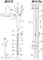
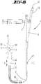
- a balloon catheter 1 according to the invention is presented according to a preferred exemplary embodiment.
- This comprises a catheter line 2, an expandable balloon 3, which borders a balloon interior 4 and is attached to the catheter line 2 in the vicinity of its distal longitudinal end 5.
- the balloon catheter 1 comprises a connection device 6, which is firmly connected to the catheter line 2 at its distal longitudinal end.
- the connection device 6 has a first connection 7 on the side, a second connection 8 and a third connection 9 pointing proximally.
- the connection 7 serves to supply a pressurized fluid, for example air, in order to inflate the balloon 3.
- a syringe 10 is connected to the connection 7 by means of a screw or plug connection.
- the second connection 8 serves to lead through a force transmission device 11, which is described in more detail below and which could also be referred to as a valve slide.
- the connector 9 can be used for passing a guide wire 12 (cf. Figure 8 ) serve.
- a contrast agent attachment 13, known per se, can be connected for the passage of contrast agent.
- the Connection device 6 will be described in greater detail later with reference to FIG Figure 5 described.
- the catheter line 2 is at its proximal longitudinal end 17 by means of an in Figure 1 Connection 14, not shown in more detail, is firmly connected to the distal end of the connection device 6.
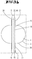
- the balloon envelope 20 is formed from a tube piece made of latex, the two longitudinal ends of which are adapted to form a seal against the catheter tube 2 from the outside by means of a wire winding 21 each.
- the second channel 16 extends continuously from the proximal longitudinal end 17 to an end opening 22 at the distal longitudinal end 5 of the catheter line 2.
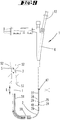
- Figure 2 shows that in the connection device 6 the first connection 7 is in fluidic connection with the first channel 15 by means of a fluid passage 23.
- the distal longitudinal end 26 of the first channel 15 is in fluidic connection with the balloon interior 4.
- the first channel 15 has a first channel length section 27 and a transition thereon in the distal direction 28 subsequent second channel length section 29.
- the first channel length section 27 and the second channel length section 29 are only partially visible.
- the first channel length section 27 extends from the transition 28 in the proximal direction to the proximal longitudinal end 17 of the catheter line 2 and the second channel length section 29 extends from the transition 28 in the distal direction to the distal longitudinal end 26 of the first channel 15.
- the first channel length section 27 proceeding from the transition 28 has a shorter length and / or that the second channel length section 29 proceeding from the transition 28 has a shorter length.
- the proximal longitudinal end 17 of the catheter line 2 is at the same time the proximal longitudinal end 17 of the first channel 15.
- the balloon catheter 2 has a first valve element 24, which in the example is designed as a ball.
- a second valve element 25 is additionally provided, which is a cylindrical sleeve.
- the valve elements 24, 25 are each fastened to the force transmission device 11 and can be displaced by means of this in the longitudinal direction L of the catheter line 2 in the first channel 15.
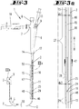
- the diameter of the first valve element 24, ie the ball in the example, is in Figure 4a denoted by dv1.
- the outer diameter of the second valve element 25, ie the sleeve in the example, is designated there by dv2.
- the diameters dv1 and dv2 are selected to be the same size.
- the catheter line 2 is made in one piece from elastic plastic.
- the first channel 15 in the first channel length section 27 has a circular cross section with a channel diameter dk1 that is uniform in the first channel length section 27 (cf. Figure 6 ) and the first channel 15 has in the second channel length section 29 (cf. Figure 7 ) a circular cross section with a second channel diameter dk2 which is uniform in the second channel length section 29 and which is smaller than the diameter dk1.
- the first channel diameter dk1 in the exemplary embodiment shown is greater than the corresponding diameters dv1 and dv2.
- the diameter dk2 is smaller than the diameters dv1 and dv2, this difference in diameter being selected so that the diameter dk2 can be expanded to their diameter dv1 or dv2 when the valve elements 24, 25 penetrate.
- the diameter continuously decreases from the diameter dk1 to the diameter dk2.
- valve elements 24, 25 are moved from the first channel length section 27 in the distal direction, at least until the distal front valve element 24 presses against the wall 30 in the transition 28, the first channel 15 is sealed.
- This sealing can be reinforced by the first valve element 24 and at least a length section of the second valve element 25 being pushed forward into the second channel length section 29.
- pressurized fluid in the example air supplied through the connection 7 cannot flow past the valve elements 24, 25 in the distal direction in the first channel 15.
- the valve elements 24, 25 with the channel length sections 27, 29 and the transition 28 form a valve in the first channel 15 which can be opened or closed by moving the valve elements 24, 25 back and forth.
- connection 7 is fluidically connected to the balloon interior 4, so that the balloon 3 can be inflated by means of compressed air supplied through the connection 7.
- the valve Will the valve then closed, the fluidic connection between the connection 7 and the balloon interior 4 is thereby interrupted, and compressed air contained in the balloon 3 is prevented from flowing back to the connection 7 (ie the balloon 3 remains inflated). If the valve is then opened again, the compressed air can escape from the balloon 3 through the connection 7, so that the elastic balloon 3 contracts again.
- the area of the hollow cross section of the first channel 15 in the second channel length section 29 is smaller than the hollow cross section of the first channel 15 in the first channel length section 27 and smaller than the area of the maximum, perpendicular to the longitudinal direction L of the catheter line 2 oriented cross section (which is determined by the diameter dv1) of the first valve element 24.
- the first wire section 31 is firmly connected to the distal longitudinal end of the wire section 32 (for example soldered), and a sleeve 34 is pushed and fixed over the connection for stabilization.
- the wire section 32 is firmly connected at its proximal longitudinal end (in a manner not shown in detail) to the distal longitudinal end of a wire section 33, at the proximal longitudinal end of which a handle 35 is firmly attached.
- the force transmission device 11 extends from the first valve element 24 in the proximal direction, displaceable in its longitudinal direction the first channel 15 and further through the fluid passage 23 and its distal branch 36 through the connection device 6 to the handle 35.
- the valve elements 24, 25 each have an outer diameter dv1 and dv2 of 0.55 mm;
- the first channel 15 has a nominal diameter of 0.53 mm (tolerance + 0.07 mm) in the first channel length section 27 and a nominal diameter of 0.45 mm (tolerance + 0.05 mm) in the second channel length section.
- the wire section 31 has a diameter of 0.3 mm and the wire section 32 has a diameter of 0.5 mm. It goes without saying, however, that different geometrical dimensions and dimensional relationships are possible.
- the channel diameter dk1 has a value of approx. 0.56 mm, which is thus slightly larger than the corresponding diameters dv1 and dv2. This means that when viewed perpendicular to the longitudinal direction L of the catheter line 2, the area of the hollow cross section in the first channel length section 27 in the example is larger than the area of the maximum cross section of the first valve element 24 oriented perpendicular to the longitudinal direction L of the catheter line.
- dk1 is the same size or slightly smaller than the corresponding diameters dv1 and dv2 as long as a gas (preferably air) supplied to fill the balloon 3 with pressure can still flow past the valve elements 24, 25 within the first duct length section 27, possibly with less elasticity Expansion of the catheter line 2.
- a gas preferably air
- the force transmission device 11 shown which could also be referred to as a valve slide, the attachment of its wire section 31 to the valve elements 24, 25 and the connection between the wire sections 31 and 32 has already been described.
- the wire section 32 is firmly connected (in a manner not shown in greater detail) to the third wire section 33, at the proximal longitudinal end of which the handle 35 is attached.
- Figure 5 shows how the force transmission device 11 is inserted into the connecting device 6 and is guided therein in the fluid passage 23 and through its distal branch 36 so as to be displaceable in its longitudinal direction.
- the second connection 8 has an external thread to which an internal thread in the handle 35 fits.
- the length of the force transmission device 11, or the length of the wire sections 31-33, is selected so that, when the handle 35 is in its distal end position, the first valve element 24 is complete and the second valve element 25, depending on the design, is complete or at least with a partial length section located in the second channel length section 29, so that there the first channel 15 is sealed against the passage of fluid, that is to say closed.
- a second stop 43 is attached to the force transmission device 11. In the example, it is a ball with a through opening which is pushed onto the wire section 3 and fastened thereon, for example soldered, so that no relative movement in the displacement direction of the force transmission device 11 is possible.
- a second counter-stop 44 is attached to the connection device 6.
- a silicone seal 40 to which a sealing plug 41 and a further silicone seal 42 adjoin proximally as a sandwich-like arrangement, which leaves a central through opening 45 for the wire section 33.
- Said sandwich-like arrangement is fixed in the housing of the connection device 6 so that no relative movement is possible in the direction of displacement of the force transmission device 11.
- the cross section (or diameter) of the second stop 43 is selected to be larger than the diameter of the through opening 45.
- the handle 35 is moved away from the connection device 6 in the proximal direction, then finally occurs in FIG Figure 5
- the position of the second stop 43 on the force transmission device 11 is selected so that in this proximal end position the valve elements 24 and 25 are located in the first channel length section 27, so that the first channel 15 is open for fluid (preferably air) to flow therethrough.
- the invention enables the transition 28 between the two channel length sections 27, 29 to be located outside the connection device 6 at a desired distance in the distal direction. This distance can be, for example, a few centimeters or possibly only millimeters, but could also be larger if necessary.
- the catheter line 2 is made in one piece from elastic plastic, in the example from polytetrafluoroethylene (PTFE).
- PTFE polytetrafluoroethylene
- the balloon catheter 1 comprises an anti-kink sleeve 46, which is pushed in a short piece onto the distal longitudinal end of the connecting device 6 while achieving a holding force.
- the anti-kink sleeve 46 is made of opaque, elastic material and loosely encases a length of the catheter line 2. In the distal direction, the anti-kink sleeve 46 extends into the second length of the channel 29. On the outside it has a first colored ring in a first color (green in the example ) designed mark 47.
- the marking 47 is arranged at a distance of several millimeters or centimeters in the proximal direction.
- a second marking 48 which is a red colored ring in the example, is attached directly to the outside of the catheter line 2.
- the Figures 1a - 3a is the second marking 48 at a distal distance from the transition 28 and thereby within the length of the catheter line 2, which is in the Figures 1 - 3
- the state of use shown is encased by the anti-kink sleeve 46.
- the second marking 48 is therefore not visible, and therefore in the Figures 1 - 3 just like the valve elements 24, 25 only indicated by dashed lines for positional orientation. Only when the anti-kink sleeve 46 is removed does the second marking 48 become recognizable.
- a second hollow channel 16 of a comparatively larger diameter extends within the catheter line 2 parallel to the first hollow channel 15.
- the second channel 16 extends extends along the entire length of the catheter line 2 and connects the third connection 9 of the connection device 6 with an opening 49 (this was also referred to as 22) of the catheter line 2 at its distal end 5.
- the second channel 16 enables a guide wire 50 (such as explained below).
- it enables contrast medium to be passed through, for which purpose a contrast medium attachment 13 can be attached to the connection device 6 if necessary.
- the balloon 3 is deflated, so that the balloon envelope rests slimly against the guide wire 2.
- the force transmission device 11 ie the valve slide
- the force transmission device 11 is in its proximal end position, so that the valve comprising the valve elements 24, 25, the channel length sections 27, 29 and the transition 218 is open and thus the first channel 15 of fluid (in the example air ) can be flowed through.
- a syringe 10 is connected to the first connection 7 as a filling device.
- the in Figure 2 The later state of use shown, the plunger of the syringe was pushed in and the balloon 3 was thereby inflated.
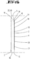
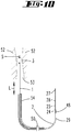
- a guide wire 12 was first passed through the working channel of a first endoscope 51 with a comparatively thick cross-section in the distal direction until the distal longitudinal end of the guide wire 50 is at a desired position in a cavity 53 in a human or human body, indicated schematically by boundary walls 52 animal body is located.
- the balloon catheter 1 with an unpressurized, ie slim, balloon 3 was guided along the advanced guide wire 50 through the working channel of the thick endoscope 51 until the balloon 3 is in a desired position in the cavity 53.
- the guide wire 12 can be passed through the second channel 16 of the catheter line 2.
- the fluid located on the syringe 10 (in the example air) was passed through the first channel 15 in the manner described above into the balloon 3, whereby this, as Figure 8 shows, expands elastically and thus braced between the boundary walls 52.
- the balloon 3 anchors the balloon catheter 1 in the area of its distal longitudinal end 5, so that an unintentional displacement of the balloon catheter 1, in particular in its longitudinal direction L, is effectively prevented.
- the grip piece 35 was pushed forward into its distal end position and secured there on the connecting device 6 by means of a thread.
- Figure 9 shows that the cross-sectional dimensions of the connection device 6 are larger than the cross-section of the working channel in the endoscope 51, so that the endoscope 51 cannot be withdrawn in the proximal direction over the connection device 6.
- the possibility of severing the balloon catheter 1 at its marking 47 for example.
- the length section of the anti-kink sleeve 46 distally adjoining the marking 47 only loosely surrounds the catheter line 2, so that this length section can be moved freely along the catheter line 2.
- this movable section of the anti-kink sleeve 46 has already been removed.
- the transition 28 is still located in the length section of the catheter line 2 connected to the balloon 3, and the valve elements 24, 25 are still located in the second channel length section 29. This has the effect that the balloon 3 remains inflated and maintains its anchoring effect .
- the balloon 3 in the exemplary use shown in the figures until the valve elements 24, 25, i. H. as long as the balloon 3 is inflated and thereby expanded, remains clamped between the boundary walls 52 and consequently remains unchanged in the desired position in the cavity 53 even during the endoscope exchange.
- the balloon catheter 1 does not shift in the longitudinal direction L during the exchange of the endoscopes 51, 54. Only a contraction of the balloon 3 eliminates this holding effect, so that the position fixation is canceled and the balloon 3 can be withdrawn from between the boundary walls 52 and through the endoscope 54 that was last used. It goes without saying, however, that there are also other possible uses.
- the balloon catheter according to the invention in its as yet uncut initial state enables the force transmission device 11 (the valve slide) to be pushed back and forth several times if necessary in order to interact with the filling device 56 (syringe 10) several times depending on the desired application to expand and contract.
- the openings 50 in the figures do not represent actual separation points, but are only used symbolically for the shortened representation of the catheter line 2, the length of which can be significantly greater than shown.
- the balloon 3 can be filled with air again even after the valve elements 24, 25 have been separated and can thus be expanded.
- a refilling of the balloon 3 can take place again directly at a position between the boundary walls 52 of the body cavity 53.
- a suitable filling device 56 which is preferred with regard to this Function can also be referred to as a refilling device, is initially with reference to the Figures 12-14 described, the representation there being enlarged compared to the preceding and following figures.
- the filling device 56 comprises a hollow needle 57 and a housing 58 adjoining it in a sealing manner, which in the example consists of plastic.
- connection 59 which is the detachable connection of a syringe 10 (cf. Figure 14 ) allows.
- a hollow fluid passage 60 extends in the interior of the housing 58 and is in fluidic connection distally with the hollow needle 57 and proximally with the connector 59.
- a shut-off valve 61 is inserted, the valve body of which can optionally be rotated by means of a rotary handle 62 into a rotary position in which a passage opening in the valve body provides a connection through which fluid (preferably air) can flow between the two Sections of the fluid passage 60 located on the sides of the shut-off valve 61 (that is to say therefrom and behind), or in another rotational position in which the valve body separates these two sections from one another in a sealing manner.
- the fluid passage 60 can thus be opened by means of the shut-off valve 61 either to allow fluid to pass from the syringe 10 or to be closed to prevent the passage of fluid.
- the shut-off valve 61 could, however, be dispensed with in the example if the syringe 10 can be connected to the housing 58 in a sealing manner and the syringe plunger is also sealed in the syringe housing.
- the outside diameter of the hollow needle 57 is only a few hundredths of a millimeter, that is to say only slightly, larger than the inside diameter of the first channel 15 of the elastic catheter line 2.
- a mandrin 63 is passed through the filling device 56. It comprises a wire section 64 and a proximal handle section 65.
- the wire section 64 extends through the connection 59, the fluid passage 60, the open shut-off valve 61 and the hollow needle 57 and its distal longitudinal end 66 projects over the tip the hollow needle 57 emerges.
- the mandrin 63 is removed from the filling device 56 and a syringe 10 is connected to the connection 59 in a sealing manner.
- the Figures 15 , 16 show by way of example how, based on the state of use of the balloon catheter 1 according to FIG Figure 11 the filling device 56 can be used to refill or expand the balloon 3.
- Figure 15 the proximal longitudinal end 67 of a length section 68 of the catheter line 2 which is still firmly connected to the balloon 3 and which was formed in the area of the marking 48 during separation.
- Figure 15 shows that the filling device 56 with the mandrin 63 inserted therein is inserted in the direction of movement of the arrow 69 at the proximal longitudinal end 67 into the first channel 15.
- the wire section 64 the diameter of which is smaller than the outer diameter of the hollow needle 57, serves as a threading aid.
- Figure 16 shows a state of use in which the air has already been pumped from the syringe 10 by means of the filling device 56 into the first channel 15 of the catheter line 2 and through the first channel 15 into the balloon 3, which has thus been refilled and expanded so that a desired clamping effect or position fixation between the boundary walls 52 of the body cavity 53 can be achieved again.
- the shut-off valve 61 can be turned into its closed position. Around To be able to deflate or contract the balloon again so that it can be removed from the cavity 53, there is the possibility that the hollow needle 57 is pulled proximally from the catheter line 2 or that the shut-off valve is opened.
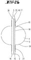
- the balloon 3 is in the Figures 1b and 2 B in the manner shown in section, attached to or formed on the catheter line 2, ie the catheter line 2 extends through the interior of the balloon 3.
- the section of the catheter line 2 passing through the balloon 3 is not shown for the sake of clarity, although the balloon envelope can also consist, for example, of a translucent material.
Landscapes
- Health & Medical Sciences (AREA)
- Life Sciences & Earth Sciences (AREA)
- Heart & Thoracic Surgery (AREA)
- Animal Behavior & Ethology (AREA)
- Anesthesiology (AREA)
- Biomedical Technology (AREA)
- Hematology (AREA)
- Engineering & Computer Science (AREA)
- Pulmonology (AREA)
- General Health & Medical Sciences (AREA)
- Public Health (AREA)
- Veterinary Medicine (AREA)
- Biophysics (AREA)
- Child & Adolescent Psychology (AREA)
- Media Introduction/Drainage Providing Device (AREA)
- Infusion, Injection, And Reservoir Apparatuses (AREA)
Claims (17)
- Cathéter à ballonnet (1), comprenant une conduite de cathéter (2), un ballonnet (3) expansible fixé à celle-ci, qui délimite un espace intérieur de ballonnet (4), et un dispositif de raccordement (6) lié à la conduite de cathéter (2), qui présente au moins un premier raccord (7) pour l'alimentation en fluide, en particulier en air, pour le remplissage du ballonnet (3), dans lequel au moins un premier canal (15) s'étend dans la conduite de cathéter (2), qui est en liaison de fluide avec le premier raccord (7) à son extrémité longitudinale proximale (17) et qui est en liaison de fluide avec l'intérieur du ballonnet (4) à son extrémité longitudinale distale (26), dans lequel le premier canal (15) présente un premier tronçon longitudinal de canal (27) et un deuxième tronçon longitudinal de canal (29) qui s'y raccorde dans la direction distale avec une transition (28), dans lequel la conduite de cathéter (2) est réalisée en matériau élastique au moins le long de ces tronçons longitudinaux de canal (27, 29) et le long de la transition (28), dans lequel le cathéter à ballonnet (1) présente au moins un premier élément de valve (24), en particulier conçu sous forme de bille, qui est inséré dans le premier canal (15), dans lequel, en particulier lorsque la paroi de la conduite de cathéter (2) est respectivement détendue, la surface de la section transversale creuse du premier canal (15) dans le deuxième tronçon longitudinal de canal (29) est plus petite que la surface de la section transversale creuse du premier canal (15) dans le premier tronçon longitudinal de canal (27) et plus petite que la surface de la section transversale du premier élément de valve (24) orientée perpendiculairement à la direction longitudinale (L) de la conduite de cathéter (2), et dans lequel le cathéter à ballonnet (1) présente un dispositif de transmission de force (11), caractérisé en ce que le dispositif de transmission de force (11) est fixé au premier élément de valve (24) et s'étend depuis le premier élément de valve (24) en direction proximale à travers le premier canal (15) et après à travers les moyens de raccordement (6) jusqu'à une poignée (35), dans lequel le premier élément de valve (24) peut, au moyen d'un mouvement de la poignée (35) par rapport au dispositif de raccordement (6), être déplacé du premier tronçon longitudinal de canal (27) dans le deuxième tronçon longitudinal de canal (29) avec une expansion élastique de la paroi (30) de la conduite de cathéter (2) à son endroit.
- Cathéter à ballonnet (1) selon la revendication 1, caractérisé en ce que la surface de la section transversale creuse du premier canal (15) à chaque endroit dans le deuxième tronçon longitudinal de canal (29) est plus petite que la surface de la section transversale creuse du premier canal (15) à chaque endroit dans le premier tronçon longitudinal de canal (27) et plus petite que la surface de la plus grande section transversale du premier élément de valve (24) orientée perpendiculairement à la direction longitudinale (L) de la conduite de cathéter (2).
- Cathéter à ballonnet (1) selon une ou plusieurs des revendications précédentes, caractérisé en ce que, en particulier avec la paroi (30) de la conduite de cathéter (2) respectivement détendue, la section transversale creuse du premier canal (15) dans le premier tronçon longitudinal de canal (27) est uniforme ou sensiblement uniforme, où sensiblement uniforme signifie que toute différence de taille se situe uniquement dans une fourchette de pourcentage à un chiffre, et la section creuse du premier canal (15) dans le deuxième tronçon longitudinal de canal (29) qui s'en écarte en termes de surface est également uniforme ou sensiblement uniforme dans celui-ci, où sensiblement uniforme signifie que toute différence de taille se situe uniquement dans une fourchette de pourcentage à un chiffre.
- Cathéter à ballonnet (1) selon la revendication 1, caractérisé en ce que, en particulier lorsque la paroi (30) de la ligne de cathéter (2) est détendue, la surface de la section transversale creuse du premier canal (15) dans le premier tronçon longitudinal de canal (27) est supérieure ou égale ou inférieure à la surface de la section transversale du premier élément de soupape (24).
- Cathéter à ballonnet (1) selon une ou plusieurs des revendications précédentes, caractérisé en ce que, en particulier lorsque la paroi (30) de la conduite de cathéter (2) est respectivement détendue, le premier canal (15) présente une section transversale creuse circulaire dans le premier tronçon longitudinal de canal (27) avec un premier diamètre de canal uniforme (dk1) dans le premier tronçon longitudinal de canal (27) et une section transversale creuse circulaire dans le deuxième tronçon longitudinal de canal (29) avec un deuxième diamètre de canal uniforme (dk2) dans le deuxième tronçon longitudinal de canal (29), dans lequel le deuxième diamètre de canal (dk2) est plus petit que le premier diamètre de canal (dk1) et plus petit que le diamètre du premier élément de valve (24) qui est formé comme une sphère ou un hémisphère.
- Cathéter à ballonnet (1) selon une ou plusieurs des revendications précédentes, caractérisé en ce que, en particulier avec la paroi (30) de la conduite de cathéter (2) respectivement détendue, dans le premier tronçon longitudinal de canal (27), le diamètre du premier canal (dk1) est supérieur ou égal ou inférieur au diamètre (dv1) du premier élément de soupape (24) conçu comme une bille ou une demi-bille.
- Cathéter à ballonnet (1) selon une ou plusieurs des revendications précédentes, caractérisé en ce que dans le premier canal (15), dans la transition (28) entre le premier tronçon longitudinal de canal (27) et le deuxième tronçon longitudinal de canal (29), la section transversale creuse du premier canal (15) se rétrécit de manière continue, en particulier de manière conique, dans la direction distale.
- Cathéter à ballonnet (1) selon une ou plusieurs des revendications précédentes, caractérisé en ce qu'une première butée (38) est fixée ou formée sur le dispositif de transmission de force (11) et qu'une première contre-butée (39) est fixée ou formée sur le dispositif de raccordement (6) et que la poignée (35) peut être avancée vers le dispositif de raccordement (6) jusqu'à une position d'extrémité distale où, en atteignant celle-ci, la première butée (38) vient buter contre la première contre-butée (39) de manière à limiter le déplacement par complémentarité de forme et le premier élément de valve (24) est situé dans le deuxième tronçon longitudinal de canal (29).
- Cathéter à ballonnet (1) selon une ou plusieurs des revendications précédentes, caractérisé en ce qu'une deuxième butée (43) est fixée ou formée sur le dispositif de transmission de force (11) et une deuxième contre-butée (44) est fixée ou formée sur le dispositif de raccordement (6), et en ce que la poignée (35) peut être retirée du dispositif de raccordement (6) jusqu'à une position finale proximale où, en atteignant celle-ci, la deuxième butée (43)vient buter contre la deuxième contre-butée (44) de manière à limiter le mouvement de traction par complémentarité de forme et le premier élément de valve (24) se trouve dans le premier tronçon longitudinal du canal (27).
- Cathéter à ballonnet (1) selon une ou plusieurs des revendications précédentes, caractérisé en ce que le cathéter à ballonnet (1) présente un deuxième élément de valve (25), en particulier de forme cylindrique, contigu au premier élément de soupape (24) sur son côté proximal, dans lequel, en particulier, il est prévu que le diamètre (dv2) du deuxième élément de valve (25) correspond au diamètre (dv1) du premier élément de valve (24), dans lequel, lorsque la poignée (35) est en position d'extrémité distale, le deuxième élément de valve (25) est situé entièrement ou partiellement dans le deuxième tronçon longitudinal de canal (29) du premier canal (15).
- Cathéter à ballonnet (1) selon une ou plusieurs des revendications précédentes, caractérisé en ce que l'extrémité longitudinale proximale du deuxième tronçon longitudinal de canal (29) est espacée en direction distale du dispositif de raccordement (6).
- Cathéter à ballonnet (1) selon une ou plusieurs des revendications précédentes, caractérisé en ce que la surface extérieure de la conduite de cathéter (2) est en plastique tel que du PTFE ou en caoutchouc au moins le long des premier et deuxième tronçons longitudinaux de canal (27, 29) et de la transition (28).
- Cathéter à ballonnet (1) selon une ou plusieurs des revendications précédentes, caractérisé en ce que la conduite de cathéter (2) est formée en une seule pièce au moins dans une partie longitudinale comprenant le premier tronçon longitudinal de canal (27), la transition (28) et le deuxième tronçon longitudinal de canal (29).
- Cathéter à ballonnet (1) selon une ou plusieurs des revendications précédentes, caractérisé en ce que le cathéter à ballonnet (1) présente un manchon anti-pliage (46) qui est fixé au dispositif de raccordement (6) et qui, à partir de là, entoure de manière lâche une partie longitudinale de la conduite de cathéter qui s'étend du dispositif de raccordement (6) dans la direction distale jusqu'au deuxième tronçon longitudinal de canal (29), et qu'un premier marquage (47) visible de l'extérieur, en particulier un anneau d'une première couleur, est apposé sur le manchon anti-pliage (46), le premier marquage (47) étant espacé de l'extrémité longitudinale distale du premier tronçon longitudinal de canal (27) dans la direction proximale.
- Cathéter à ballonnet (1) selon une ou plusieurs des revendications précédentes, caractérisé en ce qu'un deuxième marquage (48), en particulier un anneau d'une deuxième couleur, est apposé sur la conduite de cathéter (2), lequel marquage est visible de l'extérieur lorsque la conduite de cathéter (2) est exposée, dans lequel le deuxième marquage (48) est espacé dans la direction distale de l'extrémité longitudinale proximale du deuxième tronçon longitudinal de canal (29) et du premier élément de valve (24), même lorsque la poignée (35) est dans sa position d'extrémité distale, et qui est agencé en particulier sur la partie longitudinale de la conduite de cathéter (2) entourée de manière lâche par le manchon anti-pliage (46).
- Cathéter à ballonnet (1) selon une ou plusieurs des revendications précédentes, caractérisé en ce qu'il est prévu un dispositif de remplissage (56) qui comprend une aiguille creuse (57) et un boîtier (58) se raccordant à celle-ci, dans lequel est prévu sur le dispositif de remplissage (56) au moins un raccord (6) pour l'alimentation en fluide pour le remplissage du ballonnet (3), en particulier un raccord (59) pour la fixation amovible d'une seringue (10), en ce que le raccord (59) et l'aiguille creuse (57) sont en liaison de fluide l'un avec l'autre au moyen d'un passage de fluide (60) s'étendant dans le boîtier (58) et en ce que la section transversale extérieure de l'aiguille creuse (57) est légèrement plus grande que la section transversale creuse du premier canal (15) dans le deuxième tronçon longitudinal de canal (29).
- Cathéter à ballonnet (1) selon une ou plusieurs des revendications précédentes, caractérisé en ce que le dispositif de raccordement (6) comporte un troisième raccord (9) et en ce que la conduite de cathéter (2) comporte un deuxième canal (16) reliant le troisième raccord (9) à une ouverture (49) de la conduite de cathéter (2) à son extrémité distale (5).
Applications Claiming Priority (1)
| Application Number | Priority Date | Filing Date | Title |
|---|---|---|---|
| DE102015101613.3A DE102015101613A1 (de) | 2015-02-04 | 2015-02-04 | Ballonkatheter |
Publications (3)
| Publication Number | Publication Date |
|---|---|
| EP3056239A2 EP3056239A2 (fr) | 2016-08-17 |
| EP3056239A3 EP3056239A3 (fr) | 2016-10-19 |
| EP3056239B1 true EP3056239B1 (fr) | 2020-10-28 |
Family
ID=55299358
Family Applications (1)
| Application Number | Title | Priority Date | Filing Date |
|---|---|---|---|
| EP16154040.6A Active EP3056239B1 (fr) | 2015-02-04 | 2016-02-03 | Cathéter à ballonnet |
Country Status (2)
| Country | Link |
|---|---|
| EP (1) | EP3056239B1 (fr) |
| DE (1) | DE102015101613A1 (fr) |
Families Citing this family (2)
| Publication number | Priority date | Publication date | Assignee | Title |
|---|---|---|---|---|
| CN113172653B (zh) * | 2021-05-22 | 2023-06-13 | 苏州科技大学 | 柔性夹爪及自动化设备 |
| CN115920211A (zh) * | 2022-12-12 | 2023-04-07 | 浙江巴泰医疗科技有限公司 | 一种尖端结构、包含有该尖端结构的球囊扩张导管及制备方法 |
Family Cites Families (4)
| Publication number | Priority date | Publication date | Assignee | Title |
|---|---|---|---|---|
| US3982544A (en) * | 1974-11-18 | 1976-09-28 | Johnson & Johnson | Device for everting a probe into a body cavity |
| US8568354B2 (en) * | 2010-02-16 | 2013-10-29 | Cardiovascular Systems, Inc. | Devices and methods for low shearing local delivery of therapeutic agents to the wall of a bodily lumen |
| DE102012109894A1 (de) * | 2012-04-10 | 2013-10-10 | Mtw - Endoskopie W. Haag Kg | Ballonkatheter und Verfahren zu dessen Verwendung |
| DE102013110989A1 (de) | 2013-10-02 | 2015-04-02 | Mtw - Endoskopie W. Haag Kg | Ballonkatheter |
-
2015
- 2015-02-04 DE DE102015101613.3A patent/DE102015101613A1/de not_active Withdrawn
-
2016
- 2016-02-03 EP EP16154040.6A patent/EP3056239B1/fr active Active
Non-Patent Citations (1)
| Title |
|---|
| None * |
Also Published As
| Publication number | Publication date |
|---|---|
| EP3056239A2 (fr) | 2016-08-17 |
| EP3056239A3 (fr) | 2016-10-19 |
| DE102015101613A1 (de) | 2016-08-04 |
Similar Documents
| Publication | Publication Date | Title |
|---|---|---|
| EP1893272B1 (fr) | Auxiliaire d'introduction destiné à une trachéostomie percutanée | |
| DE69613897T2 (de) | Ballonkatheter mit Ballonschutzumhüllung | |
| DE3303867A1 (de) | Katheter | |
| DE2804058B2 (de) | Medizinisches Gerät zur Entfernung von Fremdkörpern aus einem Körperhohlraum | |
| DE112012005410T5 (de) | Schleuseneinrichtung zum Einführen eines Katheters | |
| EP2296561A1 (fr) | Bouchon pour endoscope | |
| DE3028089A1 (de) | Vorrichtung zum dilatieren eines blutgefaessverschlusses | |
| EP2316351A2 (fr) | Instrument médical destiné à installer des pinces pour tissu | |
| EP0853953A1 (fr) | Set de ponction | |
| EP1294322A1 (fr) | Dispositif pour injecter du ciment osseux | |
| EP2316350A1 (fr) | Dispositif de résection | |
| EP1559379A1 (fr) | Dispositif d'implantation de marqueurs | |
| DE112005001566T5 (de) | Einführungseinrichtung für endoluminale Eingriffe | |
| DE1957647A1 (de) | Passstueck zum Anschliessen eines Katheterschlauchs an eine Armatur od.dgl. und Verfahren zum Befestigen des Passstueckes an einem Katheterschlauch | |
| EP3056239B1 (fr) | Cathéter à ballonnet | |
| WO2015049132A1 (fr) | Cathéter à ballonnet | |
| DE20110921U1 (de) | Uterus Manipulator | |
| DE202007000173U1 (de) | Punktionseinheit mit einem Drainagekatheter | |
| WO2013153050A2 (fr) | Cathéter à ballonnet et son procédé d'utilisation | |
| EP3012033A1 (fr) | Pistolet de colle chaude | |
| DE102009032186A1 (de) | Vorrichtung zum Einführen eines Mediums oder eines Instruments in den menschlichen Körper | |
| EP2455018B1 (fr) | Gaine de trocart pour l'introduction dans une incision de peau | |
| EP1979033B1 (fr) | Systeme de catheter | |
| DE102013101338A1 (de) | Ballonkatheter und Verfahren zum Spülen eines Ballonkatheters | |
| DE2537793C2 (de) | Blindnietgerät |
Legal Events
| Date | Code | Title | Description |
|---|---|---|---|
| PUAI | Public reference made under article 153(3) epc to a published international application that has entered the european phase |
Free format text: ORIGINAL CODE: 0009012 |
|
| AK | Designated contracting states |
Kind code of ref document: A2 Designated state(s): AL AT BE BG CH CY CZ DE DK EE ES FI FR GB GR HR HU IE IS IT LI LT LU LV MC MK MT NL NO PL PT RO RS SE SI SK SM TR |
|
| AX | Request for extension of the european patent |
Extension state: BA ME |
|
| PUAL | Search report despatched |
Free format text: ORIGINAL CODE: 0009013 |
|
| AK | Designated contracting states |
Kind code of ref document: A3 Designated state(s): AL AT BE BG CH CY CZ DE DK EE ES FI FR GB GR HR HU IE IS IT LI LT LU LV MC MK MT NL NO PL PT RO RS SE SI SK SM TR |
|
| AX | Request for extension of the european patent |
Extension state: BA ME |
|
| RIC1 | Information provided on ipc code assigned before grant |
Ipc: A61M 25/01 20060101ALN20160912BHEP Ipc: A61M 39/24 20060101ALI20160912BHEP Ipc: A61M 25/00 20060101AFI20160912BHEP Ipc: A61M 25/10 20060101ALI20160912BHEP |
|
| STAA | Information on the status of an ep patent application or granted ep patent |
Free format text: STATUS: REQUEST FOR EXAMINATION WAS MADE |
|
| 17P | Request for examination filed |
Effective date: 20170329 |
|
| RBV | Designated contracting states (corrected) |
Designated state(s): AL AT BE BG CH CY CZ DE DK EE ES FI FR GB GR HR HU IE IS IT LI LT LU LV MC MK MT NL NO PL PT RO RS SE SI SK SM TR |
|
| GRAP | Despatch of communication of intention to grant a patent |
Free format text: ORIGINAL CODE: EPIDOSNIGR1 |
|
| STAA | Information on the status of an ep patent application or granted ep patent |
Free format text: STATUS: GRANT OF PATENT IS INTENDED |
|
| INTG | Intention to grant announced |
Effective date: 20200507 |
|
| GRAS | Grant fee paid |
Free format text: ORIGINAL CODE: EPIDOSNIGR3 |
|
| GRAA | (expected) grant |
Free format text: ORIGINAL CODE: 0009210 |
|
| STAA | Information on the status of an ep patent application or granted ep patent |
Free format text: STATUS: THE PATENT HAS BEEN GRANTED |
|
| AK | Designated contracting states |
Kind code of ref document: B1 Designated state(s): AL AT BE BG CH CY CZ DE DK EE ES FI FR GB GR HR HU IE IS IT LI LT LU LV MC MK MT NL NO PL PT RO RS SE SI SK SM TR |
|
| REG | Reference to a national code |
Ref country code: GB Ref legal event code: FG4D Free format text: NOT ENGLISH |
|
| REG | Reference to a national code |
Ref country code: CH Ref legal event code: NV Representative=s name: R.A. EGLI AND CO, PATENTANWAELTE, CH Ref country code: CH Ref legal event code: EP |
|
| REG | Reference to a national code |
Ref country code: AT Ref legal event code: REF Ref document number: 1327590 Country of ref document: AT Kind code of ref document: T Effective date: 20201115 |
|
| REG | Reference to a national code |
Ref country code: DE Ref legal event code: R096 Ref document number: 502016011526 Country of ref document: DE |
|
| REG | Reference to a national code |
Ref country code: IE Ref legal event code: FG4D Free format text: LANGUAGE OF EP DOCUMENT: GERMAN |
|
| REG | Reference to a national code |
Ref country code: NL Ref legal event code: MP Effective date: 20201028 |
|
| PG25 | Lapsed in a contracting state [announced via postgrant information from national office to epo] |
Ref country code: PT Free format text: LAPSE BECAUSE OF FAILURE TO SUBMIT A TRANSLATION OF THE DESCRIPTION OR TO PAY THE FEE WITHIN THE PRESCRIBED TIME-LIMIT Effective date: 20210301 Ref country code: RS Free format text: LAPSE BECAUSE OF FAILURE TO SUBMIT A TRANSLATION OF THE DESCRIPTION OR TO PAY THE FEE WITHIN THE PRESCRIBED TIME-LIMIT Effective date: 20201028 Ref country code: FI Free format text: LAPSE BECAUSE OF FAILURE TO SUBMIT A TRANSLATION OF THE DESCRIPTION OR TO PAY THE FEE WITHIN THE PRESCRIBED TIME-LIMIT Effective date: 20201028 Ref country code: NL Free format text: LAPSE BECAUSE OF FAILURE TO SUBMIT A TRANSLATION OF THE DESCRIPTION OR TO PAY THE FEE WITHIN THE PRESCRIBED TIME-LIMIT Effective date: 20201028 Ref country code: NO Free format text: LAPSE BECAUSE OF FAILURE TO SUBMIT A TRANSLATION OF THE DESCRIPTION OR TO PAY THE FEE WITHIN THE PRESCRIBED TIME-LIMIT Effective date: 20210128 Ref country code: GR Free format text: LAPSE BECAUSE OF FAILURE TO SUBMIT A TRANSLATION OF THE DESCRIPTION OR TO PAY THE FEE WITHIN THE PRESCRIBED TIME-LIMIT Effective date: 20210129 |
|
| PGFP | Annual fee paid to national office [announced via postgrant information from national office to epo] |
Ref country code: CH Payment date: 20210215 Year of fee payment: 6 |
|
| REG | Reference to a national code |
Ref country code: LT Ref legal event code: MG4D |
|
| PG25 | Lapsed in a contracting state [announced via postgrant information from national office to epo] |
Ref country code: BG Free format text: LAPSE BECAUSE OF FAILURE TO SUBMIT A TRANSLATION OF THE DESCRIPTION OR TO PAY THE FEE WITHIN THE PRESCRIBED TIME-LIMIT Effective date: 20210128 Ref country code: SE Free format text: LAPSE BECAUSE OF FAILURE TO SUBMIT A TRANSLATION OF THE DESCRIPTION OR TO PAY THE FEE WITHIN THE PRESCRIBED TIME-LIMIT Effective date: 20201028 Ref country code: LV Free format text: LAPSE BECAUSE OF FAILURE TO SUBMIT A TRANSLATION OF THE DESCRIPTION OR TO PAY THE FEE WITHIN THE PRESCRIBED TIME-LIMIT Effective date: 20201028 Ref country code: PL Free format text: LAPSE BECAUSE OF FAILURE TO SUBMIT A TRANSLATION OF THE DESCRIPTION OR TO PAY THE FEE WITHIN THE PRESCRIBED TIME-LIMIT Effective date: 20201028 Ref country code: IS Free format text: LAPSE BECAUSE OF FAILURE TO SUBMIT A TRANSLATION OF THE DESCRIPTION OR TO PAY THE FEE WITHIN THE PRESCRIBED TIME-LIMIT Effective date: 20210228 Ref country code: ES Free format text: LAPSE BECAUSE OF FAILURE TO SUBMIT A TRANSLATION OF THE DESCRIPTION OR TO PAY THE FEE WITHIN THE PRESCRIBED TIME-LIMIT Effective date: 20201028 |
|
| PGFP | Annual fee paid to national office [announced via postgrant information from national office to epo] |
Ref country code: AT Payment date: 20210212 Year of fee payment: 6 Ref country code: DE Payment date: 20201218 Year of fee payment: 6 |
|
| PG25 | Lapsed in a contracting state [announced via postgrant information from national office to epo] |
Ref country code: HR Free format text: LAPSE BECAUSE OF FAILURE TO SUBMIT A TRANSLATION OF THE DESCRIPTION OR TO PAY THE FEE WITHIN THE PRESCRIBED TIME-LIMIT Effective date: 20201028 |
|
| REG | Reference to a national code |
Ref country code: DE Ref legal event code: R097 Ref document number: 502016011526 Country of ref document: DE |
|
| PG25 | Lapsed in a contracting state [announced via postgrant information from national office to epo] |
Ref country code: SK Free format text: LAPSE BECAUSE OF FAILURE TO SUBMIT A TRANSLATION OF THE DESCRIPTION OR TO PAY THE FEE WITHIN THE PRESCRIBED TIME-LIMIT Effective date: 20201028 Ref country code: RO Free format text: LAPSE BECAUSE OF FAILURE TO SUBMIT A TRANSLATION OF THE DESCRIPTION OR TO PAY THE FEE WITHIN THE PRESCRIBED TIME-LIMIT Effective date: 20201028 Ref country code: EE Free format text: LAPSE BECAUSE OF FAILURE TO SUBMIT A TRANSLATION OF THE DESCRIPTION OR TO PAY THE FEE WITHIN THE PRESCRIBED TIME-LIMIT Effective date: 20201028 Ref country code: CZ Free format text: LAPSE BECAUSE OF FAILURE TO SUBMIT A TRANSLATION OF THE DESCRIPTION OR TO PAY THE FEE WITHIN THE PRESCRIBED TIME-LIMIT Effective date: 20201028 Ref country code: SM Free format text: LAPSE BECAUSE OF FAILURE TO SUBMIT A TRANSLATION OF THE DESCRIPTION OR TO PAY THE FEE WITHIN THE PRESCRIBED TIME-LIMIT Effective date: 20201028 Ref country code: LT Free format text: LAPSE BECAUSE OF FAILURE TO SUBMIT A TRANSLATION OF THE DESCRIPTION OR TO PAY THE FEE WITHIN THE PRESCRIBED TIME-LIMIT Effective date: 20201028 |
|
| PG25 | Lapsed in a contracting state [announced via postgrant information from national office to epo] |
Ref country code: DK Free format text: LAPSE BECAUSE OF FAILURE TO SUBMIT A TRANSLATION OF THE DESCRIPTION OR TO PAY THE FEE WITHIN THE PRESCRIBED TIME-LIMIT Effective date: 20201028 |
|
| PLBE | No opposition filed within time limit |
Free format text: ORIGINAL CODE: 0009261 |
|
| STAA | Information on the status of an ep patent application or granted ep patent |
Free format text: STATUS: NO OPPOSITION FILED WITHIN TIME LIMIT |
|
| PG25 | Lapsed in a contracting state [announced via postgrant information from national office to epo] |
Ref country code: MC Free format text: LAPSE BECAUSE OF FAILURE TO SUBMIT A TRANSLATION OF THE DESCRIPTION OR TO PAY THE FEE WITHIN THE PRESCRIBED TIME-LIMIT Effective date: 20201028 |
|
| 26N | No opposition filed |
Effective date: 20210729 |
|
| GBPC | Gb: european patent ceased through non-payment of renewal fee |
Effective date: 20210203 |
|
| REG | Reference to a national code |
Ref country code: BE Ref legal event code: MM Effective date: 20210228 |
|
| PG25 | Lapsed in a contracting state [announced via postgrant information from national office to epo] |
Ref country code: IT Free format text: LAPSE BECAUSE OF FAILURE TO SUBMIT A TRANSLATION OF THE DESCRIPTION OR TO PAY THE FEE WITHIN THE PRESCRIBED TIME-LIMIT Effective date: 20201028 Ref country code: AL Free format text: LAPSE BECAUSE OF FAILURE TO SUBMIT A TRANSLATION OF THE DESCRIPTION OR TO PAY THE FEE WITHIN THE PRESCRIBED TIME-LIMIT Effective date: 20201028 Ref country code: LU Free format text: LAPSE BECAUSE OF NON-PAYMENT OF DUE FEES Effective date: 20210203 |
|
| PG25 | Lapsed in a contracting state [announced via postgrant information from national office to epo] |
Ref country code: SI Free format text: LAPSE BECAUSE OF FAILURE TO SUBMIT A TRANSLATION OF THE DESCRIPTION OR TO PAY THE FEE WITHIN THE PRESCRIBED TIME-LIMIT Effective date: 20201028 |
|
| PG25 | Lapsed in a contracting state [announced via postgrant information from national office to epo] |
Ref country code: IE Free format text: LAPSE BECAUSE OF NON-PAYMENT OF DUE FEES Effective date: 20210203 Ref country code: GB Free format text: LAPSE BECAUSE OF NON-PAYMENT OF DUE FEES Effective date: 20210203 Ref country code: FR Free format text: LAPSE BECAUSE OF NON-PAYMENT OF DUE FEES Effective date: 20210228 |
|
| PG25 | Lapsed in a contracting state [announced via postgrant information from national office to epo] |
Ref country code: IS Free format text: LAPSE BECAUSE OF FAILURE TO SUBMIT A TRANSLATION OF THE DESCRIPTION OR TO PAY THE FEE WITHIN THE PRESCRIBED TIME-LIMIT Effective date: 20210228 |
|
| PG25 | Lapsed in a contracting state [announced via postgrant information from national office to epo] |
Ref country code: BE Free format text: LAPSE BECAUSE OF NON-PAYMENT OF DUE FEES Effective date: 20210228 |
|
| REG | Reference to a national code |
Ref country code: DE Ref legal event code: R119 Ref document number: 502016011526 Country of ref document: DE |
|
| REG | Reference to a national code |
Ref country code: CH Ref legal event code: PL |
|
| REG | Reference to a national code |
Ref country code: AT Ref legal event code: MM01 Ref document number: 1327590 Country of ref document: AT Kind code of ref document: T Effective date: 20220203 |
|
| PG25 | Lapsed in a contracting state [announced via postgrant information from national office to epo] |
Ref country code: AT Free format text: LAPSE BECAUSE OF NON-PAYMENT OF DUE FEES Effective date: 20220203 |
|
| PG25 | Lapsed in a contracting state [announced via postgrant information from national office to epo] |
Ref country code: LI Free format text: LAPSE BECAUSE OF NON-PAYMENT OF DUE FEES Effective date: 20220228 Ref country code: DE Free format text: LAPSE BECAUSE OF NON-PAYMENT OF DUE FEES Effective date: 20220901 Ref country code: CH Free format text: LAPSE BECAUSE OF NON-PAYMENT OF DUE FEES Effective date: 20220228 |
|
| PG25 | Lapsed in a contracting state [announced via postgrant information from national office to epo] |
Ref country code: HU Free format text: LAPSE BECAUSE OF FAILURE TO SUBMIT A TRANSLATION OF THE DESCRIPTION OR TO PAY THE FEE WITHIN THE PRESCRIBED TIME-LIMIT; INVALID AB INITIO Effective date: 20160203 |
|
| PG25 | Lapsed in a contracting state [announced via postgrant information from national office to epo] |
Ref country code: CY Free format text: LAPSE BECAUSE OF FAILURE TO SUBMIT A TRANSLATION OF THE DESCRIPTION OR TO PAY THE FEE WITHIN THE PRESCRIBED TIME-LIMIT Effective date: 20201028 |
|
| PG25 | Lapsed in a contracting state [announced via postgrant information from national office to epo] |
Ref country code: MK Free format text: LAPSE BECAUSE OF FAILURE TO SUBMIT A TRANSLATION OF THE DESCRIPTION OR TO PAY THE FEE WITHIN THE PRESCRIBED TIME-LIMIT Effective date: 20201028 |
|
| PG25 | Lapsed in a contracting state [announced via postgrant information from national office to epo] |
Ref country code: TR Free format text: LAPSE BECAUSE OF FAILURE TO SUBMIT A TRANSLATION OF THE DESCRIPTION OR TO PAY THE FEE WITHIN THE PRESCRIBED TIME-LIMIT Effective date: 20201028 |