EP3056163B2 - Visualisierungssytem - Google Patents
Visualisierungssytem Download PDFInfo
- Publication number
- EP3056163B2 EP3056163B2 EP16153458.1A EP16153458A EP3056163B2 EP 3056163 B2 EP3056163 B2 EP 3056163B2 EP 16153458 A EP16153458 A EP 16153458A EP 3056163 B2 EP3056163 B2 EP 3056163B2
- Authority
- EP
- European Patent Office
- Prior art keywords
- endoscope
- operating
- microscope
- wavelength range
- operating state
- Prior art date
- Legal status (The legal status is an assumption and is not a legal conclusion. Google has not performed a legal analysis and makes no representation as to the accuracy of the status listed.)
- Active
Links
Images


Classifications
-
- A—HUMAN NECESSITIES
- A61—MEDICAL OR VETERINARY SCIENCE; HYGIENE
- A61B—DIAGNOSIS; SURGERY; IDENTIFICATION
- A61B1/00—Instruments for performing medical examinations of the interior of cavities or tubes of the body by visual or photographical inspection, e.g. endoscopes; Illuminating arrangements therefor
- A61B1/00002—Operational features of endoscopes
- A61B1/00011—Operational features of endoscopes characterised by signal transmission
-
- A—HUMAN NECESSITIES
- A61—MEDICAL OR VETERINARY SCIENCE; HYGIENE
- A61B—DIAGNOSIS; SURGERY; IDENTIFICATION
- A61B1/00—Instruments for performing medical examinations of the interior of cavities or tubes of the body by visual or photographical inspection, e.g. endoscopes; Illuminating arrangements therefor
- A61B1/00002—Operational features of endoscopes
- A61B1/00039—Operational features of endoscopes provided with input arrangements for the user
- A61B1/00042—Operational features of endoscopes provided with input arrangements for the user for mechanical operation
-
- A—HUMAN NECESSITIES
- A61—MEDICAL OR VETERINARY SCIENCE; HYGIENE
- A61B—DIAGNOSIS; SURGERY; IDENTIFICATION
- A61B1/00—Instruments for performing medical examinations of the interior of cavities or tubes of the body by visual or photographical inspection, e.g. endoscopes; Illuminating arrangements therefor
- A61B1/04—Instruments for performing medical examinations of the interior of cavities or tubes of the body by visual or photographical inspection, e.g. endoscopes; Illuminating arrangements therefor combined with photographic or television appliances
- A61B1/043—Instruments for performing medical examinations of the interior of cavities or tubes of the body by visual or photographical inspection, e.g. endoscopes; Illuminating arrangements therefor combined with photographic or television appliances for fluorescence imaging
-
- A—HUMAN NECESSITIES
- A61—MEDICAL OR VETERINARY SCIENCE; HYGIENE
- A61B—DIAGNOSIS; SURGERY; IDENTIFICATION
- A61B90/00—Instruments, implements or accessories specially adapted for surgery or diagnosis and not covered by any of the groups A61B1/00 - A61B50/00, e.g. for luxation treatment or for protecting wound edges
- A61B90/20—Surgical microscopes characterised by non-optical aspects
-
- G—PHYSICS
- G02—OPTICS
- G02B—OPTICAL ELEMENTS, SYSTEMS OR APPARATUS
- G02B21/00—Microscopes
- G02B21/0004—Microscopes specially adapted for specific applications
- G02B21/0012—Surgical microscopes
-
- G—PHYSICS
- G02—OPTICS
- G02B—OPTICAL ELEMENTS, SYSTEMS OR APPARATUS
- G02B21/00—Microscopes
- G02B21/16—Microscopes adapted for ultraviolet illumination ; Fluorescence microscopes
-
- G—PHYSICS
- G02—OPTICS
- G02B—OPTICAL ELEMENTS, SYSTEMS OR APPARATUS
- G02B21/00—Microscopes
- G02B21/36—Microscopes arranged for photographic purposes or projection purposes or digital imaging or video purposes including associated control and data processing arrangements
- G02B21/361—Optical details, e.g. image relay to the camera or image sensor
-
- A—HUMAN NECESSITIES
- A61—MEDICAL OR VETERINARY SCIENCE; HYGIENE
- A61B—DIAGNOSIS; SURGERY; IDENTIFICATION
- A61B1/00—Instruments for performing medical examinations of the interior of cavities or tubes of the body by visual or photographical inspection, e.g. endoscopes; Illuminating arrangements therefor
- A61B1/00002—Operational features of endoscopes
- A61B1/00043—Operational features of endoscopes provided with output arrangements
- A61B1/00045—Display arrangement
-
- A—HUMAN NECESSITIES
- A61—MEDICAL OR VETERINARY SCIENCE; HYGIENE
- A61B—DIAGNOSIS; SURGERY; IDENTIFICATION
- A61B34/00—Computer-aided surgery; Manipulators or robots specially adapted for use in surgery
- A61B34/20—Surgical navigation systems; Devices for tracking or guiding surgical instruments, e.g. for frameless stereotaxis
- A61B2034/2046—Tracking techniques
- A61B2034/2048—Tracking techniques using an accelerometer or inertia sensor
-
- A—HUMAN NECESSITIES
- A61—MEDICAL OR VETERINARY SCIENCE; HYGIENE
- A61B—DIAGNOSIS; SURGERY; IDENTIFICATION
- A61B90/00—Instruments, implements or accessories specially adapted for surgery or diagnosis and not covered by any of the groups A61B1/00 - A61B50/00, e.g. for luxation treatment or for protecting wound edges
- A61B90/30—Devices for illuminating a surgical field, the devices having an interrelation with other surgical devices or with a surgical procedure
- A61B2090/309—Devices for illuminating a surgical field, the devices having an interrelation with other surgical devices or with a surgical procedure using white LEDs
-
- G—PHYSICS
- G02—OPTICS
- G02B—OPTICAL ELEMENTS, SYSTEMS OR APPARATUS
- G02B21/00—Microscopes
- G02B21/18—Arrangements with more than one light path, e.g. for comparing two specimens
- G02B21/20—Binocular arrangements
- G02B21/22—Stereoscopic arrangements
Definitions
- the invention relates to a visualization system with an operating micro according to claim 1 JP 2004 065317 A is known a visualization system of the type mentioned.
- this visualization system there is an operating microscope and an endoscope which can be inserted into the operating microscope in a first operating state and which enables the operating area next to the operating microscope to be observed in a further operating state which is different from the first operating state.
- the surgical microscope assumes different operating states.
- the US 2002/0151784 A1 discloses a visualization system with a surgical microscope and with an endoscope, in which an operating state of the surgical microscope can be adjusted by actuating a switch on the endoscope.
- a surgical microscope which has a microscope unit which is mounted on a tripod and which contains optical assemblies for observing an operating area under magnification with an optical observation beam path.
- the visualization system has an endoscopic examination device which can be designed as a video endoscope which can be connected to the surgical microscope via electrical contacts formed in the microscope unit.
- the US 2005/0020876 A1 and the US 2001/055062 each disclose a visualization system with an operating microscope that has a microscope unit in which endoscopic image data can be displayed.
- this visualization system there is an endoscope recorded on a stand device for capturing the endoscopic image data.
- the position of the endoscope to the microscope can be referenced on the stand. This enables endoscopic images to be visualized in the correct position and position in the observation image of the surgical microscope.
- the object of the invention is to provide a visualization system and to specify a method for the operation of a surgical visualization system with which an observer is able to display endoscopic images in an ergonomically favorable manner in a surgical operation.
- An operating microscope is understood here to mean a system with a microscope unit which is preferably designed as a stereomicroscope and which is mounted on a tripod and which enables an observer to observe an operating area with magnification.
- the microscope unit can be designed for visualizing the operating area with an optical observation beam path.
- An example of a surgical microscope in the sense of the invention is, for example, the OPMI ® Pentero ® system manufactured and sold by Carl Zeiss Meditec AG.
- An endoscope in the sense of the invention is an optical instrument for viewing and examining body cavities.
- Endoscopes in the sense of the invention have an endoscope body which preferably extends in a longitudinal direction.
- the invention understands a video endoscope as an endoscope which enables the digital visualization of body cavities.
- Video endoscopes contain a device for imaging an operating area on an image sensor.
- Endoscopic image data in the sense of this invention are image data that are recorded with a video endoscope.
- the invention proposes that the visualization system contain a circuit that is designed for acquiring actuation information and that can be actuated by an observer and that, when the actuation information for the surgical microscope is present, sets a surgical microscope operating state that is matched to the device for acquiring endoscopic images in the operating area.
- the circuit can e.g. B. may be arranged completely or partially in the device for acquiring endoscopic images in the operating area.
- An operating microscope operating state which is matched to the device for acquiring endoscopic images in the operating area can be e.g. B. in a specific setting of a system for setting the magnification of the observation image of the surgical microscope (magnification system), in a specific setting of an illumination system that provides illuminating light for illuminating the object area of the operating microscope, or in a specific setting of filters in an illumination beam path and / or consist in an observation beam path of the surgical microscope or also in a specific configuration of a display of the surgical microscope.
- magnification system magnification system
- an illumination system that provides illuminating light for illuminating the object area of the operating microscope
- filters filters in an illumination beam path and / or consist in an observation beam path of the surgical microscope or also in a specific configuration of a display of the surgical microscope.
- the circuit can be an activation circuit which switches the device for capturing the endoscopic images from an idle state to an activation state and which contains an activation sensor.
- One idea of the invention is to design the activation sensor as a sensor from the group of gyro sensor, Hall sensor, touch sensor or voice sensor.
- the device for acquiring endoscopic images in the operating area has at least one endoscope.
- the activation sensor is preferably arranged in an endoscope body of the endoscope.
- the activation sensor can also be arranged in the surgical microscope itself.
- the device for acquiring endoscopic images in the operating area contains at least one endoscope which, in a first operating state, examines white light scattered in the operating area and in a further endoscope operating state which is different from the first operating state the examination of fluorescent light in a defined wavelength range of a fluorescence-excited dye such as 5-ALA, sodium fluoroscein (NaFl), or also indocyanine green (ICG) in the operating range and / or the examination of autofluorescence light in the defined wavelength range of biological tissue and / or Objects in the operating area.
- a fluorescence-excited dye such as 5-ALA, sodium fluoroscein (NaFl), or also indocyanine green (ICG) in the operating range and / or the examination of autofluorescence light in the defined wavelength range of biological tissue and / or Objects in the operating area.
- the dye 5-ALA is e.g. B. excited with light of the wavelength 400nm ⁇ ⁇ ⁇ 410 nm to fluorescence.
- the wavelength ⁇ of the fluorescent light is then 620 ⁇ ⁇ ⁇ 710 nm.
- the dye NaFI is excited to fluorescence with light of the wavelength 460nm ⁇ ⁇ ⁇ 500 nm. This produces fluorescent light in the wavelength range 540 ⁇ ⁇ ⁇ 690 nm.
- the wavelength ⁇ of the emitted fluorescent light is then in the wavelength range 820nm ⁇ ⁇ ⁇ 900 nm.
- the operating microscope in a first operating microscope operating state examines white light scattered in the operating area and that in a further operating microscope operating state that differs from the first operating state examines fluorescent light in a defined wavelength range of a first dye excited to fluorescence , e.g. B. 5-ALA in the operating area and / or the examination of an autofluorescence in the defined wavelength range of biological tissue and / or objects in the operating area.
- the endoscope is designed according to the invention in such a way that in a first endoscope operating state the examination of white light scattered in the operating area and in a further endoscope operating state different from the first operating state the examination of fluorescent light in the defined wavelength range of the first dye excited to fluoresce, e.g. B.
- the further endoscope operating state and the further operating microscope operating state are therefore coordinated with one another.
- the surgical microscope and the endoscope are coupled in such a way that when the further endoscope operating state is set, the further operating microscope operating state automatically, ie. H. triggered by setting the further endoscope operating state.
- an endoscope in the visualization system which, in at least one endoscope operating state, examines fluorescent light in a defined further wavelength range of a further dye excited to fluoresce, e.g. B. NaFI in the operating area and / or the examination of autofluorescent light in the defined further wavelength range of biological tissue and / or objects in the operating area, the operating microscope in a different from the first operating state of the other operating microscope operating state the examination of fluorescent light in the defined wavelength range of the further dye excited to fluorescence, e.g. B.
- the surgical microscope and the endoscope can be coupled in such a way that when the endoscope is operated in this further endoscope -Operating state the further operating microscope operating state is set automatically.
- One idea of the invention is, in particular, that the device for automatically coupling the operative microscope and the further endoscope when the further endoscope is activated and / or when the further endoscope is picked up by the observer and / or when a section is arranged Endoscope automatically in an observation area of the surgical microscope and / or when fluorescence light and / or autofluorescence light occurs in the defined wavelength range, i. H. triggered by the acquisition of the further endoscope and / or the arrangement of a section of the further endoscope in the observation area and / or by the occurrence of fluorescent light and / or autofluorescent light.
- a further endoscope can also be provided in the visualization system, which, in at least one endoscope operating state, examines the fluorescence light in a defined further wavelength range of a further dye which is excited to fluoresce, e.g. B. ICG in the operating area and / or enables the examination of autofluorescence light in the defined further wavelength range of biological tissue and / or objects in the operating range, the operating microscope in a further operating microscope operating state different from the first operating state the examination of fluorescent light in the defined further wavelength range of the further dye excited to fluorescence , e.g. B.
- a further endoscope operating state examines the fluorescence light in a defined further wavelength range of a further dye which is excited to fluoresce, e.g. B. ICG in the operating area and / or enables the examination of autofluorescence light in the defined further wavelength range of biological tissue and / or objects in the operating range, the operating microscope in a further operating microscope operating state different from the first operating state the examination of fluorescent light in the defined
- the surgical microscope and the endoscope can be coupled in such a way that when the endoscope is operated in this endoscope- Operating state the further operating microscope operating state is set automatically.
- An idea of the invention here is again the automatic coupling of the operative microscope and the further endoscope when the further endoscope is activated and / or when the additional endoscope is picked up by the observation person and / or when a section of the further endoscope is arranged in an observation area of the surgical microscope and / or if fluorescent light and / or autofluorescent light occur in the defined further wavelength range.
- the at least one endoscope can in particular be designed as a video endoscope. It is also proposed that the visualization system also have a device for rotating an endoscopic image from the operating area displayed on a display relative to the display.
- a method for operating a visualization system which contains a surgical microscope for observing an operating area with magnification and which has a device for capturing endoscopic image data in the operating area, which is functionally coupled to the surgical microscope for displaying the endoscopic image data, in one Adjusting at least one operating parameter of the video endoscope changes at least one operating parameter of the surgical microscope and / or varies at least one operating parameter of the video endoscope when adjusting at least one operating parameter of the surgical microscope.
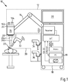
- Visualization system 10 shown is a surgical visualization system. It comprises an operating microscope 12 with a microscope unit 16 accommodated on a stand 14 and with an operating console 18 which contains a computer unit 19 with a touch-sensitive display 20.
- the surgical microscope 12 enables an observer to stereoscopically view an operation area 22 in a binocular view 24, which has eyepieces 102, 104, with a left and right optical observation beam path 26a, 26b, which passes through a common microscope objective 28.
- the device 30 contains a first, a second and a third video endoscope 32, 34, 36.
- the video endoscope 32 enables the operating area 22 to be examined by detecting white light scattered in the operating area 22 and the fluorescent light of the dye 5 excited to fluoresce -ALA in the operating area 22.
- the video endoscope 34 is used to examine the operating area 22 by detecting white light scattered in the operating area 22 and the fluorescent light of the fluorescent dye sodium fluorescein (NaFI).
- the video endoscope 36 is suitable for examining the operating area 22 by detecting in the operating area 22 scattered white light and the fluorescent light of the fluorescence-induced dye indiocyanin green (ICG) in the operating area 22.
- ICG fluorescence-induced dye indiocyanin green
- the touch-sensitive display 20 of the surgical microscope 12 enables on the one hand the control and setting of optical imaging parameters of the microscope unit 16 and the video endoscopes 32, 34 and 36 and on the other hand the separate or simultaneous visualization of the by means of a video endoscope 32, 34, 36 or object region 22 observed by microscope unit 16.
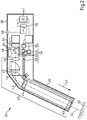
- the Fig. 2 shows the structure of the first video endoscope 32 Fig. 1 .
- the video endoscope 32 has an endoscope body 39 which extends in the longitudinal direction 37 and has a handle 38 connected to it, in which an electrical energy store 41 is arranged.
- the electrical energy storage 41 is a battery. In principle, however, it is also possible to provide a high-performance capacitor as an electrical energy store 41.
- the video endoscope 32 enables the object region 46 to be observed in a white light operating mode and in a fluorescent light operating mode.
- the video endoscope 32 contains observation optics 40, which has a lens assembly 42 and comprises an optical transmission system 44 with a folding mirror 45, around an image of an operating area 22, optionally an image sensor 48 sensitive to infrared light and an image sensor 50 sensitive to light in the visible spectral range feed.
- the lighting system 52 In order to illuminate the surgical area 22, there is an illumination system 52 in the video endoscope 32 with a white light LED 54 and with a light source 56 which provides light with which the fluorescent dye can be excited to fluorescence in a narrow band.
- the lighting system 52 contains a light guide 58 and has a switchable folding mirror 60, which makes it possible to illuminate the object area 46 optionally with the light from the white light LED 54 or the light source 56.
- a switchable emission filter 64 in the video endoscope 32 which can be switched in and out the optical imaging beam path 62 can be moved.
- the video endoscope 32 includes an activation circuit 66 which is arranged in the endoscope body 39.
- the activation circuit 66 has, as an activation sensor, a touch sensor 68 integrated in the grip piece 38, with which the recording of the video endoscope 32 on the grip piece 38 can be detected with the hand of an observer, in order then to move the video endoscope 32 out of a sleep mode into one To put work mode.
- the activation circuit 66 here effects an automatic coupling of the video endoscope 32 and the surgical microscope 12.
- the video endoscope 32 is registered by means of the activation circuit 66 on the computer unit 19 of the surgical microscope 12. It then wirelessly transmits electronic image data to the computer unit 19, which can be displayed on the touch-sensitive display 20 of the surgical microscope 12.
- the construction of the second video endoscope 34 and the third video endoscope 36 from Fig. 1 fundamentally corresponds to the design of the first video endoscope 32.
- the second video endoscope 34 and the third video endoscope 36 each contain a light source and an emission filter in addition to the white light LED, which are used to excite and detect fluorescent light of the dye 5 -ALA or NaFI are coordinated.
- there is an activation circuit with a touch sensor that has the functionality described above.
- the Fig. 3 explains the structure of the microscope unit 16 of the surgical microscope 12 in the visualization system 10.
- the microscope unit 16 enables stereoscopic observation of the operating area 22 with observation beam paths 70, 72 which penetrate a main microscope objective 74.
- a zoom system 76, 78 is provided in the microscope unit 16 to adjust the magnification in the observation beam paths 70, 72.
- the light emitted by the light source 82 is collimated with collimating optics 84 in the plane of a light field diaphragm 86 and guided via the condenser lens 88 and the main microscope objective 28 with the illuminating beam path 92 into the operating area 22.
- the lighting system 80 contains an adjustable filter wheel 94, which is adjustable by means of a drive 95 and which has different filters for setting the spectral composition of the illuminating light guided to the operating area 22.
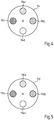
- the Fig. 4 shows the filter wheel 94 as a top view.
- the filter wheel 94 has a pinhole 96d and illumination filters 96a, 96b, 96c, with which the spectral composition of the illumination light can be adjusted so that the dye ICG or 5-ALA or NaFI can be excited to fluoresce and the light of the wavelength, that corresponds to the wavelength of the fluorescent light of these dyes, is filtered out.
- the filter wheel 112 includes the filters 116a, 116b, 116c and an aperture 116d.
- the transmission characteristic of the filters 116a, 116b, 116c is based on the transmission characteristic the illumination filter 96a, 96b, 96c matched.
- the filter 96a of the filter wheel 94 is switched into the illumination beam path 92 and the filter 116a of the filter wheel 112 is arranged in the left and right observation beam paths 70, 72 .
- the filter 96b is arranged in the illumination beam path 92 in the operation area 22 and the filter 116b of the corresponding filter wheel 112 is positioned in the left and right observation beam paths 70, 72, respectively.
- the filter 96c is switched into the illumination beam path 92 and the filter 116c of the filter wheel 112 is positioned in the left and right observation beam paths 70, 72.
- the microscope unit 16 there is a camera 108 for the detection of IR light and a camera 110 with which fluorescent light can be detected in the visible spectral range.
- the camera 108 and the camera 110 are with the in the Fig. 1 Computer unit 19 of the surgical microscope 12 shown connected.
- the Fig. 6a shows a display 118 of the display 20 triggered by the activation of a video endoscope 32, 34, 36. An observer is informed with which of the video endoscopes he is currently working.
- a display 118 of the display 20 is shown with buttons for controlling an activated video endoscope 32, 34, 36.
- the button 123 enables an operator to switch the correspondingly activated video endoscope 32, 34, 36 between the operating mode for observing the operating area 22 by means of white light and the operating mode for observing the operating area 22 by detecting fluorescent light.
- the operating mode of the microscope unit 16 is also switched from a white light operating mode to the fluorescent light operating mode and vice versa by means of the corresponding activation circuit.
- This measure has the effect that in the visualization system 10 the operating state of the surgical microscope 12 is always automatically matched to the operating state of the video endoscope 32, 34, 36 used.
- the Fig. 6c and Fig. 6d each show an observation image of a video endoscope 32, 34, 36 and an observation image of the microscope unit 16 on the display 20.
- the observation image of the video endoscope 32, 34, 36 and the microscope unit 16 is visualized in two separate fields 124, 126 that have different dimensions. By touching the respectively smaller field 126, an observer can selectively display the observation image of the microscope unit 16 or of the selected video endoscope 32, 34, 36 in the larger field 124.
- the visualization system can also provide for the observation image of the corresponding video endoscope 32, 34, 36 to be automatically displayed in the larger field 124, triggered by the recording or switching on of a specific video endoscope 32, 34, 36 by an observer becomes.
- the activation sensor 68 for a video endoscope 32, 34, 36 is integrated into the surgical microscope 12 and the activation circuit 66 is partly located in the surgical microscope 12 and in a video endoscope 32, 34, 36.
- the Fig. 6e shows the observation image of the video endoscope 32, 34, 36 as a full image 128.
- An observer can rotate this full image 128 by wiping a direction of rotation with the fingers of one hand on the display 20 or by moving a desired rotational position of the image 128, 128 'with the fingers of one hand on the display 20.
- a video endoscope 32, 34, 36 in an alternative embodiment of the surgical visualization system in the activation circuit 66 can also have a gyro sensor as an activation sensor instead of a touch sensor which detects a displacement of the corresponding video endoscope 32, 34, 36 this switches into a working state.
- a Hall sensor in the activation circuit with which it can be detected whether the corresponding video endoscope 32, 34, 36 is moved from a rest position, in which the video endoscope 32, 34, 36 in which Section of the Hall sensor is exposed to a defined magnetic field.
- a voice sensor can also be provided in the activation circuit 66 as the activation sensor in order to switch a video endoscope from an idle state to a working state.
- the Fig. 7 shows a further visualization system 10 'with an operating microscope 12 and with a device for capturing electronic image data with a first, a second and a third video endoscope 32', 34 ', 36'.
- modules of the visualization system 10 'and elements in the Fig. 5 Corresponding to elements and assemblies from the preceding figures, these are identified here with the same numbers as reference numerals.
- a cable 130 with a plug 132 and a socket 134 formed in the operating console 18 of the surgical microscope 12 is provided here.
- Inserting the plug 132 into the socket 134 actuates an activation circuit arranged in the corresponding video endoscope 32 ', 34', 36 'which, when activated, registers the corresponding one Video endoscope 32 ', 34', 36 'causes on the computer unit 19 of the surgical microscope 12 and sets a working mode for the corresponding video endoscope 32', 34 ', 36'.
- This measure then results in the display of the operating parameters of the corresponding video endoscope 32 ', 34', 36 'on the display 20 and thus enables the observation image to be displayed.
- the description relates to a visualization system 10, 10 ′ with an operating microscope 12 for observing an operating area 22 with magnification, which has a computer unit 19 with a display 20 for displaying image data.
- the visualization system 10, 10 ′ comprises a device 30 for acquiring endoscopic image data in the operating area 22, which is functionally coupled to the operating microscope 12 for displaying the endoscopic image data.
- the device 30 for acquiring endoscopic images in the operating area 22 contains a circuit 66 which is designed for acquiring actuation information and can be actuated by an observer and which, when the actuation information for the surgical microscope 12 is present, applies a circuit to the device 30 for acquiring endoscopic images in FIG adjusts the operating microscope operating state to the operating area 22.
Landscapes
- Health & Medical Sciences (AREA)
- Life Sciences & Earth Sciences (AREA)
- Physics & Mathematics (AREA)
- Surgery (AREA)
- Optics & Photonics (AREA)
- Engineering & Computer Science (AREA)
- General Health & Medical Sciences (AREA)
- Heart & Thoracic Surgery (AREA)
- Nuclear Medicine, Radiotherapy & Molecular Imaging (AREA)
- Biomedical Technology (AREA)
- Pathology (AREA)
- Medical Informatics (AREA)
- Molecular Biology (AREA)
- Animal Behavior & Ethology (AREA)
- Public Health (AREA)
- Veterinary Medicine (AREA)
- Chemical & Material Sciences (AREA)
- General Physics & Mathematics (AREA)
- Analytical Chemistry (AREA)
- Biophysics (AREA)
- Radiology & Medical Imaging (AREA)
- Oral & Maxillofacial Surgery (AREA)
- Multimedia (AREA)
- Mechanical Engineering (AREA)
- Endoscopes (AREA)
- Investigating, Analyzing Materials By Fluorescence Or Luminescence (AREA)
Description
- Die Erfindung betrifft ein Visualisierungssystem mit einem Operationsmikrogemäß des Anspruchs 1. Aus der
JP 2004 065317 A - Die
US 2002/0151784 A1 offenbart ein Visualisierungssystem mit einem Operationsmikroskop und mit einem Endoskop, bei dem durch Betätigung eines Schalters an dem Endoskop ein auf das Endoskop abgestimmter Betriebszustand des Operationsmikroskops eingestellt werden kann. - In der
US 6,398,721 B1 ist ein Operationsmikroskop beschrieben, das eine Mikroskopeinheit hat, die an einem Stativ aufgenommen ist und die optische Baugruppen für das Beobachten eines Operationsbereichs unter Vergrößerung mit einem optischen Beobachtungsstrahlengang enthält. Das Visualisierungssystem weist eine endoskopische Untersuchungseinrichtung auf, die als ein Video-Endoskop ausgebildet sein kann, das sich über in der Mikroskopeinheit ausgebildete elektrische Kontakte mit dem Operationsmikroskop verbinden lässt. - Die
US 2005/0020876 A1 und dieUS 2001/055062 derselben Patentfamilie offenbaren jeweils ein Visualisierungssystem mit einem Operationsmikroskop, das eine Mikroskopeinheit hat, in der endoskopische Bilddaten zur Anzeige gebracht werden können. Für das Erfassen der endoskopischen Bilddaten gibt es in diesem Visualisierungssystem ein an einer Stativeinrichtung aufgenommenes Endoskop. An dem Stativ kann die Lage des Endoskops zu dem Mikroskop referenziert werden. Dies ermöglicht ein orts- und lagerichtiges Visualisieren von Endoskopbildern in dem Beobachtungsbild des Operationsmikroskops. - Aufgabe der Erfindung ist es, ein Visualisierungssystem bereitzustellen und ein Verfahren für den Betrieb eines chirurgischen Visualisierungssystems anzugeben, mit dem einer Beobachtungsperson in einer chirurgischen Operation auf ergonomisch günstige Weise das Anzeigen endoskopischer Bilder ermöglicht wird.
- Diese Aufgabe wird mit dem in Anspruch 1 angegebenen Visualisierungssystem gelöst. Vorteilhafte Ausführungsformen der Erfindung sind in den abhängigen Ansprüchen angegeben.
- Unter einem Operationsmikroskop wird vorliegend ein System mit einer vorzugsweise als ein Stereomikroskop ausgebildeten Mikroskopeinheit verstanden, die an einem Stativ aufgenommen ist und die einer Beobachtungsperson das Beobachten eines Operationsbereichs mit Vergrößerung ermöglicht. Die Mikroskopeinheit kann für das Visualisieren des Operationsbereichs mit einem optischen Beobachtungsstrahlengang ausgelegt sein. Es ist jedoch auch möglich, eine Mikroskopeinheit vorzusehen, die einer Beobachtungsperson digital erfasste Bilder zur Anzeige bringt. Ein Beispiel für ein Operationsmikroskop im Sinne der Erfindung ist etwa das von der Carl Zeiss Meditec AG hergestellte und vertriebene System OPMI® Pentero®.
- Ein Endoskop im Sinne der Erfindung ist ein optisches Instrument zur Betrachtung und Untersuchung von Körperhöhlen. Endoskope im Sinne der Erfindung haben einen vorzugsweise in eine Längsrichtung erstreckten Endoskopkörper. Unter einem Video-Endoskop versteht die Erfindung ein Endoskop, welches das digitale Visualisieren von Körperhöhlen ermöglicht. Video-Endoskope enthalten eine Einrichtung für das Abbilden eines Operationsbereichs auf einem Bildsensor. Endoskopische Bilddaten im Sinne dieser Erfindung sind Bilddaten, die mit einem Video-Endoskop erfasst sind.
- Die Erfindung schlägt vor, dass das Visualisierungssystem einen für das Erfassen einer Betätigungsinformation ausgelegten und von einer Beobachtungsperson betätigbaren Schaltkreis enthält, der bei Vorliegen der Betätigungsinformation für das Operationsmikroskop einen auf die Einrichtung für das Erfassen von endoskopischen Bildern in dem Operationsbereich abgestimmten Operationsmikroskop-Betriebszustand einstellt.
- Der Schaltkreis kann z. B. vollständig oder teilweise in der Einrichtung für das Erfassen von endoskopischen Bildern in dem Operationsbereich angeordnet sein.
- Ein auf die Einrichtung für das Erfassen von endoskopischen Bildern in dem Operationsbereich abgestimmter Operationsmikroskop-Betriebszustand kann z. B. in einer bestimmten Einstellung eines Systems für das Einstellen der Vergrößerung des Beobachtungsbildes des Operationsmikroskops (Vergrößerungssystem), in einer bestimmten Einstellung eines Beleuchtungssystems, das Beleuchtungslicht für das Beleuchten des Objektbereichs des Operationsmikroskops bereitstellt, oder in einer bestimmten Einstellung von Filtern in einem Beleuchtungsstrahlengang und/oder in einem Beobachtungsstrahlengang des Operationsmikroskops oder auch in einer bestimmten Konfiguration eines Displays des Operationsmikroskops bestehen.
- Der Schaltkreis kann dabei ein Aktivierungsschaltkreis sein, der die Einrichtung für das Erfassen der endoskopischen Bilder aus einem Ruhezustand in einen Aktivierungszustand versetzt und der einen Aktivierungssensor enthält. Eine Idee der Erfindung ist es dabei, den Aktivierungssensor als einen Sensor aus der Gruppe Gyrosensor, Hallsensor, Berührungssensor oder Sprachsensor auszubilden.
- Erfindungsgemäß wird vorgeschlagen, dass die Einrichtung für das Erfassen von endoskopischen Bildern in dem Operationsbereich wenigstens ein Endoskop aufweist. In diesem Fall ist der Aktivierungssensor bevorzugt in einem Endoskopkörper des Endoskops angeordnet. Es sei allerdings bemerkt, dass der Aktivierungssensor auch in dem Operationsmikroskop selbst angeordnet sein kann.
- Eine Idee der Erfindung ist es, dass die Einrichtung für das Erfassen von endoskopischen Bildern in dem Operationsbereich wenigstens ein Endoskop enthält, das in einem ersten Betriebszustand das Untersuchen von in dem Operationsbereich gestreuten Weißlicht und das in einem von dem ersten Betriebszustand verschiedenen weiteren Endoskop-Betriebszustand das Untersuchen von Fluoreszenzlicht in einem definierten Wellenlängenbereich eines zu Fluoreszenz angeregten Farbstoffs wie etwa 5-ALA, Natriumfluorscein (NaFl), oder auch Indocyaningrün (ICG) in dem Operationsbereich und/oder das Untersuchen von Autofluoreszenzlicht in dem definierten Wellenlängenbereich von biologischem Gewebe und/oder Objekten in dem Operationsbereich ermöglicht.
- Der Farbstoff 5-ALA wird z. B. mit Licht der Wellenlänge 400nm ≤ λ ≤ 410 nm zu Fluoreszenz angeregt. Für die Wellenlänge λ des Fluoreszenzlichts gilt dann 620 ≤ λ ≤ 710 nm. Der Farbstoff NaFI wird mit Licht der Wellenlänge 460nm ≤ λ ≤ 500 nm zu Fluoreszenz angeregt. Dabei entsteht Fluoreszenzlicht in dem Wellenlängenbereich 540 ≤ λ ≤ 690 nm. Für die Fluoreszenzanregung des Farbstoffs ICG muss dieser mit Licht der Wellenlänge 700nm ≤ λ ≤ 780nm beaufschlagt werden. Die Wellenlänge λ des ausgesendeten Fluoreszenzlichts liegt dann in dem Wellenlängenbereich 820nm ≤ λ ≤ 900 nm.
- Eine Idee der Erfindung ist, dass das Operationsmikroskop in einem ersten Operationsmikroskop-Betriebszustand das Untersuchen von in dem Operationsbereich gestreuten Weißlicht und das in einem von dem ersten Betriebszustand verschiedenen weiteren Operationsmikroskop-Betriebszustand das Untersuchen von Fluoreszenzlicht in einem definierten Wellenlängenbereich eines zu Fluoreszenz angeregten ersten Farbstoffs, z. B. 5-ALA in dem Operationsbereich und/oder das Untersuchen einer Autofluoreszenz in dem definierten Wellenlängenbereich von biologischem Gewebe und/oder Objekten in dem Operationsbereich ermöglicht. Dabei ist das Endoskop erfindungsgemäß so ausgelegt, dass in einem ersten Endoskop-Betriebszustand das Untersuchen von in dem Operationsbereich gestreutem Weißlicht und in einem von dem ersten Betriebszustand verschiedenen weiteren Endoskop-Betriebszustand das Untersuchen von Fluoreszenzlicht in dem definierten Wellenlängenbereich des zu Fluoreszenz angeregten ersten Farbstoffs, z. B. 5-ALA in dem Operationsbereich und/oder das Untersuchen von Autofluoreszenzlicht in dem definierten Wellenlängenbereich von biologischem Gewebe und/oder Objekten in dem Operationsbereich möglich ist. Der weitere Endoskop-Betriebszustand und der weitere Operationsmikroskop-Betriebszustand sind also aufeinander abgestimmt. Erfindungsgemäß sind das Operationsmikroskop und das Endoskop dabei derart wirkungsgekoppelt, dass bei Einstellen des weiteren Endoskop-Betriebszustands der weitere Operati-onsmikroskop-Betriebszustand automatisch, d. h. ausgelöst durch das Einstellen des weiteren Endoskop-Betriebszustands eingestellt wird.
- Es ist außerdem eine Idee der Erfindung, in dem Visualisierungssystem eine Einrichtung für das automatische Wirkungskoppeln des Operationsmikroskops und dem ersten Endoskop bei einem Aktivieren des Endoskops und/oder bei einem Aufnehmen des Endoskops durch die Beobachtungsperson und/oder bei einem Anordnen eines Abschnitts des Endoskops in einem Beobachtungsbereich des Operationsmikroskops und/oder bei einem Auftreten von Fluoreszenzlicht und/oder Autofluoreszenzlicht in dem definierten Wellenlängenbereich vorzusehen.
- Erfindungsgemäß wird auch vorgeschlagen, dass es in dem Visualisierungssystem ein weiteres Endoskop gibt, das in wenigstens einem Endoskop-Betriebszustand das Untersuchen von Fluoreszenzlicht in einem definierten weiteren Wellenlängenbereich eines zu Fluoreszenz angeregten weiteren Farbstoffs, z. B. NaFI in dem Operationsbereich und/oder das Untersuchen von Autofluoreszenzlicht in dem definierten weiteren Wellenlängenbereich von biologischem Gewebe und/oder Objekten in dem Operationsbereich ermöglicht, wobei das Operationsmikroskop in einem von dem ersten Betriebszustand verschiedenen weiteren Operationsmikroskop-Betriebszustand das Untersuchen von Fluoreszenzlicht in dem definierten Wellenlängenbereich des zu Fluoreszenz angeregten weiteren Farbstoffs, z. B. NaFI in dem Operationsbereich und/oder das Untersuchen einer Autofluoreszenz in dem definierten Wellenlängenbereich von biologischem Gewebe und/oder Objekten in dem Operationsbereich ermöglicht, und wobei das Operationsmikroskop und das Endoskop derart wirkungskoppelbar sind, dass bei einem Betrieben des Endoskops in diesen weiteren Endoskop-Betriebszustand der weitere Operationsmikroskop-Betriebszustand automatisch eingestellt wird. Eine Idee der Erfindung ist es dabei insbesondere, dass die Einrichtung für das automatische Wirkungskoppeln des Operationsmikroskops und des weiteren Endoskops bei einem Aktivieren des weiteren Endoskops und/oder bei einem Aufnehmen des weiteren Endoskops durch die Beobachtungsperson und/oder bei einem Anordnen eines Abschnitts des weiteren Endoskops in einem Beobachtungsbereich des Operationsmikroskops und/oder bei einem Auftreten von Fluoreszenzlicht und/oder Autofluoreszenzlicht in dem definierten Wellenlängenbereich automatisch, d. h. ausgelöst durch das Aufnehmen des weiteren Endoskops und/oder das Anordnen eines Abschnitts des weiteren Endoskops in dem Beobachtungsbereich und/oder durch das Auftreten von Fluoreszenzlicht und/oder Autofluoreszenzlicht bewirkt wird.
- In dem Visualisierungssystem kann insbesondere auch ein weiteres Endoskop vorgesehen sein, das in wenigstens einem Endoskop-Betriebszustand das Untersuchen von Fluoreszenzlicht in einem definierten weiteren Wellenlängenbereich eines zu Fluoreszenz angeregten weiteren Farbstoffs z. B. ICG in dem Operationsbereich und/oder das Untersuchen von Autofluoreszenzlicht in dem definierten weiteren Wellenlängenbereich von biologischem Gewebe und/oder Objekten in dem Operationsbereich ermöglicht, wobei das Operationsmikroskop in einem von dem ersten Betriebszustand verschiedenen weiteren Operationsmikroskop-Betriebszustand das Untersuchen von Fluoreszenzlicht in dem definierten weiteren Wellenlängenbereich des zu Fluoreszenz angeregten weiteren Farbstoffs, z. B. ICG in dem Operationsbereich und/oder das Untersuchen einer Autofluoreszenz in dem definierten Wellenlängenbereich von biologischem Gewebe und/oder Objekten in dem Operationsbereich ermöglicht, und wobei das Operationsmikroskop und das Endoskop derart wirkungskoppelbar sind, dass bei einem Betreiben des Endoskops in diesem Endoskop-Betriebszustand der weitere Operationsmikroskop-Betriebszustand automatisch eingestellt wird.
Eine Idee der Erfindung ist hier wiederum das automatische Wirkungskoppeln des Operationsmikroskops und des weiteren Endoskops bei einem Aktivieren des weiteren Endoskops und/oder bei einem Aufnehmen des weiteren Endoskops durch die Beobachtungsperson und/oder bei einem Anordnen eines Abschnitts des weiteren Endoskops in einem Beobachtungsbereich des Operationsmikroskops und/oder bei einem Auftreten von Fluoreszenzlicht und/oder Autofluoreszenzlicht in dem definierten weiteren Wellenlängenbereich.
In dem erfindungsgemäßen Visualisierungssystem kann das wenigstens eine Endoskop insbesondere als ein Video-Endoskop ausgebildet sein.
Es wird darüber hinaus vorgeschlagen, dass das Visualisierungssystem auch eine Einrichtung für das Drehen eines an einem Display angezeigten endoskopischen Bilds aus dem Operationsbereich relativ zu dem Display hat. - Bei einem Verfahren zum Betrieb eines Visualisierungssystems, das ein Operationsmikroskop für das Beobachten eines Operationsbereichs mit Vergrößerung enthält und das eine Einrichtung für das Erfassen von endoskopischen Bilddaten in dem Operationsbereich aufweist, die für das Anzeigen der endoskopischen Bilddaten mit dem Operationsmikroskop wirkungsgekoppelt ist, wird bei einem Verstellen wenigstens eines Betriebsparameters des Video-Endoskops wenigstens ein Betriebsparameter des Operationsmikroskops verändert und/oder bei einem Verstellen wenigstens eines Betriebsparameters des Operationsmikroskops wenigstens einen Betriebsparameter des Video-Endoskops variiert.
- Nachfolgend werden vorteilhafte Ausführungsbeispiele der Erfindung beschrieben, die in den Zeichnungen schematisch dargestellt sind.
- Es zeigen:
- Fig. 1
- ein erstes Visualisierungssystem mit einem Operationsmikroskop und mit einer Einrichtung für das Erfassen von endoskopischen Bilddaten mit einem ersten, mit einem zweiten und mit einem dritten Video-Endoskop;
- Fig. 2
- das erste Video-Endoskop in der Einrichtung für das Erfassen von elektronischen Bilddaten als Schnitt;
- Fig.3
- den Aufbau des Operationsmikroskops in dem chirurgischen Visualisierungssystem;
- Fig. 4
- ein Filterrad eines Beleuchtungssystems in dem Operationsmikroskop;
- Fig. 5
- ein in einem Beobachtungsstrahlengang des Operationsmikroskops angeordnetes Filterrad;
- Fig. 6a
- und
Fig. 6b sowieFig. 6c undFig. 6d verschiedene Anzeigen an einem Display des Operationsmikroskops; und - Fig. 7
- ein weiteres Visualisierungssystem mit einem Operationsmikroskop und mit einer Einrichtung für das Erfassen von endoskopischen Bilddaten mit einem ersten, mit einem zweiten und mit einem dritten Video-Endoskop.
- Das in der
Fig. 1 gezeigte Visualisierungssystem 10 ist ein chirurgisches Visualisierungssystem. Es umfasst ein Operationsmikroskop 12 mit einer an einem Stativ 14 aufgenommenen Mikroskopeinheit 16 und mit einer Bedienkonsole 18, die eine Rechnereinheit 19 mit einem berührungssensitiven Display 20 enthält. Das Operationsmikroskop 12 ermöglicht einer Beobachtungsperson das stereoskopische Betrachten eines Operationsbereichs 22 in einem Binokulareinblick 24, der Okulare 102, 104 hat, mit einem linken und rechten optischen Beobachtungsstrahlengang 26a, 26b, der ein gemeinsames Mikroskop-Hauptobjektiv 28 durchsetzt. - In dem Visualisierungssystem 10 gib es eine Einrichtung 30 für das Erfassen von endoskopischen Bilddaten. Die Einrichtung 30 enthält ein erstes, ein zweites und ein drittes Video-Endoskop 32, 34, 36. Das Video-Endoskop 32 ermöglicht das Untersuchen des Operationsbereichs 22 durch Erfassen von in dem Operationsbereich 22 gestreuten Weißlicht und des Fluoreszenzlichts des zu Fluoreszenz angeregten Farbstoffs 5-ALA in dem Operationsbereich 22.
- Das Video-Endoskop 34 dient für das Untersuchen des Operationsbereichs 22 durch Erfassen von in dem Operationsbereich 22 gestreuten Weißlicht und des Fluoreszenzlichts des zu Fluoreszenz angeregten Farbstoffs Natriumfluoreszein (NaFI).
- Das Video-Endoskop 36 eignet sich für das Untersuchen des Operationsbereichs 22 durch Erfassen von in dem Operationsbereich 22 gestreuten Weißlicht und des Fluoreszenzlichts des zu Fluoreszenz angeregten Farbstoffs IndiocyaninGrün (ICG) in dem Operationsbereich 22.
- Das berührungssensitive Display 20 des Operationsmikroskops 12 ermöglicht zum einen das Steuern und Einstellen von optischen Abbildungsparametern der Mikroskopeinheit 16 sowie der Video-Endoskope 32, 34 und 36 und zum anderen das getrennte oder zeitgleiche Visualisieren des mittels eines Video-Endoskops 32, 34, 36 oder mittels der Mikroskopeinheit 16 beobachteten Objektbereichs 22.
- Die
Fig. 2 zeigt den Aufbau des ersten Video-Endoskops 32 ausFig. 1 . Das Video-Endoskop 32 hat einen in die Längsrichtung 37 erstreckten Endoskopkörper 39 mit einem daran angeschlossenen Griffstück 38, in dem ein elektrischer Energiespeicher 41 angeordnet ist. Der elektrische Energiespeicher 41 ist eine Batterie. Grundsätzlich ist es allerdings auch möglich, einen Hochleistungs-Kondensator als elektrischen Energiespeicher 41 vorzusehen. Das Video-Endoskop 32 ermöglicht das Beobachten des Objektbereichs 46 in einem Weißlichtbetriebsmodus und in einem Fluoreszenzlichtbetriebsmodus. Hierfür enthält das Video-Endoskop 32 eine Beobachtungsoptik 40, die eine Objektivbaugruppe 42 aufweist und ein optisches Übertragungssystem 44 mit einem Klappspiegel 45 umfasst, um ein Bild eines Operationsbereichs 22 wahlweise einem für Infrarotlicht sensitiven Bildsensor 48 und einem für Licht im sichtbaren Spektralbereich sensitiven Bildsensor 50 zuzuführen. - Um den Operationsbereich 22 zu beleuchten, gibt es in dem Video-Endoskop 32 ein Beleuchtungssystem 52 mit einer Weißlicht-LED 54 und mit einer Lichtquelle 56, die Licht bereitstellt, mit dem der Fluoreszenzfarbstoff schmalbandig zu Fluoreszenz angeregt werden kann. Das Beleuchtungssystem 52 enthält hierfür einen Lichtleiter 58 und weist einen schaltbaren Klappspiegel 60 auf, der es ermöglicht, den Objektbereich 46 wahlweise mit dem Licht der Weißlicht-LED 54 oder der Lichtquelle 56 zu beleuchten. Um das von fluoreszierenden Objekten, z. B. dem Farbstoff ICG, ausgehende Fluoreszenzlicht, das in dem Operationsbereich 22 gestreut wird und das durch die Objektivbaugruppe 42 in das Übertragungssystem 44 gelangt, unterdrücken zu können, gibt es in dem Video-Endoskop 32 ein schaltbares Emissionsfilter 64, das wahlweise in und aus dem optischen Abbildungsstrahlengang 62 bewegt werden kann.
- Das Video-Endoskop 32 enthält einen Aktivierungsschaltkreis 66, der in dem Endoskopkörper 39 angeordnet ist. Der Aktivierungsschaltkreis 66 weist als Aktivierungssensor einen in das Griffstück 38 integrierten Berührungssensor 68 auf, mit dem das Aufnehmen des Video-Endoskops 32 an dem Griffstück 38 mit der Hand einer Beobachtungsperson erfasst werden kann, um das Video-Endoskop 32 dann aus einem Ruhemodus in einen Arbeitsmodus zu versetzen. Der Aktivierungsschaltkreis 66 bewirkt hier ein automatisches wirkungskoppeln des Video-Endoskops 32 und des Operationsmikroskops 12. Das Video-Endoskop 32 wird mittels des Aktivierungsschaltkreises 66 an der Rechnereinheit 19 des Operationsmikroskops 12 angemeldet. Es übermittelt dann an die Rechnereinheit 19 drahtlos elektronische Bilddaten, die an dem berührungssensitiven Display 20 des Operationsmikroskops 12 angezeigt werden können.
- Wenn eine Beobachtungsperson das Griffstück 38 mit der Hand freigibt, wird dies mittels des Berührungssensors 68 erfasst. Der Aktivierungsschaltkreis 66 versetzt dann das Video-Endoskop 32 wieder in den Ruhemodus. Auf diese Weise kann der elektrische Energieverbrauch des Video-Endoskops 32 minimiert werden, wenn dieses lediglich bereitgestellt, nicht aber benutzt wird.
- Der Aufbau des zweiten Video-Endoskops 34 und des dritten Video-Endoskops 36 aus
Fig. 1 entspricht grundsätzlich dem Aufbau des ersten Video-Endoskops 32. Das zweite Video-Endoskop 34 und das dritte Video-Endoskop 36 enthalten dabei allerdings neben der Weißlicht-LED jeweils eine Lichtquelle und ein Emissionsfilter, die für das Anregen und Detektieren von Fluoreszenzlicht des Farbstoffs 5-ALA bzw. NaFI abgestimmt sind. Auch hier gibt es einen Aktivierungsschaltkreis mit einem Berührungssensor, der die vorstehend beschriebene Funktionalität hat. - Die
Fig. 3 erläutert den Aufbau der Mikroskopeinheit 16 des Operationsmikroskops 12 in dem Visualisierungssystem 10. Die Mikroskopeinheit 16 ermöglicht das stereoskopische Beobachten des Operationsbereichs 22 mit Beobachtungsstrahlengängen 70, 72, die ein Mikroskop-Hauptobjektiv 74 durchsetzen. In der Mikroskopeinheit 16 ist zu einer Einstellung der Vergrößerung in den Beobachtungsstrahlengängen 70, 72 ein Zoomsystem 76, 78 vorgesehen. Für das Beleuchten des Operationsbereichs 22 mit Beleuchtungslicht gibt es in der Mikroskopeinheit 16 ein Beleuchtungssystem 80 mit einer Lichtquelle 82. - Das von der Lichtquelle 82 ausgesendete Licht wird mit einer Kollimationsoptik 84 in der Ebene einer Leuchtfeldblende 86 kollimiert und über die Kondensorlinse 88 und das Mikroskop-Hauptobjektiv 28 mit dem Beleuchtungsstrahlengang 92 in den Operationsbereich 22 geführt. Das Beleuchtungssystem 80 enthält ein verstellbares Filterrad 94, das mittels eines Antriebs 95 verstellbar ist und das unterschiedliche Filter für das Einstellen der spektralen Zusammensetzung des zu dem Operationsbereich 22 geführten Beleuchtungslichts aufweist.
- Die
Fig. 4 zeigt das Filterrad 94 als Draufsicht. Das Filterrad 94 hat eine Lochblende 96d und Beleuchtungsfilter 96a, 96b, 96c, mit denen die spektrale Zusammensetzung des Beleuchtungslichts so eingestellt werden kann, dass sich damit der Farbstoff ICG oder 5-ALA bzw. NaFI zu Fluoreszenz anregen lässt und das Licht der Wellenlänge, das der Wellenlänge des Fluoreszenzlichts dieser Farbstoffe entspricht, dabei ausgefiltert ist. - In dem linken und rechten Beobachtungsstrahlengang 70, 72 der Mikroskopeinheit 16 gibt es jeweils ein verstellbares Filterrad 112. Die
Fig. 5 zeigt das Filterrad 112 als Draufsicht. Das Filterrad 112 enthält die Filter 116a, 116b, 116c und eine Lochblende 116d. Die Transmissionscharakteristik der Filter 116a, 116b, 116c ist auf die Transmissionscharakteristik der Beleuchtungsfilter 96a, 96b, 96c abgestimmt. Mittels der Filter 116a, 116b, 116c wird das die Fluoreszenz des Farbstoffs ICG oder 5-ALA bzw. NaFI anregende Licht unterdrückt und das Licht der Wellenlänge des Fluoreszenzlichts dieser Farbstoffe hindurchgelassen. - Um in dem Operationsbereich 22 mittels Fluoreszenzlicht Gewebestrukturen zu visualisieren, die mit dem Farbstoff 5-ALA angereichert sind, wird das Filter 96a des Filterrads 94 in den Beleuchtungsstrahlengang 92 geschaltet und das Filter 116a des Filterrads 112 in dem linken und rechten Beobachtungsstrahlengang 70, 72 angeordnet. Entsprechend wird für das Visualisieren von mit dem Farbstoff ICG angereicherten Gewebestrukturen in dem Operationsbereich 22 das Filter 96b in dem Beleuchtungsstrahlengang 92 angeordnet und das Filter 116b des entsprechenden Filterrads 112 in dem linken bzw. rechten Beobachtungsstrahlengang 70, 72 positioniert. Für das Visualisieren von Gewebestrukturen, die den Farbstoff NaFI enthalten, wird das Filter 96c in den Beleuchtungsstrahlengang 92 geschaltet und das Filter 116c des Filterrads 112 in dem linken und rechten Beobachtungsstrahlengang 70, 72 positioniert.
- In der Mikroskopeinheit 16 gibt es eine Kamera 108 für das Erfassen von IR-Licht und eine Kamera 110, mit der Fluoreszenzlicht in dem sichtbaren Spektralbereich erfasst werden kann. Die Kamera 108 und die Kamera 110 ist mit der in der
Fig. 1 gezeigten Rechnereinheit 19 des Operationsmikroskops 12 verbunden. - Die
Fig. 6a zeigt eine durch das Aktivieren eines Video-Endoskops 32, 34, 36 ausgelöste Anzeige 118 des Displays 20. Eine Beobachtungsperson wird damit informiert, mit welchem der Video-Endoskope sie gerade arbeitet. - In der
Fig. 6b ist eine Anzeige 118 des Displays 20 mit Schaltflächen für das Steuern eines aktivierten Video-Endoskops 32, 34, 36 gezeigt. Die Schaltfläche 123 ermöglicht einer Bedienperson das Umschalten des entsprechend aktivierten Video-Endoskops 32, 34, 36 zwischen dem Betriebsmodus für das Beobachten des Operationsbereichs 22 mittels Weißlicht und dem Betriebsmodus für das Beobachten des Operationsbereichs 22 durch Erfassen von Fluoreszenzlicht. Dabei wird bei einem Umschalten eines Video-Endoskops 32, 34, 36 zwischen dem Weißlichtbetriebsmodus und dem Fluoreszenzlichtbetriebsmodus mittels des entsprechenden Aktivierungsschaltkreises auch der Betriebsmodus der Mikroskopeinheit 16 von einem Weißlichtbetriebsmodus in den Fluoreszenzlichtbetriebsmodus und umgekehrt geschaltet. Diese Maßnahme bewirkt, dass in dem Visualisierungssystem 10 der Betriebszustand des Operationsmikroskops 12 auf den Betriebszustand des eingesetzten Video-Endoskops 32, 34, 36 immer automatisch abgestimmt ist. - Die
Fig. 6c undFig. 6d zeigen jeweils ein Beobachtungsbild eines Video-Endoskops 32, 34, 36 und ein Beobachtungsbild der Mikroskopeinheit 16 an dem Display 20. Hier wird das Beobachtungsbild des Video-Endoskops 32, 34, 36 und der Mikroskopeinheit 16 in zwei voneinander getrennten Feldern 124, 126 visualisiert, die unterschiedliche Abmessungen haben. Durch Berühren des jeweils kleineren Feldes 126 kann eine Beobachtungsperson hier in dem größeren Feld 124 wahlweise das Beobachtungsbild der Mikroskopeinheit 16 oder des ausgewählten Video-Endoskops 32, 34, 36 zur Anzeige bringen. - Optional kann bei dem Visualisierungssystem auch vorgesehen sein, dass ausgelöst durch das Aufnehmen oder Einschalten eines bestimmten Video-Endoskops 32, 34, 36 durch eine Beobachtungsperson das Beobachtungsbild des entsprechenden Video-Endoskops 32, 34, 36 in dem größeren Feld 124 automatisch zur Anzeige gebracht wird. In diesem Fall ist also der Aktivierungssensor 68 für ein Video-Endoskop 32, 34, 36 in das Operationsmikroskop 12 integriert und es befindet sich der Aktivierungsschaltkreis 66 jeweils teilweise in dem Operationsmikroskop 12 und in einem Video-Endoskop 32, 34, 36.
- Die
Fig. 6e zeigt das Beobachtungsbild des Video-Endoskops 32, 34, 36 als ein Vollbild 128. Eine Beobachtungsperson kann dieses Vollbild 128 drehen, indem sie mit den Fingern einer Hand einer Drehrichtung folgend über das Display 20 wischt oder indem sie eine gewünschte Drehposition des Bilds 128, 128' mit den Fingern einer Hand an dem Display 20 antippt. - Es sei bemerkt, dass ein Video-Endoskop 32, 34, 36 in einer alternativen Ausführungsform des chirurgischen Visualisierungssystems in dem Aktivierungsschaltkreis 66 als Aktivierungssensor anstelle eines Berührungssensors auch einen Gyrosensor aufweisen kann, der bei Erfassen einer Verlagerung des entsprechenden Video-Endoskops 32, 34, 36 dieses in einen Arbeitszustand schaltet. Alternativ hierzu ist es auch möglich, in dem Aktivierungsschaltkreis einen Hallsensor vorzusehen, mit dem erfasst werden kann, ob das entsprechende Video-Endoskop 32, 34, 36 aus einer Ruheposition bewegt wird, in der das Video-Endoskop 32, 34, 36 in dem Abschnitt des Hallsensors einem definierten Magnetfeld ausgesetzt ist. Außerdem sei bemerkt, dass anstelle der vorgenannten Sensoren in dem Aktivierungsschaltkreis 66 als Aktivierungssensor auch ein Sprachsensor vorgesehen sein kann, um ein Video-Endoskop aus einem Ruhezustand in einen Arbeitszustand zu schalten.
- Die
Fig. 7 zeigt ein weiteres Visualisierungssystem 10' mit einem Operationsmikroskop 12 und mit einer Einrichtung für das Erfassen von elektronischen Bilddaten mit einem ersten, einem zweiten sowie einem dritten Video-Endoskop 32', 34', 36'. Soweit Baugruppen des Visualisierungssystems 10' und Elemente in derFig. 5 Elementen und Baugruppen aus den vorstehenden Figuren entsprechen, sind diese hier mit den gleichen Zahlen als Bezugszeichen kenntlich gemacht. Für den Anschluss der Video-Endoskope 32', 34', 36' an das Operationsmikroskop 12 ist hier ein Kabel 130 mit einem Stecker 132 und einer in der Bedienkonsole 18 des Operationsmikroskops 12 ausgebildete Steckdose 134 vorgesehen. Das Einstecken des Steckers 132 in die Steckdose 134 betätigt hier einen in dem entsprechenden Video-Endoskop 32', 34', 36' angeordneten Aktivierungsschaltkreis, der bei Aktivierung das Anmelden des entsprechenden Video-Endoskops 32', 34', 36' an der Rechnereinheit 19 des Operationsmikroskops 12 bewirkt und für das entsprechende Video-Endoskop 32', 34', 36' einen Arbeitsbetriebsmodus einstellt. Diese Maßnahme hat dann das Anzeigen der Betriebsparameter des entsprechenden Video-Endoskops 32', 34', 36' an dem Display 20 zur Folge und ermöglicht so das Anzeigen von dessen Beobachtungsbild. Umgekehrt, wenn die Steckerverbindung von Video-Endoskop 32', 34', 36' und Operationsmikroskop 12 geöffnet wird, hat dies ein Abmelden des entsprechenden Video-Endoskops 32', 34', 36' an dem Operationsmikroskop 12 zur Folge und das entsprechende Video-Endoskop wird in einen Ruhemodus versetzt. - Zusammenfassend ist insbesondere folgendes festzuhalten: Die Beschreibung betrifft ein Visualisierungssystem 10, 10' mit einem Operationsmikroskop 12 für das Beobachten eines Operationsbereichs 22 mit Vergrößerung, das eine Rechnereinheit 19 mit einem Display 20 zum Anzeigen von Bilddaten aufweist. Das Visualisierungssystem 10, 10' umfasst eine Einrichtung 30 für das Erfassen von endoskopischen Bilddaten in dem Operationsbereich 22, die für das Anzeigen der endoskopischen Bilddaten mit dem Operationsmikroskop 12 wirkungsgekoppelt ist. Die Einrichtung 30 für das Erfassen von endoskopischen Bildern in dem Operationsbereich 22 enthält einen für das Erfassen einer Betätigungsinformation ausgelegten und von einer Beobachtungsperson betätigbaren Schaltkreis 66, der bei Vorliegen der Betätigungsinformation für das Operationsmikroskop 12 einen auf die Einrichtung 30 für das Erfassen von endoskopischen Bildern in dem Operationsbereich 22 abgestimmten Operationsmikroskop-Betriebszustand einstellt.
-
- 10, 10'
- Visualisierungssystem
- 12
- Operationsmikroskop
- 14
- Stativ
- 16
- Mikroskopeinheit
- 18
- Bedienkonsole
- 19
- Rechnereinheit
- 20
- Display
- 22
- Operationsbereich
- 24
- Binokulareinblick
- 26a, 26b
- Beobachtungsstrahlengang
- 28
- Mikroskop-Hauptobjektiv
- 30
- Einrichtung zum Erfassen endoskopischer Bilddaten
- 32, 32', 32", 34, 34, 36, 36'
- Video-Endoskop
- 37
- Längsrichtung
- 38
- Griffstück
- 39
- Endoskopkörper
- 40
- Beobachtungsoptik
- 41
- elektrischer Energiespeicher
- 42
- Objektivbaugruppe
- 44
- optisches Übertragungssystem
- 45
- Klappspiegel
- 46
- Objektbereich
- 48, 50
- Bildsensor
- 52
- Beleuchtungssystem
- 54
- Weißlicht-LED
- 56
- Lichtquelle
- 58
- Lichtleiter
- 60
- Klappspiegel
- 62
- Abbildungsstrahlengang
- 64
- Emissionsfilter
- 66
- Aktivierungsschaltkreis
- 68
- Berührungssensor
- 70, 72
- Beobachtungsstrahlengang
- 74
- Mikroskop-Hauptobjektiv
- 76, 78
- Zoomsystem
- 80
- Beleuchtungssystem
- 82
- Lichtquelle
- 84
- Kollimationsoptik
- 86
- Leuchtfeldblende
- 88
- Kondensorlinse
- 92
- Beleuchtungsstrahlengang
- 94
- Filterrad
- 95
- Antrieb
- 96a, 96b, 96c
- Filter
- 96d
- Blende
- 102, 104
- Okular
- 108, 110
- Kamera
- 112
- Filterrad
- 116a, 116b, 116c
- Filter
- 116d
- Lochblende
- 118
- Anzeige
- 123
- Schaltfläche
- 124, 126
- Feld
- 128, 128'
- Bild
- 130
- Kabel
- 132
- Stecker
- 134
- Steckdose
Claims (12)
- Visualisierungssystem (10, 10')
mit einem Operationsmikroskop (12) eingerichtet zum Beobachten eines Operationsbereichs (22) mit Vergrößerung, das eine Rechnereinheit (19) mit einem Display (20) eingerichtet zum Anzeigen von Bilddaten enthält; und
mit einer Einrichtung (30) eingerichtet zum Erfassen von endoskopischen Bildern, die mit dem Operationsmikroskop (12) wirkungsgekoppelt ist und die wenigstens ein Endoskop (32, 32', 32") aufweist;
und mit einem für das Erfassen einer Betätigungsinformation ausgelegten und von einer Beobachtungsperson betätigbaren Schaltkreis (66), der bei Vorliegen der Betätigungsinformation für das Operationsmikroskop (12) einen auf die Einrichtung (30) für das Erfassen von endoskopischen Bildern in dem Operationsbereich (22) abgestimmten Operationsmikroskop-Betriebszustand einstellt;
dadurch gekennzeichnet, dass
das Operationsmikroskop (12) in einem ersten Operationsmikroskop-Betriebszustand zum Untersuchen von in dem Operationsbereich (22) gestreuten Weißlicht eingerichtet ist, und das in einem von dem ersten Betriebszustand verschiedenen weiteren Operationsmikroskop-Betriebszustand zum Untersuchen von Fluoreszenzlicht in einem definierten Wellenlängenbereich eines zu Fluoreszenz angeregten ersten Farbstoffs (5-ALA) in dem Operationsbereich (22) und/oder das Untersuchen einer Autofluoreszenz in dem definierten Wellenlängenbereich von biologischem Gewebe und/oder Objekten in dem Operationsbereich (22) eingerichtet ist, wobei das Endoskop (32, 32', 34, 34' 36, 36') in einem Endoskop-Betriebszustand zum Untersuchen von Fluoreszenzlicht in dem definierten Wellenlängenbereich des zu Fluoreszenz angeregten ersten Farbstoffs (5-ALA) in dem Operationsbereich (22) und/oder das Untersuchen von Autofluoreszenzlicht in dem definierten Wellenlängenbereich von biologischem Gewebe in dem Operationsbereich (22) eingerichtet ist, und wobei das Operationsmikroskop (12) und das Endoskop (32, 32', 34, 34' 36, 36') derart wirkungsgekoppelt sind, dass bei einem Betreiben des Endoskops (32, 32', 34, 34', 36, 36') in diesem Endoskop-Betriebszustand der weitere Operationsmikroskop-Betriebszustand automatisch eingestellt wird. - Visualisierungssystem nach Anspruch 1, dadurch gekennzeichnet, dass der Schaltkreis ein Aktivierungsschaltkreis (66) ist, der die Einrichtung für das Erfassen der endoskopischen Bilder aus einem Ruhezustand in einen Aktivierungszustand versetzt, wobei der Aktivierungsschaltkreis (66) einen Aktivierungssensor aus der Gruppe Gyrosensor, Hallsensor, Berührungssensor (68) oder Sprachsensor aufweist.
- Visualisierungssystem nach Anspruch 2 oder 3, dadurch gekennzeichnet, dass das Endoskop (32, 32', 32") einen Endoskopkörper (39) hat, in dem der Aktivierungssensor (66) angeordnet ist.
- Visualisierungssystem nach Anspruch 2, dadurch gekennzeichnet, dass der Aktivierungssensor in dem Operationsmikroskop (12) angeordnet ist.
- Visualisierungssystem nach einem der Ansprüche 1 bis 4, dadurch gekennzeichnet, dass das wenigstens eine Endoskop (32, 32') in einem ersten Endoskop-Betriebszustand zum Untersuchen von in dem Operationsbereich (22) gestreuten Weißlicht und in einem von dem ersten Endoskop-Betriebszustand verschiedenen weiteren Endoskop-Betriebszustand zum Untersuchen von Fluoreszenzlicht in einem definierten Wellenlängenbereich eines zu Fluoreszenz angeregten Farbstoffs (5-ALA, NaFI, ICG) in dem Operationsbereich (22) und/oder zum Untersuchen von Autofluoreszenzlicht in dem definierten Wellenlängenbereich von biologischem Gewebe und/oder Objekten in dem Operationsbereich (22) eingerichtet ist.
- Visualisierungssystem nach einem der Ansprüche 1 bis 5, gekennzeichnet durch eine Einrichtung eingerichtet für das automatische Wirkungskoppeln des Operationsmikroskops (12) mit dem wenigstens einen Endoskop (32, 32') bei einem Aktivieren des Endoskops (32, 32', 34, 34' 36, 36') und/oder bei einem Aufnehmen des Endoskops (32, 32', 34, 34' 36, 36') durch die Beobachtungsperson und/oder bei einem Anordnen eines Abschnitts des Endoskops (32, 32', 34, 34' 36, 36') in einem Beobachtungsbereich des Operationsmikroskops (12) und/oder bei einem Auftreten von Fluoreszenzlicht und/oder Autofluoreszenzlicht in dem definierten Wellenlängenbereich.
- Visualisierungssystem nach einem der Ansprüche 1 bis 6, gekennzeichnet durch ein weiteres Endoskop (34, 34' 36, 36'), das in einem Endoskop-Betriebszustand zum Untersuchen von Fluoreszenzlicht in einem definierten weiteren Wellenlängenbereich eines zu Fluoreszenz angeregten weiteren Farbstoffs (NaFI) in dem Operationsbereich (22) und/oder das Untersuchen von Autofluoreszenzlicht in dem definierten weiteren Wellenlängenbereich von biologischem Gewebe in dem Operationsbereich (22) eingerichtet ist, wobei das Operationsmikroskop (12) in dem von dem ersten Betriebszustand verschiedenen weiteren Operationsmikroskop-Betriebszustand das Untersuchen von Fluoreszenzlicht in dem definierten weiteren Wellenlängenbereich des zu Fluoreszenz angeregten weiteren Farbstoffs (NaFI) in dem Operationsbereich (22) und/oder zum Untersuchen einer Autofluoreszenz in dem definierten weiteren Wellenlängenbereich von biologischem Gewebe und/oder Objekten in dem Operationsbereich (22) eingerichtet ist, und wobei das Operationsmikroskop (12) und das weitere Endoskop (34, 34' 36, 36') derart wirkungsgekoppelt sind, dass bei einem Betreiben des weiteren Endoskops (34, 34', 36, 36') in dem weiteren Endoskop-Betriebszustand der weitere Operationsmikroskop-Betriebszustand automatisch eingestellt wird.
- Visualisierungssystem nach Anspruch 7, gekennzeichnet durch eine Einrichtung eingerichtet für das automatische Wirkungskoppeln des Operationsmikroskops (12) und des weiteren Endoskops (34, 34', 36, 36') bei einem Aktivieren des weiteren Endoskops (34, 34', 36, 36') und/oder bei einem Aufnehmen des weiteren Endoskops (34, 34', 36, 36') durch die Beobachtungsperson und/oder bei einem Anordnen eines Abschnitts des weiteren Endoskops (34, 34', 36, 36') in einem Beobachtungsbereich des Operationsmikroskops (12) und/oder bei einem Auftreten von Fluoreszenzlicht und/oder Autofluoreszenzlicht in dem definierten weiteren Wellenlängenbereich.
- Visualisierungssystem nach einem der Ansprüche 1 bis 8, gekennzeichnet durch ein weiteres Endoskop (36, 36'), das in einem Endoskop-Betriebszustand zum Untersuchen von Fluoreszenzlicht in einem definierten weiteren Wellenlängenbereich eines zu Fluoreszenz angeregten weiteren Farbstoffs (ICG) in dem Operationsbereich (22) und/oder das Untersuchen von Autofluoreszenzlicht in dem definierten weiteren Wellenlängenbereich von biologischem Gewebe und/oder Objekten in dem Operationsbereich (22) eingerichtet ist, wobei das Operationsmikroskop (12) in einem von dem ersten Betriebszustand verschiedenen weiteren Operationsmikroskop-Betriebszustand zum Untersuchen von Fluoreszenzlicht in dem definierten weiteren Wellenlängenbereich des zu Fluoreszenz angeregten weiteren Farbstoffs (ICG) in dem Operationsbereich (22) und/oder das Untersuchen einer Autofluoreszenz in dem definierten Wellenlängenbereich von biologischem Gewebe und/oder Objekten in dem Operationsbereich (22) eingerichtet ist, und wobei das Operationsmikroskop (12) und das Endoskop (34, 34', 36, 36') derart wirkungsgekoppelt sind, dass bei einem Betreiben des Endoskops (34, 34', 36, 36') in diesem weiteren Endoskop-Betriebszustand der weitere Operationsmikroskop-Betriebszustand automatisch eingestellt wird.
- Visualisierungssystem nach Anspruch 9, gekennzeichnet durch eine Einrichtung eingerichtet für das automatische Wirkungskoppeln des Operationsmikroskops (12) und des weiteren Endoskops (36, 36') bei einem Aktivieren des weiteren Endoskops (36, 36') und/oder bei einem Aufnehmen des weiteren Endoskops (36, 36') durch die Beobachtungsperson und/oder bei einem Anordnen eines Abschnitts des weiteren Endoskops (34, 34' 36, 36') in einem Beobachtungsbereich des Operationsmikroskops (12) und/oder bei einem Auftreten von Fluoreszenzlicht und/oder Autofluoreszenzlicht in dem definierten weiteren Wellenlängenbereich.
- Visualisierungssystem nach einem der Ansprüche 1 bis 10, dadurch gekennzeichnet, dass das wenigstens eine Endoskop als ein Video-Endoskop (32, 32', 34, 34' 36, 36) ausgebildet ist.
- Visualisierungssystem nach einem der Ansprüche 1 bis 11, gekennzeichnet durch eine Einrichtung (30) eingerichtet für das Drehen eines an dem Display (20) angezeigten endoskopischen Bilds aus dem Operationsbereich (22) relativ zu dem Display (20).
Applications Claiming Priority (1)
| Application Number | Priority Date | Filing Date | Title |
|---|---|---|---|
| DE102015202605.1A DE102015202605B4 (de) | 2015-02-12 | 2015-02-12 | Visualisierungssystem |
Publications (3)
| Publication Number | Publication Date |
|---|---|
| EP3056163A1 EP3056163A1 (de) | 2016-08-17 |
| EP3056163B1 EP3056163B1 (de) | 2017-07-19 |
| EP3056163B2 true EP3056163B2 (de) | 2020-07-08 |
Family
ID=55411157
Family Applications (1)
| Application Number | Title | Priority Date | Filing Date |
|---|---|---|---|
| EP16153458.1A Active EP3056163B2 (de) | 2015-02-12 | 2016-01-29 | Visualisierungssytem |
Country Status (4)
| Country | Link |
|---|---|
| US (2) | US10413159B2 (de) |
| EP (1) | EP3056163B2 (de) |
| JP (1) | JP6713780B2 (de) |
| DE (1) | DE102015202605B4 (de) |
Families Citing this family (7)
| Publication number | Priority date | Publication date | Assignee | Title |
|---|---|---|---|---|
| US11382492B2 (en) * | 2013-02-05 | 2022-07-12 | Scopernicus, LLC | Wireless endoscopic surgical device |
| USD875256S1 (en) * | 2017-08-29 | 2020-02-11 | Carl Zeiss Meditec Ag | Ophthalmic instrument |
| US12262866B2 (en) * | 2017-09-22 | 2025-04-01 | Carl Zeiss Meditec Ag | Visualization system comprising an observation apparatus and an endoscope |
| US11625825B2 (en) | 2019-01-30 | 2023-04-11 | Covidien Lp | Method for displaying tumor location within endoscopic images |
| US12096917B2 (en) * | 2019-09-27 | 2024-09-24 | Alcon Inc. | Tip camera systems and methods for vitreoretinal surgery |
| EP3961284A1 (de) * | 2020-08-28 | 2022-03-02 | Leica Instruments (Singapore) Pte. Ltd. | Bildgebungssystem für ein objekt, mikroskop, träger und verfahren zur bildgebung eines objekts |
| CA223363S (en) * | 2023-01-12 | 2024-06-20 | Towardpi Beijing Medical Tech Ltd | Operating console for eye testing |
Family Cites Families (37)
| Publication number | Priority date | Publication date | Assignee | Title |
|---|---|---|---|---|
| EP0393165B2 (de) * | 1988-07-13 | 2007-07-25 | Optiscan Pty Ltd | Confokales abtast-endoskop |
| JPH08126606A (ja) * | 1994-10-31 | 1996-05-21 | Olympus Optical Co Ltd | 内視鏡システム |
| US6081371A (en) | 1998-01-06 | 2000-06-27 | Olympus Optical Co., Ltd. | Surgical microscope including a first image and a changing projection position of a second image |
| AUPP548298A0 (en) * | 1998-08-27 | 1998-09-17 | Optiscan Pty Limited | Compact confocal endoscope and endomicroscope method and apparatus |
| JP4101951B2 (ja) | 1998-11-10 | 2008-06-18 | オリンパス株式会社 | 手術用顕微鏡 |
| US6398721B1 (en) | 1999-02-19 | 2002-06-04 | Olympus Optical Co., Ltd. | Surgical microscope apparatus |
| JP2000350734A (ja) * | 1999-06-10 | 2000-12-19 | Olympus Optical Co Ltd | 手術画像撮像表示装置 |
| US6661571B1 (en) | 1999-09-21 | 2003-12-09 | Olympus Optical Co., Ltd. | Surgical microscopic system |
| US6471637B1 (en) | 1999-09-24 | 2002-10-29 | Karl Storz Imaging, Inc. | Image orientation for endoscopic video displays |
| JP4716545B2 (ja) * | 2000-06-28 | 2011-07-06 | オリンパス株式会社 | 手術用顕微鏡装置 |
| US20010055062A1 (en) * | 2000-04-20 | 2001-12-27 | Keiji Shioda | Operation microscope |
| JP4832679B2 (ja) | 2001-09-11 | 2011-12-07 | オリンパス株式会社 | 顕微鏡システム |
| DE10147806B4 (de) | 2001-09-27 | 2005-10-06 | Hoell, Thomas, Dr.med. | Verfahren zur zerstörungsfreien Identifikation und Selektion von menschlichem Knorpelgewebe oder Bandscheibengewebe |
| JP2003121747A (ja) * | 2001-10-10 | 2003-04-23 | Olympus Optical Co Ltd | 手術用顕微鏡システム |
| JP2003126017A (ja) * | 2001-10-25 | 2003-05-07 | Olympus Optical Co Ltd | 手術用顕微鏡システム |
| JP4077682B2 (ja) | 2002-08-01 | 2008-04-16 | オリンパス株式会社 | 手術用観察装置 |
| JP3822616B2 (ja) * | 2003-07-22 | 2006-09-20 | オリンパス株式会社 | 内視鏡装置 |
| US7852371B2 (en) | 2004-04-19 | 2010-12-14 | Gyrus Acmi, Inc. | Autoclavable video camera for an endoscope |
| US7394053B2 (en) | 2004-09-09 | 2008-07-01 | Beth Israel Deaconess Medical Center, Inc. | Systems and methods for multi-modal imaging having a spatial relationship in three dimensions between first and second image data |
| JP4719225B2 (ja) | 2004-12-13 | 2011-07-06 | ジャイラス エーシーエムアイ インク | 内視鏡把持部及び内視鏡並びにその製造方法 |
| DE202005003411U1 (de) | 2005-02-24 | 2006-07-06 | Karl Storz Gmbh & Co. Kg | Multifunktionales Fluoreszenzdiagnosesystem |
| US9295379B2 (en) * | 2005-04-18 | 2016-03-29 | M.S.T. Medical Surgery Technologies Ltd. | Device and methods of improving laparoscopic surgery |
| FR2900741B1 (fr) * | 2006-05-05 | 2008-07-18 | Mauna Kea Technologies Soc Par | Tete optique miniaturisee a haute resolution spatiale et haute sensibilite, notamment pour l'imagerie de fluorescence confocale fibree |
| US8488895B2 (en) * | 2006-05-31 | 2013-07-16 | Indiana University Research And Technology Corp. | Laser scanning digital camera with pupil periphery illumination and potential for multiply scattered light imaging |
| DE102008062650B9 (de) | 2008-12-17 | 2021-10-28 | Carl Zeiss Meditec Ag | Operationsmikroskop zur Beobachtung einer Infrarot-Fluoreszenz und Verfahren hierzu |
| US20100245557A1 (en) * | 2009-03-31 | 2010-09-30 | Luley Iii Charles | Injection of secondary images into microscope viewing fields |
| US20110166420A1 (en) * | 2009-04-08 | 2011-07-07 | Hans-Joachim Miesner | Imaging method and apparatus |
| DE102009025127A1 (de) | 2009-06-17 | 2010-12-23 | Carl Zeiss Surgical Gmbh | Beleuchtungseinrichtung für ein optisches Beobachtungsgerät |
| DE102009043652A1 (de) | 2009-09-29 | 2011-03-31 | Richard Wolf Gmbh | Endoskopisches Instrument |
| JP2011167344A (ja) | 2010-02-18 | 2011-09-01 | Fujifilm Corp | Pdt用医療装置システム、電子内視鏡システム、手術用顕微鏡システム、及び治療光照射分布制御方法 |
| US9044142B2 (en) | 2010-03-12 | 2015-06-02 | Carl Zeiss Meditec Ag | Surgical optical systems for detecting brain tumors |
| US9864190B2 (en) * | 2011-02-24 | 2018-01-09 | The Board Of Trustees Of The Leland Stanford Junior University | Confocal microscope, system and method therefor |
| WO2012154578A1 (en) | 2011-05-06 | 2012-11-15 | The Trustees Of The University Of Pennsylvania | Ped - endoscope image and diagnosis capture system |
| DE102012009749A1 (de) | 2012-05-16 | 2013-11-21 | Karl Storz Gmbh & Co. Kg | Videoendoskop mit einem 3-Achsen Beschleunigungssensor |
| US20140012078A1 (en) | 2012-07-05 | 2014-01-09 | Raymond Coussa | Accelorometer Based Endoscopic Light Source Safety System |
| US10101571B2 (en) * | 2012-07-10 | 2018-10-16 | Novadaq Technologies ULC | Perfusion assessment multi-modality optical medical device |
| DE102013215734A1 (de) | 2013-08-09 | 2015-02-12 | Nikolai Hopf | Chirurgieassistenzsystem |
-
2015
- 2015-02-12 DE DE102015202605.1A patent/DE102015202605B4/de not_active Revoked
-
2016
- 2016-01-29 EP EP16153458.1A patent/EP3056163B2/de active Active
- 2016-02-12 US US15/043,385 patent/US10413159B2/en active Active
- 2016-02-12 JP JP2016024515A patent/JP6713780B2/ja active Active
-
2019
- 2019-05-10 US US16/409,561 patent/US10945586B2/en active Active
Also Published As
| Publication number | Publication date |
|---|---|
| JP2016147060A (ja) | 2016-08-18 |
| US20160235276A1 (en) | 2016-08-18 |
| EP3056163A1 (de) | 2016-08-17 |
| US10413159B2 (en) | 2019-09-17 |
| US20190261831A1 (en) | 2019-08-29 |
| DE102015202605B4 (de) | 2017-03-09 |
| DE102015202605A1 (de) | 2016-08-18 |
| US10945586B2 (en) | 2021-03-16 |
| JP6713780B2 (ja) | 2020-06-24 |
| EP3056163B1 (de) | 2017-07-19 |
Similar Documents
| Publication | Publication Date | Title |
|---|---|---|
| EP3056163B2 (de) | Visualisierungssytem | |
| EP2108306B1 (de) | Vorrichtung und Verfahren zur endoskopischen 3D-Datenerfassung | |
| EP2108943B1 (de) | Vorrichtung und Verfahren zur Fluoreszenz-Bildgebung | |
| DE102004006541B4 (de) | Endoskop | |
| DE102013009817B4 (de) | Mikroskopiesystem zur Beobachtung von Fluoreszenz in der Ophthalmologie | |
| DE102010044502A1 (de) | Sonderbeleuchtungs-Video-Operations-Stereomikroskop | |
| DE102020105459A1 (de) | Medizinische bildgebungsvorrichtung mit mehreren bildgebungsmodi | |
| DE102014103044A1 (de) | Chirurgisches Assistenzsystem | |
| EP2950130A1 (de) | Mikroskop-system mit tiefenvorschau | |
| DE10242983B4 (de) | Ophthalmo-Operationsmikroskop mit Objektbeleuchtung | |
| EP1441249A1 (de) | Operationsmikroskop | |
| DE102009018142A1 (de) | Vorrichtung zur Fluoreszenzdiagnose | |
| DE102016117263B4 (de) | Optisches Beobachtungsgerätsystem | |
| DE102006006014A1 (de) | Mikroskopiesystem zur Beobachtung von Fluoreszenz | |
| DE102023103356A1 (de) | Medizinisches Multifarbstoff-Fluoreszenzbildgebungssystem und -verfahren | |
| EP1985227B1 (de) | Optikkomponente für ein Stereomikroskop | |
| DE102006003575A1 (de) | Optisches System, Verwendung eines optischen Systems sowie Verfahren zur Betrachtung eines Objektes mit einem optischen System | |
| WO2017036893A1 (de) | Bildaufnahmeanordnung, optisches beobachtungsgerät und verfahren zum aufnehmen von bildern | |
| DE102017118035A1 (de) | 3D-Video-Endoskop | |
| DE102011053777A1 (de) | Verfahren und Vorrichtungen zur Augenuntersuchung | |
| DE102020102476B4 (de) | Methode zum Kennzeichnen eines Bereiches eines Tumors | |
| DE102012201371A1 (de) | Multiphotonenfluoroskopievorsatzmodul für ein Operationsmikroskop | |
| DE102016100566B4 (de) | Assistenzsystem für ein medizinisch optisches Beobachtungsgerät und Verfahren zum Verbessern der Sichtbarkeit einer Blutaustrittsstelle in einem mit einem medizinisch optischen Beobachtungsgerät gewonnenen Bild und medizinisch optisches Beobachtungsgerätesystem | |
| DE102024107271B3 (de) | Lichtleiteinrichtung und Verfahren zum Betreiben einer Lichtleiteinrichtung | |
| DE102014210150A1 (de) | Optikbaugruppe mit einem Display für die Dateneinspiegelung |
Legal Events
| Date | Code | Title | Description |
|---|---|---|---|
| PUAI | Public reference made under article 153(3) epc to a published international application that has entered the european phase |
Free format text: ORIGINAL CODE: 0009012 |
|
| AK | Designated contracting states |
Kind code of ref document: A1 Designated state(s): AL AT BE BG CH CY CZ DE DK EE ES FI FR GB GR HR HU IE IS IT LI LT LU LV MC MK MT NL NO PL PT RO RS SE SI SK SM TR |
|
| AX | Request for extension of the european patent |
Extension state: BA ME |
|
| STAA | Information on the status of an ep patent application or granted ep patent |
Free format text: STATUS: REQUEST FOR EXAMINATION WAS MADE |
|
| 17P | Request for examination filed |
Effective date: 20170120 |
|
| RBV | Designated contracting states (corrected) |
Designated state(s): AL AT BE BG CH CY CZ DE DK EE ES FI FR GB GR HR HU IE IS IT LI LT LU LV MC MK MT NL NO PL PT RO RS SE SI SK SM TR |
|
| GRAP | Despatch of communication of intention to grant a patent |
Free format text: ORIGINAL CODE: EPIDOSNIGR1 |
|
| RIC1 | Information provided on ipc code assigned before grant |
Ipc: G02B 21/16 20060101ALI20170222BHEP Ipc: A61B 90/20 20160101AFI20170222BHEP Ipc: G02B 21/22 20060101ALI20170222BHEP Ipc: G02B 21/36 20060101ALI20170222BHEP Ipc: A61B 18/00 20060101ALI20170222BHEP Ipc: G02B 21/00 20060101ALI20170222BHEP Ipc: A61B 1/00 20060101ALI20170222BHEP Ipc: A61B 1/04 20060101ALI20170222BHEP Ipc: A61B 90/00 20160101ALI20170222BHEP |
|
| STAA | Information on the status of an ep patent application or granted ep patent |
Free format text: STATUS: GRANT OF PATENT IS INTENDED |
|
| INTG | Intention to grant announced |
Effective date: 20170330 |
|
| GRAS | Grant fee paid |
Free format text: ORIGINAL CODE: EPIDOSNIGR3 |
|
| GRAA | (expected) grant |
Free format text: ORIGINAL CODE: 0009210 |
|
| STAA | Information on the status of an ep patent application or granted ep patent |
Free format text: STATUS: THE PATENT HAS BEEN GRANTED |
|
| AK | Designated contracting states |
Kind code of ref document: B1 Designated state(s): AL AT BE BG CH CY CZ DE DK EE ES FI FR GB GR HR HU IE IS IT LI LT LU LV MC MK MT NL NO PL PT RO RS SE SI SK SM TR |
|
| REG | Reference to a national code |
Ref country code: GB Ref legal event code: FG4D Free format text: NOT ENGLISH |
|
| REG | Reference to a national code |
Ref country code: CH Ref legal event code: EP |
|
| REG | Reference to a national code |
Ref country code: IE Ref legal event code: FG4D Free format text: LANGUAGE OF EP DOCUMENT: GERMAN |
|
| REG | Reference to a national code |
Ref country code: AT Ref legal event code: REF Ref document number: 909616 Country of ref document: AT Kind code of ref document: T Effective date: 20170815 |
|
| REG | Reference to a national code |
Ref country code: DE Ref legal event code: R096 Ref document number: 502016000056 Country of ref document: DE |
|
| REG | Reference to a national code |
Ref country code: NL Ref legal event code: MP Effective date: 20170719 |
|
| REG | Reference to a national code |
Ref country code: LT Ref legal event code: MG4D |
|
| PG25 | Lapsed in a contracting state [announced via postgrant information from national office to epo] |
Ref country code: SE Free format text: LAPSE BECAUSE OF FAILURE TO SUBMIT A TRANSLATION OF THE DESCRIPTION OR TO PAY THE FEE WITHIN THE PRESCRIBED TIME-LIMIT Effective date: 20170719 Ref country code: LT Free format text: LAPSE BECAUSE OF FAILURE TO SUBMIT A TRANSLATION OF THE DESCRIPTION OR TO PAY THE FEE WITHIN THE PRESCRIBED TIME-LIMIT Effective date: 20170719 Ref country code: NO Free format text: LAPSE BECAUSE OF FAILURE TO SUBMIT A TRANSLATION OF THE DESCRIPTION OR TO PAY THE FEE WITHIN THE PRESCRIBED TIME-LIMIT Effective date: 20171019 Ref country code: NL Free format text: LAPSE BECAUSE OF FAILURE TO SUBMIT A TRANSLATION OF THE DESCRIPTION OR TO PAY THE FEE WITHIN THE PRESCRIBED TIME-LIMIT Effective date: 20170719 Ref country code: FI Free format text: LAPSE BECAUSE OF FAILURE TO SUBMIT A TRANSLATION OF THE DESCRIPTION OR TO PAY THE FEE WITHIN THE PRESCRIBED TIME-LIMIT Effective date: 20170719 Ref country code: HR Free format text: LAPSE BECAUSE OF FAILURE TO SUBMIT A TRANSLATION OF THE DESCRIPTION OR TO PAY THE FEE WITHIN THE PRESCRIBED TIME-LIMIT Effective date: 20170719 |
|
| PG25 | Lapsed in a contracting state [announced via postgrant information from national office to epo] |
Ref country code: RS Free format text: LAPSE BECAUSE OF FAILURE TO SUBMIT A TRANSLATION OF THE DESCRIPTION OR TO PAY THE FEE WITHIN THE PRESCRIBED TIME-LIMIT Effective date: 20170719 Ref country code: IS Free format text: LAPSE BECAUSE OF FAILURE TO SUBMIT A TRANSLATION OF THE DESCRIPTION OR TO PAY THE FEE WITHIN THE PRESCRIBED TIME-LIMIT Effective date: 20171119 Ref country code: GR Free format text: LAPSE BECAUSE OF FAILURE TO SUBMIT A TRANSLATION OF THE DESCRIPTION OR TO PAY THE FEE WITHIN THE PRESCRIBED TIME-LIMIT Effective date: 20171020 Ref country code: BG Free format text: LAPSE BECAUSE OF FAILURE TO SUBMIT A TRANSLATION OF THE DESCRIPTION OR TO PAY THE FEE WITHIN THE PRESCRIBED TIME-LIMIT Effective date: 20171019 Ref country code: LV Free format text: LAPSE BECAUSE OF FAILURE TO SUBMIT A TRANSLATION OF THE DESCRIPTION OR TO PAY THE FEE WITHIN THE PRESCRIBED TIME-LIMIT Effective date: 20170719 Ref country code: ES Free format text: LAPSE BECAUSE OF FAILURE TO SUBMIT A TRANSLATION OF THE DESCRIPTION OR TO PAY THE FEE WITHIN THE PRESCRIBED TIME-LIMIT Effective date: 20170719 Ref country code: PL Free format text: LAPSE BECAUSE OF FAILURE TO SUBMIT A TRANSLATION OF THE DESCRIPTION OR TO PAY THE FEE WITHIN THE PRESCRIBED TIME-LIMIT Effective date: 20170719 |
|
| REG | Reference to a national code |
Ref country code: DE Ref legal event code: R026 Ref document number: 502016000056 Country of ref document: DE |
|
| PLBI | Opposition filed |
Free format text: ORIGINAL CODE: 0009260 |
|
| PG25 | Lapsed in a contracting state [announced via postgrant information from national office to epo] |
Ref country code: DK Free format text: LAPSE BECAUSE OF FAILURE TO SUBMIT A TRANSLATION OF THE DESCRIPTION OR TO PAY THE FEE WITHIN THE PRESCRIBED TIME-LIMIT Effective date: 20170719 Ref country code: CZ Free format text: LAPSE BECAUSE OF FAILURE TO SUBMIT A TRANSLATION OF THE DESCRIPTION OR TO PAY THE FEE WITHIN THE PRESCRIBED TIME-LIMIT Effective date: 20170719 Ref country code: RO Free format text: LAPSE BECAUSE OF FAILURE TO SUBMIT A TRANSLATION OF THE DESCRIPTION OR TO PAY THE FEE WITHIN THE PRESCRIBED TIME-LIMIT Effective date: 20170719 |
|
| PLAX | Notice of opposition and request to file observation + time limit sent |
Free format text: ORIGINAL CODE: EPIDOSNOBS2 |
|
| 26 | Opposition filed |
Opponent name: KARL STORZ SE & CO. KG Effective date: 20180419 |
|
| PG25 | Lapsed in a contracting state [announced via postgrant information from national office to epo] |
Ref country code: SK Free format text: LAPSE BECAUSE OF FAILURE TO SUBMIT A TRANSLATION OF THE DESCRIPTION OR TO PAY THE FEE WITHIN THE PRESCRIBED TIME-LIMIT Effective date: 20170719 Ref country code: SM Free format text: LAPSE BECAUSE OF FAILURE TO SUBMIT A TRANSLATION OF THE DESCRIPTION OR TO PAY THE FEE WITHIN THE PRESCRIBED TIME-LIMIT Effective date: 20170719 Ref country code: EE Free format text: LAPSE BECAUSE OF FAILURE TO SUBMIT A TRANSLATION OF THE DESCRIPTION OR TO PAY THE FEE WITHIN THE PRESCRIBED TIME-LIMIT Effective date: 20170719 Ref country code: IT Free format text: LAPSE BECAUSE OF FAILURE TO SUBMIT A TRANSLATION OF THE DESCRIPTION OR TO PAY THE FEE WITHIN THE PRESCRIBED TIME-LIMIT Effective date: 20170719 |
|
| PG25 | Lapsed in a contracting state [announced via postgrant information from national office to epo] |
Ref country code: SI Free format text: LAPSE BECAUSE OF FAILURE TO SUBMIT A TRANSLATION OF THE DESCRIPTION OR TO PAY THE FEE WITHIN THE PRESCRIBED TIME-LIMIT Effective date: 20170719 |
|
| PLBB | Reply of patent proprietor to notice(s) of opposition received |
Free format text: ORIGINAL CODE: EPIDOSNOBS3 |
|
| PG25 | Lapsed in a contracting state [announced via postgrant information from national office to epo] |
Ref country code: MT Free format text: LAPSE BECAUSE OF FAILURE TO SUBMIT A TRANSLATION OF THE DESCRIPTION OR TO PAY THE FEE WITHIN THE PRESCRIBED TIME-LIMIT Effective date: 20170719 |
|
| PG25 | Lapsed in a contracting state [announced via postgrant information from national office to epo] |
Ref country code: LU Free format text: LAPSE BECAUSE OF NON-PAYMENT OF DUE FEES Effective date: 20180129 Ref country code: FR Free format text: LAPSE BECAUSE OF NON-PAYMENT OF DUE FEES Effective date: 20180131 |
|
| REG | Reference to a national code |
Ref country code: IE Ref legal event code: MM4A |
|
| REG | Reference to a national code |
Ref country code: FR Ref legal event code: ST Effective date: 20180928 |
|
| REG | Reference to a national code |
Ref country code: BE Ref legal event code: MM Effective date: 20180131 |
|
| PG25 | Lapsed in a contracting state [announced via postgrant information from national office to epo] |
Ref country code: BE Free format text: LAPSE BECAUSE OF NON-PAYMENT OF DUE FEES Effective date: 20180131 |
|
| PG25 | Lapsed in a contracting state [announced via postgrant information from national office to epo] |
Ref country code: IE Free format text: LAPSE BECAUSE OF NON-PAYMENT OF DUE FEES Effective date: 20180129 |
|
| PG25 | Lapsed in a contracting state [announced via postgrant information from national office to epo] |
Ref country code: MC Free format text: LAPSE BECAUSE OF FAILURE TO SUBMIT A TRANSLATION OF THE DESCRIPTION OR TO PAY THE FEE WITHIN THE PRESCRIBED TIME-LIMIT Effective date: 20170719 |
|
| PG25 | Lapsed in a contracting state [announced via postgrant information from national office to epo] |
Ref country code: TR Free format text: LAPSE BECAUSE OF FAILURE TO SUBMIT A TRANSLATION OF THE DESCRIPTION OR TO PAY THE FEE WITHIN THE PRESCRIBED TIME-LIMIT Effective date: 20170719 |
|
| PG25 | Lapsed in a contracting state [announced via postgrant information from national office to epo] |
Ref country code: PT Free format text: LAPSE BECAUSE OF FAILURE TO SUBMIT A TRANSLATION OF THE DESCRIPTION OR TO PAY THE FEE WITHIN THE PRESCRIBED TIME-LIMIT Effective date: 20170719 |
|
| PUAH | Patent maintained in amended form |
Free format text: ORIGINAL CODE: 0009272 |
|
| STAA | Information on the status of an ep patent application or granted ep patent |
Free format text: STATUS: PATENT MAINTAINED AS AMENDED |
|
| REG | Reference to a national code |
Ref country code: CH Ref legal event code: AELC |
|
| PG25 | Lapsed in a contracting state [announced via postgrant information from national office to epo] |
Ref country code: CY Free format text: LAPSE BECAUSE OF FAILURE TO SUBMIT A TRANSLATION OF THE DESCRIPTION OR TO PAY THE FEE WITHIN THE PRESCRIBED TIME-LIMIT Effective date: 20170719 Ref country code: HU Free format text: LAPSE BECAUSE OF FAILURE TO SUBMIT A TRANSLATION OF THE DESCRIPTION OR TO PAY THE FEE WITHIN THE PRESCRIBED TIME-LIMIT; INVALID AB INITIO Effective date: 20160129 Ref country code: MK Free format text: LAPSE BECAUSE OF NON-PAYMENT OF DUE FEES Effective date: 20170719 |
|
| 27A | Patent maintained in amended form |
Effective date: 20200708 |
|
| AK | Designated contracting states |
Kind code of ref document: B2 Designated state(s): AL AT BE BG CH CY CZ DE DK EE ES FI FR GB GR HR HU IE IS IT LI LT LU LV MC MK MT NL NO PL PT RO RS SE SI SK SM TR |
|
| REG | Reference to a national code |
Ref country code: DE Ref legal event code: R102 Ref document number: 502016000056 Country of ref document: DE |
|
| PG25 | Lapsed in a contracting state [announced via postgrant information from national office to epo] |
Ref country code: AL Free format text: LAPSE BECAUSE OF FAILURE TO SUBMIT A TRANSLATION OF THE DESCRIPTION OR TO PAY THE FEE WITHIN THE PRESCRIBED TIME-LIMIT Effective date: 20170719 |
|
| GBPC | Gb: european patent ceased through non-payment of renewal fee |
Effective date: 20200129 |
|
| PG25 | Lapsed in a contracting state [announced via postgrant information from national office to epo] |
Ref country code: GB Free format text: LAPSE BECAUSE OF NON-PAYMENT OF DUE FEES Effective date: 20200129 |
|
| REG | Reference to a national code |
Ref country code: AT Ref legal event code: MM01 Ref document number: 909616 Country of ref document: AT Kind code of ref document: T Effective date: 20210129 |
|
| PG25 | Lapsed in a contracting state [announced via postgrant information from national office to epo] |
Ref country code: AT Free format text: LAPSE BECAUSE OF NON-PAYMENT OF DUE FEES Effective date: 20210129 |
|
| P01 | Opt-out of the competence of the unified patent court (upc) registered |
Effective date: 20230530 |
|
| PGFP | Annual fee paid to national office [announced via postgrant information from national office to epo] |
Ref country code: DE Payment date: 20250121 Year of fee payment: 10 |
|
| PGFP | Annual fee paid to national office [announced via postgrant information from national office to epo] |
Ref country code: CH Payment date: 20250201 Year of fee payment: 10 |
|
| REG | Reference to a national code |
Ref country code: CH Ref legal event code: U11 Free format text: ST27 STATUS EVENT CODE: U-0-0-U10-U11 (AS PROVIDED BY THE NATIONAL OFFICE) Effective date: 20260201 |