EP3055552B1 - Injecteur pour moteur à combustion - Google Patents
Injecteur pour moteur à combustion Download PDFInfo
- Publication number
- EP3055552B1 EP3055552B1 EP14781583.1A EP14781583A EP3055552B1 EP 3055552 B1 EP3055552 B1 EP 3055552B1 EP 14781583 A EP14781583 A EP 14781583A EP 3055552 B1 EP3055552 B1 EP 3055552B1
- Authority
- EP
- European Patent Office
- Prior art keywords
- injector
- valve needle
- pole piece
- armature
- damping element
- Prior art date
- Legal status (The legal status is an assumption and is not a legal conclusion. Google has not performed a legal analysis and makes no representation as to the accuracy of the status listed.)
- Not-in-force
Links
Images

Classifications
-
- F—MECHANICAL ENGINEERING; LIGHTING; HEATING; WEAPONS; BLASTING
- F02—COMBUSTION ENGINES; HOT-GAS OR COMBUSTION-PRODUCT ENGINE PLANTS
- F02M—SUPPLYING COMBUSTION ENGINES IN GENERAL WITH COMBUSTIBLE MIXTURES OR CONSTITUENTS THEREOF
- F02M51/00—Fuel-injection apparatus characterised by being operated electrically
- F02M51/06—Injectors peculiar thereto with means directly operating the valve needle
- F02M51/061—Injectors peculiar thereto with means directly operating the valve needle using electromagnetic operating means
- F02M51/0625—Injectors peculiar thereto with means directly operating the valve needle using electromagnetic operating means characterised by arrangement of mobile armatures
- F02M51/0664—Injectors peculiar thereto with means directly operating the valve needle using electromagnetic operating means characterised by arrangement of mobile armatures having a cylindrically or partly cylindrically shaped armature, e.g. entering the winding; having a plate-shaped or undulated armature entering the winding
- F02M51/0685—Injectors peculiar thereto with means directly operating the valve needle using electromagnetic operating means characterised by arrangement of mobile armatures having a cylindrically or partly cylindrically shaped armature, e.g. entering the winding; having a plate-shaped or undulated armature entering the winding the armature and the valve being allowed to move relatively to each other or not being attached to each other
-
- F—MECHANICAL ENGINEERING; LIGHTING; HEATING; WEAPONS; BLASTING
- F02—COMBUSTION ENGINES; HOT-GAS OR COMBUSTION-PRODUCT ENGINE PLANTS
- F02M—SUPPLYING COMBUSTION ENGINES IN GENERAL WITH COMBUSTIBLE MIXTURES OR CONSTITUENTS THEREOF
- F02M51/00—Fuel-injection apparatus characterised by being operated electrically
- F02M51/06—Injectors peculiar thereto with means directly operating the valve needle
- F02M51/061—Injectors peculiar thereto with means directly operating the valve needle using electromagnetic operating means
- F02M51/0625—Injectors peculiar thereto with means directly operating the valve needle using electromagnetic operating means characterised by arrangement of mobile armatures
- F02M51/0635—Injectors peculiar thereto with means directly operating the valve needle using electromagnetic operating means characterised by arrangement of mobile armatures having a plate-shaped or undulated armature not entering the winding
- F02M51/0642—Injectors peculiar thereto with means directly operating the valve needle using electromagnetic operating means characterised by arrangement of mobile armatures having a plate-shaped or undulated armature not entering the winding the armature having a valve attached thereto
- F02M51/0653—Injectors peculiar thereto with means directly operating the valve needle using electromagnetic operating means characterised by arrangement of mobile armatures having a plate-shaped or undulated armature not entering the winding the armature having a valve attached thereto the valve being an elongated body, e.g. a needle valve
-
- F—MECHANICAL ENGINEERING; LIGHTING; HEATING; WEAPONS; BLASTING
- F02—COMBUSTION ENGINES; HOT-GAS OR COMBUSTION-PRODUCT ENGINE PLANTS
- F02M—SUPPLYING COMBUSTION ENGINES IN GENERAL WITH COMBUSTIBLE MIXTURES OR CONSTITUENTS THEREOF
- F02M51/00—Fuel-injection apparatus characterised by being operated electrically
- F02M51/06—Injectors peculiar thereto with means directly operating the valve needle
- F02M51/061—Injectors peculiar thereto with means directly operating the valve needle using electromagnetic operating means
- F02M51/0625—Injectors peculiar thereto with means directly operating the valve needle using electromagnetic operating means characterised by arrangement of mobile armatures
- F02M51/0664—Injectors peculiar thereto with means directly operating the valve needle using electromagnetic operating means characterised by arrangement of mobile armatures having a cylindrically or partly cylindrically shaped armature, e.g. entering the winding; having a plate-shaped or undulated armature entering the winding
- F02M51/0671—Injectors peculiar thereto with means directly operating the valve needle using electromagnetic operating means characterised by arrangement of mobile armatures having a cylindrically or partly cylindrically shaped armature, e.g. entering the winding; having a plate-shaped or undulated armature entering the winding the armature having an elongated valve body attached thereto
- F02M51/0682—Injectors peculiar thereto with means directly operating the valve needle using electromagnetic operating means characterised by arrangement of mobile armatures having a cylindrically or partly cylindrically shaped armature, e.g. entering the winding; having a plate-shaped or undulated armature entering the winding the armature having an elongated valve body attached thereto the body being hollow and its interior communicating with the fuel flow
-
- F—MECHANICAL ENGINEERING; LIGHTING; HEATING; WEAPONS; BLASTING
- F02—COMBUSTION ENGINES; HOT-GAS OR COMBUSTION-PRODUCT ENGINE PLANTS
- F02M—SUPPLYING COMBUSTION ENGINES IN GENERAL WITH COMBUSTIBLE MIXTURES OR CONSTITUENTS THEREOF
- F02M61/00—Fuel-injectors not provided for in groups F02M39/00 - F02M57/00 or F02M67/00
- F02M61/16—Details not provided for in, or of interest apart from, the apparatus of groups F02M61/02 - F02M61/14
- F02M61/20—Closing valves mechanically, e.g. arrangements of springs or weights or permanent magnets; Damping of valve lift
- F02M61/205—Means specially adapted for varying the spring tension or assisting the spring force to close the injection-valve, e.g. with damping of valve lift
-
- F—MECHANICAL ENGINEERING; LIGHTING; HEATING; WEAPONS; BLASTING
- F02—COMBUSTION ENGINES; HOT-GAS OR COMBUSTION-PRODUCT ENGINE PLANTS
- F02M—SUPPLYING COMBUSTION ENGINES IN GENERAL WITH COMBUSTIBLE MIXTURES OR CONSTITUENTS THEREOF
- F02M2200/00—Details of fuel-injection apparatus, not otherwise provided for
- F02M2200/30—Fuel-injection apparatus having mechanical parts, the movement of which is damped
- F02M2200/306—Fuel-injection apparatus having mechanical parts, the movement of which is damped using mechanical means
-
- F—MECHANICAL ENGINEERING; LIGHTING; HEATING; WEAPONS; BLASTING
- F02—COMBUSTION ENGINES; HOT-GAS OR COMBUSTION-PRODUCT ENGINE PLANTS
- F02M—SUPPLYING COMBUSTION ENGINES IN GENERAL WITH COMBUSTIBLE MIXTURES OR CONSTITUENTS THEREOF
- F02M2200/00—Details of fuel-injection apparatus, not otherwise provided for
- F02M2200/90—Selection of particular materials
- F02M2200/9015—Elastomeric or plastic materials
Definitions
- the invention relates to an injector for a combustion engine.
- Injectors are in widespread use, in particular for internal combustion engines, where they may be arranged in order to dose the fluid into an intake manifold of the internal combustion engine or directly into the combustion chamber of a cylinder of the internal combustion engine. These injectors ought to have a high reliability over their lifetime and very exact injection volume.
- DE 102010064105 A1 discloses a valve for injecting fuel, including a valve positioning element, an armature connected to the valve positioning element, a stop that limits a movement of the armature, and a damping element provided between the armature and the stop, the damping element being applied as a damping layer on at least one part of the armature and/or on at least one part of the stop.
- EP 1262655 A2 discloses a fuel injection valve of a fuel injection device for an internal combustion engine which is provided with a valve needle working with a valve seat surface and forming a seal seat, and with a movable element fitted onto the valve needle.
- the movable element is provided with a movable element stopper surface as a first stopper surface on an opposite side from the valve seat.
- the confronting stopper surface is used as a second stopper surface working with the movable element stopper surface.
- the movable element stopper surface and/or the confronting stopper surface are provided with elastic shock absorbing members in a cutout. The shock absorbing members protrude from the movable element stopper surface and/or the confronting stopper surface.
- the object of the invention is to create an injector which allows for an exact dosage of the fluid volume to be injected.
- the given fluid is, for example, gasoline or diesel.
- An aspect of the present disclosure relates to an injector for a combustion engine comprising an injection valve housing with an injection valve cavity.
- the injection valve housing defines a longitudinal axis.
- the injector further comprises a valve needle being, preferably axially, movable within the injection valve cavity and in particular with respect to the injection valve housing.
- the injector further comprises an electromagnetic actuator assembly.
- the actuator assembly may expediently be configured to actuate the valve needle.
- the electromagnetic actuator assembly comprises a pole piece being fixedly coupled with respect to the injection valve housing - for example in the injection valve cavity - and an armature being axially movable within the injection valve cavity - and in particular with respect to the injection valve housing- for actuating the valve needle.
- the armature can be mechanically fixed to the valve needle.
- the armature is axially displaceable with respect to the valve needle.
- the valve needle is, preferably, only movable within certain limits with respect to the pole piece.
- the valve needle is in particular operable to seal a valve of the injector in a closing position.
- the valve needle is in particular axially displaceable away from the closing position for opening the valve.
- the armature may expediently be operable to mechanically interact with the valve needle for displacing the valve needle away from the closing position.
- the injector further comprises a damping element which is arranged and configured to mechanically interact with the valve needle and the pole piece during movement of the valve needle with respect to, preferably towards, the pole piece.
- a damping element By the provision of the damping element it is, preferably, facilitated that a very exact volume of fluid can be injected by the injector in a controllable way.
- catalyst heating processes during an operation of the combustion engine may require, e.g. at a cold start of the engine, an accurate injection of a low volume or mass flow of fluid, in order to comply with future requirements of injectors.
- the damping element is arranged inside the injection valve cavity, wherein the damping element is disposed to abut a stop face of the pole piece.
- This embodiment allows to define a stop or reference which may be required for the damping element during its mechanical interaction with the valve needle and the pole piece.
- the stop face is disposed at an inner surface of the pole piece.
- the valve needle and the damping element can, expediently, be arranged or disposed near the inner side of the pole piece or inside of the pole piece.
- the damping element is arranged axially between the stop face of the pole piece and the valve needle.
- the damping element may, expediently, interact with the valve needle and the pole piece during a relative axial movement of the valve needle with respect to the pole piece, for example.
- the pole piece has a central recess which extends axially through the pole piece.
- the recess comprises a step so that it has a first portion and a second portion, which first portion has a larger cross-sectional area than the second portion.
- the stop face is a radially extending surface of the step which also represents a bottom surface of the first portion.
- the valve needle is received in the first portion so that the first portion in particular guides the valve needle in axial direction.
- the valve needle has an armature retainer in an axial end region of the valve needle.
- the armature is in particular operable to interact mechanically with the valve needle by means of the armature retainer for displacing the valve needle.
- the armature retainer may be partially or completely be positioned in the first portion of the central recess of the pole piece.
- the damping element is preferably arranged between the step of the recess and the armature retainer.
- the damping element is axially fixed with respect to the pole piece.
- the damping element may be disposed such that it only mechanically interacts with the valve needle during a final movement of the valve needle with respect to the pole piece. Said final movement, preferably, relates to the opening movement of the injector or the valve needle.
- the damping element may be axially spaced apart from the valve needle when the valve needle is in the closing position.
- the damping element may be arranged in such fashion that the valve needle approaches the damping element, comes into contact with the damping element and subsequently compresses the damping element axially when the armature is operated to displace the valve needle away from the closing position.
- the damping element is configured to provide damping, in particular mass damping, during movement of the valve needle towards the stop face of the pole piece.
- Mass damping shall mean that e.g. kinetic energy of the valve needle is received by the damping element during movement of the valve needle, particularly, towards the stop face of the pole piece.
- a mechanical interaction between the valve needle and the pole piece may be rendered more controllable during an operation of the injector.
- the damping in particular the mass damping, is provided for more than the final 20 ⁇ m of movement of the valve needle towards the stop face of the pole piece.
- the damping element may account or compensate for tolerances or inaccuracies, e.g. of the valve needle or the pole piece during a fabrication of the injector.
- the injector is dimensioned such that the armature is displaceable by at least 20 ⁇ m towards the pole piece while the valve needle, in particular the armature retainer abuts the damping element.
- the armature is displaceable with respect to the valve needle and is configured to couple to the armature retainer for displacing the valve needle away from the closing position after an initial idle stroke.
- the idle stroke may also be called a blind lift or free lift.
- Injectors having such a free lift can be operated at particularly high pressures due to the comparatively large initial impulse transfer to the needle when the accelerated armature hits the armature retainer at the end of the idle stroke.
- the impact of the armature on the needle leads to an unpredictable movement of the valve needle with respect to the armature immediately after the impact.
- the dampening element dampens the movement of the valve needle in a particularly large axial range even in the ballistic operation mode.
- the electromagnetic actuator assembly is configured such that an armature movement towards the pole piece within the injection valve cavity is transferred to the valve needle during an operation of the injector.
- the movement of the valve needle towards the stop face of the pole piece relates to an opening of the injector.
- sticking of the valve needle at the stop face of the pole piece which may, e.g., be caused by hydraulic damping between the valve needle and the pole piece and effect an unintended increase of the mass flow of fluid during operation of the injector, can advantageously be prevented.
- the damping element comprises a viscoelastic material such as a rubber compound.
- the damping element is an O-ring.
- the armature retainer represents a spring seat for a valve spring.
- the valve spring is in particular operable to bias the valve needle towards the closing position.
- the valve spring may extend axially through the damping element.
- the damping element is mounted to the injector in a pre-compressed state.
- the elastic or damping properties of the damping element may be adjusted to the respective requirements of the injector.
- the material of the damping element is adapted for a temperature arrange between -40 °C and +150 °C.
- an injector for a combustion engine comprises an injection valve housing with an injection valve cavity, a valve needle being axially movable within the injection valve cavity, an electromagnetic actuator assembly and a damping element.
- the electromagnetic actuator assembly comprises the pole piece being fixedly coupled with respect to the injection valve housing in the injection valve cavity and the armature being axially movable within the injection valve cavity.
- the pole piece has a central recess which extends axially through the pole piece and has a step so that it has a first portion and a second portion, the first portion having a larger cross-sectional area than the second portion.
- the pole piece has a stop surface which is a radially extending surface of the step.
- the valve needle has an armature retainer which is partially or completely positioned in the first portion of the central recess of the pole piece.
- the armature is axially displaceable with respect to the valve needle and is operable to interact mechanically with the valve needle by means of the armature retainer for actuating the valve needle.
- the damping element is arranged axially between the stop surface and the armature retainer to mechanically interact with the valve needle and the pole piece - in particular via the stop surface and the armature retainer - during movement of the valve needle with respect to the pole piece.
- the damping element is in form-fit connection with the stop surface and a surface of the armature retainer facing towards the stop surface.
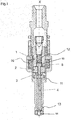
- Figure 1 shows a longitudinal section of an injector of the prior art, particularly, being suitable for dosing fuel to an internal combustion engine.
- the injector has a longitudinal axis X.
- the injector further comprises an injection valve housing 11 with an injection valve cavity.
- the injection valve cavity takes in a valve needle 5 being axially movable within the injection valve cavity relative to the injection valve housing 11.
- the valve needle 5 extends in axial direction X from a needle ball 14 at one axial end along a shaft 4 to an armature retainer 15 at an opposite axial end of the valve needle.
- the armature retainer 15 is in one piece with the shaft 4 and forms a collar at one end of the shaft.
- the armature retainer 15 can be a separate piece which is fixed to the shaft 4.
- the injector further comprises a valve seat 13, on which the needle ball 14 of the valve needle 5 rests in a closed position and from which the valve needle 5 is lifted for an open position.
- the closed position may also be denoted as closing position.
- the injector further comprises a spring element 12 being designed and arranged to exert a force on the valve needle 5 acting to urge the valve needle 5 in the closed position.
- the armature retainer acts as a spring seat for the spring element 12. In the closed position of the valve needle 5, the valve needle 5 sealingly rests on the valve seat 13, by this preventing fluid flow through at least one injection nozzle.
- the injection nozzle may be, for example, an injector hole. However, it may also be of some other type suitable for dosing fluid.
- the injector further comprises an electromagnetic actuator assembly, which is designed to actuate the valve needle 5.
- the electromagnetic actuator assembly comprises a coil, in particular a solenoid 10. It further comprises a pole piece 1 which is fixedly coupled to the injection valve housing 11.
- the electromagnetic actuator assembly further comprises an armature 2 which is axially movable within the injection valve cavity by an activation of the electromagnetic actuator assembly.
- the armature 2 is mechanically coupled or decoupled with the valve needle 5, preferably movable with respect thereto only within certain limits.
- the armature 2 can be positionally fix with respect to the valve needle 5 or axially displaceable with respect to the valve needle 5, as in the present embodiment.
- the valve needle 5 further comprises a stop element 3 which is welded on a shaft 4 of the valve needle 5.
- the stop element 3 is operable to limit axial displacement of the armature 2 relative to the valve needle in direction away from the pole piece 1.
- the injector preferably, applies a concept in which the armature momentum is used to generate an opening of the injector or the valve needle 5, i.e. a movement of the valve needle 5 towards the stop face 8 of the pole piece 1 ("kick" see below). During this movement, a hydraulic load on a valve seat 13 has to be overcome.
- valve needle 5 prevents a fluid flow through a fluid outlet portion and the injection valve housing 11 in the closed position of the valve needle 5. Outside of the closed position of the valve needle 5, the valve needle 5 enables the fluid flow through the fuel outlet portion.
- the electromagnetic actuator assembly may affect an electromagnetic force on the armature 2.
- the armature 2 is thus displaced towards the pole piece 1. For example it may move in a direction away from the fuel outlet portion, in particular upstream of a fluid flow, due to the electromagnetic force acting on the armature.
- the armature 2 may take the valve needle 5 with it, such that the valve needle 5 moves in axial direction out of the closed position.
- a gap between the injection valve housing 11 and the valve needle 5 at an axial end of the valve needle 5 facing away from the electromagnetic actuator assembly forms a fluid path and fluid can pass through the injection nozzle.
- the spring element 12 may force the valve needle 5 to move in axial direction in its closed position. It is dependent on the force balance between the forces on the valve needle 5 - including at least the force caused by the electromagnetic actuator assembly with the coil 10 and the force on the valve needle 5 caused by the spring element 12 - whether the valve needle 5 is in its closed position or not.
- the minimum injection of fluid, such as gasoline or diesel dispensed from the injector may relate at each injection pulse to the mass of 1.5 mg at pressures from e.g. 200 to 500 bar.
- Figure 2A shows a portion of a longitudinal section of an injector 100 according to the present disclosure.
- the injector corresponds in general to the injector described in connection with Figure 1 .
- the injector 100 of the present embodiment comprises a damping element 7 for damping of the movement of the valve needle during opening of the injector 100.
- the damping element 7 is axially fixed with respect to the pole piece 1.
- the damping element 7 is arranged axially between the stop face 8 of the pole piece 1 and the armature retainer 15 of the valve needle 5.
- the damping element 7 is further disposed at an inner surface 9 of the pole piece 1.
- the damping element 7 is arranged axially above, the valve needle 5, here at a position relative to the valve needle 5 facing axially away from the injector outlet or nozzle.
- the damping element 7 further abuts a stop face 8 of the pole piece 1 (cf. Figure 2A ).
- the pole piece 1 has a central recess 22,24 which is defined by the inner surface 9.
- the central recess 22,24 has a step 20 so that it is separated in a first portion 22 having a surface of the step 20 as a bottom surface and a second portion 24 upstream of the first portion 22.
- the bottom surface of the first portion represents the stop face 8.
- the second portion 24 has a smaller cross-sectional area than the first portion 22.
- the armature retainer 15 is arranged in the first portion 22 of the recess 22,24 of the pole piece 1 and axially guided by the first portion 22.
- the spring element 12 extends from a spring seat in the second portion to the armature retainer 15 in the first portion.
- the armature retainer 15 acts as a further spring seat for the spring element 12.
- FIG 2B shows a portion Y of the injector 100 which is indicated in Figure 2A in a magnified way.
- the valve needle 5 actually abuts the damping element 7.
- the damping element 7 may comprise a material which is adapted for a temperature range between -40 and +150 °C.
- the damping element 7 is preferably mounted to the injector 100 in a pre-compressed state, preferably the damping element 7 is pre-compressed by 1 to 2 N.
- the damping element 7 may be an O-ring.
- the spring element 12 extends through the central opening of the O-ring.
- the damping element 7 may comprise a viscoelastic material such as a rubber compound.
- the damping element 7 preferably, provides for a mass damping of the valve needle 5, when the valve needle 5 is moved towards the stop face 8 of the pole piece 1.
- the mass damping is provided for more than the final 20 ⁇ m of movement of the valve needle 5 towards the stop face 8 of the pole piece 1.
- opening of the injector 100 relates to a movement of the valve needle 5 upwards with respect to the pole piece 1.
- the injector 100 may further comprise a further damping arrangement which provides for a, e.g., hydraulic damping during movement of the valve needle away from the stop face 8 of the pole piece 1, i.e. during a closing of the injector.
- the damping arrangement may be represented mating surfaces of the armature 2 and the pole piece 1 which cooperate to provide hydraulic damping when the spring element 12 moves the valve needle towards the closed position - and, thus, the armature 2 out of contact with the pole piece 1 by means of mechanical interaction via the armature retainer 15.
- an additional damping arrangement may be provided for damping the movement of the armature 2 relative to the valve needle 5 when the armature 2 moves into contact with the stop element 3 of the valve needle 5.
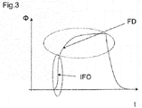
- Figure 3 shows a schematic course of a fluid flow ⁇ actually injected as a function of time t.
- the section of the course indicated by IFO relates to an initial fast opening of the injector, wherein the flow ⁇ of fluid strongly increases over time t.
- the section of the cause indicated by FD relates to a final damping regime in which, due to the herein described damping mechanism of the damping element 7, the flow increase is attenuated until the flow ⁇ is almost constant over time.
- the initial needle opening speed is relatively high which is important to achieve a good distribution of fuel during or after the injection. Due to the fact that the electromagnetic actuator assembly is active during the opening after the movement of the armature 2, the armature 2 is further accelerated during its movement in the injector valve housing 11, when the electromagnetic actuator assembly is active. For this reason it is not easy to control the position of the valve needle 5 with good accuracy e.g. by an electronic control unit in real time. Consequently, the mass flow of fluid and the achievement of very low fuel quantities poses problems especially in the ballistic operating range.
- the ballistic operating range may indicate the range in which the valve needle 5 is not in contact with the valve seat 13 and/or the stop face 8 of the pole piece 1.
- the mentioned problems may, particularly, overcome by the present invention, particularly by the provision of the mentioned damping element 7.
- the presented concept provides for a cost-efficient damping solution. Thereby, expensive damping solutions, such as dynamic pressure drop fixture, wherein slots or holes are provided in the armature, can be avoided.
- the armature 2 when the electromagnetic actuator assembly is activated or energized, the armature 2 is axially movable for an initial idle stroke until it contacts the armature retainer 15 of the valve needle 5 to generate the momentum and the above mentioned "kick" on the valve needle 5. Then, the armature 2 takes the valve needle 5 e.g. for about 80 to 90 ⁇ m with it on its travel towards the pole piece 1 (opening of the valve or so-called working stroke) such that the total movable distance of the armature 2 may relate to about 120 ⁇ m or 130 ⁇ m.
- the overall force F tot of the armature effected by the electromagnetic actuator assembly provides the momentum for the opening of the valve needle (cf. "kick" of the valve needle as described above).
Landscapes
- Engineering & Computer Science (AREA)
- Chemical & Material Sciences (AREA)
- Combustion & Propulsion (AREA)
- Mechanical Engineering (AREA)
- General Engineering & Computer Science (AREA)
- Physics & Mathematics (AREA)
- Electromagnetism (AREA)
- Fuel-Injection Apparatus (AREA)
Claims (12)
- Injecteur (100) pour un moteur à combustion, comprenant- un boîtier de soupape d'injection avec une cavité de soupape d'injection,- un pointeau de soupape (5) pouvant être déplacé axialement à l'intérieur de la cavité de soupape d'injection,- un ensemble d'actionneur électromagnétique comprenant un élément polaire (1) accouplé de manière fixe par rapport au boîtier de soupape d'injection dans la cavité de soupape d'injection et une armature (2) déplaçable axialement à l'intérieur de la cavité de soupape d'injection,- l'élément polaire (1) présentant un renfoncement central (22, 24) qui s'étend axialement à travers l'élément polaire (1) et qui présente un gradin (20) de manière à avoir une première portion (22) et une deuxième portion (24), la première portion (22) ayant une section transversale plus grande que la deuxième portion (24),- l'élément polaire (1) présentant une surface de butée (8) qui est une surface s'étendant radialement du gradin,- le pointeau de soupape (5) présente un élément de retenue d'armature (15) qui est positionné partiellement ou complètement dans la première portion (22) du renfoncement central de l'élément polaire (1),- l'armature (2) peut être déplacée axialement par rapport au pointeau de soupape (5) et peut être actionnée de manière à coopérer mécaniquement avec le pointeau de soupape (5) au moyen de l'élément de retenue d'armature (15) pour actionner le pointeau de soupape (5),- un élément d'amortissement (7) qui est agencé axialement entre la surface de butée (8) et l'élément de retenue d'armature (15) de manière à coopérer mécaniquement avec le pointeau de soupape (5) et l'élément polaire (1) pendant le déplacement du pointeau de soupape (5) par rapport à l'élément polaire (1).
- Injecteur (100) selon la revendication 1, dans lequel l'élément d'amortissement (7) est disposé à l'intérieur de la cavité de soupape d'injection, et dans lequel l'élément d'amortissement (7) est disposé de manière à buter contre la face de butée (8) de l'élément polaire (1).
- Injecteur (100) selon la revendication 2, dans lequel la face de butée (8) est disposée au niveau d'une surface interne (9) de l'élément polaire (1).
- Injecteur (100) selon l'une quelconque des revendications précédentes, dans lequel l'élément d'amortissement (7) est fixé axialement par rapport à l'élément polaire (1).
- Injecteur (100) selon l'une quelconque des revendications précédentes, dans lequel l'élément d'amortissement (7) est configuré de manière à fournir un amortissement de masse au cours du mouvement du pointeau de soupape (5) vers la face de butée (8) de l'élément polaire (1).
- Injecteur (100) selon la revendication 5, dans lequel l'amortissement de masse est prévu pour plus des derniers 20 µm de mouvement du pointeau de soupape (5) vers la face de butée (8) de l'élément polaire (1).
- Injecteur (100) selon la revendication 5 ou 6, dans lequel le mouvement du pointeau de soupape (5) vers la face de butée de l'élément polaire (1) se rapporte à une ouverture de l'injecteur (100).
- Injecteur (100) selon l'une quelconque des revendications précédentes, dans lequel l'ensemble d'actionneur électromagnétique est configuré de telle sorte qu'un mouvement de l'armature vers l'élément polaire à l'intérieur de la cavité de soupape d'injection soit transféré au pointeau de soupape (5) au cours d'une ouverture de l'injecteur (100).
- Injecteur (100) selon l'une quelconque des revendications précédentes, dans lequel l'élément d'amortissement (7) comprend un matériau viscoélastique tel qu'un composé de caoutchouc.
- Injecteur (100) selon l'une quelconque des revendications précédentes, dans lequel l'élément d'amortissement (7) est un joint torique.
- Injecteur (100) selon l'une quelconque des revendications précédentes, dans lequel l'élément d'amortissement (7) est monté sur l'injecteur (100) dans un état pré-comprimé.
- Injecteur (100) selon l'une quelconque des revendications précédentes, dans lequel le matériau de l'élément d'amortissement (7) est prévu pour une plage de température comprise entre - 40° C et + 150° C.
Priority Applications (1)
| Application Number | Priority Date | Filing Date | Title |
|---|---|---|---|
| EP14781583.1A EP3055552B1 (fr) | 2013-10-10 | 2014-10-09 | Injecteur pour moteur à combustion |
Applications Claiming Priority (3)
| Application Number | Priority Date | Filing Date | Title |
|---|---|---|---|
| EP20130187995 EP2860386A1 (fr) | 2013-10-10 | 2013-10-10 | Injecteur pour moteur à combustion |
| EP14781583.1A EP3055552B1 (fr) | 2013-10-10 | 2014-10-09 | Injecteur pour moteur à combustion |
| PCT/EP2014/071638 WO2015052281A1 (fr) | 2013-10-10 | 2014-10-09 | Injecteur pour un moteur à combustion |
Publications (2)
| Publication Number | Publication Date |
|---|---|
| EP3055552A1 EP3055552A1 (fr) | 2016-08-17 |
| EP3055552B1 true EP3055552B1 (fr) | 2017-07-26 |
Family
ID=49354472
Family Applications (2)
| Application Number | Title | Priority Date | Filing Date |
|---|---|---|---|
| EP20130187995 Withdrawn EP2860386A1 (fr) | 2013-10-10 | 2013-10-10 | Injecteur pour moteur à combustion |
| EP14781583.1A Not-in-force EP3055552B1 (fr) | 2013-10-10 | 2014-10-09 | Injecteur pour moteur à combustion |
Family Applications Before (1)
| Application Number | Title | Priority Date | Filing Date |
|---|---|---|---|
| EP20130187995 Withdrawn EP2860386A1 (fr) | 2013-10-10 | 2013-10-10 | Injecteur pour moteur à combustion |
Country Status (5)
| Country | Link |
|---|---|
| US (1) | US10202953B2 (fr) |
| EP (2) | EP2860386A1 (fr) |
| KR (1) | KR101947249B1 (fr) |
| CN (1) | CN105593508B (fr) |
| WO (1) | WO2015052281A1 (fr) |
Families Citing this family (8)
| Publication number | Priority date | Publication date | Assignee | Title |
|---|---|---|---|---|
| EP2860386A1 (fr) | 2013-10-10 | 2015-04-15 | Continental Automotive GmbH | Injecteur pour moteur à combustion |
| CN106134631B (zh) * | 2016-07-01 | 2018-01-30 | 冯青海 | 一种基于超磁致材料的收割装置 |
| EP3287632A1 (fr) | 2016-08-23 | 2018-02-28 | Continental Automotive GmbH | Ensemble de soupape pour soupape d'injection et soupape d'injection |
| EP3339626A1 (fr) | 2016-12-23 | 2018-06-27 | Continental Automotive GmbH | Ensemble de soupape comprenant une armature avec surfaces de guidage et passages d'écoulement et soupape d'injection |
| JP6708236B2 (ja) * | 2017-09-29 | 2020-06-10 | 株式会社デンソー | 燃料噴射弁 |
| JP6724959B2 (ja) * | 2017-09-29 | 2020-07-15 | 株式会社デンソー | 燃料噴射弁 |
| WO2019065412A1 (fr) * | 2017-09-29 | 2019-04-04 | 株式会社デンソー | Soupape d'injection de carburant |
| WO2019065414A1 (fr) * | 2017-09-29 | 2019-04-04 | 株式会社デンソー | Soupape d'injection de carburant |
Family Cites Families (30)
| Publication number | Priority date | Publication date | Assignee | Title |
|---|---|---|---|---|
| US1758105A (en) * | 1928-03-29 | 1930-05-13 | Louis O French | Electromagnetic valve |
| US4978074A (en) * | 1989-06-21 | 1990-12-18 | General Motors Corporation | Solenoid actuated valve assembly |
| JP2000291504A (ja) * | 1999-04-06 | 2000-10-17 | Mitsubishi Electric Corp | 燃料噴射弁 |
| DE19921489A1 (de) | 1999-05-08 | 2000-11-09 | Bosch Gmbh Robert | Brennstoffeinspritzventil |
| DE19946602A1 (de) * | 1999-09-29 | 2001-04-12 | Bosch Gmbh Robert | Brennstoffeinspritzventil |
| DE19948238A1 (de) * | 1999-10-07 | 2001-04-19 | Bosch Gmbh Robert | Brennstoffeinspritzventil |
| DE19950761A1 (de) * | 1999-10-21 | 2001-04-26 | Bosch Gmbh Robert | Brennstoffeinspritzventil |
| US6454191B1 (en) * | 2000-01-10 | 2002-09-24 | Delphi Technologies, Inc. | Electromagnetic fuel injector dampening device |
| DE10108974A1 (de) * | 2001-02-24 | 2002-09-05 | Bosch Gmbh Robert | Brennstoffeinspritzventil |
| DE10124747A1 (de) * | 2001-05-21 | 2002-11-28 | Bosch Gmbh Robert | Brennstoffeinspritzventil |
| DE10130205A1 (de) * | 2001-06-22 | 2003-01-02 | Bosch Gmbh Robert | Brennstoffeinspritzventil |
| DE10256661A1 (de) * | 2002-12-04 | 2004-06-17 | Robert Bosch Gmbh | Brennstoffeinspritzventil |
| DE102004037250B4 (de) * | 2004-07-31 | 2014-01-09 | Robert Bosch Gmbh | Brennstoffeinspritzventil |
| WO2006035656A1 (fr) * | 2004-09-27 | 2006-04-06 | Keihin Corporation | Valve d’injection de carburant a solenoide |
| JP4283255B2 (ja) * | 2005-08-04 | 2009-06-24 | 株式会社ケーヒン | ガス燃料用噴射弁 |
| JP2008031853A (ja) | 2006-07-26 | 2008-02-14 | Denso Corp | 燃料噴射弁 |
| DE102006049253A1 (de) * | 2006-10-19 | 2008-04-30 | Robert Bosch Gmbh | Brennstoffeinspritzventil |
| EP2112366B1 (fr) * | 2008-04-23 | 2011-11-02 | Magneti Marelli S.p.A. | Injecteur de carburant électromagnétique pour carburants gazeux avec dispositif d'arrêt anti-usure |
| EP2246554B1 (fr) | 2009-04-20 | 2012-06-27 | Continental Automotive GmbH | Ensemble de soupape pour soupape d'injection et soupape d'injection |
| JP5218487B2 (ja) * | 2009-12-04 | 2013-06-26 | 株式会社デンソー | 燃料噴射弁 |
| EP2336544A1 (fr) * | 2009-12-14 | 2011-06-22 | Delphi Technologies, Inc. | Mécanisme anti-retour pour injecteurs de carburant |
| EP2436910B1 (fr) * | 2010-10-01 | 2017-05-03 | Continental Automotive GmbH | Ensemble de soupape pour soupape d'injection et soupape d'injection |
| DE102010064105A1 (de) * | 2010-12-23 | 2012-01-19 | Robert Bosch Gmbh | Ventil zum Einspritzen von Kraftstoff |
| EP2527637B1 (fr) * | 2011-05-23 | 2014-10-08 | Continental Automotive GmbH | Injecteur pour injection de fluides |
| EP2535552B1 (fr) * | 2011-06-15 | 2015-02-25 | Continental Automotive GmbH | Ensemble de soupape pour soupape d'injection et soupape d'injection |
| DE102012203161A1 (de) * | 2012-02-29 | 2013-08-29 | Robert Bosch Gmbh | Einspritzventil |
| JP5955198B2 (ja) * | 2012-11-02 | 2016-07-20 | 株式会社ケーヒン | 直噴式燃料噴射弁の支持構造 |
| EP2796703B1 (fr) * | 2013-04-26 | 2016-07-20 | Continental Automotive GmbH | Ensemble de soupape pour soupape d'injection et soupape d'injection |
| EP2860386A1 (fr) | 2013-10-10 | 2015-04-15 | Continental Automotive GmbH | Injecteur pour moteur à combustion |
| EP2896813B1 (fr) * | 2014-01-17 | 2018-01-10 | Continental Automotive GmbH | Soupape d'injection de carburant pour moteurs à combustion interne |
-
2013
- 2013-10-10 EP EP20130187995 patent/EP2860386A1/fr not_active Withdrawn
-
2014
- 2014-10-09 US US15/028,119 patent/US10202953B2/en active Active
- 2014-10-09 CN CN201480055686.2A patent/CN105593508B/zh not_active Expired - Fee Related
- 2014-10-09 WO PCT/EP2014/071638 patent/WO2015052281A1/fr not_active Ceased
- 2014-10-09 EP EP14781583.1A patent/EP3055552B1/fr not_active Not-in-force
- 2014-10-09 KR KR1020167011569A patent/KR101947249B1/ko not_active Expired - Fee Related
Non-Patent Citations (1)
| Title |
|---|
| None * |
Also Published As
| Publication number | Publication date |
|---|---|
| CN105593508B (zh) | 2018-12-25 |
| WO2015052281A1 (fr) | 2015-04-16 |
| EP2860386A1 (fr) | 2015-04-15 |
| KR20160060761A (ko) | 2016-05-30 |
| CN105593508A (zh) | 2016-05-18 |
| US10202953B2 (en) | 2019-02-12 |
| KR101947249B1 (ko) | 2019-02-12 |
| EP3055552A1 (fr) | 2016-08-17 |
| US20160237966A1 (en) | 2016-08-18 |
Similar Documents
| Publication | Publication Date | Title |
|---|---|---|
| EP3055552B1 (fr) | Injecteur pour moteur à combustion | |
| EP2336544A1 (fr) | Mécanisme anti-retour pour injecteurs de carburant | |
| CN103890370B (zh) | 用于喷射阀的阀组件和喷射阀 | |
| EP2535552B1 (fr) | Ensemble de soupape pour soupape d'injection et soupape d'injection | |
| EP2436910B1 (fr) | Ensemble de soupape pour soupape d'injection et soupape d'injection | |
| CN104912706B (zh) | 燃料喷射器 | |
| US7156368B2 (en) | Solenoid actuated flow controller valve | |
| EP2796703B1 (fr) | Ensemble de soupape pour soupape d'injection et soupape d'injection | |
| EP1783356B1 (fr) | Soupape d'injection de carburant | |
| EP2527637A1 (fr) | Injecteur pour injection de fluides | |
| KR102119988B1 (ko) | 튀어오름 방지 디바이스를 구비한 연료 분사 밸브, 연소 기관 및 차량 | |
| EP2597296B1 (fr) | Ensemble de soupape pour soupape d'injection et soupape d'injection | |
| EP2851551B1 (fr) | Soupape d'injection de fluide | |
| EP3267026B1 (fr) | Ensemble de soupape pour soupape d'injection et soupape d'injection | |
| KR102139895B1 (ko) | 자기 링 요소를 갖는 분사 밸브 | |
| EP2365205B1 (fr) | Soupape d'injection | |
| CN106930881A (zh) | 用于计量流体的阀 | |
| EP2166220B1 (fr) | Soupape d'injection | |
| US20190211786A1 (en) | Valve Assembly for an Injection Valve and Injection Valve | |
| EP3611368A1 (fr) | Ensemble de soupape et soupape d'injection de carburant | |
| EP2863044B1 (fr) | Soupape d'injection |
Legal Events
| Date | Code | Title | Description |
|---|---|---|---|
| PUAI | Public reference made under article 153(3) epc to a published international application that has entered the european phase |
Free format text: ORIGINAL CODE: 0009012 |
|
| 17P | Request for examination filed |
Effective date: 20160510 |
|
| AK | Designated contracting states |
Kind code of ref document: A1 Designated state(s): AL AT BE BG CH CY CZ DE DK EE ES FI FR GB GR HR HU IE IS IT LI LT LU LV MC MK MT NL NO PL PT RO RS SE SI SK SM TR |
|
| AX | Request for extension of the european patent |
Extension state: BA ME |
|
| DAX | Request for extension of the european patent (deleted) | ||
| REG | Reference to a national code |
Ref country code: DE Ref legal event code: R079 Ref document number: 602014012350 Country of ref document: DE Free format text: PREVIOUS MAIN CLASS: F02M0051060000 Ipc: F02M0061200000 |
|
| RIC1 | Information provided on ipc code assigned before grant |
Ipc: F02M 51/06 20060101ALI20170125BHEP Ipc: F02M 61/20 20060101AFI20170125BHEP |
|
| GRAP | Despatch of communication of intention to grant a patent |
Free format text: ORIGINAL CODE: EPIDOSNIGR1 |
|
| INTG | Intention to grant announced |
Effective date: 20170303 |
|
| GRAS | Grant fee paid |
Free format text: ORIGINAL CODE: EPIDOSNIGR3 |
|
| GRAA | (expected) grant |
Free format text: ORIGINAL CODE: 0009210 |
|
| AK | Designated contracting states |
Kind code of ref document: B1 Designated state(s): AL AT BE BG CH CY CZ DE DK EE ES FI FR GB GR HR HU IE IS IT LI LT LU LV MC MK MT NL NO PL PT RO RS SE SI SK SM TR |
|
| REG | Reference to a national code |
Ref country code: GB Ref legal event code: FG4D |
|
| REG | Reference to a national code |
Ref country code: CH Ref legal event code: EP |
|
| REG | Reference to a national code |
Ref country code: AT Ref legal event code: REF Ref document number: 912630 Country of ref document: AT Kind code of ref document: T Effective date: 20170815 |
|
| REG | Reference to a national code |
Ref country code: IE Ref legal event code: FG4D |
|
| REG | Reference to a national code |
Ref country code: DE Ref legal event code: R096 Ref document number: 602014012350 Country of ref document: DE |
|
| REG | Reference to a national code |
Ref country code: FR Ref legal event code: PLFP Year of fee payment: 4 |
|
| REG | Reference to a national code |
Ref country code: NL Ref legal event code: MP Effective date: 20170726 |
|
| REG | Reference to a national code |
Ref country code: LT Ref legal event code: MG4D |
|
| REG | Reference to a national code |
Ref country code: AT Ref legal event code: MK05 Ref document number: 912630 Country of ref document: AT Kind code of ref document: T Effective date: 20170726 |
|
| PG25 | Lapsed in a contracting state [announced via postgrant information from national office to epo] |
Ref country code: FI Free format text: LAPSE BECAUSE OF FAILURE TO SUBMIT A TRANSLATION OF THE DESCRIPTION OR TO PAY THE FEE WITHIN THE PRESCRIBED TIME-LIMIT Effective date: 20170726 Ref country code: LT Free format text: LAPSE BECAUSE OF FAILURE TO SUBMIT A TRANSLATION OF THE DESCRIPTION OR TO PAY THE FEE WITHIN THE PRESCRIBED TIME-LIMIT Effective date: 20170726 Ref country code: NL Free format text: LAPSE BECAUSE OF FAILURE TO SUBMIT A TRANSLATION OF THE DESCRIPTION OR TO PAY THE FEE WITHIN THE PRESCRIBED TIME-LIMIT Effective date: 20170726 Ref country code: NO Free format text: LAPSE BECAUSE OF FAILURE TO SUBMIT A TRANSLATION OF THE DESCRIPTION OR TO PAY THE FEE WITHIN THE PRESCRIBED TIME-LIMIT Effective date: 20171026 Ref country code: AT Free format text: LAPSE BECAUSE OF FAILURE TO SUBMIT A TRANSLATION OF THE DESCRIPTION OR TO PAY THE FEE WITHIN THE PRESCRIBED TIME-LIMIT Effective date: 20170726 Ref country code: SE Free format text: LAPSE BECAUSE OF FAILURE TO SUBMIT A TRANSLATION OF THE DESCRIPTION OR TO PAY THE FEE WITHIN THE PRESCRIBED TIME-LIMIT Effective date: 20170726 Ref country code: HR Free format text: LAPSE BECAUSE OF FAILURE TO SUBMIT A TRANSLATION OF THE DESCRIPTION OR TO PAY THE FEE WITHIN THE PRESCRIBED TIME-LIMIT Effective date: 20170726 |
|
| PG25 | Lapsed in a contracting state [announced via postgrant information from national office to epo] |
Ref country code: RS Free format text: LAPSE BECAUSE OF FAILURE TO SUBMIT A TRANSLATION OF THE DESCRIPTION OR TO PAY THE FEE WITHIN THE PRESCRIBED TIME-LIMIT Effective date: 20170726 Ref country code: IS Free format text: LAPSE BECAUSE OF FAILURE TO SUBMIT A TRANSLATION OF THE DESCRIPTION OR TO PAY THE FEE WITHIN THE PRESCRIBED TIME-LIMIT Effective date: 20171126 Ref country code: GR Free format text: LAPSE BECAUSE OF FAILURE TO SUBMIT A TRANSLATION OF THE DESCRIPTION OR TO PAY THE FEE WITHIN THE PRESCRIBED TIME-LIMIT Effective date: 20171027 Ref country code: ES Free format text: LAPSE BECAUSE OF FAILURE TO SUBMIT A TRANSLATION OF THE DESCRIPTION OR TO PAY THE FEE WITHIN THE PRESCRIBED TIME-LIMIT Effective date: 20170726 Ref country code: PL Free format text: LAPSE BECAUSE OF FAILURE TO SUBMIT A TRANSLATION OF THE DESCRIPTION OR TO PAY THE FEE WITHIN THE PRESCRIBED TIME-LIMIT Effective date: 20170726 Ref country code: BG Free format text: LAPSE BECAUSE OF FAILURE TO SUBMIT A TRANSLATION OF THE DESCRIPTION OR TO PAY THE FEE WITHIN THE PRESCRIBED TIME-LIMIT Effective date: 20171026 Ref country code: LV Free format text: LAPSE BECAUSE OF FAILURE TO SUBMIT A TRANSLATION OF THE DESCRIPTION OR TO PAY THE FEE WITHIN THE PRESCRIBED TIME-LIMIT Effective date: 20170726 |
|
| PG25 | Lapsed in a contracting state [announced via postgrant information from national office to epo] |
Ref country code: CZ Free format text: LAPSE BECAUSE OF FAILURE TO SUBMIT A TRANSLATION OF THE DESCRIPTION OR TO PAY THE FEE WITHIN THE PRESCRIBED TIME-LIMIT Effective date: 20170726 Ref country code: DK Free format text: LAPSE BECAUSE OF FAILURE TO SUBMIT A TRANSLATION OF THE DESCRIPTION OR TO PAY THE FEE WITHIN THE PRESCRIBED TIME-LIMIT Effective date: 20170726 Ref country code: RO Free format text: LAPSE BECAUSE OF FAILURE TO SUBMIT A TRANSLATION OF THE DESCRIPTION OR TO PAY THE FEE WITHIN THE PRESCRIBED TIME-LIMIT Effective date: 20170726 |
|
| REG | Reference to a national code |
Ref country code: DE Ref legal event code: R097 Ref document number: 602014012350 Country of ref document: DE |
|
| PG25 | Lapsed in a contracting state [announced via postgrant information from national office to epo] |
Ref country code: SM Free format text: LAPSE BECAUSE OF FAILURE TO SUBMIT A TRANSLATION OF THE DESCRIPTION OR TO PAY THE FEE WITHIN THE PRESCRIBED TIME-LIMIT Effective date: 20170726 Ref country code: EE Free format text: LAPSE BECAUSE OF FAILURE TO SUBMIT A TRANSLATION OF THE DESCRIPTION OR TO PAY THE FEE WITHIN THE PRESCRIBED TIME-LIMIT Effective date: 20170726 Ref country code: SK Free format text: LAPSE BECAUSE OF FAILURE TO SUBMIT A TRANSLATION OF THE DESCRIPTION OR TO PAY THE FEE WITHIN THE PRESCRIBED TIME-LIMIT Effective date: 20170726 Ref country code: MC Free format text: LAPSE BECAUSE OF FAILURE TO SUBMIT A TRANSLATION OF THE DESCRIPTION OR TO PAY THE FEE WITHIN THE PRESCRIBED TIME-LIMIT Effective date: 20170726 |
|
| REG | Reference to a national code |
Ref country code: CH Ref legal event code: PL |
|
| PLBE | No opposition filed within time limit |
Free format text: ORIGINAL CODE: 0009261 |
|
| STAA | Information on the status of an ep patent application or granted ep patent |
Free format text: STATUS: NO OPPOSITION FILED WITHIN TIME LIMIT |
|
| 26N | No opposition filed |
Effective date: 20180430 |
|
| REG | Reference to a national code |
Ref country code: IE Ref legal event code: MM4A |
|
| PG25 | Lapsed in a contracting state [announced via postgrant information from national office to epo] |
Ref country code: CH Free format text: LAPSE BECAUSE OF NON-PAYMENT OF DUE FEES Effective date: 20171031 Ref country code: LU Free format text: LAPSE BECAUSE OF NON-PAYMENT OF DUE FEES Effective date: 20171009 Ref country code: LI Free format text: LAPSE BECAUSE OF NON-PAYMENT OF DUE FEES Effective date: 20171031 |
|
| REG | Reference to a national code |
Ref country code: BE Ref legal event code: MM Effective date: 20171031 |
|
| PG25 | Lapsed in a contracting state [announced via postgrant information from national office to epo] |
Ref country code: SI Free format text: LAPSE BECAUSE OF FAILURE TO SUBMIT A TRANSLATION OF THE DESCRIPTION OR TO PAY THE FEE WITHIN THE PRESCRIBED TIME-LIMIT Effective date: 20170726 Ref country code: BE Free format text: LAPSE BECAUSE OF NON-PAYMENT OF DUE FEES Effective date: 20171031 |
|
| PG25 | Lapsed in a contracting state [announced via postgrant information from national office to epo] |
Ref country code: MT Free format text: LAPSE BECAUSE OF NON-PAYMENT OF DUE FEES Effective date: 20171009 |
|
| REG | Reference to a national code |
Ref country code: FR Ref legal event code: PLFP Year of fee payment: 5 |
|
| PG25 | Lapsed in a contracting state [announced via postgrant information from national office to epo] |
Ref country code: IE Free format text: LAPSE BECAUSE OF NON-PAYMENT OF DUE FEES Effective date: 20171009 |
|
| PG25 | Lapsed in a contracting state [announced via postgrant information from national office to epo] |
Ref country code: HU Free format text: LAPSE BECAUSE OF FAILURE TO SUBMIT A TRANSLATION OF THE DESCRIPTION OR TO PAY THE FEE WITHIN THE PRESCRIBED TIME-LIMIT; INVALID AB INITIO Effective date: 20141009 |
|
| PG25 | Lapsed in a contracting state [announced via postgrant information from national office to epo] |
Ref country code: CY Free format text: LAPSE BECAUSE OF FAILURE TO SUBMIT A TRANSLATION OF THE DESCRIPTION OR TO PAY THE FEE WITHIN THE PRESCRIBED TIME-LIMIT Effective date: 20170726 |
|
| PG25 | Lapsed in a contracting state [announced via postgrant information from national office to epo] |
Ref country code: MK Free format text: LAPSE BECAUSE OF FAILURE TO SUBMIT A TRANSLATION OF THE DESCRIPTION OR TO PAY THE FEE WITHIN THE PRESCRIBED TIME-LIMIT Effective date: 20170726 |
|
| PG25 | Lapsed in a contracting state [announced via postgrant information from national office to epo] |
Ref country code: TR Free format text: LAPSE BECAUSE OF FAILURE TO SUBMIT A TRANSLATION OF THE DESCRIPTION OR TO PAY THE FEE WITHIN THE PRESCRIBED TIME-LIMIT Effective date: 20170726 |
|
| PG25 | Lapsed in a contracting state [announced via postgrant information from national office to epo] |
Ref country code: PT Free format text: LAPSE BECAUSE OF FAILURE TO SUBMIT A TRANSLATION OF THE DESCRIPTION OR TO PAY THE FEE WITHIN THE PRESCRIBED TIME-LIMIT Effective date: 20170726 |
|
| REG | Reference to a national code |
Ref country code: DE Ref legal event code: R081 Ref document number: 602014012350 Country of ref document: DE Owner name: VITESCO TECHNOLOGIES GMBH, DE Free format text: FORMER OWNER: CONTINENTAL AUTOMOTIVE GMBH, 30165 HANNOVER, DE |
|
| PG25 | Lapsed in a contracting state [announced via postgrant information from national office to epo] |
Ref country code: AL Free format text: LAPSE BECAUSE OF FAILURE TO SUBMIT A TRANSLATION OF THE DESCRIPTION OR TO PAY THE FEE WITHIN THE PRESCRIBED TIME-LIMIT Effective date: 20170726 |
|
| REG | Reference to a national code |
Ref country code: DE Ref legal event code: R081 Ref document number: 602014012350 Country of ref document: DE Owner name: VITESCO TECHNOLOGIES GMBH, DE Free format text: FORMER OWNER: VITESCO TECHNOLOGIES GMBH, 30165 HANNOVER, DE |
|
| REG | Reference to a national code |
Ref country code: GB Ref legal event code: 732E Free format text: REGISTERED BETWEEN 20230427 AND 20230503 |
|
| P01 | Opt-out of the competence of the unified patent court (upc) registered |
Effective date: 20230530 |
|
| PGFP | Annual fee paid to national office [announced via postgrant information from national office to epo] |
Ref country code: GB Payment date: 20231020 Year of fee payment: 10 |
|
| PGFP | Annual fee paid to national office [announced via postgrant information from national office to epo] |
Ref country code: IT Payment date: 20231026 Year of fee payment: 10 Ref country code: FR Payment date: 20231026 Year of fee payment: 10 Ref country code: DE Payment date: 20231031 Year of fee payment: 10 |
|
| REG | Reference to a national code |
Ref country code: DE Ref legal event code: R119 Ref document number: 602014012350 Country of ref document: DE |
|
| GBPC | Gb: european patent ceased through non-payment of renewal fee |
Effective date: 20241009 |
|
| PG25 | Lapsed in a contracting state [announced via postgrant information from national office to epo] |
Ref country code: DE Free format text: LAPSE BECAUSE OF NON-PAYMENT OF DUE FEES Effective date: 20250501 |
|
| PG25 | Lapsed in a contracting state [announced via postgrant information from national office to epo] |
Ref country code: GB Free format text: LAPSE BECAUSE OF NON-PAYMENT OF DUE FEES Effective date: 20241009 |
|
| PG25 | Lapsed in a contracting state [announced via postgrant information from national office to epo] |
Ref country code: FR Free format text: LAPSE BECAUSE OF NON-PAYMENT OF DUE FEES Effective date: 20241031 |
|
| PG25 | Lapsed in a contracting state [announced via postgrant information from national office to epo] |
Ref country code: IT Free format text: LAPSE BECAUSE OF NON-PAYMENT OF DUE FEES Effective date: 20241009 |