EP3055441B1 - Vorrichtung und verfahren zur beschichtung eines werkstücks mittels kathodischer lichtbogenverdampfung - Google Patents
Vorrichtung und verfahren zur beschichtung eines werkstücks mittels kathodischer lichtbogenverdampfung Download PDFInfo
- Publication number
- EP3055441B1 EP3055441B1 EP14852888.8A EP14852888A EP3055441B1 EP 3055441 B1 EP3055441 B1 EP 3055441B1 EP 14852888 A EP14852888 A EP 14852888A EP 3055441 B1 EP3055441 B1 EP 3055441B1
- Authority
- EP
- European Patent Office
- Prior art keywords
- cathode
- cup
- workpiece
- stinger
- electrically conductive
- Prior art date
- Legal status (The legal status is an assumption and is not a legal conclusion. Google has not performed a legal analysis and makes no representation as to the accuracy of the status listed.)
- Active
Links
Images

Classifications
-
- H—ELECTRICITY
- H01—ELECTRIC ELEMENTS
- H01J—ELECTRIC DISCHARGE TUBES OR DISCHARGE LAMPS
- H01J37/00—Discharge tubes with provision for introducing objects or material to be exposed to the discharge, e.g. for the purpose of examination or processing thereof
- H01J37/32—Gas-filled discharge tubes
- H01J37/32431—Constructional details of the reactor
- H01J37/3266—Magnetic control means
-
- C—CHEMISTRY; METALLURGY
- C23—COATING METALLIC MATERIAL; COATING MATERIAL WITH METALLIC MATERIAL; CHEMICAL SURFACE TREATMENT; DIFFUSION TREATMENT OF METALLIC MATERIAL; COATING BY VACUUM EVAPORATION, BY SPUTTERING, BY ION IMPLANTATION OR BY CHEMICAL VAPOUR DEPOSITION, IN GENERAL; INHIBITING CORROSION OF METALLIC MATERIAL OR INCRUSTATION IN GENERAL
- C23C—COATING METALLIC MATERIAL; COATING MATERIAL WITH METALLIC MATERIAL; SURFACE TREATMENT OF METALLIC MATERIAL BY DIFFUSION INTO THE SURFACE, BY CHEMICAL CONVERSION OR SUBSTITUTION; COATING BY VACUUM EVAPORATION, BY SPUTTERING, BY ION IMPLANTATION OR BY CHEMICAL VAPOUR DEPOSITION, IN GENERAL
- C23C14/00—Coating by vacuum evaporation, by sputtering or by ion implantation of the coating forming material
- C23C14/06—Coating by vacuum evaporation, by sputtering or by ion implantation of the coating forming material characterised by the coating material
- C23C14/0635—Carbides
-
- C—CHEMISTRY; METALLURGY
- C23—COATING METALLIC MATERIAL; COATING MATERIAL WITH METALLIC MATERIAL; CHEMICAL SURFACE TREATMENT; DIFFUSION TREATMENT OF METALLIC MATERIAL; COATING BY VACUUM EVAPORATION, BY SPUTTERING, BY ION IMPLANTATION OR BY CHEMICAL VAPOUR DEPOSITION, IN GENERAL; INHIBITING CORROSION OF METALLIC MATERIAL OR INCRUSTATION IN GENERAL
- C23C—COATING METALLIC MATERIAL; COATING MATERIAL WITH METALLIC MATERIAL; SURFACE TREATMENT OF METALLIC MATERIAL BY DIFFUSION INTO THE SURFACE, BY CHEMICAL CONVERSION OR SUBSTITUTION; COATING BY VACUUM EVAPORATION, BY SPUTTERING, BY ION IMPLANTATION OR BY CHEMICAL VAPOUR DEPOSITION, IN GENERAL
- C23C14/00—Coating by vacuum evaporation, by sputtering or by ion implantation of the coating forming material
- C23C14/06—Coating by vacuum evaporation, by sputtering or by ion implantation of the coating forming material characterised by the coating material
- C23C14/0641—Nitrides
-
- C—CHEMISTRY; METALLURGY
- C23—COATING METALLIC MATERIAL; COATING MATERIAL WITH METALLIC MATERIAL; CHEMICAL SURFACE TREATMENT; DIFFUSION TREATMENT OF METALLIC MATERIAL; COATING BY VACUUM EVAPORATION, BY SPUTTERING, BY ION IMPLANTATION OR BY CHEMICAL VAPOUR DEPOSITION, IN GENERAL; INHIBITING CORROSION OF METALLIC MATERIAL OR INCRUSTATION IN GENERAL
- C23C—COATING METALLIC MATERIAL; COATING MATERIAL WITH METALLIC MATERIAL; SURFACE TREATMENT OF METALLIC MATERIAL BY DIFFUSION INTO THE SURFACE, BY CHEMICAL CONVERSION OR SUBSTITUTION; COATING BY VACUUM EVAPORATION, BY SPUTTERING, BY ION IMPLANTATION OR BY CHEMICAL VAPOUR DEPOSITION, IN GENERAL
- C23C14/00—Coating by vacuum evaporation, by sputtering or by ion implantation of the coating forming material
- C23C14/06—Coating by vacuum evaporation, by sputtering or by ion implantation of the coating forming material characterised by the coating material
- C23C14/0664—Carbonitrides
-
- C—CHEMISTRY; METALLURGY
- C23—COATING METALLIC MATERIAL; COATING MATERIAL WITH METALLIC MATERIAL; CHEMICAL SURFACE TREATMENT; DIFFUSION TREATMENT OF METALLIC MATERIAL; COATING BY VACUUM EVAPORATION, BY SPUTTERING, BY ION IMPLANTATION OR BY CHEMICAL VAPOUR DEPOSITION, IN GENERAL; INHIBITING CORROSION OF METALLIC MATERIAL OR INCRUSTATION IN GENERAL
- C23C—COATING METALLIC MATERIAL; COATING MATERIAL WITH METALLIC MATERIAL; SURFACE TREATMENT OF METALLIC MATERIAL BY DIFFUSION INTO THE SURFACE, BY CHEMICAL CONVERSION OR SUBSTITUTION; COATING BY VACUUM EVAPORATION, BY SPUTTERING, BY ION IMPLANTATION OR BY CHEMICAL VAPOUR DEPOSITION, IN GENERAL
- C23C14/00—Coating by vacuum evaporation, by sputtering or by ion implantation of the coating forming material
- C23C14/06—Coating by vacuum evaporation, by sputtering or by ion implantation of the coating forming material characterised by the coating material
- C23C14/08—Oxides
- C23C14/081—Oxides of aluminium, magnesium or beryllium
-
- C—CHEMISTRY; METALLURGY
- C23—COATING METALLIC MATERIAL; COATING MATERIAL WITH METALLIC MATERIAL; CHEMICAL SURFACE TREATMENT; DIFFUSION TREATMENT OF METALLIC MATERIAL; COATING BY VACUUM EVAPORATION, BY SPUTTERING, BY ION IMPLANTATION OR BY CHEMICAL VAPOUR DEPOSITION, IN GENERAL; INHIBITING CORROSION OF METALLIC MATERIAL OR INCRUSTATION IN GENERAL
- C23C—COATING METALLIC MATERIAL; COATING MATERIAL WITH METALLIC MATERIAL; SURFACE TREATMENT OF METALLIC MATERIAL BY DIFFUSION INTO THE SURFACE, BY CHEMICAL CONVERSION OR SUBSTITUTION; COATING BY VACUUM EVAPORATION, BY SPUTTERING, BY ION IMPLANTATION OR BY CHEMICAL VAPOUR DEPOSITION, IN GENERAL
- C23C14/00—Coating by vacuum evaporation, by sputtering or by ion implantation of the coating forming material
- C23C14/06—Coating by vacuum evaporation, by sputtering or by ion implantation of the coating forming material characterised by the coating material
- C23C14/08—Oxides
- C23C14/083—Oxides of refractory metals or yttrium
-
- C—CHEMISTRY; METALLURGY
- C23—COATING METALLIC MATERIAL; COATING MATERIAL WITH METALLIC MATERIAL; CHEMICAL SURFACE TREATMENT; DIFFUSION TREATMENT OF METALLIC MATERIAL; COATING BY VACUUM EVAPORATION, BY SPUTTERING, BY ION IMPLANTATION OR BY CHEMICAL VAPOUR DEPOSITION, IN GENERAL; INHIBITING CORROSION OF METALLIC MATERIAL OR INCRUSTATION IN GENERAL
- C23C—COATING METALLIC MATERIAL; COATING MATERIAL WITH METALLIC MATERIAL; SURFACE TREATMENT OF METALLIC MATERIAL BY DIFFUSION INTO THE SURFACE, BY CHEMICAL CONVERSION OR SUBSTITUTION; COATING BY VACUUM EVAPORATION, BY SPUTTERING, BY ION IMPLANTATION OR BY CHEMICAL VAPOUR DEPOSITION, IN GENERAL
- C23C14/00—Coating by vacuum evaporation, by sputtering or by ion implantation of the coating forming material
- C23C14/06—Coating by vacuum evaporation, by sputtering or by ion implantation of the coating forming material characterised by the coating material
- C23C14/14—Metallic material, boron or silicon
-
- C—CHEMISTRY; METALLURGY
- C23—COATING METALLIC MATERIAL; COATING MATERIAL WITH METALLIC MATERIAL; CHEMICAL SURFACE TREATMENT; DIFFUSION TREATMENT OF METALLIC MATERIAL; COATING BY VACUUM EVAPORATION, BY SPUTTERING, BY ION IMPLANTATION OR BY CHEMICAL VAPOUR DEPOSITION, IN GENERAL; INHIBITING CORROSION OF METALLIC MATERIAL OR INCRUSTATION IN GENERAL
- C23C—COATING METALLIC MATERIAL; COATING MATERIAL WITH METALLIC MATERIAL; SURFACE TREATMENT OF METALLIC MATERIAL BY DIFFUSION INTO THE SURFACE, BY CHEMICAL CONVERSION OR SUBSTITUTION; COATING BY VACUUM EVAPORATION, BY SPUTTERING, BY ION IMPLANTATION OR BY CHEMICAL VAPOUR DEPOSITION, IN GENERAL
- C23C14/00—Coating by vacuum evaporation, by sputtering or by ion implantation of the coating forming material
- C23C14/22—Coating by vacuum evaporation, by sputtering or by ion implantation of the coating forming material characterised by the process of coating
- C23C14/24—Vacuum evaporation
- C23C14/32—Vacuum evaporation by explosion; by evaporation and subsequent ionisation of the vapours, e.g. ion-plating
- C23C14/325—Electric arc evaporation
-
- H—ELECTRICITY
- H01—ELECTRIC ELEMENTS
- H01J—ELECTRIC DISCHARGE TUBES OR DISCHARGE LAMPS
- H01J37/00—Discharge tubes with provision for introducing objects or material to be exposed to the discharge, e.g. for the purpose of examination or processing thereof
- H01J37/32—Gas-filled discharge tubes
- H01J37/32009—Arrangements for generation of plasma specially adapted for examination or treatment of objects, e.g. plasma sources
- H01J37/32055—Arc discharge
-
- H—ELECTRICITY
- H01—ELECTRIC ELEMENTS
- H01J—ELECTRIC DISCHARGE TUBES OR DISCHARGE LAMPS
- H01J37/00—Discharge tubes with provision for introducing objects or material to be exposed to the discharge, e.g. for the purpose of examination or processing thereof
- H01J37/32—Gas-filled discharge tubes
- H01J37/32431—Constructional details of the reactor
- H01J37/32458—Vessel
- H01J37/32522—Temperature
-
- H—ELECTRICITY
- H01—ELECTRIC ELEMENTS
- H01J—ELECTRIC DISCHARGE TUBES OR DISCHARGE LAMPS
- H01J37/00—Discharge tubes with provision for introducing objects or material to be exposed to the discharge, e.g. for the purpose of examination or processing thereof
- H01J37/32—Gas-filled discharge tubes
- H01J37/32431—Constructional details of the reactor
- H01J37/32532—Electrodes
- H01J37/32614—Consumable cathodes for arc discharge
-
- H—ELECTRICITY
- H01—ELECTRIC ELEMENTS
- H01J—ELECTRIC DISCHARGE TUBES OR DISCHARGE LAMPS
- H01J37/00—Discharge tubes with provision for introducing objects or material to be exposed to the discharge, e.g. for the purpose of examination or processing thereof
- H01J37/32—Gas-filled discharge tubes
- H01J37/32431—Constructional details of the reactor
- H01J37/3266—Magnetic control means
- H01J37/32669—Particular magnets or magnet arrangements for controlling the discharge
-
- H—ELECTRICITY
- H01—ELECTRIC ELEMENTS
- H01J—ELECTRIC DISCHARGE TUBES OR DISCHARGE LAMPS
- H01J37/00—Discharge tubes with provision for introducing objects or material to be exposed to the discharge, e.g. for the purpose of examination or processing thereof
- H01J37/32—Gas-filled discharge tubes
- H01J37/32431—Constructional details of the reactor
- H01J37/32798—Further details of plasma apparatus not provided for in groups H01J37/3244 - H01J37/32788; special provisions for cleaning or maintenance of the apparatus
- H01J37/32816—Pressure
-
- H—ELECTRICITY
- H01—ELECTRIC ELEMENTS
- H01J—ELECTRIC DISCHARGE TUBES OR DISCHARGE LAMPS
- H01J2237/00—Discharge tubes exposing object to beam, e.g. for analysis treatment, etching, imaging
- H01J2237/32—Processing objects by plasma generation
- H01J2237/327—Arrangements for generating the plasma
-
- H—ELECTRICITY
- H01—ELECTRIC ELEMENTS
- H01J—ELECTRIC DISCHARGE TUBES OR DISCHARGE LAMPS
- H01J2237/00—Discharge tubes exposing object to beam, e.g. for analysis treatment, etching, imaging
- H01J2237/32—Processing objects by plasma generation
- H01J2237/33—Processing objects by plasma generation characterised by the type of processing
- H01J2237/332—Coating
-
- H—ELECTRICITY
- H01—ELECTRIC ELEMENTS
- H01J—ELECTRIC DISCHARGE TUBES OR DISCHARGE LAMPS
- H01J37/00—Discharge tubes with provision for introducing objects or material to be exposed to the discharge, e.g. for the purpose of examination or processing thereof
- H01J37/32—Gas-filled discharge tubes
- H01J37/34—Gas-filled discharge tubes operating with cathodic sputtering
- H01J37/3411—Constructional aspects of the reactor
- H01J37/3435—Target holders (includes backing plates and endblocks)
Definitions
- the disclosed subject matter relates generally to vapor deposition and more particularly to cathodic arc vapor deposition.
- Cathodic arc vapor deposition typically involves placing one or more workpieces in an evacuated deposition chamber or vessel along with one or more blocks of coating material.
- An electrical arc is initiated, for example by a trigger, which first contacts the coating material serving as a cathode. As the trigger is moved away from the cathode, the arc jumps between the coating material and an anode, which may be for example, an inside surface of the vessel. The arc vaporizes the cathodic coating material into a plasma, which contains positively charged ions that are attracted toward workpieces to be coated.
- Cathodic arc coaters can use water or an aqueous solution to directly or indirectly cool the cathode.
- coolant is provided to directly cool a stinger used to the steer the arc. Cooling the stinger indirectly cools the cathode primarily by conduction.
- high cathode temperatures can cause thermal stress cracking of the cathode due to limitations of the coolant.
- Higher boiling-point coolants such as glycol can reduce the thermal gradient but increase the risk that the magnets are heated above their Curie temperature, causing loss of magnetic arc steering control.
- US 6036828 describes an apparatus for steering the arc in a cathodic arc coater.
- EP 2276053 A1 describes a target backing tube for a cylindrical target assembly and sputtering system.
- EP 0899773 A2 describes an apparatus for driving an arc in a cathodic arc coater.
- a cathodic arc coating apparatus is defined in claim 1.
- a method for coating a workpiece is defined in claim 10.
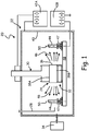
- FIG. 1 is a schematic view of cathodic arc coating apparatus 20, which includes vessel 22, cathode 24, trigger 28, stinger assembly 30, and base 32.
- Vessel 22 can be a sealed housing or similar construction able to maintain a vacuum during the coating process with the assistance of one or more vacuum pumps 34.
- Cathode 24, which can be disposed in one or more locations of vessel 22, has at least one evaporative surface.
- cathode 24 can be a puck with evaporative surface 36 extending between first end surface 38A and second end surface 38B.
- One or more pucks operable as cathode 24 can be formed of a metallic material used in the cathodic arc coating process, such as nickel, cobalt, chromium, aluminum, titanium, yttrium, zirconium, and alloys thereof. Additional or alternative configurations of cathode 24 are also possible, and include toroids, cylinders (both hollow and solid), among others. One or more cathodes 24 can additionally or alternatively be used to form a composite coating.
- Trigger 28 is adapted to selectively initiate an arc between cathode 24 and one or more anodes such as inside surface 40 of vessel 22. Additionally or alternatively, one or more separate anodes (not shown) can be disposed in vessel 22.
- Stinger assembly 30 includes one or more elements to generate rotating magnetic field(s) which steer the electrical arc around cathode 24.
- cathodic arc coating apparatus 20 / stinger 30 can include at least one multi-piece stinger cup (best seen in FIGS. 2 and 3 ) with at least one thermally insulating channel or layer therebetween.
- FIG. 1 shows a plurality of workpieces 44, disposed about an axis of cathode 24 and/or stinger 30.
- Workpieces 44 can be provided with a negative potential equal or lower than the potential of the anode (e.g., vessel inside surface 40), thereby attracting ions from vapor/plasma cloud 46 generated by movement of an electrical arc about cathode 24.
- Power supplies 42A, 42B are connected so as to create the required electric potentials in cathode 24 and workpieces 44.
- Workpieces 44 can rotate on disposed on platter 48. Workpieces 44 can be rotated about individual workpiece axes 50 to ensure desired uniform or non-uniform exposure to the coating ions.
- Turbine and compressor airfoils are but two examples of workpieces 44 capable of being coated in apparatus 20.
- the arc can be sustained so as to form either a metallic or ceramic coating. Maintaining an inert atmosphere can result in vapor/plasma cloud 46 being primarily or exclusively a metallic plasma which is solidified into a metallic coating onto workpiece(s) 44.
- metallic coatings can include nickel, cobalt, chromium, aluminum, titanium, yttrium, zirconium, and alloys thereof.
- a suitable atmosphere for example, air or other gases including one or more of oxygen, nitrogen, and carbon dioxide
- a suitable atmosphere for example, air or other gases including one or more of oxygen, nitrogen, and carbon dioxide
- This can be done through one or more ports (not shown) around workpiece holders 47.
- the gas(es) are vaporized by the arc into a nonmetallic plasma and forms a part of vapor/plasma cloud 46 with the metallic plasma from cathode 24. Both the metallic and nonmetallic plasmas are directed to the biased surface(s) of workpiece 44 and solidified to form a ceramic coating.
- Non-limiting classes of ceramic coatings thus can include oxides, nitrides, carbides, carbo-nitrides, oxycarbo-nitrides, and compatible combinations thereof.
- Specific non-limiting examples of resulting ceramic coatings can include aluminum oxide, yttrium oxide, zirconium oxide, and titanium nitride as well as compatible combinations thereof.
- One such example combination results in a yttria stabilized zirconia coating.
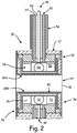
- stinger assembly 30 includes first stinger cup 52 which carries magnetic field generator 54.
- First stinger cup 52 can be removably secured to contactor shaft 56 and is selectively actuated to be in contact with first end surface 38A of cathode 24.
- First stinger cup 52 and contactor shaft 56 of stinger assembly 30 can be fabricated from an electrically conductive material such as a copper alloy.
- a first magnetic field generator 54 which may be enclosed by cover 57, can include, for example, a plurality of magnets 58.
- Magnets 58 are disposed in first stinger cup 52, and can be cooled by water or an aqueous solution via cooling tube 60. Cooling tube 60 can be coaxially positioned with contactor shaft 56 having coaxial ports 62 and 64. This arrangement allows coolant to efficiently enter and exit first magnetic field generator 54 via cooling tube 60.
- magnets 58 can be manipulated so as to create a rotating or otherwise traveling magnetic field adapted to steer the electric arc about cathode 24, ensuring even displacement of coating material from evaporative surface(s) 36.
- Magnets 58 can be permanent magnets, electromagnets, or the like, and thus operated (e.g., via rotation, switching, etc.) to steer the electric arc in any desired manner.
- First stinger cup 52 can have a multi-part configuration so as to provide increased thermal separation between magnetic field generator 54 and cathode 24.
- Large thermal gradients can be present in the stinger cup as a result of cooling requirements for the magnetic field generator.
- a large thermal gradient through the cup, between the magnets and the cathode results in thermal stress cracking of the cathode.
- Reducing the cooling rate to manage the thermal gradient can increase the risk of coolant boiling, creating damaging steam in systems designed for liquid coolant.
- a higher temperature coolant can be used (e.g., by substituting glycol for some or all of the water), this can only partially alleviate thermal stress issues.
- the temperature of the stinger and the coolant can increase above the Curie temperature of the magnets, which in turn can cause loss of arc steering control due to a weakened or lost magnetic field.
- multi-piece first stinger cup 52 thermally separates liquid-cooled magnetic field generator 54 from cathode(s) 24.
- An insulating layer between adjacent spaced pieces of first stinger cup 52 allows for a larger thermal gradient between stinger assembly 30 and cathode(s) 24 without reducing effectiveness of first magnetic field generator 54.
- apparatus 20 includes a second magnetic field generator 70.
- Second magnetic field generator 70 can be, for example, a second plurality of magnets 72 disposed within cathode support base 74.
- Cathode support base 74 electrically insulated from vessel 22, can include second stinger cup 78.
- second stinger cup 78 is inverted relative to first stinger cup 52 such that second end surface 38B of cathode 24 can rest upon a substantially flat cup surface 80.
- cathode support base 74 can operate (in conjunction with second magnetic field generator 70) as an optional second stinger assembly with a construction similar to that of stinger assembly 30.
- Second cooling mechanism 82 (similar to first cooling tube 60) can also be provided for second magnetic field generator 70.
- second stinger cup 78 can also be a multi-part stinger cup also having at least first and second electrically conductive cup portions spaced apart by a thermally insulating layer.
- FIG. 3 shows an example two-part stinger cup 88 suitable for use as first stinger cup 52 and/or second stinger cup 72.
- Example stinger cup 88 includes first electrically conductive inner cup portion 90A with first radial flange 92A.
- Second electrically conductive outer cup portion 90B (with second radial flange 92B) is disposed about first inner cup portion 90A such that outer surface 94 of first inner cup portion 90A is spaced from a corresponding inner surface 96 of second outer cup portion 90B by thermally insulating layer 98.
- At least one of first and second cup portions 90A, 90B can be formed of a similar material as other parts of the stinger, such as copper or a copper alloy.
- first and second cup portions 90A, 90B can be joined around respective radial flanges 92A, 92B to leave non-metallic thermally insulating layer 98.
- thermally insulating layer 98 can include small amounts of residual air though it is generally maintained under vacuum. This can be done for example by sealing first and second cup portions 90A, 90B around respective radial flanges 92A, 92B in a reduced-pressure atmosphere. While stinger cup 88 is shown as a two-part cup with a single thermally insulating layer, it will be appreciated that three or more cup portions can be used with additional thermally insulating layer(s) therebetween.
- inventions of apparatus 20 as shown in FIGS. 1-3 can include various modes of operation including the following.
- One or more workpieces which may include at least one turbine or compressor airfoil, can be positioned in a cathodic arc deposition vessel such that a surface of the workpiece to be coated faces an evaporative surface of the cathode.
- a portion of a cathode's evaporative surface can be vaporized by generating an electrical arc between the cathode and an anode disposed in the vessel.
- the anode can be an inner surface of the vessel.
- the vaporized portion of the cathode is directed toward the workpiece(s) by biasing the surface to be coated with a negative potential equal to or less than a potential of the anode.
- the workpiece(s) can be negatively biased, for example, by one or more power supplies in electrical communication therewith.
- the electrical arc is steered about the cathode by operating a first magnetic field generator, which can be disposed in a first multi-part stinger cup in selective contact with the cathode.
- the first stinger cup can have at least a first electrically conductive cup portion spaced from a second electrically conductive cup portion by a thermally insulating layer therebetween. At least one of the first cup portion and the second cup portion can include copper or an alloy thereof.
- the thermally insulating layer can be a non-metallic composition such as air. The thermally insulating layer can be maintained under partial vacuum.
- the electrical arc can be further steered by operating a second magnetic field generator disposed within a second stinger cup, which forms at least a portion of a cathode support base.
- the second stinger cup can also include a multi-part cup with at least one electrically conductive cup portion spaced from other electrically conductive cup portion(s) by a thermal insulating layer.
- a cathodic arc coating apparatus includes a vessel, a cathode disposed in the vessel, and a stinger assembly.
- the stinger assembly includes a first magnetic field generator disposed in a first stinger cup in selective contact with the cathode.
- the first stinger cup has at least a first electrically conductive cup portion spaced from a second electrically conductive cup portion by a thermally insulating layer therebetween.
- a cathodic arc coating apparatus can optionally include, additionally and/or alternatively, any one or more of the following features, configurations and/or additional components:
- a cathodic arc coating apparatus includes a vessel; a cathode disposed in the vessel, the cathode having at least one evaporative surface; and a stinger assembly including at least a first magnetic field generator disposed in a first stinger cup in selective contact with the cathode; the first stinger cup having at least a first electrically conductive cup portion spaced from a second electrically conductive cup portion by a thermally insulating layer therebetween.
- a further example of the foregoing cathodic arc coating apparatus wherein at least one of the first electrically conductive cup portion and second electrically conductive cup portion is in selective contact with a first end surface of the cathode.
- cathodic arc coating apparatus wherein the cathode includes a puck comprising a metallic coating material.
- the metallic coating material comprises nickel, cobalt, chromium, aluminum, titanium, yttrium, zirconium, and alloys thereof.
- a further example of any of the foregoing cathodic arc coating apparatus wherein the vessel contains a gas under partial pressure, the gas selected from the group consisting of: oxygen, nitrogen, carbon dioxide, and combinations thereof.
- a further example of any of the foregoing cathodic arc coating apparatus wherein the apparatus further comprises a platter including a plurality of workpiece holders disposed about an axis of the cathode.
- a further example of any of the foregoing cathodic arc coating apparatus wherein at least one of the first cup portion and the second cup portion comprises copper.
- thermoly insulating layer is non-metallic.
- thermoly insulating layer comprises air
- a further example of any of the foregoing cathodic arc coating apparatus wherein the apparatus further comprises a cathode support base secured to, and electrically insulated from the vessel.
- a further example of any of the foregoing cathodic arc coating apparatus wherein the apparatus further comprises a second magnetic field generator disposed within the cathode support base.
- cathode support base comprises a second multi-part stinger cup
- the second multi-part stinger cup has at least a first electrically conductive cup portion spaced from a second electrically conductive cup portion by a thermally insulating layer.
- a method for coating a workpiece includes positioning the workpiece in a cathodic arc deposition vessel such that a surface of the workpiece to be coated faces an evaporative surface of the cathode.
- a portion of the cathode evaporative surface is vaporized by generating an electrical arc between the cathode and an anode disposed in the vessel, the vaporized portion of the cathode forming a metallic plasma.
- the metallic plasma is directed toward the workpiece by biasing the surface to be coated with a negative potential equal to or less than a potential of the anode.
- the electrical arc is steered about the cathode by operating a first magnetic field generator disposed in a first multi-part stinger cup in selective contact with the cathode.
- the first stinger cup has at least a first electrically conductive cup portion spaced from a second electrically conductive cup portion by a thermally insulating layer therebetween.
- a method according to an example of this disclosure includes positioning the workpiece in a cathodic arc deposition vessel such that a surface of the workpiece to be coated faces an evaporative surface of the cathode; vaporizing a portion of the cathode evaporative surface by generating an electrical arc between the cathode and an anode disposed in the vessel, the vaporized portion of the cathode forming a metallic plasma; directing the metallic plasma toward the workpiece by biasing the surface to be coated with a negative potential equal to or less than a potential of the anode; and steering the electrical arc about the cathode by operating a first magnetic field generator; the magnetic field generator disposed in a first multi-part stinger cup in selective contact with the cathode, and the first stinger cup having at least a first electrically conductive cup portion
- the method further comprises positioning a plurality of workpieces in the vessel such that a surface of each workpiece to be coated faces the evaporative surface of the cathode.
- thermally insulating layer is non-metallic.
- thermally insulating layer comprises air
- the method further comprises maintaining the thermally insulating layer under partial vacuum.
- the steering step further comprises operating a second magnetic field generator disposed within a second stinger cup.
- the second stinger cup comprises a multi-part cup with a first electrically conductive cup portion spaced from a second electrically conductive cup portion by a thermally insulating layer.
- the cathode comprises a puck including the evaporative surface formed from a first metallic material.
- the first metallic material is selected from the group consisting of: nickel, cobalt, chromium, aluminum, titanium, yttrium, zirconium, and alloys thereof.
- the method further comprises maintaining an inert atmosphere in the vessel; and solidifying the metallic plasma to form a metallic coating on the workpiece.
- the method further comprises introducing at least one gas into the vessel such that the electrical arc vaporizes a portion of the at least one gas to form a nonmetallic plasma; directing the nonmetallic plasma to the biased surface of the workpiece; and solidifying the nonmetallic plasma along with the metallic plasma to form a ceramic coating on the workpiece.
- the at least one gas is selected from the group consisting of: oxygen, nitrogen, carbon dioxide, and combinations thereof.
- a class of the ceramic coating material is selected from the group consisting of: oxides, nitrides, carbides, carbo-nitrides, oxycarbo-nitrides, and combinations thereof.
- the ceramic coating material is selected from the group consisting of: aluminum oxide, yttrium oxide, zirconium oxide, titanium nitride, and combinations thereof.
Landscapes
- Chemical & Material Sciences (AREA)
- Engineering & Computer Science (AREA)
- Physics & Mathematics (AREA)
- Plasma & Fusion (AREA)
- Analytical Chemistry (AREA)
- Chemical Kinetics & Catalysis (AREA)
- Materials Engineering (AREA)
- Mechanical Engineering (AREA)
- Metallurgy (AREA)
- Organic Chemistry (AREA)
- Physical Vapour Deposition (AREA)
- Plasma Technology (AREA)
Claims (15)
- Vorrichtung zur Beschichtung mittels eines kathodischen Lichtbogens, umfassend:ein Gefäß;eine Anode, die von einer Kathode (24) beabstandet ist, die in dem Gefäß angeordnet ist, wobei die Kathode mindestens eines Verdampfungsfläche aufweist;eine erste Stromversorgung (42A), die konfiguriert ist, um in der Kathode (24) ein elektrisches Potenzial zu erzeugen;Mittel zum Zurückhalten mindestens eines Werkstücks in dem Gefäß, sodass das mindestens eine Werkstück gegenüber der mindestens einen Verdampfungsfläche freiliegt;einen Auslöser (28) zum Auslösen eines Lichtbogens zwischen der Anode und der Kathode zum Verdampfen eines Teils der Verdampfungsfläche, um ein Metallplasma zu bilden;eine zweite Stromversorgung (42B), die konfiguriert ist, um das mindestens eine Werkstück mit einem negativen Potenzial vorzuspannen, das kleiner gleich ein Potenzial der Anode ist, wodurch das Metallplasma zu dem mindestens einen Werkstück geleitet wird; undeine Vorschubstangenanordnung (30), wobei die Vorschubstangenanordnung (30) mindestens einen ersten Magnetfeldgenerator (54) zum Lenken des Lichtbogens über die Verdampfungsfläche der Kathode (24) einschließt, dadurch gekennzeichnet, dass der mindestens eine erste Magnetfeldgenerator (54) in einem ersten elektrisch leitenden inneren Schalenteil (90A) angeordnet ist, der mit einem zweiten elektrisch leitenden äußeren Schalenteil (90B) in selektivem Kontakt mit der Kathode (24) verbunden ist, wobei eine erste Vorschubstangenschale (52) definiert wird, die eine wärmeisolierende Schicht (98) zwischen dem ersten elektrisch leitenden inneren Schalenteil und dem zweiten elektrisch leitenden äußeren Schalenteil aufweist, sodass die wärmeisolierende Schicht zwischen dem ersten Magnetfeldgenerator und der Kathode angeordnet ist, wenn die erste Vorschubstangenschale mit der Kathode in Kontakt steht.
- Vorrichtung nach Anspruch 1, wobei die Kathode (24) einen Puck einschließt, der eine Verdampfungsfläche (36) umfasst, die aus einem Metallmaterial gebildet wird, und wobei das Metallmaterial ein Metall umfasst, das aus der Gruppe ausgewählt ist, bestehend aus: Nickel, Cobalt, Chrom, Aluminium, Titan, Yttrium, Zirconium und Legierungen davon.
- Vorrichtung nach Anspruch 1, wobei das Gefäß eine inerte Atmosphäre enthält, oder wobei das Gefäß' (22) ein Gas unter Partialdruck enthält, wobei das Gas aus der Gruppe ausgewählt ist, bestehend aus: Sauerstoff, Stickstoff, Kohlenstoffdioxid und Kombinationen davon.
- Vorrichtung nach Anspruch 1, ferner umfassend:
eine Platte (48), einschließend eine Vielzahl von Werkstückhaltern, die um eine Achse der Kathode angeordnet sind, und wobei die Vielzahl von Werkstückhaltern angepasst ist, um mindestens ein Profil zurückzuhalten. - Vorrichtung nach Anspruch 1, wobei mindestens einer des ersten elektrisch leitenden inneren Schalenteils und des zweiten elektrisch leitenden äußeren Schalenteils Kupfer umfasst.
- Vorrichtung nach Anspruch 1, wobei die wärmeisolierende Schicht nicht metallisch ist, undwobei die wärmeisolierende Schicht Luft umfasst, oderwobei die wärmeisolierende Schicht unter Unterdruck gehalten wird.
- Vorrichtung nach Anspruch 1, ferner umfassend eine Kathodenträgerbasis (74), die an dem Gefäß (22) gesichert und davon elektrisch isoliert ist.
- Vorrichtung nach Anspruch 7, ferner umfassend: einen zweiten Magnetfeldgenerator (70), der innerhalb der Kathodenträgerbasis angeordnet ist, und wobei die Kathodenträgerbasis eine zweite mehrteilige Vorschubstangenschale umfasst, wobei die zweite mehrteilige Vorschubstangenschale mindestens einen ersten elektrisch leitenden Schalenteil aufweist, der von einem zweiten elektrisch leitenden Schalenteil durch eine wärmeisolierende Schicht dazwischen beabstandet ist.
- Verfahren zur Beschichtung eines Werkstücks, wobei das Verfahren Folgendes umfasst:Positionieren des Werkstücks in einem Gefäß für die kathodische Lichtbogenverdampfung, sodass eine Fläche des zu beschichtenden Werkstücks einer Verdampfungsfläche der Kathode zugewandt ist;Anlegen eines elektrischen Potenzials in der Kathode durch eine erste Stromversorgung;Verdampfen eines Teils der Kathodenverdampfungsfläche durch das Auslösen eines Lichtbogens zwischen der Kathode und einer Anode, die in dem Gefäß angeordnet sind, wobei der verdampfte Teil der Kathode ein Metallplasma bildet;Leiten des Metallplasmas zu dem Werkstück durch das Betreiben einer zweiten Stromversorgung, wobei die zu beschichtende Fläche mit einem negativen Potenzial vorgespannt wird, das kleiner gleich ein Potenzial der Anode ist; undLenken des Lichtbogens um die Kathodenverdampfungsfläche durch das Betreiben eines ersten Magnetfeldgenerators, wobei der Magnetfeldgenerator in einem ersten elektrisch leitenden inneren Schalenteil einer ersten mehrteiligen Vorschubstangenschale angeordnet ist, wobei der erste elektrisch leitende innere Schalenteil mit einem zweiten elektrisch leitenden äußeren Schalenteil in selektivem Kontakt mit der Kathode verbunden ist, wobei eine wärmeisolierende Schicht zwischen dem ersten elektrisch leitenden inneren Schalenteil und dem zweiten elektrisch leitenden äußeren Schalenteil definiert wird, sodass die wärmeisolierende Schicht zwischen dem ersten Magnetfeldgenerator und der Kathode angeordnet ist, wenn die erste mehrteilige Vorschubstangenschale mit der Kathode in Kontakt steht.
- Verfahren nach Anspruch 9, ferner umfassend:
Positionieren einer Vielzahl von Werkstücken in dem Gefäß (22), sodass eine Fläche jedes zu beschichtenden Werkstücks der Verdampfungsfläche der Kathode (24) zugewandt ist, und wobei die Vielzahl von Werkstücken mindestens ein Profil einschließt. - Verfahren nach Anspruch 9, wobei mindestens einer des ersten Schalenteils und des zweiten Schalenteils Kupfer umfasst.
- Verfahren nach Anspruch 9 oder 11, wobei die wärmeisolierende Schicht nicht metallisch ist, und wobei die wärmeisolierende Schicht vorzugsweise Luft umfasst, oder ferner umfassend:
Halten der wärmeisolierenden Schicht unter Unterdruck. - Verfahren nach Anspruch 9, wobei der Lenkschritt ferner Folgendes umfasst:
Betreiben eines zweiten Magnetfeldgenerators (70), der in einer zweiten Vorschubstangenschale angeordnet ist, und wobei die zweite Vorschubstangenschale vorzugsweise zumindest einen Teil einer Kathodenträgerbasis bildet, oder wobei die zweite Vorschubstangenschale eine mehrteilige Schale umfasst, wobei ein erster elektrisch leitender Schalenteil von einem zweiten elektrisch leitenden Schalenteil durch eine wärmeisolierende Schicht beabstandet ist. - Verfahren nach Anspruch 9, ferner umfassend:Aufrechterhalten einer inerten Atmosphäre in dem Gefäß (22); undVerfestigen des Metallplasmas, um eine Metallbeschichtung auf dem Werkstück zu bilden.
- Verfahren nach Anspruch 9, ferner umfassend:Einleiten von mindestens einem Gas in das Gefäß (22), sodass der Lichtbogen einen Teil des mindestens einen Gases verdampft, um ein nicht metallisches Plasma zu bilden;Leiten des nicht metallischen Plasmas zu der vorgespannten Fläche des Werkstücks; undVerfestigen des nicht metallischen Plasmas zusammen mit dem Metallplasma, um eine Keramikbeschichtung auf dem Werkstück zu bilden, und wobei das mindestens eine Gas aus der Gruppe ausgewählt ist, bestehend aus: Sauerstoff, Stickstoff, Kohlenstoffdioxid und Kombinationen davon, oder wobei die Keramikbeschichtung aus der Gruppe ausgewählt ist, bestehend aus: Oxiden, Nitriden, Carbiden, Carbonitriden, Oxycarbonitriden und Kombinationen davon, oder wobei die Keramikbeschichtung aus der Gruppe ausgewählt ist, bestehend aus: Aluminiumoxid, Yttriumoxid, Zirconiumoxid, Titannitrid und Kombinationen davon.
Applications Claiming Priority (2)
| Application Number | Priority Date | Filing Date | Title |
|---|---|---|---|
| US201361888182P | 2013-10-08 | 2013-10-08 | |
| PCT/US2014/057503 WO2015053956A1 (en) | 2013-10-08 | 2014-09-25 | Cathodic arc deposition apparatus and method |
Publications (3)
| Publication Number | Publication Date |
|---|---|
| EP3055441A1 EP3055441A1 (de) | 2016-08-17 |
| EP3055441A4 EP3055441A4 (de) | 2017-05-17 |
| EP3055441B1 true EP3055441B1 (de) | 2022-01-12 |
Family
ID=52813508
Family Applications (1)
| Application Number | Title | Priority Date | Filing Date |
|---|---|---|---|
| EP14852888.8A Active EP3055441B1 (de) | 2013-10-08 | 2014-09-25 | Vorrichtung und verfahren zur beschichtung eines werkstücks mittels kathodischer lichtbogenverdampfung |
Country Status (3)
| Country | Link |
|---|---|
| US (2) | US9786474B2 (de) |
| EP (1) | EP3055441B1 (de) |
| WO (1) | WO2015053956A1 (de) |
Families Citing this family (2)
| Publication number | Priority date | Publication date | Assignee | Title |
|---|---|---|---|---|
| JP5941016B2 (ja) * | 2013-05-27 | 2016-06-29 | 株式会社神戸製鋼所 | 成膜装置およびそれを用いた成膜方法 |
| US11270872B2 (en) | 2019-09-25 | 2022-03-08 | Western Digital Technologies, Inc. | Base conducting layer beneath graphite layer of ceramic cathode for use with cathodic arc deposition |
Family Cites Families (12)
| Publication number | Priority date | Publication date | Assignee | Title |
|---|---|---|---|---|
| US5518597A (en) * | 1995-03-28 | 1996-05-21 | Minnesota Mining And Manufacturing Company | Cathodic arc coating apparatus and method |
| DE69824356T2 (de) | 1997-08-30 | 2005-02-17 | United Technologies Corp. (N.D.Ges.D. Staates Delaware), Hartford | Kathodisches Bogen-Beschichtungsgerät mit einer Vorrichtung zur Bogenführung |
| US6036828A (en) * | 1997-08-30 | 2000-03-14 | United Technologies Corporation | Apparatus for steering the arc in a cathodic arc coater |
| US6009829A (en) | 1997-08-30 | 2000-01-04 | United Technologies Corporation | Apparatus for driving the arc in a cathodic arc coater |
| US5972185A (en) | 1997-08-30 | 1999-10-26 | United Technologies Corporation | Cathodic arc vapor deposition apparatus (annular cathode) |
| US5932078A (en) | 1997-08-30 | 1999-08-03 | United Technologies Corporation | Cathodic arc vapor deposition apparatus |
| SG118232A1 (en) | 2004-02-27 | 2006-06-27 | Superiorcoat Private Ltd | Cathodic arc coating apparatus |
| US8241468B2 (en) * | 2004-12-13 | 2012-08-14 | United Technologies Corporation | Method and apparatus for cathodic arc deposition of materials on a substrate |
| US7879203B2 (en) | 2006-12-11 | 2011-02-01 | General Electric Company | Method and apparatus for cathodic arc ion plasma deposition |
| US8088260B2 (en) | 2007-08-14 | 2012-01-03 | United Technologies Corporation | Puck for cathodic arc coating with continuous groove to control arc |
| US8968528B2 (en) * | 2008-04-14 | 2015-03-03 | United Technologies Corporation | Platinum-modified cathodic arc coating |
| EP2276053A1 (de) | 2009-07-13 | 2011-01-19 | Applied Materials, Inc. | Targetsicherungsrohr, zylinderförmige Targetanordnung und Sputtersystem |
-
2014
- 2014-09-25 EP EP14852888.8A patent/EP3055441B1/de active Active
- 2014-09-25 US US15/027,643 patent/US9786474B2/en active Active
- 2014-09-25 WO PCT/US2014/057503 patent/WO2015053956A1/en not_active Ceased
-
2017
- 2017-09-08 US US15/699,429 patent/US10515785B2/en active Active
Also Published As
| Publication number | Publication date |
|---|---|
| EP3055441A1 (de) | 2016-08-17 |
| US9786474B2 (en) | 2017-10-10 |
| US20160260583A1 (en) | 2016-09-08 |
| EP3055441A4 (de) | 2017-05-17 |
| US10515785B2 (en) | 2019-12-24 |
| WO2015053956A1 (en) | 2015-04-16 |
| US20170372871A1 (en) | 2017-12-28 |
Similar Documents
| Publication | Publication Date | Title |
|---|---|---|
| US7879203B2 (en) | Method and apparatus for cathodic arc ion plasma deposition | |
| EP0899772B1 (de) | Kathodenbogen-Beschichtungsgerät | |
| US6036828A (en) | Apparatus for steering the arc in a cathodic arc coater | |
| EP0905272B1 (de) | Dampfphasenabscheidungsgerät mit kathodischem Lichtbogen (Ringförmige Kathode) | |
| US20210069778A1 (en) | Surface treated additive manufacturing printhead nozzles and methods for the same | |
| EP1719147B1 (de) | Fluidgekühlte ionenquelle | |
| US10515785B2 (en) | Cathodic arc deposition apparatus and method | |
| JP4985490B2 (ja) | 成膜装置 | |
| JP2011518954A (ja) | 蒸着システム | |
| US6009829A (en) | Apparatus for driving the arc in a cathodic arc coater | |
| JP2001040467A (ja) | アーク蒸発源、真空蒸着装置及び真空蒸着方法 | |
| US8241468B2 (en) | Method and apparatus for cathodic arc deposition of materials on a substrate | |
| EP1347491B1 (de) | Vorrichtung zur Bogenführung in einem kathodischen Bogen-Beschichtungsgerät | |
| US20190368033A1 (en) | Selective vapor deposition process for additive manufacturing | |
| WO2015057875A1 (en) | Assembly and method of coating an interior surface of an object | |
| US10704136B2 (en) | Cathodic arc deposition stinger | |
| US20090242397A1 (en) | Systems for controlling cathodic arc discharge | |
| KR20250004231A (ko) | 반도체 장비 부품용 코팅 시스템 및 코팅 방법 | |
| JP2017174514A (ja) | アーク式蒸発源、成膜装置及び成膜体の製造方法 | |
| MXPA05013515A (en) | Method and apparatus for cathodic arc deposition of materials on a substrate | |
| JP2010229502A (ja) | 成膜装置および成膜装置用ハース | |
| JP2016130330A (ja) | アーク成膜装置およびアーク成膜方法、ならびに固体蒸発材 |
Legal Events
| Date | Code | Title | Description |
|---|---|---|---|
| PUAI | Public reference made under article 153(3) epc to a published international application that has entered the european phase |
Free format text: ORIGINAL CODE: 0009012 |
|
| 17P | Request for examination filed |
Effective date: 20160509 |
|
| AK | Designated contracting states |
Kind code of ref document: A1 Designated state(s): AL AT BE BG CH CY CZ DE DK EE ES FI FR GB GR HR HU IE IS IT LI LT LU LV MC MK MT NL NO PL PT RO RS SE SI SK SM TR |
|
| AX | Request for extension of the european patent |
Extension state: BA ME |
|
| RAP1 | Party data changed (applicant data changed or rights of an application transferred) |
Owner name: UNITED TECHNOLOGIES CORPORATION |
|
| RIN1 | Information on inventor provided before grant (corrected) |
Inventor name: BALZANO, THOMAS Inventor name: BEERS, RUSSELL A. |
|
| DAX | Request for extension of the european patent (deleted) | ||
| A4 | Supplementary search report drawn up and despatched |
Effective date: 20170419 |
|
| RIC1 | Information provided on ipc code assigned before grant |
Ipc: H01J 37/32 20060101ALI20170411BHEP Ipc: C23C 14/32 20060101AFI20170411BHEP |
|
| STAA | Information on the status of an ep patent application or granted ep patent |
Free format text: STATUS: EXAMINATION IS IN PROGRESS |
|
| 17Q | First examination report despatched |
Effective date: 20190606 |
|
| RAP1 | Party data changed (applicant data changed or rights of an application transferred) |
Owner name: RAYTHEON TECHNOLOGIES CORPORATION |
|
| GRAP | Despatch of communication of intention to grant a patent |
Free format text: ORIGINAL CODE: EPIDOSNIGR1 |
|
| RIC1 | Information provided on ipc code assigned before grant |
Ipc: C23C 14/32 20060101AFI20210702BHEP Ipc: H01J 37/32 20060101ALI20210702BHEP Ipc: H01J 37/34 20060101ALI20210702BHEP |
|
| STAA | Information on the status of an ep patent application or granted ep patent |
Free format text: STATUS: GRANT OF PATENT IS INTENDED |
|
| INTG | Intention to grant announced |
Effective date: 20210812 |
|
| GRAS | Grant fee paid |
Free format text: ORIGINAL CODE: EPIDOSNIGR3 |
|
| GRAA | (expected) grant |
Free format text: ORIGINAL CODE: 0009210 |
|
| STAA | Information on the status of an ep patent application or granted ep patent |
Free format text: STATUS: THE PATENT HAS BEEN GRANTED |
|
| AK | Designated contracting states |
Kind code of ref document: B1 Designated state(s): AL AT BE BG CH CY CZ DE DK EE ES FI FR GB GR HR HU IE IS IT LI LT LU LV MC MK MT NL NO PL PT RO RS SE SI SK SM TR |
|
| REG | Reference to a national code |
Ref country code: GB Ref legal event code: FG4D |
|
| REG | Reference to a national code |
Ref country code: CH Ref legal event code: EP |
|
| REG | Reference to a national code |
Ref country code: DE Ref legal event code: R096 Ref document number: 602014082180 Country of ref document: DE |
|
| REG | Reference to a national code |
Ref country code: IE Ref legal event code: FG4D |
|
| REG | Reference to a national code |
Ref country code: AT Ref legal event code: REF Ref document number: 1462436 Country of ref document: AT Kind code of ref document: T Effective date: 20220215 |
|
| REG | Reference to a national code |
Ref country code: LT Ref legal event code: MG9D |
|
| REG | Reference to a national code |
Ref country code: NL Ref legal event code: MP Effective date: 20220112 |
|
| REG | Reference to a national code |
Ref country code: AT Ref legal event code: MK05 Ref document number: 1462436 Country of ref document: AT Kind code of ref document: T Effective date: 20220112 |
|
| PG25 | Lapsed in a contracting state [announced via postgrant information from national office to epo] |
Ref country code: NL Free format text: LAPSE BECAUSE OF FAILURE TO SUBMIT A TRANSLATION OF THE DESCRIPTION OR TO PAY THE FEE WITHIN THE PRESCRIBED TIME-LIMIT Effective date: 20220112 |
|
| PG25 | Lapsed in a contracting state [announced via postgrant information from national office to epo] |
Ref country code: SE Free format text: LAPSE BECAUSE OF FAILURE TO SUBMIT A TRANSLATION OF THE DESCRIPTION OR TO PAY THE FEE WITHIN THE PRESCRIBED TIME-LIMIT Effective date: 20220112 Ref country code: RS Free format text: LAPSE BECAUSE OF FAILURE TO SUBMIT A TRANSLATION OF THE DESCRIPTION OR TO PAY THE FEE WITHIN THE PRESCRIBED TIME-LIMIT Effective date: 20220112 Ref country code: PT Free format text: LAPSE BECAUSE OF FAILURE TO SUBMIT A TRANSLATION OF THE DESCRIPTION OR TO PAY THE FEE WITHIN THE PRESCRIBED TIME-LIMIT Effective date: 20220512 Ref country code: NO Free format text: LAPSE BECAUSE OF FAILURE TO SUBMIT A TRANSLATION OF THE DESCRIPTION OR TO PAY THE FEE WITHIN THE PRESCRIBED TIME-LIMIT Effective date: 20220412 Ref country code: LT Free format text: LAPSE BECAUSE OF FAILURE TO SUBMIT A TRANSLATION OF THE DESCRIPTION OR TO PAY THE FEE WITHIN THE PRESCRIBED TIME-LIMIT Effective date: 20220112 Ref country code: HR Free format text: LAPSE BECAUSE OF FAILURE TO SUBMIT A TRANSLATION OF THE DESCRIPTION OR TO PAY THE FEE WITHIN THE PRESCRIBED TIME-LIMIT Effective date: 20220112 Ref country code: ES Free format text: LAPSE BECAUSE OF FAILURE TO SUBMIT A TRANSLATION OF THE DESCRIPTION OR TO PAY THE FEE WITHIN THE PRESCRIBED TIME-LIMIT Effective date: 20220112 Ref country code: BG Free format text: LAPSE BECAUSE OF FAILURE TO SUBMIT A TRANSLATION OF THE DESCRIPTION OR TO PAY THE FEE WITHIN THE PRESCRIBED TIME-LIMIT Effective date: 20220412 |
|
| PG25 | Lapsed in a contracting state [announced via postgrant information from national office to epo] |
Ref country code: PL Free format text: LAPSE BECAUSE OF FAILURE TO SUBMIT A TRANSLATION OF THE DESCRIPTION OR TO PAY THE FEE WITHIN THE PRESCRIBED TIME-LIMIT Effective date: 20220112 Ref country code: LV Free format text: LAPSE BECAUSE OF FAILURE TO SUBMIT A TRANSLATION OF THE DESCRIPTION OR TO PAY THE FEE WITHIN THE PRESCRIBED TIME-LIMIT Effective date: 20220112 Ref country code: GR Free format text: LAPSE BECAUSE OF FAILURE TO SUBMIT A TRANSLATION OF THE DESCRIPTION OR TO PAY THE FEE WITHIN THE PRESCRIBED TIME-LIMIT Effective date: 20220413 Ref country code: FI Free format text: LAPSE BECAUSE OF FAILURE TO SUBMIT A TRANSLATION OF THE DESCRIPTION OR TO PAY THE FEE WITHIN THE PRESCRIBED TIME-LIMIT Effective date: 20220112 Ref country code: AT Free format text: LAPSE BECAUSE OF FAILURE TO SUBMIT A TRANSLATION OF THE DESCRIPTION OR TO PAY THE FEE WITHIN THE PRESCRIBED TIME-LIMIT Effective date: 20220112 |
|
| PG25 | Lapsed in a contracting state [announced via postgrant information from national office to epo] |
Ref country code: IS Free format text: LAPSE BECAUSE OF FAILURE TO SUBMIT A TRANSLATION OF THE DESCRIPTION OR TO PAY THE FEE WITHIN THE PRESCRIBED TIME-LIMIT Effective date: 20220512 |
|
| REG | Reference to a national code |
Ref country code: DE Ref legal event code: R097 Ref document number: 602014082180 Country of ref document: DE |
|
| PG25 | Lapsed in a contracting state [announced via postgrant information from national office to epo] |
Ref country code: SM Free format text: LAPSE BECAUSE OF FAILURE TO SUBMIT A TRANSLATION OF THE DESCRIPTION OR TO PAY THE FEE WITHIN THE PRESCRIBED TIME-LIMIT Effective date: 20220112 Ref country code: SK Free format text: LAPSE BECAUSE OF FAILURE TO SUBMIT A TRANSLATION OF THE DESCRIPTION OR TO PAY THE FEE WITHIN THE PRESCRIBED TIME-LIMIT Effective date: 20220112 Ref country code: RO Free format text: LAPSE BECAUSE OF FAILURE TO SUBMIT A TRANSLATION OF THE DESCRIPTION OR TO PAY THE FEE WITHIN THE PRESCRIBED TIME-LIMIT Effective date: 20220112 Ref country code: EE Free format text: LAPSE BECAUSE OF FAILURE TO SUBMIT A TRANSLATION OF THE DESCRIPTION OR TO PAY THE FEE WITHIN THE PRESCRIBED TIME-LIMIT Effective date: 20220112 Ref country code: DK Free format text: LAPSE BECAUSE OF FAILURE TO SUBMIT A TRANSLATION OF THE DESCRIPTION OR TO PAY THE FEE WITHIN THE PRESCRIBED TIME-LIMIT Effective date: 20220112 Ref country code: CZ Free format text: LAPSE BECAUSE OF FAILURE TO SUBMIT A TRANSLATION OF THE DESCRIPTION OR TO PAY THE FEE WITHIN THE PRESCRIBED TIME-LIMIT Effective date: 20220112 |
|
| PLBE | No opposition filed within time limit |
Free format text: ORIGINAL CODE: 0009261 |
|
| STAA | Information on the status of an ep patent application or granted ep patent |
Free format text: STATUS: NO OPPOSITION FILED WITHIN TIME LIMIT |
|
| PG25 | Lapsed in a contracting state [announced via postgrant information from national office to epo] |
Ref country code: AL Free format text: LAPSE BECAUSE OF FAILURE TO SUBMIT A TRANSLATION OF THE DESCRIPTION OR TO PAY THE FEE WITHIN THE PRESCRIBED TIME-LIMIT Effective date: 20220112 |
|
| 26N | No opposition filed |
Effective date: 20221013 |
|
| PG25 | Lapsed in a contracting state [announced via postgrant information from national office to epo] |
Ref country code: SI Free format text: LAPSE BECAUSE OF FAILURE TO SUBMIT A TRANSLATION OF THE DESCRIPTION OR TO PAY THE FEE WITHIN THE PRESCRIBED TIME-LIMIT Effective date: 20220112 |
|
| PG25 | Lapsed in a contracting state [announced via postgrant information from national office to epo] |
Ref country code: MC Free format text: LAPSE BECAUSE OF FAILURE TO SUBMIT A TRANSLATION OF THE DESCRIPTION OR TO PAY THE FEE WITHIN THE PRESCRIBED TIME-LIMIT Effective date: 20220112 |
|
| REG | Reference to a national code |
Ref country code: CH Ref legal event code: PL |
|
| REG | Reference to a national code |
Ref country code: BE Ref legal event code: MM Effective date: 20220930 |
|
| P01 | Opt-out of the competence of the unified patent court (upc) registered |
Effective date: 20230520 |
|
| PG25 | Lapsed in a contracting state [announced via postgrant information from national office to epo] |
Ref country code: LU Free format text: LAPSE BECAUSE OF NON-PAYMENT OF DUE FEES Effective date: 20220925 |
|
| PG25 | Lapsed in a contracting state [announced via postgrant information from national office to epo] |
Ref country code: LI Free format text: LAPSE BECAUSE OF NON-PAYMENT OF DUE FEES Effective date: 20220930 Ref country code: IT Free format text: LAPSE BECAUSE OF FAILURE TO SUBMIT A TRANSLATION OF THE DESCRIPTION OR TO PAY THE FEE WITHIN THE PRESCRIBED TIME-LIMIT Effective date: 20220112 Ref country code: IE Free format text: LAPSE BECAUSE OF NON-PAYMENT OF DUE FEES Effective date: 20220925 Ref country code: CH Free format text: LAPSE BECAUSE OF NON-PAYMENT OF DUE FEES Effective date: 20220930 |
|
| PG25 | Lapsed in a contracting state [announced via postgrant information from national office to epo] |
Ref country code: BE Free format text: LAPSE BECAUSE OF NON-PAYMENT OF DUE FEES Effective date: 20220930 |
|
| PG25 | Lapsed in a contracting state [announced via postgrant information from national office to epo] |
Ref country code: HU Free format text: LAPSE BECAUSE OF FAILURE TO SUBMIT A TRANSLATION OF THE DESCRIPTION OR TO PAY THE FEE WITHIN THE PRESCRIBED TIME-LIMIT; INVALID AB INITIO Effective date: 20140925 |
|
| PG25 | Lapsed in a contracting state [announced via postgrant information from national office to epo] |
Ref country code: CY Free format text: LAPSE BECAUSE OF FAILURE TO SUBMIT A TRANSLATION OF THE DESCRIPTION OR TO PAY THE FEE WITHIN THE PRESCRIBED TIME-LIMIT Effective date: 20220112 |
|
| PG25 | Lapsed in a contracting state [announced via postgrant information from national office to epo] |
Ref country code: MK Free format text: LAPSE BECAUSE OF FAILURE TO SUBMIT A TRANSLATION OF THE DESCRIPTION OR TO PAY THE FEE WITHIN THE PRESCRIBED TIME-LIMIT Effective date: 20220112 |
|
| PG25 | Lapsed in a contracting state [announced via postgrant information from national office to epo] |
Ref country code: MT Free format text: LAPSE BECAUSE OF FAILURE TO SUBMIT A TRANSLATION OF THE DESCRIPTION OR TO PAY THE FEE WITHIN THE PRESCRIBED TIME-LIMIT Effective date: 20220112 |
|
| REG | Reference to a national code |
Ref country code: DE Ref legal event code: R081 Ref document number: 602014082180 Country of ref document: DE Owner name: RTX CORPORATION (N.D.GES.D. STAATES DELAWARE),, US Free format text: FORMER OWNER: RAYTHEON TECHNOLOGIES CORPORATION, FARMINGTON, CT, US |
|
| PGFP | Annual fee paid to national office [announced via postgrant information from national office to epo] |
Ref country code: DE Payment date: 20250820 Year of fee payment: 12 |
|
| PGFP | Annual fee paid to national office [announced via postgrant information from national office to epo] |
Ref country code: GB Payment date: 20250822 Year of fee payment: 12 |
|
| PGFP | Annual fee paid to national office [announced via postgrant information from national office to epo] |
Ref country code: FR Payment date: 20250820 Year of fee payment: 12 |
|
| PG25 | Lapsed in a contracting state [announced via postgrant information from national office to epo] |
Ref country code: TR Free format text: LAPSE BECAUSE OF FAILURE TO SUBMIT A TRANSLATION OF THE DESCRIPTION OR TO PAY THE FEE WITHIN THE PRESCRIBED TIME-LIMIT Effective date: 20220112 |