EP3055145B1 - System zur indirekten überwachung des reifendrucks von pneumatischen fahrzeugrädern und fahrzeugrad dafür - Google Patents
System zur indirekten überwachung des reifendrucks von pneumatischen fahrzeugrädern und fahrzeugrad dafür Download PDFInfo
- Publication number
- EP3055145B1 EP3055145B1 EP14787291.5A EP14787291A EP3055145B1 EP 3055145 B1 EP3055145 B1 EP 3055145B1 EP 14787291 A EP14787291 A EP 14787291A EP 3055145 B1 EP3055145 B1 EP 3055145B1
- Authority
- EP
- European Patent Office
- Prior art keywords
- sensor
- deformation sensor
- wheel
- vehicle
- deformation
- Prior art date
- Legal status (The legal status is an assumption and is not a legal conclusion. Google has not performed a legal analysis and makes no representation as to the accuracy of the status listed.)
- Active
Links
Images

Classifications
-
- B—PERFORMING OPERATIONS; TRANSPORTING
- B60—VEHICLES IN GENERAL
- B60C—VEHICLE TYRES; TYRE INFLATION; TYRE CHANGING; CONNECTING VALVES TO INFLATABLE ELASTIC BODIES IN GENERAL; DEVICES OR ARRANGEMENTS RELATED TO TYRES
- B60C23/00—Devices for measuring, signalling, controlling, or distributing tyre pressure or temperature, specially adapted for mounting on vehicles; Arrangement of tyre inflating devices on vehicles, e.g. of pumps or of tanks; Tyre cooling arrangements
- B60C23/06—Signalling devices actuated by deformation of the tyre, e.g. tyre mounted deformation sensors or indirect determination of tyre deformation based on wheel speed, wheel-centre to ground distance or inclination of wheel axle
-
- B—PERFORMING OPERATIONS; TRANSPORTING
- B60—VEHICLES IN GENERAL
- B60C—VEHICLE TYRES; TYRE INFLATION; TYRE CHANGING; CONNECTING VALVES TO INFLATABLE ELASTIC BODIES IN GENERAL; DEVICES OR ARRANGEMENTS RELATED TO TYRES
- B60C23/00—Devices for measuring, signalling, controlling, or distributing tyre pressure or temperature, specially adapted for mounting on vehicles; Arrangement of tyre inflating devices on vehicles, e.g. of pumps or of tanks; Tyre cooling arrangements
- B60C23/001—Devices for manually or automatically controlling or distributing tyre pressure whilst the vehicle is moving
- B60C23/004—Devices for manually or automatically controlling or distributing tyre pressure whilst the vehicle is moving the control being done on the wheel, e.g. using a wheel-mounted reservoir
-
- B—PERFORMING OPERATIONS; TRANSPORTING
- B60—VEHICLES IN GENERAL
- B60C—VEHICLE TYRES; TYRE INFLATION; TYRE CHANGING; CONNECTING VALVES TO INFLATABLE ELASTIC BODIES IN GENERAL; DEVICES OR ARRANGEMENTS RELATED TO TYRES
- B60C23/00—Devices for measuring, signalling, controlling, or distributing tyre pressure or temperature, specially adapted for mounting on vehicles; Arrangement of tyre inflating devices on vehicles, e.g. of pumps or of tanks; Tyre cooling arrangements
- B60C23/06—Signalling devices actuated by deformation of the tyre, e.g. tyre mounted deformation sensors or indirect determination of tyre deformation based on wheel speed, wheel-centre to ground distance or inclination of wheel axle
- B60C23/064—Signalling devices actuated by deformation of the tyre, e.g. tyre mounted deformation sensors or indirect determination of tyre deformation based on wheel speed, wheel-centre to ground distance or inclination of wheel axle comprising tyre mounted deformation sensors, e.g. to determine road contact area
Definitions
- the invention relates to a system for indirectly monitoring the inflation pressure of a pneumatic-tyred vehicle wheel on vehicles, comprising at least one wheel body with a rim part and a disc part, comprising a tyre detachably fitted on the rim part of the wheel body, comprising a valve fitted in the wheel body and intended for changing the inflation pressure in the tyre, comprising at least one sensor for sensing the tyre inflation pressure at the time, comprising a data transmission device for transmitting sensor signals of the at least one sensor to an evaluation device, and comprising an evaluation device for evaluating the sensor signals, the at least one sensor being a deformation sensor.
- the invention also relates to a vehicle wheel for such a system comprising a wheel body, which has a disc part that can be fastened to a vehicle axle of a vehicle and a rim part for receiving a tyre, the wheel body being provided with a valve hole for fitting a valve for optionally changing an inflation pressure in the fitted tyre.
- TPMS tyre pressure monitoring systems
- TPMS tyre pressure monitoring systems
- the directly measuring tyre pressure monitoring systems use relatively expensive and heavy sensors along with wheel electronics, which in each case leads to an imbalance in the vehicle wheel, which in turn has to be compensated by way of balancing weights.
- balancing weights When a vehicle wheel is changed, there is an increased risk of damage to the inflation pressure sensor and/or the wheel electronics.
- leakage problems can occur, in particular in the case of high-speed vehicle wheels, for example on account of the centrifugal forces.
- Changed wheel geometries with minimal well depths or narrow well widths may also lead to problems in the fitting of valves equipped with directly measuring sensors.
- the mounting and/or further processing of the vehicle wheels may lead to damage to the valves unless corresponding measures are taken to protect these valves, thereby increasing the handling effort involved.
- DE 100 01 272 A1 discloses a system and method for determining loads acting on tyres of vehicle wheels .
- the rim of the vehicle wheel is equipped with a surface acoustic wave sensor, taking advantage of the piezoelectric effect and operating to sense rim strains both in circumferential direction and transverse direction of the rim.
- the sensor signal transferred to an onboard computer to control and manipulate the anti-lock braking system (ABS),acceleration slip regulation (ASR) or the electronic stability program (ESP).
- ABS anti-lock braking system
- ASR acceleration slip regulation
- ESP electronic stability program
- US 5 163 320 discloses a tyre inspection device for tyre wheels made from nonmctallic materials.
- the detecting part is equipped with a sensor and an electric circuit for conveying out of the wheel and electric sign corresponding to the sensor signal sensed by the sender.
- the said sensor could be a strain sensor for measuring strains, a temperature sensor for measuring temperature or the pressure sensor for direct measuring of the internal pressure within the wheel.
- DE 101 46 031 A1 It is also known for example from DE 101 46 031 A1 to monitor the inflation pressure of a vehicle wheel by way of an indirect inflation pressure monitoring system.
- the previously known indirect inflation pressure monitoring systems rely on embedding a deformation sensor in the vehicle tyre and then using the measuring signals from the sensor for sensing and determining the tyre inflation pressure at the time.
- a deformation sensor of the surface wave type is used, designed as a radio sensor and generating a signal corresponding to the respective deformation of the running surface, in particular in the circumferential direction, which is transmitted wirelessly to a signal receiver, which passes it on to an evaluation computer.
- the evaluation computer uses characteristic maps previously recorded for a prescribed type of tyre, and stored in a map memory, for determining the inflation pressure of a tyre.
- the object of the invention is to provide a system and vehicle wheels that are simplified in comparison with the tyre pressure monitoring system previously used and minimize or avoid the aforementioned disadvantages of the known solutions.
- This correlation between the inflation pressure in a pneumatic-tyred vehicle wheel on the one hand and the deformations of the wheel body caused by the tyre pressure prevailing on the other hand can therefore be used for the indirect measurement or determination of the inflation pressure, the characteristics of the correlation allowing the measured deformation to be evaluated as a qualitative measure and also as a quantitative measure of the tyre pressure.
- the evaluation device for determining the inflation pressure may in particular be a component part of the electronic system of the vehicle. It is also advantageous if the tyre pressure monitoring system uses an inductive energy supply of the deformation sensor and/or of the transmission device for the measuring signals of the deformation sensor assigned to the wheel body.
- a deformation sensor for sensing inflation-pressure-dependent deformations of the wheel body of a pneumatic-tyred vehicle wheel is fitted on the wheel body.
- the deformation sensor is evaluated in the fitted state of the tyred vehicle wheel on the axle of a vehicle.
- the inflation pressure of an emergency or spare wheel that is possibly not fitted but only taken along with the vehicle could also be monitored. It is particularly advantageous both for the tyre pressure monitoring system and for the vehicle wheel if the deformation sensor is fitted on the rim part of the wheel body, since the inflation-pressure-induced deformations in the wheel body occur primarily in the wheel rim.
- the deformation sensor is attached to the radial outer side of the rim part.
- a favourable position for attaching the deformation sensor is where the rim part has radii or radii transitions.
- the rim part of the wheel body is provided with a well and the deformation sensor is fitted on the rim part in the region of the well.
- the deformation sensor is arranged in a transition radius between a well base and a well flank.
- the deformation sensor or sensors is/are preferably attached to the wheel body parallel to the wheel axis of the vehicle wheel or transversely to the wheel axis at an angle of ⁇ 45°, so that they therefore sense the deformations transversely to the running direction of the vehicle wheel.
- the deformation sensor or sensors is/are preferably attached to the wheel body fixedly, in particular undetachably, preferably on or at the surface of the rim.
- This solution is advantageous in particular in the case of the preferred application area, that is light-alloy wheels and steel wheels or hybrid vehicle wheels comprising a steel rim and a light-alloy disc.
- the output signals of a single deformation sensor may be used for measuring the inflation pressure.
- the system or the vehicle wheel may, however, also comprise deformation sensors with multiple sensor cells or multiple deformation sensors, which are attached to the wheel body at a distance from one another. Irrespective of whether one deformation sensor or multiple deformation sensors or deformation sensors comprising multiple sensor cells are used, the corresponding deformation sensors may in particular consist of strain gauges (strain gauge sensors) or comprise strain gauges.
- strain gauge sensors strain gauge sensors
- Corresponding deformation sensors can be fitted without any problem, in particular to the radial outer side on the rim part of the vehicle wheel. By being arranged in the interior space of the tyre, they are then protected to the greatest extent from environmental influences during operational use on the vehicle.
- Deformation sensors such as for example strain gauge sensors have an extremely low weight, a small overall size, are flexible and can be attached to the wheel body securely and without the risk of becoming unintentionally detached. It is particularly advantageous if the deformation sensor is a component part of an (in particular passive) RFID transponder, in the case of which the sensor measuring cell and the transmission device are an integral component part and at the same time there is no dedicated energy source, but instead the energy required for reading out and transmitting the evaluation signals, preferably by way of an antenna device of the transponder, is generated from the received radio waves of a reading or receiving device connected to the evaluation device.
- active RFID transponders could also be used, correspondingly having a dedicated energy supply. Passive RFID transponders are preferred however.
- the system may also be used for monitoring loading, in that the measuring signals of the same deformation sensor, or the measuring signals of a further deformation sensor, are evaluated for monitoring the static wheel load.
- the invention also includes a method-related aspect, that is the detection and evaluation of the inflation-pressure-dependent deformation of the wheel body, in particular the wheel rim, in order to make quantitative and/or qualitative monitoring of the tyre pressure possible by way of an indirectly measuring system.
- a method-related aspect that is the detection and evaluation of the inflation-pressure-dependent deformation of the wheel body, in particular the wheel rim, in order to make quantitative and/or qualitative monitoring of the tyre pressure possible by way of an indirectly measuring system.
- the output signals of a deformation sensor fastened to the wheel body are transmitted to an evaluation device and compared with reference values that have previously been determined in a calibrating operation for the vehicle wheel being used. From the signals of the deformation sensor, in particular from the amplitude of the deformation with respect to an average deformation value corresponding to the tyre inflation pressure, the loading state of the vehicle could also be determined.
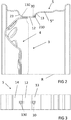
- a system for monitoring the tyre pressure that is denoted as a whole by reference numeral 10 is schematically represented in a greatly simplified form.
- the body of a vehicle 1 in the region of a wheelhouse on the vehicle is indicated by the dashed line.
- the vehicle wheel Fastened to the axle (not represented) of the vehicle 1 is the vehicle wheel, which is denoted as a whole by reference numeral 2 and is only half shown here.
- the vehicle wheel 2 has a two-part wheel body 3, which in a way known per se comprises a disc part 4 with a central hub connection surface and a rim part 5, which respectively consist of sheet metal, whereby they form a steel vehicle wheel 2.
- the vehicle wheel 2 could, however, also have a cast wheel body of aluminium, be configured as a hybrid wheel with a rim part of steel and a disc part of aluminium or have some other type of construction.
- a tyre 6 of any desired suitable type of construction is supported on the radial outer side 5' of the rim part 5, it being possible for the interior space 7 of the tyre to be filled with air by way of the valve 8, whereby the vehicle wheel 2 can be provided with the tyre internal pressure prescribed by the vehicle manufacturer for the respective vehicle load.
- the valve 8 is fastened to the outer-wheel well flank 9 of a well 11 in the rim part 5 that is denoted as a whole by reference numeral 11.
- the rim part 5 also has a well base 12, an inner-wheel well flank 13, two rim flanges 14, 15, two tapered bead seats 16, 17, against which the tyre 6 comes to lie respectively with a tyre bead 18, 19 in a sealing manner, a transitional flange 20, an outer safety bump 21 (or hump) between the outer well flank 9 and the outer tapered bead seat 16 and an inner safety bump 21A between the transitional flange 20 and the inner tapered bead seat 17.
- the disc part 4 is connected, in particular welded, to the radially inner underside of the well base 12 that lies facing the wheel axis R.
- a deformation sensor 30 that is schematically indicated in Figure 1 is attached to the wheel body 3 of the vehicle wheel 2 in order to detect those deformations that the rim part undergoes with the tyre 6 fitted, on account of the inflation pressure in the interior space 7 of the tyre 6.
- This deformation sensor 30 is for example a strain gauge, the deformation sensor 30 being positioned here in the transition radius 22 between the well base 12 and the inner well flank 13 and being attached directly to the rim part 5, to be specific on the radial outer side 5' of the rim part 5.
- the deformation sensor 30 therefore lies in the interior space 7 of the tyre.
- the system 10 has in the exemplary embodiment shown a reading or receiving device 40, which is fastened to the vehicle body 1, for example in the region of the wheel suspension or in the wheelhouse, and with which the signals of the deformation sensor 30 can be received.
- the reading device 40 may at the same time be provided for example with an antenna of a sufficient size in order to accomplish the energy supply for the deformation sensor 30 by inductive means.
- the deformation sensor 30 could then be configured for example as a passive RFID transponder, which transmits the deformation value at the respective time to the reading device 40.
- the reading device 40 in turn is coupled in signalling terms to an intelligent evaluation device 41, it being indicated in the exemplary embodiment shown that the evaluation device 41 could also form an integral component part of the vehicle's electronic system 42 that is provided in any case in modern vehicles.
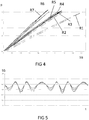
- FIG. 4 the correlation between the inflation pressure p (y axis) and the measured value determined with a strain gauge (SG) as a deformation sensor (x axis) is presented for a variously tyred vehicle wheel.
- the various tyred vehicle wheels are for example a steel vehicle wheel with tyres according to the following specifications [Table 1] R1 255/70 R16 R2 205/70 R16 R3 215/60 R16 R4 225/55 R16 DSST R5 225/55 R16 R6 195/55 R16 RFT R7 195/50 R16
- the measured value detected by the deformation sensors 38 also changes in dependence on for example the angle of the deformation sensor in relation to the centre of contact of the vehicle wheel, the properties of the carriageway and the travelling direction of the vehicle (straightahead, cornering, etc.).
- the inflation-pressure-dependently induced measuring signal of the deformation sensor is therefore superimposed by sinusoidal signals from driving operation, as represented by way of example for driving straightahead in the diagram that is shown in Figure 5 , the output signals delivered by the deformation sensors 38, here strain gauges, being plotted on the y axis and the time elapsed during a number of revolutions of the wheel being plotted on the x axis in Figure 5 .
- the three different curves correspond here to signal progressions with different vertical wheel loads. A virtually constant signal progression is obtained, it being evident that the degree of amplitude increases and correlates with an increase in the vertical wheel load. It is also found, however, that an inflation-pressure-dependent average deformation value can be determined from the values determined with a deformation sensor attached to the rim part of the wheel body and can be used to establish changes of the tyre pressure qualitatively and quantitatively with respect to reference values, and thereby used as a base signal for a system for monitoring the tyre pressure.
- the electronic system of the vehicle possibly requires suitable measurement and sensor dynamics for the sensors.
- a deviation of the existing tyre inflation pressure from the optimum or prescribed tyre pressure that allows safe driving and low tyre wear can be established and communicated to the vehicle driver by way of the vehicle's electronic system 42 and suitable indicating devices. It can be seen from Figure 5 that an average deformation value can be respectively determined loading-dependently, forming a quantitative measure of the tyre pressure existing in the pneumatic tyre fitted.
- a signal evaluation could be performed for example in such a way that a relatively great number of values sampled by the deformation sensors for the strain, for example 5000 to 10 000 sampled values, are electronically filtered in order to remove erroneous values on the basis of obvious outliers.
- the maximum strain and the minimum strain per cycle i.e. here preferably every 360° turn of the vehicle wheel, are determined.
- an average strain is determined from half the sum of the respectively measured maximum strain (Î max ) and minimum strain (Î min ), that is to say ((Î max - Î min )/2).
- an amplitude of the strain is also determined from half the difference between the measured maximum strain (Î max ) and minimum strain (Î min ), that is to say ((Î max - Î min )/2). These values are also preferably filtered again. If the average strain (corresponding to the assigned inflation pressure) and/or the amplitude of the strain (corresponding to the assigned inflation pressure) then deviate over a prescribed number of cycles, an alarm warning may be issued to the vehicle driver in any way desired.
- Strain-changing instances of cornering, driving over potholes, etc. are preferably thereby filtered out, the warnings preferably being indicated in the form of intelligent messages by way of the evaluation electronics.
- the error messages and indications to the vehicle driver are preferably based on the possible signal sequences and causes. For instance, when the average strain determined is below the prescribed average value by a tolerance value of for example 0.2 bar for the last x cycles, it could be indicated to the vehicle driver that this suggests a loss of inflation pressure, that the tyre pressure should be checked without delay and the system recalibrated.
- the average amplitude exceeds the tolerance value by a value z for the last x cycles, it could be indicated to the vehicle driver that the cause of this could be overloading, that the loading should be checked for correctness and the system recalibrated. If, on the other hand, the average amplitude is below the tolerance value by a value z for the last x cycles, the cause could be low loading, for which reason a recalibration of the system could be recommended. If, on the other hand, the average strain exceeds the tolerance value of 0.2 bar with respect to the prescribed average value for the last x cycles, the cause could be overloading or excessive inflation pressure, which could correspondingly be indicated in order to get the vehicle driver to check the inflation pressure and so on and instigate recalibration.
- the aforementioned indications and tolerance values are only given by way of example and other indications or warnings could also be issued depending on the detection or evaluation.
- the intelligent evaluation device 41 the measured value recorded at the time by the deformation sensors can be continually compared with the stored reference values, in order to indicate a deviation to the vehicle driver. The indication may take place here in the same way as already performed today in the case of directly measuring tyre pressure monitoring systems.
- tyre pressure in a vehicle wheel equipped with a corresponding deformation sensor 38 falls, this leads to a lower average strain, in particular in the transition radii such as for example the transition radius 22 between the well base and the well flank.
- This lower average strain can be filtered out from the driving-dependently determined signal progression and compared with the reference value. If the signal difference then exceeds a prescribed deviation differential, a fault signal is correspondingly output as a warning signal or indicating signal. An excessive tyre pressure may also be detected and indicated to prevent tyre wear.
- Figures 2 and 3 show by way of example different positioning possibilities on the wheel body 3 for corresponding deformation sensors 30, 130 or 230. It can be seen well from Figure 2 that the deformation sensors 30, 130, 230 are respectively arranged in transition radii.
- the position of the deformation sensor 30 corresponds to the exemplary embodiment described above.
- the position of the deformation sensor 130 which likewise lies in the interior space of the tyre, is here the region of the transition radius 23 between the well base 12 and the outer well flank 14, and the position of the deformation sensor 230, though at the transitional flank 22 as in the case of the exemplary embodiment explained further above, here is on the radial inner side 5" of the rim part 5.
- Figure 3 illustrates the different positionings for the deformation sensors 30 and 130 again on the basis of a plan view of the rim part 5.
- Figure 3 also shows that the deformation sensors 30 and 130 may preferably be arranged parallel to the wheel axis, therefore perpendicularly to the running direction.
- corresponding deformation sensors may be attached both to one-part and to multi-part wheel bodies.
- the wheel bodies may consist of steel, aluminium, light alloy, fibre-reinforced plastics and the like, or be configured for example in a hybrid type of construction or composite type of construction. It does not matter for the invention whether the rim part and disc part are formed completely or partially separately.
- the disc part could also be of a multi-part construction and comprise separate spokes.
- the preferred position for the deformation sensors is respectively on the radial outer side of the rim part in the region of transition radii.
- the deformation sensors could also be attached and positioned at other regions, in particular of the rim part.
- the monitoring system is suitable for vehicle wheels of passenger cars, for vehicle wheels of heavy goods vehicles and other commercial vehicles and also for vehicle wheels of other vehicles, including for example motorcycles. It also goes without saying that preferably every vehicle wheel of a vehicle is equipped with a deformation sensor, which is respectively read separately. An emergency or spare wheel could also be provided with a deformation sensor, in order possibly also to monitor the inflation pressure in the case of a vehicle wheel that is not fitted on the vehicle axle, but only taken along, by means of a reading device assigned to this emergency wheel.
Landscapes
- Engineering & Computer Science (AREA)
- Mechanical Engineering (AREA)
- Measuring Fluid Pressure (AREA)
Claims (13)
- System zur Bestimmung des Luftdrucks von luftbereiften Fahrzeugrädern (1) an Fahrzeugen, mit wenigstem einem Radkörper (3) mit Felgenteil (5) und Schüsselteil (4), mit einem auf dem Felgenteil (5) des Radkörpers (3) lösbar montierten Reifen (6), mit einem im Radkörper montierten Ventil (8) zur Änderung des Luftdrucks im Reifen, mit wenigstens einem Sensor zur indirekten Überwachung und Erfassung des aktuellen Reifenluftdrucks, mit einer Datenübertragungseinrichtung zur Übertragung von Sensorsignalen des wenigstens einen Sensors an eine Auswerteeinrichtung, und mit einer Auswerteeinrichtung (41) zur Auswertung der Sensorsignale, wobei der wenigstens eine Sensor ein Verformungssensor ist, dadurch gekennzeichnet, dass der Verformungssensor (30; 130; 230) am Radkörper (3) montiert ist und zur Erfassung luftdruckabhängiger Verformungen des Radkörpers verwendbar ist oder verwendet wird, und dass die Auswerteeinrichtung dazu verwenddet wird, den Luftdruck aus den Sensorsignalen des Verformungssensors zu bestimmen.
- System nach Anspruch 1, dadurch gekennzeichnet, dass die Auswerteeinrichtung (41) Bestandteil der Bordelektronik (42) ist.
- System nach Anspruch 1 oder 2, gekennzeichnet durch eine induktive Energieversorgung des Verformungssensors (30) und/oder der Übertragungseinrichtung.
- System nach einem der Ansprüche 1 bis 3, dadurch gekennzeichnet, dass der Verformungssensor (30) am Felgenteil (5) des Radkörpers montiert ist.
- System nach einem der vorhergehenden Ansprüche, dadurch gekennzeichnet, dass der Verformungssensor (30; 130) an der radialen Außenseite (5') des Felgenteils angebracht ist.
- System nach einem der vorhergehenden Ansprüche, dadurch gekennzeichnet, dass der Verformungssensor (30; 130) am Radkörper angebracht ist und hierbei parallel zur Radachse oder in einem Winkel von ±45° schräg zur Radachse ausgerichtet ist.
- System nach einem der vorhergehenden Ansprüche, dadurch gekennzeichnet, dass der Verformungssensor (30; 130) fest, insbesondere nicht lösbar verbunden, am Radkörper angebracht ist, vorzugsweise auf oder an der Felgenoberfläche des Felgen.
- System nach einem der vorhergehenden Ansprüche, dadurch gekennzeichnet, dass der Felgenteil (5) des Radkörpers mit einem Tiefbett (11) versehen ist und der Verformungssensor (30; 130) im Bereich des Tiefbetts am Felgenteil montiert ist, vorzugsweise in einem Übergangsradius (22; 23) zwischen einem Tiefbettboden (12) und einer Tiefbettflanke (13; 14).
- System nach einem der vorhergehenden Ansprüche, dadurch gekennzeichnet, dass die Ausgangssignale eines einzigen Verformungssensors zur Messung des Luftdrucks herangezogen werden.
- System nach einem der Ansprüche 1 bis 9, dadurch gekennzeichnet, dass der Verformungssensor mehrere Sensorzellen umfasst, die mit Abstand voneinander am Radkörper angebracht sind.
- System nach einem der vorhergehenden Ansprüche, dadurch gekennzeichnet, dass der Verformungssensor oder die Sensorzellen aus Dehnungsmessstreifen bestehen oder Dehnungsmessstreifen aufweisen.
- System nach einem der vorhergehenden Ansprüche, dadurch gekennzeichnet, dass der Verformungssensor Bestandteil eines vorzugsweise passiven RFID-Transponders ist.
- System nach einem der vorhergehenden Ansprüche, dadurch gekennzeichnet, dass aus den Sensorsignalen wenigstens eines Verformungssensor der Beladungszustand des Fahrzeugs ermittelbar ist oder ermittelt wird.
Applications Claiming Priority (2)
| Application Number | Priority Date | Filing Date | Title |
|---|---|---|---|
| DE202013104533.0U DE202013104533U1 (de) | 2013-10-07 | 2013-10-07 | System zur indirekten Luftdruckkontrolle von luftbereiften Fahrzeugrädern und Fahrzeugrad hierfür |
| PCT/IB2014/065020 WO2015052623A1 (en) | 2013-10-07 | 2014-10-02 | System for indirectly monitoring the inflation pressure of pneumatic-tyred vehicle wheels and vehicle wheel therefore |
Publications (2)
| Publication Number | Publication Date |
|---|---|
| EP3055145A1 EP3055145A1 (de) | 2016-08-17 |
| EP3055145B1 true EP3055145B1 (de) | 2020-12-02 |
Family
ID=51790821
Family Applications (1)
| Application Number | Title | Priority Date | Filing Date |
|---|---|---|---|
| EP14787291.5A Active EP3055145B1 (de) | 2013-10-07 | 2014-10-02 | System zur indirekten überwachung des reifendrucks von pneumatischen fahrzeugrädern und fahrzeugrad dafür |
Country Status (4)
| Country | Link |
|---|---|
| US (1) | US10752062B2 (de) |
| EP (1) | EP3055145B1 (de) |
| DE (1) | DE202013104533U1 (de) |
| WO (1) | WO2015052623A1 (de) |
Families Citing this family (1)
| Publication number | Priority date | Publication date | Assignee | Title |
|---|---|---|---|---|
| GB2625291A (en) * | 2022-12-12 | 2024-06-19 | Moveero Ltd | Wheel load determining apparatus and method |
Family Cites Families (14)
| Publication number | Priority date | Publication date | Assignee | Title |
|---|---|---|---|---|
| JPS48111181U (de) * | 1972-03-27 | 1973-12-20 | ||
| US4966034A (en) * | 1988-04-28 | 1990-10-30 | Schrader Automotive, Inc. | On-board tire pressure indicating system performing temperature-compensated pressure measurement, and pressure measurement circuitry thereof |
| JP2714588B2 (ja) | 1989-12-13 | 1998-02-16 | 株式会社ブリヂストン | タイヤ点検装置 |
| DE4329591C2 (de) * | 1993-09-02 | 2002-05-08 | Bayerische Motoren Werke Ag | Vorrichtung zur Überwachung des Luftdrucks eines Reifens bei Kraftfahrzeugen |
| US5749984A (en) * | 1995-12-29 | 1998-05-12 | Michelin Recherche Et Technique S.A. | Tire monitoring system and method |
| DE10001272C2 (de) * | 2000-01-14 | 2003-08-21 | Markus Fach | Einrichtung und Verfahren zur Ermittlung von Kräften im Reifen eines Fahrzeugrades |
| ATE279329T1 (de) * | 2000-03-16 | 2004-10-15 | Pirelli | System, reifen und methode zur bestimmung des verhaltens eines bewegten reifens |
| DE10146031A1 (de) | 2001-09-18 | 2003-04-24 | Continental Ag | Verfahren zur Bestimmung des Reifenluftdrucks und der Radlast von Fahrzeugreifen |
| JP2005029144A (ja) * | 2003-06-18 | 2005-02-03 | Toyota Motor Corp | タイヤ異常判定装置 |
| DE102004005801A1 (de) * | 2004-02-06 | 2005-09-01 | Daimlerchrysler Ag | Sensorvorrichtung zum Ermitteln des Reifeninnendrucks bei einem Kraftfahrzeug |
| DE102007010780B4 (de) * | 2006-03-02 | 2016-01-28 | Continental Teves Ag & Co. Ohg | Reifenmodul mit piezoelektrischem Wandler |
| DE102010052916B4 (de) * | 2010-11-30 | 2016-09-15 | Carbofibretec Gmbh | Laufrad eines Fahrrades mit Dehnungsmessstreifen und/oder LED-Anzeige sowie Fahrrad |
| BR112013017577A2 (pt) * | 2011-01-18 | 2016-10-04 | Barbalab S R I | dispositivo para monitorar o estado da deformação radial de um pneu |
| US8661885B1 (en) * | 2012-09-11 | 2014-03-04 | The Goodyear Tire & Rubber Company | Tire sidewall load estimation system and method |
-
2013
- 2013-10-07 DE DE202013104533.0U patent/DE202013104533U1/de not_active Expired - Lifetime
-
2014
- 2014-10-02 EP EP14787291.5A patent/EP3055145B1/de active Active
- 2014-10-02 US US15/027,871 patent/US10752062B2/en active Active
- 2014-10-02 WO PCT/IB2014/065020 patent/WO2015052623A1/en not_active Ceased
Non-Patent Citations (1)
| Title |
|---|
| None * |
Also Published As
| Publication number | Publication date |
|---|---|
| US10752062B2 (en) | 2020-08-25 |
| WO2015052623A1 (en) | 2015-04-16 |
| EP3055145A1 (de) | 2016-08-17 |
| US20160250903A1 (en) | 2016-09-01 |
| DE202013104533U1 (de) | 2015-01-16 |
Similar Documents
| Publication | Publication Date | Title |
|---|---|---|
| EP3659831B1 (de) | System und verfahren zur reifenlastschätzung | |
| US10744827B2 (en) | Tire pressure monitoring systems and methods | |
| RU2317219C2 (ru) | Способ контроля шины при движении автомобиля и система для его осуществления | |
| EP1642108B1 (de) | Verfahren und system zum bestimmen einer reifenbelastung während des fahrens eines kraftfahrzeugs | |
| US6591668B1 (en) | Method and system for ascertaining the emergency running condition of a pneumatic tire | |
| CN100534817C (zh) | 车辆行驶期间检测轮胎载荷的方法和系统及控制车辆的方法 | |
| US8326480B2 (en) | Method and device for monitoring the state of tires | |
| CN102292226B (zh) | 用于连续确定车轮的车轮状态参量的方法和装置 | |
| US9658099B2 (en) | Vehicle wheel speed-based determination or estimation of a load weight of a load carried by a commercial vehicle | |
| JP5380848B2 (ja) | タイヤ空気圧監視装置 | |
| MX2008005391A (es) | Metodo de prediccion y aviso de volcadura. | |
| CN101878123A (zh) | 识别车轮模块位置的方法 | |
| JP2012516258A (ja) | 自動車用タイヤのトレッド溝深さを測定するための装置及び方法 | |
| US20220230481A1 (en) | System for auto-location of tires | |
| CN104602924A (zh) | 用于确定在其内侧上安排有轮胎模块的车辆轮胎的胎面深度的方法 | |
| EP3164274B1 (de) | Verfahren und dessen vorrichtung sowie system zur automatischen erkennung des felgendurchmessers | |
| JPH10297228A (ja) | タイヤ空気圧警報装置 | |
| JP3904155B2 (ja) | 遠隔タイヤ圧力監視システム | |
| EP3055145B1 (de) | System zur indirekten überwachung des reifendrucks von pneumatischen fahrzeugrädern und fahrzeugrad dafür | |
| US20210268851A1 (en) | Method for detecting a faulty arrangement of a sensor module in a sensor module holder in a tyre monitoring system of a vehicle and tyre monitoring system | |
| US7146852B2 (en) | Air pressure detection device | |
| US20080238644A1 (en) | Device for Detecting the Condition of a Tire on a Wheel | |
| KR101535856B1 (ko) | 타이어 압력 모니터링 장치 및 방법 | |
| KR100803552B1 (ko) | 타이어 압력 모니터링 시스템의 센서 인식 방법 | |
| JP2024173827A (ja) | 異常判定システム及び異常判定方法 |
Legal Events
| Date | Code | Title | Description |
|---|---|---|---|
| PUAI | Public reference made under article 153(3) epc to a published international application that has entered the european phase |
Free format text: ORIGINAL CODE: 0009012 |
|
| 17P | Request for examination filed |
Effective date: 20160509 |
|
| AK | Designated contracting states |
Kind code of ref document: A1 Designated state(s): AL AT BE BG CH CY CZ DE DK EE ES FI FR GB GR HR HU IE IS IT LI LT LU LV MC MK MT NL NO PL PT RO RS SE SI SK SM TR |
|
| AX | Request for extension of the european patent |
Extension state: BA ME |
|
| DAX | Request for extension of the european patent (deleted) | ||
| RAP1 | Party data changed (applicant data changed or rights of an application transferred) |
Owner name: MAXION WHEELS GERMANY HOLDING GMBH |
|
| GRAP | Despatch of communication of intention to grant a patent |
Free format text: ORIGINAL CODE: EPIDOSNIGR1 |
|
| STAA | Information on the status of an ep patent application or granted ep patent |
Free format text: STATUS: GRANT OF PATENT IS INTENDED |
|
| INTG | Intention to grant announced |
Effective date: 20200527 |
|
| RAP1 | Party data changed (applicant data changed or rights of an application transferred) |
Owner name: MAXION WHEELS HOLDING GMBH |
|
| GRAS | Grant fee paid |
Free format text: ORIGINAL CODE: EPIDOSNIGR3 |
|
| GRAA | (expected) grant |
Free format text: ORIGINAL CODE: 0009210 |
|
| STAA | Information on the status of an ep patent application or granted ep patent |
Free format text: STATUS: THE PATENT HAS BEEN GRANTED |
|
| AK | Designated contracting states |
Kind code of ref document: B1 Designated state(s): AL AT BE BG CH CY CZ DE DK EE ES FI FR GB GR HR HU IE IS IT LI LT LU LV MC MK MT NL NO PL PT RO RS SE SI SK SM TR |
|
| REG | Reference to a national code |
Ref country code: GB Ref legal event code: FG4D |
|
| REG | Reference to a national code |
Ref country code: AT Ref legal event code: REF Ref document number: 1340509 Country of ref document: AT Kind code of ref document: T Effective date: 20201215 Ref country code: CH Ref legal event code: EP |
|
| REG | Reference to a national code |
Ref country code: IE Ref legal event code: FG4D |
|
| REG | Reference to a national code |
Ref country code: DE Ref legal event code: R096 Ref document number: 602014072965 Country of ref document: DE |
|
| PG25 | Lapsed in a contracting state [announced via postgrant information from national office to epo] |
Ref country code: GR Free format text: LAPSE BECAUSE OF FAILURE TO SUBMIT A TRANSLATION OF THE DESCRIPTION OR TO PAY THE FEE WITHIN THE PRESCRIBED TIME-LIMIT Effective date: 20210303 Ref country code: FI Free format text: LAPSE BECAUSE OF FAILURE TO SUBMIT A TRANSLATION OF THE DESCRIPTION OR TO PAY THE FEE WITHIN THE PRESCRIBED TIME-LIMIT Effective date: 20201202 Ref country code: RS Free format text: LAPSE BECAUSE OF FAILURE TO SUBMIT A TRANSLATION OF THE DESCRIPTION OR TO PAY THE FEE WITHIN THE PRESCRIBED TIME-LIMIT Effective date: 20201202 Ref country code: NO Free format text: LAPSE BECAUSE OF FAILURE TO SUBMIT A TRANSLATION OF THE DESCRIPTION OR TO PAY THE FEE WITHIN THE PRESCRIBED TIME-LIMIT Effective date: 20210302 |
|
| REG | Reference to a national code |
Ref country code: NL Ref legal event code: MP Effective date: 20201202 |
|
| REG | Reference to a national code |
Ref country code: AT Ref legal event code: MK05 Ref document number: 1340509 Country of ref document: AT Kind code of ref document: T Effective date: 20201202 |
|
| PG25 | Lapsed in a contracting state [announced via postgrant information from national office to epo] |
Ref country code: BG Free format text: LAPSE BECAUSE OF FAILURE TO SUBMIT A TRANSLATION OF THE DESCRIPTION OR TO PAY THE FEE WITHIN THE PRESCRIBED TIME-LIMIT Effective date: 20210302 Ref country code: SE Free format text: LAPSE BECAUSE OF FAILURE TO SUBMIT A TRANSLATION OF THE DESCRIPTION OR TO PAY THE FEE WITHIN THE PRESCRIBED TIME-LIMIT Effective date: 20201202 Ref country code: LV Free format text: LAPSE BECAUSE OF FAILURE TO SUBMIT A TRANSLATION OF THE DESCRIPTION OR TO PAY THE FEE WITHIN THE PRESCRIBED TIME-LIMIT Effective date: 20201202 Ref country code: PL Free format text: LAPSE BECAUSE OF FAILURE TO SUBMIT A TRANSLATION OF THE DESCRIPTION OR TO PAY THE FEE WITHIN THE PRESCRIBED TIME-LIMIT Effective date: 20201202 |
|
| PG25 | Lapsed in a contracting state [announced via postgrant information from national office to epo] |
Ref country code: HR Free format text: LAPSE BECAUSE OF FAILURE TO SUBMIT A TRANSLATION OF THE DESCRIPTION OR TO PAY THE FEE WITHIN THE PRESCRIBED TIME-LIMIT Effective date: 20201202 Ref country code: NL Free format text: LAPSE BECAUSE OF FAILURE TO SUBMIT A TRANSLATION OF THE DESCRIPTION OR TO PAY THE FEE WITHIN THE PRESCRIBED TIME-LIMIT Effective date: 20201202 |
|
| REG | Reference to a national code |
Ref country code: LT Ref legal event code: MG9D |
|
| PG25 | Lapsed in a contracting state [announced via postgrant information from national office to epo] |
Ref country code: SM Free format text: LAPSE BECAUSE OF FAILURE TO SUBMIT A TRANSLATION OF THE DESCRIPTION OR TO PAY THE FEE WITHIN THE PRESCRIBED TIME-LIMIT Effective date: 20201202 Ref country code: CZ Free format text: LAPSE BECAUSE OF FAILURE TO SUBMIT A TRANSLATION OF THE DESCRIPTION OR TO PAY THE FEE WITHIN THE PRESCRIBED TIME-LIMIT Effective date: 20201202 Ref country code: EE Free format text: LAPSE BECAUSE OF FAILURE TO SUBMIT A TRANSLATION OF THE DESCRIPTION OR TO PAY THE FEE WITHIN THE PRESCRIBED TIME-LIMIT Effective date: 20201202 Ref country code: PT Free format text: LAPSE BECAUSE OF FAILURE TO SUBMIT A TRANSLATION OF THE DESCRIPTION OR TO PAY THE FEE WITHIN THE PRESCRIBED TIME-LIMIT Effective date: 20210405 Ref country code: RO Free format text: LAPSE BECAUSE OF FAILURE TO SUBMIT A TRANSLATION OF THE DESCRIPTION OR TO PAY THE FEE WITHIN THE PRESCRIBED TIME-LIMIT Effective date: 20201202 Ref country code: SK Free format text: LAPSE BECAUSE OF FAILURE TO SUBMIT A TRANSLATION OF THE DESCRIPTION OR TO PAY THE FEE WITHIN THE PRESCRIBED TIME-LIMIT Effective date: 20201202 Ref country code: LT Free format text: LAPSE BECAUSE OF FAILURE TO SUBMIT A TRANSLATION OF THE DESCRIPTION OR TO PAY THE FEE WITHIN THE PRESCRIBED TIME-LIMIT Effective date: 20201202 |
|
| PG25 | Lapsed in a contracting state [announced via postgrant information from national office to epo] |
Ref country code: AT Free format text: LAPSE BECAUSE OF FAILURE TO SUBMIT A TRANSLATION OF THE DESCRIPTION OR TO PAY THE FEE WITHIN THE PRESCRIBED TIME-LIMIT Effective date: 20201202 |
|
| REG | Reference to a national code |
Ref country code: DE Ref legal event code: R097 Ref document number: 602014072965 Country of ref document: DE |
|
| PG25 | Lapsed in a contracting state [announced via postgrant information from national office to epo] |
Ref country code: IS Free format text: LAPSE BECAUSE OF FAILURE TO SUBMIT A TRANSLATION OF THE DESCRIPTION OR TO PAY THE FEE WITHIN THE PRESCRIBED TIME-LIMIT Effective date: 20210402 |
|
| PLBE | No opposition filed within time limit |
Free format text: ORIGINAL CODE: 0009261 |
|
| STAA | Information on the status of an ep patent application or granted ep patent |
Free format text: STATUS: NO OPPOSITION FILED WITHIN TIME LIMIT |
|
| PG25 | Lapsed in a contracting state [announced via postgrant information from national office to epo] |
Ref country code: IT Free format text: LAPSE BECAUSE OF FAILURE TO SUBMIT A TRANSLATION OF THE DESCRIPTION OR TO PAY THE FEE WITHIN THE PRESCRIBED TIME-LIMIT Effective date: 20201202 Ref country code: AL Free format text: LAPSE BECAUSE OF FAILURE TO SUBMIT A TRANSLATION OF THE DESCRIPTION OR TO PAY THE FEE WITHIN THE PRESCRIBED TIME-LIMIT Effective date: 20201202 |
|
| 26N | No opposition filed |
Effective date: 20210903 |
|
| PG25 | Lapsed in a contracting state [announced via postgrant information from national office to epo] |
Ref country code: ES Free format text: LAPSE BECAUSE OF FAILURE TO SUBMIT A TRANSLATION OF THE DESCRIPTION OR TO PAY THE FEE WITHIN THE PRESCRIBED TIME-LIMIT Effective date: 20201202 Ref country code: DK Free format text: LAPSE BECAUSE OF FAILURE TO SUBMIT A TRANSLATION OF THE DESCRIPTION OR TO PAY THE FEE WITHIN THE PRESCRIBED TIME-LIMIT Effective date: 20201202 Ref country code: SI Free format text: LAPSE BECAUSE OF FAILURE TO SUBMIT A TRANSLATION OF THE DESCRIPTION OR TO PAY THE FEE WITHIN THE PRESCRIBED TIME-LIMIT Effective date: 20201202 |
|
| REG | Reference to a national code |
Ref country code: CH Ref legal event code: PL |
|
| PG25 | Lapsed in a contracting state [announced via postgrant information from national office to epo] |
Ref country code: IS Free format text: LAPSE BECAUSE OF FAILURE TO SUBMIT A TRANSLATION OF THE DESCRIPTION OR TO PAY THE FEE WITHIN THE PRESCRIBED TIME-LIMIT Effective date: 20210402 |
|
| REG | Reference to a national code |
Ref country code: BE Ref legal event code: MM Effective date: 20211031 |
|
| GBPC | Gb: european patent ceased through non-payment of renewal fee |
Effective date: 20211002 |
|
| PG25 | Lapsed in a contracting state [announced via postgrant information from national office to epo] |
Ref country code: MC Free format text: LAPSE BECAUSE OF FAILURE TO SUBMIT A TRANSLATION OF THE DESCRIPTION OR TO PAY THE FEE WITHIN THE PRESCRIBED TIME-LIMIT Effective date: 20201202 |
|
| PG25 | Lapsed in a contracting state [announced via postgrant information from national office to epo] |
Ref country code: LU Free format text: LAPSE BECAUSE OF NON-PAYMENT OF DUE FEES Effective date: 20211002 Ref country code: GB Free format text: LAPSE BECAUSE OF NON-PAYMENT OF DUE FEES Effective date: 20211002 Ref country code: BE Free format text: LAPSE BECAUSE OF NON-PAYMENT OF DUE FEES Effective date: 20211031 |
|
| PG25 | Lapsed in a contracting state [announced via postgrant information from national office to epo] |
Ref country code: LI Free format text: LAPSE BECAUSE OF NON-PAYMENT OF DUE FEES Effective date: 20211031 Ref country code: CH Free format text: LAPSE BECAUSE OF NON-PAYMENT OF DUE FEES Effective date: 20211031 |
|
| PG25 | Lapsed in a contracting state [announced via postgrant information from national office to epo] |
Ref country code: IE Free format text: LAPSE BECAUSE OF NON-PAYMENT OF DUE FEES Effective date: 20211002 |
|
| PG25 | Lapsed in a contracting state [announced via postgrant information from national office to epo] |
Ref country code: HU Free format text: LAPSE BECAUSE OF FAILURE TO SUBMIT A TRANSLATION OF THE DESCRIPTION OR TO PAY THE FEE WITHIN THE PRESCRIBED TIME-LIMIT; INVALID AB INITIO Effective date: 20141002 |
|
| P01 | Opt-out of the competence of the unified patent court (upc) registered |
Effective date: 20230523 |
|
| PG25 | Lapsed in a contracting state [announced via postgrant information from national office to epo] |
Ref country code: CY Free format text: LAPSE BECAUSE OF FAILURE TO SUBMIT A TRANSLATION OF THE DESCRIPTION OR TO PAY THE FEE WITHIN THE PRESCRIBED TIME-LIMIT Effective date: 20201202 |
|
| PG25 | Lapsed in a contracting state [announced via postgrant information from national office to epo] |
Ref country code: MK Free format text: LAPSE BECAUSE OF FAILURE TO SUBMIT A TRANSLATION OF THE DESCRIPTION OR TO PAY THE FEE WITHIN THE PRESCRIBED TIME-LIMIT Effective date: 20201202 |
|
| PG25 | Lapsed in a contracting state [announced via postgrant information from national office to epo] |
Ref country code: MT Free format text: LAPSE BECAUSE OF FAILURE TO SUBMIT A TRANSLATION OF THE DESCRIPTION OR TO PAY THE FEE WITHIN THE PRESCRIBED TIME-LIMIT Effective date: 20201202 |
|
| PGFP | Annual fee paid to national office [announced via postgrant information from national office to epo] |
Ref country code: DE Payment date: 20241029 Year of fee payment: 11 |
|
| PGFP | Annual fee paid to national office [announced via postgrant information from national office to epo] |
Ref country code: FR Payment date: 20241025 Year of fee payment: 11 |
|
| PG25 | Lapsed in a contracting state [announced via postgrant information from national office to epo] |
Ref country code: TR Free format text: LAPSE BECAUSE OF FAILURE TO SUBMIT A TRANSLATION OF THE DESCRIPTION OR TO PAY THE FEE WITHIN THE PRESCRIBED TIME-LIMIT Effective date: 20201202 |