EP3054563A1 - Permanent magnet embedded rotating electric machine and method for manufacturing same - Google Patents
Permanent magnet embedded rotating electric machine and method for manufacturing same Download PDFInfo
- Publication number
- EP3054563A1 EP3054563A1 EP14851171.0A EP14851171A EP3054563A1 EP 3054563 A1 EP3054563 A1 EP 3054563A1 EP 14851171 A EP14851171 A EP 14851171A EP 3054563 A1 EP3054563 A1 EP 3054563A1
- Authority
- EP
- European Patent Office
- Prior art keywords
- permanent magnet
- permanent magnets
- electric machine
- rotating electric
- rotor
- Prior art date
- Legal status (The legal status is an assumption and is not a legal conclusion. Google has not performed a legal analysis and makes no representation as to the accuracy of the status listed.)
- Granted
Links
Images





Classifications
-
- H—ELECTRICITY
- H02—GENERATION; CONVERSION OR DISTRIBUTION OF ELECTRIC POWER
- H02K—DYNAMO-ELECTRIC MACHINES
- H02K1/00—Details of the magnetic circuit
- H02K1/06—Details of the magnetic circuit characterised by the shape, form or construction
- H02K1/22—Rotating parts of the magnetic circuit
- H02K1/27—Rotor cores with permanent magnets
- H02K1/2706—Inner rotors
- H02K1/272—Inner rotors the magnetisation axis of the magnets being perpendicular to the rotor axis
- H02K1/274—Inner rotors the magnetisation axis of the magnets being perpendicular to the rotor axis the rotor consisting of two or more circumferentially positioned magnets
- H02K1/2753—Inner rotors the magnetisation axis of the magnets being perpendicular to the rotor axis the rotor consisting of two or more circumferentially positioned magnets the rotor consisting of magnets or groups of magnets arranged with alternating polarity
- H02K1/276—Magnets embedded in the magnetic core, e.g. interior permanent magnets [IPM]
-
- H—ELECTRICITY
- H02—GENERATION; CONVERSION OR DISTRIBUTION OF ELECTRIC POWER
- H02K—DYNAMO-ELECTRIC MACHINES
- H02K1/00—Details of the magnetic circuit
- H02K1/02—Details of the magnetic circuit characterised by the magnetic material
-
- H—ELECTRICITY
- H02—GENERATION; CONVERSION OR DISTRIBUTION OF ELECTRIC POWER
- H02K—DYNAMO-ELECTRIC MACHINES
- H02K1/00—Details of the magnetic circuit
- H02K1/06—Details of the magnetic circuit characterised by the shape, form or construction
- H02K1/22—Rotating parts of the magnetic circuit
- H02K1/28—Means for mounting or fastening rotating magnetic parts on to, or to, the rotor structures
- H02K1/30—Means for mounting or fastening rotating magnetic parts on to, or to, the rotor structures using intermediate parts, e.g. spiders
-
- H—ELECTRICITY
- H02—GENERATION; CONVERSION OR DISTRIBUTION OF ELECTRIC POWER
- H02K—DYNAMO-ELECTRIC MACHINES
- H02K15/00—Processes or apparatus specially adapted for manufacturing, assembling, maintaining or repairing of dynamo-electric machines
- H02K15/02—Processes or apparatus specially adapted for manufacturing, assembling, maintaining or repairing of dynamo-electric machines of stator or rotor bodies
- H02K15/03—Processes or apparatus specially adapted for manufacturing, assembling, maintaining or repairing of dynamo-electric machines of stator or rotor bodies having permanent magnets
Definitions
- the present invention relates to a rotating electric machine having a rotor, such as a motor or generator, and in particular, relates to a permanent magnet embedded-type rotating electric machine wherein permanent magnets are embedded in the rotor.
- the permanent magnets are inserted into magnet embedding holes formed in the rotor.
- the permanent magnets are a member that cracks comparatively easily.
- the performance of the permanent magnet embedded-type rotating electric machine depreciates.
- the magnets move inside the magnet embedding holes.
- the magnets collide with the inner wall of the magnet embedding holes, and occasions for the magnets to crack increase further.
- the magnets move inside the magnet embedding holes, there is a danger of the rotor balance breaking down, and rotor vibration increasing due to the effect of centrifugal force acting on the rotor.
- PTL 1 exists as technical literature disclosing technology whereby cracking of permanent magnets in a permanent magnet embedded-type rotating electric machine is prevented.
- the technology disclosed in PTL 1 is such that permanent magnets on an outer peripheral portion of which is disposed adhesive sheets impregnated or coated with an adhesive is inserted into a rotor magnet embedding holes. By so doing, cracking of the permanent magnets when inserting can be prevented.
- the technology disclosed in PTL 1 is such that the permanent magnets are attached and fixed to the inner wall of the rotor magnet embedding holes by the adhesive sheets.
- the linear expansion coefficients of the permanent magnets and rotor steel differ.
- the invention having been contrived with the heretofore described kind of situation in mind, has an object of providing technological means whereby cracking of permanent magnets in a permanent magnet embedded-type rotating electric machine is prevented, not only when the permanent magnets are embedded in a rotor, but also after the embedding.
- the invention provides a permanent magnet embedded-type rotating electric machine, formed by permanent magnets to which reinforcement sheets are adhering being embedded in magnet embedding holes formed in the circumferential direction in a rotor, wherein the surface of the reinforcement sheets are in a state of not being attached to the inner wall surface of the magnet embedding holes.
- reinforcement sheets are adhering to permanent magnets embedded in magnet embedding holes of a rotor. Consequently, cracking of the permanent magnets can be prevented.
- the surface of the reinforcement sheets embedded in the magnet embedding holes of the rotor is in a state of not being attached to the inner wall surface of the magnet embedding holes. Therefore, it is possible to avoid a situation wherein stress caused by the difference between the linear expansion coefficients of the rotor and permanent magnets acts on the permanent magnets when, for example, the temperature of the rotor rises due to an operation of the permanent magnet embedded-type rotating electric machine, and thus possible to prevent cracking of the permanent magnets.
- Fig. 1 is a vertical sectional view showing a configuration example of a permanent magnet embedded-type rotating electric machine, which is an application of the invention.
- frame 1 is a housing body that covers the whole of the permanent magnet embedded-type rotating electric machine, and is configured of iron, aluminum, stainless steel, or the like.
- a hollow, cylindrical fixed side iron core 2 is provided on the inner side of the frame 1.
- the fixed side iron core 2 is formed by stacking silicon steel plates.
- a multiple of teeth are formed on the fixed side iron core 2, and a stator coil formed of copper wire or the like is wound around each tooth (omitted from the drawing).
- the rotor 3 is formed by stacking silicon steel plates.
- the rotor 3 is configured by carrying out a cutting process on a simple iron block.
- a shaft 4 formed of iron or the like penetrates the center of the rotor 3.
- the central axis of the shaft 4 forms a rotation center axis 4a of the rotor 3.
- the shaft 4 is supported by a shield 6 provided at either front-back end of the frame 1, via a rolling bearing 5 formed of bearing steel or the like.
- the rotor 3 is provided with energy by a rotating magnetic field created by stator coils (not shown), and rotates around the rotation center axis 4a.
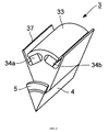
- Fig. 2 is a perspective view showing the configuration of one pole of the rotor 3.
- Fig. 3 is a front elevational view of the one pole of the rotor 3 seen from the direction of the rotation center axis 4a.
- Fig. 3 in addition to the configuration of the one pole, the configurations of the two neighboring poles in the direction of rotation of the one pole are shown by broken lines in order to facilitate understanding of the configuration of the rotor 3.
- the rotor 3 can be broadly divided into a core portion 31 toward the rotation center axis 4a, two permanent magnets 34a and 34b provided in each pole, an outer peripheral edge portion 33 of each pole formed of the rotor steel on the outer side of the permanent magnets 34a and 34b as seen from the rotation center axis 4a, a center bridge 32 of each pole, formed between magnet embedding holes 35a and 35b, that links the core portion 31 and outer peripheral edge portion 33, and a q-axis projection 37 provided between poles.
- the outer peripheral edge portion 33 of the one pole has an approximately arc-shaped sectional form, and is linked via the center bridge 32 to the core portion 31 in the center in the rotor rotation direction.
- the outer peripheral surface of the outer peripheral edge portion 33 has a radius of curvature smaller than the distance from the rotation center axis 4a to the outermost peripheral portion of the rotor. In this way, the radius of curvature of one portion of the outer peripheral edge portion 33, rather than that of the whole of the outer peripheral edge portion 33, may be smaller than the distance from the rotation center axis 4a to the outermost peripheral portion of the rotor.
- the outer peripheral surface of the outer peripheral edge portion 33 is curved, it is sufficient that the outer peripheral surface of the outer peripheral edge portion 33 positioned on an extension line passing through the center bridge 32 as seen from the center of rotation of the rotor is farther from the center of rotation of the rotor than the outer peripheral surface in other positions.
- the torque of the permanent magnet embedded-type rotating electric machine can be increased by increasing the magnetic resistance of the center bridge 32 and reducing the magnetic resistance of a stator disposed on the outer periphery of the rotor and the outer peripheral edge portion 33.
- the harmonic component of the torque is reduced, and the fundamental component of the torque generated in the rotor 3 can be increased by the amount of the reduction.
- the magnet embedding hole 35a, for holding the permanent magnet 34a, and the magnet embedding hole 35b, for holding the permanent magnet 34b, are provided on the inner side of the outer peripheral edge portion 33.
- the magnet embedding holes 35a and 35b are enclosed from three directions by the outer peripheral edge portion 33, center bridge 32, and core portion 31.
- the outer peripheral edge portion 33 supports the permanent magnets 34a and 35b on the rotation center axis 4a side against the centrifugal force acting on the permanent magnets 34a and 34b when the rotor 3 rotates.
- the outer peripheral edge portions 33 corresponding to each pole are aligned in the rotor rotation direction, maintaining a gap from the neighboring outer peripheral edge portions 33.
- the gap between two outer peripheral edge portions 33 is positioned on the side opposite to that of the center bridge 32, that is, halfway between the poles.
- the magnet embedding holes 35a and 35b communicate with the outer periphery of the rotor via the gap between the two outer peripheral edge portions 33.
- there is no gap between two outer peripheral edge portions 33 in existing, publicly-known general rotors there are many that have a side bridge connecting two outer peripheral edge portions 33.
- One characteristic of the rotor 3 shown in Fig. 2 and Fig. 3 is that this side bridge is omitted.
- the magnet embedding holes 35a and 35b are arrayed in a reverse V-shape. Further, a region (the core portion 31) on the rotation center axis 4a side of the inner peripheral walls of the magnet embedding holes 35a and 35b is inclined in a direction such as to become farther from the rotation center axis 4a as it moves away from halfway between neighboring poles and nears a region between the two magnet embedding holes (that is, the center bridge 32). Therefore, the center bridge 32 is in a position distanced outwardly in the rotor radial direction from an inscribed circle 36 of all the magnet embedding holes 35a and 35b of the rotor 3.
- the q-axis projection 37 passes through the gap between two outer peripheral edge portions 33 in a position on the core portion 31 halfway between poles, projecting in a centrifugal direction (a direction away from the rotation center axis 4a).
- Positioning projections 38a and 38b that regulate movement of the permanent magnets 34a and 34b to the q-axis projection 37 side are provided in the magnet embedding holes 35a and 35b.
- the positioning projections 38a and 38b protrude toward the rotation center axis 4a in a region of the inner walls of the magnet embedding holes 35a and 35b on the outer side in the rotor radial direction as seen from the permanent magnets 34a and 34b, that is, in an end portion on the q-axis projection 37 side on the inner side of the outer peripheral edge portion 33.
- the permanent magnets 34a and 34b are pressed against the positioning projections 38a and 38b, and thereby fixed inside the magnet embedding holes 35a and 35b.
- a pair of end plates (not shown) are provided one at either end in the axial direction of the rotor 3 so that the permanent magnets 34a and 34b do not fall out in the axial direction.
- the reason for the magnet embedding holes 35a and 35b being caused to communicate with the outer periphery of the rotor in the rotor 3 is as follows.
- a method whereby the shaft and rotor steel are assembled by an interference fitting such as shrink fitting is common.
- Tensile stress remains in the peripheral direction in the rotor steel in the interference fitting step. This remaining stress barely occurs on a circumference having the same radius as a portion wherein there is a hole, depression, or the like, in the rotor steel (that is, stress does not remain except in a portion that has no hole or depression and that is continuous in a ring form).
- a configuration wherein the magnet embedding holes 35a and 35b communicate with the outer periphery of the rotor that is, a configuration wherein there is no side bridge
- the rotor configuration As the rotor has no side bridge on the outermost periphery thereof, no residual assembly stress remains on the outermost periphery of the rotor. Stress generated by the centrifugal force when the rotor rotates concentrates on the center bridge, but as the stress acting on the center bridge is tensile stress, damage to the center bridge can easily be prevented by adjusting the width of the center bridge, or the like.
- the reinforcement sheets of the permanent magnets 34a and 34b are in a state of not being attached to the inner walls of the magnet embedding holes 35a and 35b, and can slide against the inner walls. This is the major characteristic of the invention.
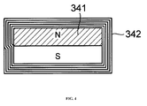
- Fig. 4 is a front elevational view showing the configuration of a permanent magnet 341 and reinforcement sheet 342 inserted into the magnet embedding holes 35a and 35b (refer to Fig. 2 and Fig. 3 ) of the rotor 3 in a first embodiment of the invention.
- FRP fiber-reinforced plastic
- the thickness of one turn of the reinforcement sheet 342 is in the region of 80 ⁇ m.
- the reinforcement sheet 342 and permanent magnet 341 are heated in a state wherein the reinforcement sheet 342 is wound around, thereby thermally hardening the reinforcement sheet 342 and causing the reinforcement sheet 342 to adhere to the surface of the permanent magnet 341.
- An FRP wherein epoxy is used as the plastic and glass fiber used as the fiber is applied as the FRP.
- the permanent magnet 341 to which the reinforcement sheet 342 is adhering is inserted in the magnet embedding holes 35a and 35b of the rotor 3, the permanent magnet 341 can be made less likely to crack when inserting. Also, in this embodiment, the surface of the reinforcement sheet 342 adhering to the permanent magnet 341 is in a state of not being attached to the inner wall of the magnet embedding hole 35a or 35b, and is slidable.
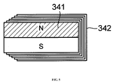
- Fig. 5 is a front elevational view showing the configuration of the permanent magnet 341 and reinforcement sheet 342 inserted into the magnet embedding holes 35a and 35b of the rotor 3 in a second embodiment of the invention.
- the reinforcement sheet 342 are wound around four surfaces, including the magnetized surfaces, of the permanent magnet 341, but in this embodiment, five turns of the reinforcement sheet 342 are wound around three surfaces, which are the two magnetized surfaces and one non-magnetized surface. That is, in this embodiment, the reinforcement sheet 342 is not adhering to one non-magnetized surface of the four surfaces on the periphery of the permanent magnet 341.
- the permanent magnet 341 when embedding the permanent magnet 341 in the rotor 3, the permanent magnet 341 is inserted in the magnet embedding hole 35a or 35b so that the non-magnetized surface of the permanent magnet 341 to which the reinforcement sheet 342 is not adhering is on the center bridge 32 side.
- the non-magnetized surface covered by the reinforcement sheet 342, of the four surfaces on the periphery of the permanent magnet 341 is aligned with the gap causing the magnet embedding hole 35a or 35b to communicate with the outer periphery of the rotor 3.
- the reinforcement sheet 342 is wound around only three surfaces of the permanent magnet 341, because of which the process of winding the reinforcement sheet 342 around the permanent magnet 341 can be carried out more easily than in the first embodiment, wherein the reinforcement sheet 342 is wound around four surfaces.
- Fig. 6 is a front elevational view showing the configuration of the permanent magnet 341 and reinforcement sheet 342 inserted into the magnet embedding holes 35a and 35b of the rotor 3 in a third embodiment of the invention.
- the second embodiment Fig. 5
- five turns of the reinforcement sheet 341 are wound around the two magnetized surfaces and one non-magnetized surface of the permanent magnet 341, but in this embodiment, one turn of the reinforcement sheet 341 is wound around the two magnetized surfaces and one non-magnetized surface of the permanent magnet 341.
- an end portion of the reinforcement sheet 341 juts out slightly from the two magnetized surfaces of the permanent magnet 341, bends, and adheres to the non-magnetized surface.
- the FRP used as the reinforcement sheet 341 is such that the adhesive strength between turns of the FRP when multiple turns are wound is high, but the adhesive strength between the FRP and permanent magnet 341 is low. Therefore, in this embodiment, the adhesive strength between the FRP and permanent magnet 341 is increased by attaching the FRP to the surface of the permanent magnet 341 by, for example, pressing the FRP against the surface of the permanent magnet 341 using a large winding force, and thermally hardening the FRP.
- the permanent magnet 341 when embedding the permanent magnet 341 in the rotor 3, the permanent magnet 341 is inserted in the magnet embedding hole 35a or 35b so that the non-magnetized surface of the permanent magnet 341 to which the reinforcement sheet 342 is not adhering is on the center bridge 32 side.
- the reinforcement sheet 342 sandwiched between the magnetized surfaces of the permanent magnet 341 and the inner wall surface of the magnet embedding hole 35a or 35b has only one turn of thickness. Consequently, the magnetic flux density between the magnetized surfaces of the permanent magnet 341 and the inner wall surface of the magnet embedding hole 35a or 35b can be increased, and a large torque can be generated in the rotor 3 by a small scale permanent magnet 341. Also, in this embodiment, an end portion of the reinforcement sheet 341 juts out slightly from the two magnetized surfaces of the permanent magnet 341, bends, and adheres to the non-magnetized surface.
- the reinforcement sheet 342 covers corner portions on the boundaries between the magnetized surfaces and non-magnetized surface of the permanent magnet 341. Consequently, the corner portions on the boundaries between the magnetized surfaces and non-magnetized surface of the permanent magnet 341 can be prevented from colliding directly with the inner wall of the magnet embedding hole 35a or 35b, and cracking of the permanent magnet 341 can thus be prevented.
- Fig. 7 is a front elevational view showing the configuration of the permanent magnet 341 and reinforcement sheet 342 inserted into the magnet embedding holes 35a and 35b of the rotor 3 in a fourth embodiment of the invention.
- a chamfering process is added to the left surface in accordance with the form of the inner wall of the magnet embedding hole 35a or 35b.
- the permanent magnet 341 when embedding the permanent magnet 341 in the rotor 3, the permanent magnet 341 is inserted in the magnet embedding hole 35a or 35b so that the chamfered non-magnetized surface of the permanent magnet 341 to which the reinforcement sheet 342 is not adhering is on the center bridge 32 side.
- the permanent magnet 341 and reinforcement sheet 342 are inserted into the kind of rounded magnet embedding hole 35a or 35b shown as an example in Fig. 3
- the chamfered, rounded reinforcement sheet 342 comes into contact with the inner wall of the magnet embedding hole 35a or 35b.
- a process of removing four turns is added to the top and bottom two surfaces of the reinforcement sheet 342 in Fig. 7 , whereby the thickness of the reinforcement sheet 342 between the magnetized surfaces of the permanent magnet 341 and the inner wall of the magnet embedding hole 35a or 35b is that of one turn. Consequently, in the same way as in the third embodiment, the magnetic flux density between the magnetized surfaces of the permanent magnet 341 and the inner wall surface of the magnet embedding hole 35a or 35b can be increased, and a large torque can be generated in the rotor 3 by a small scale permanent magnet 341.
- Fig. 8 is a front elevational view showing the configuration of the permanent magnet 341, the reinforcement sheet 342, and a spacer 343 inserted into the magnet embedding holes 35a and 35b of the rotor 3 in a fifth embodiment of the invention.
- the reinforcement sheet 342 of the same aspect as in the fourth embodiment is caused to adhere to the permanent magnet 341, but the non-magnetic and non-conductive spacer 343 formed of nylon or the like is provided on the inner side of the first turn of the reinforcement sheet 342.
- the nylon spacer 343 is attached and fixed in advance to the left end of the permanent magnet 341, after which the reinforcement sheet 341 formed of FRP is wrapped around and thermally hardened, and the same FRP chamfering and removal processes as in the fourth embodiment are carried out.
- the spacer 343 may be fixed to the permanent magnet 341 with a fixture such as a screw.
- the permanent magnet 341 when embedding the permanent magnet 341 in the rotor 3, the permanent magnet 341 is inserted in the magnet embedding hole 35a or 35b so that the non-magnetized surface of the permanent magnet 341 to which the spacer 343 is fixed is on the center bridge 32 side.
- the reinforcement sheet 342 can be pressed against the inner wall of the magnet embedding hole 35a or 35b by the spacer 343. Consequently, the number of turns, and the extent of the removal process, of the reinforcement sheet 342 can both be reduced, which is economical.
- the thickness of the reinforcement sheet 342 between the magnetized surfaces of the permanent magnet 341 and the inner wall of the magnet embedding hole 35a or 35b is that of one turn, in the same way as in the fourth embodiment. Consequently, the magnetic flux density between the magnetized surfaces of the permanent magnet 341 and the inner wall surface of the magnet embedding hole 35a or 35b can be increased, and a large torque can be generated in the rotor 3 by a small scale permanent magnet 341.
- FRP stacked in advance may also be used as the material of the spacer 343.
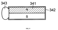
- Fig. 9 is a front elevational view showing the configuration of the permanent magnet 341, reinforcement sheet 342, and spacer 343 inserted into the magnet embedding holes 35a and 35b of the rotor 3 in a sixth embodiment of the invention.
- the configurations of the permanent magnet 341 and reinforcement sheet 342 are the same as in the third embodiment ( Fig. 6 ).
- the spacer 343 formed of nylon or the like is fixed to the non-magnetized surface of the permanent magnet 341 to which the reinforcement sheet 342 is not adhering.
- the spacer 343 may be fixed to the permanent magnet 341 with an adhesive, or may be fixed to the permanent magnet 341 with fixtures such as screws.
- FRP stacked in advance may also be used as the material of the spacer 343.
- the permanent magnet 341 when embedding the permanent magnet 341 in the rotor 3, the permanent magnet 341 is inserted in the magnet embedding hole 35a or 35b so that the non-magnetized surface of the permanent magnet 341 to which the spacer 343 is fixed is on the center bridge 32 side.
- the same advantages as in the fifth embodiment are obtained.
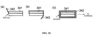
- Fig. 10 shows one portion of a permanent magnet embedded-type rotating electric machine manufacturing process, which is a seventh embodiment of the invention.
- this embodiment relates in particular to the step of fixing the reinforcement sheet 342 formed of FRP to the permanent magnet 341.
- This embodiment is preferred for fixing the reinforcement sheet 342 to four surfaces of the permanent magnet 341, as in, for example, the first embodiment ( Fig. 4 ), fourth embodiment ( Fig. 7 ), and fifth embodiment ( Fig. 8 ).
- the end portion of the reinforcement sheet 342 is fixed to one surface (the left side non-magnetized surface in the example shown in Fig. 10(a) ) on the periphery of the permanent magnet 341, the end portion is thermally hardened by being locally heated, and thereby fixed to the permanent magnet 341, as shown in Fig. 10(a) .
- the reinforcement sheet 342 is wrapped around the periphery of the permanent magnet 341, as shown in Fig. 10 (b) .
- the adhesive strength of the reinforcement sheet 342 with respect to the permanent magnet 341, and the adhesive strength between the turns of the reinforcement sheet 342, can be increased by the tension applied to the reinforcement sheet 342 being sufficiently high when wrapping the reinforcement sheet 342 around the permanent magnet 341.
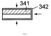
- Fig. 11 shows one portion of a permanent magnet embedded-type rotating electric machine manufacturing process, which is an eighth embodiment of the invention.
- this embodiment relates to the step of fixing the reinforcement sheet 342 formed of FRP to the permanent magnet 341.
- This embodiment is preferred for fixing the reinforcement sheet 342 to the permanent magnet 341 as in, for example, the second embodiment ( Fig. 5 ), third embodiment ( Fig. 6 ), and sixth embodiment ( Fig. 9 ).
- the reinforcement sheet 342 in a state wherein the desired number of turns (one turn in the example shown in Fig. 11 ) of the reinforcement sheet 342 are brought into contact with the desired surfaces (the upper, lower, and right three surfaces in the example shown in Fig. 11 ) of the permanent magnet 341, as shown in Fig. 11 , the reinforcement sheet 342 is pressed toward the permanent magnet 341, and the reinforcement sheet 342 and permanent magnet 341 are heated in this state, thereby thermally hardening the reinforcement sheet 342.
- the adhesive strength of the reinforcement sheet 342 with respect to the permanent magnet 341, and the adhesive strength between the turns of the reinforcement sheet 342 (when a multiple of turns of the reinforcement sheet 342 are fixed to the permanent magnet 341), can be increased by the force pressing the reinforcement sheet 342 against the permanent magnet 341 being sufficiently large.
- the reinforcement sheet 342 is caused to adhere to the permanent magnet 341 and embedded in the magnet embedding hole 35a or 35b, because of which the permanent magnet 341 can be made unlikely to crack. Also, even when the permanent magnet 341 cracks, the magnet and fragments can be prevented from separating. Also, according to each embodiment of the invention, the surface of the reinforcement sheet 342 adhering to the permanent magnet 341 and the inner wall of the magnet embedding hole 35a or 35b are in a state of not being attached in a state wherein the permanent magnet 341 is embedded in the magnet embedding hole 35a or 35b.
- the surface of the reinforcement sheet 342 and the inner wall of the magnet embedding hole 35a or 35b are in a state of not being attached, but they may also be in a low elasticity attachment state such that there is no cracking of the magnet due to thermal stress caused by the difference between the linear expansion rates of the rotor 3 and permanent magnet 341.
- each embodiment of the invention it is possible to realize a permanent magnet embedded-type rotating electric machine such that a permanent magnet having characteristics such that the magnet intrinsically cracks easily can be used stably over a long period. Furthermore, by thermally hardening the reinforcement sheet 342, thereby causing the reinforcement sheet 342 to adhere to the material of the permanent magnet 341, and subsequently carrying out magnetization of the material of the permanent magnet 341, demagnetization due to high temperature when thermally hardening the reinforcement sheet 342 is eliminated. Also, according to each embodiment of the invention, it is possible to provide a permanent magnet embedded-type rotating electric machine that, for that kind of permanent magnet embedded-type rotating electric machine, is small, low cost, and easily maintained.
Landscapes
- Engineering & Computer Science (AREA)
- Power Engineering (AREA)
- Manufacturing & Machinery (AREA)
- Permanent Field Magnets Of Synchronous Machinery (AREA)
- Manufacture Of Motors, Generators (AREA)
- Iron Core Of Rotating Electric Machines (AREA)
- Permanent Magnet Type Synchronous Machine (AREA)
Abstract
Description
- The present invention relates to a rotating electric machine having a rotor, such as a motor or generator, and in particular, relates to a permanent magnet embedded-type rotating electric machine wherein permanent magnets are embedded in the rotor.
- In this kind of permanent magnet embedded-type rotating electric machine, the permanent magnets are inserted into magnet embedding holes formed in the rotor. The permanent magnets are a member that cracks comparatively easily. However, when the permanent magnets crack and divide, the performance of the permanent magnet embedded-type rotating electric machine depreciates. Also, depending on the way in which the permanent magnets crack, the magnets move inside the magnet embedding holes. Further, when movement of the magnets starts, the magnets collide with the inner wall of the magnet embedding holes, and occasions for the magnets to crack increase further. Also, when the magnets move inside the magnet embedding holes, there is a danger of the rotor balance breaking down, and rotor vibration increasing due to the effect of centrifugal force acting on the rotor.
- PTL 1:
JP-A-9-163649 -
PTL 1 exists as technical literature disclosing technology whereby cracking of permanent magnets in a permanent magnet embedded-type rotating electric machine is prevented. The technology disclosed inPTL 1 is such that permanent magnets on an outer peripheral portion of which is disposed adhesive sheets impregnated or coated with an adhesive is inserted into a rotor magnet embedding holes. By so doing, cracking of the permanent magnets when inserting can be prevented. However, the technology disclosed inPTL 1 is such that the permanent magnets are attached and fixed to the inner wall of the rotor magnet embedding holes by the adhesive sheets. Herein, the linear expansion coefficients of the permanent magnets and rotor steel differ. Consequently, when a state wherein the permanent magnets are attached and fixed to the inner wall of the rotor magnet embedding holes exists, there is a problem in that excessive stress caused by the difference between the linear expansion rates of the rotor and permanent magnets are exerted on the permanent magnets when, for example, the temperature of the rotor rises due to operation of the rotating electric machine, and cracking occurs in the permanent magnets. - The invention, having been contrived with the heretofore described kind of situation in mind, has an object of providing technological means whereby cracking of permanent magnets in a permanent magnet embedded-type rotating electric machine is prevented, not only when the permanent magnets are embedded in a rotor, but also after the embedding.
- The invention provides a permanent magnet embedded-type rotating electric machine, formed by permanent magnets to which reinforcement sheets are adhering being embedded in magnet embedding holes formed in the circumferential direction in a rotor, wherein the surface of the reinforcement sheets are in a state of not being attached to the inner wall surface of the magnet embedding holes.
- According to the invention, reinforcement sheets are adhering to permanent magnets embedded in magnet embedding holes of a rotor. Consequently, cracking of the permanent magnets can be prevented. Also, according to the invention, the surface of the reinforcement sheets embedded in the magnet embedding holes of the rotor is in a state of not being attached to the inner wall surface of the magnet embedding holes. Therefore, it is possible to avoid a situation wherein stress caused by the difference between the linear expansion coefficients of the rotor and permanent magnets acts on the permanent magnets when, for example, the temperature of the rotor rises due to an operation of the permanent magnet embedded-type rotating electric machine, and thus possible to prevent cracking of the permanent magnets.
-
- [
Fig. 1] Fig. 1 is a vertical sectional view showing a configuration of a permanent magnet embedded-type rotating electric machine, which is an application of the invention. - [
Fig. 2] Fig. 2 is a perspective view showing the configuration of one pole of a rotor of the same permanent magnet embedded-type rotating electric machine. - [
Fig. 3] Fig. 3 is a front elevational view showing the configuration of one pole of a rotor of the same permanent magnet embedded-type rotating electric machine. - [
Fig. 4] Fig. 4 is a front elevational view showing the configuration of permanent magnets and reinforcement sheets embedded in magnet embedding holes of the rotor in a first embodiment of the invention. - [
Fig. 5] Fig. 5 is a front elevational view showing the configuration of the permanent magnets and reinforcement sheets embedded in the magnet embedding holes of the rotor in a second embodiment of the invention. - [
Fig. 6] Fig. 6 is a front elevational view showing the configuration of the permanent magnets and reinforcement sheets embedded in the magnet embedding holes of the rotor in a third embodiment of the invention. - [
Fig. 7] Fig. 7 is a front elevational view showing the configuration of the permanent magnets and reinforcement sheets embedded in the magnet embedding holes of the rotor in a fourth embodiment of the invention. - [
Fig. 8] Fig. 8 is a front elevational view showing the configuration of the permanent magnets, reinforcement sheets and spacers embedded in the magnet embedding holes of the rotor in a fifth embodiment of the invention. - [
Fig. 9] Fig. 9 is a front elevational view showing the configuration of the permanent magnets, reinforcement sheets and spacer embedded in the magnet embedding holes of the rotor in a sixth embodiment of the invention. - [
Fig. 10] Fig. 10 is a diagram showing steps of manufacturing permanent magnets to which reinforcement sheets are adhering in a seventh embodiment of the invention. - [
Fig. 11] Fig. 11 is a diagram showing a step of manufacturing permanent magnets to which reinforcement sheets are adhering in an eighth embodiment of the invention. - [
Fig. 12] Fig. 12 is a diagram showing steps of manufacturing permanent magnets to which reinforcement sheets are adhering in another embodiment of the invention. - Hereafter, referring to the drawings, a description will be given of embodiments of the invention.
-
Fig. 1 is a vertical sectional view showing a configuration example of a permanent magnet embedded-type rotating electric machine, which is an application of the invention. InFig. 1 ,frame 1 is a housing body that covers the whole of the permanent magnet embedded-type rotating electric machine, and is configured of iron, aluminum, stainless steel, or the like. A hollow, cylindrical fixedside iron core 2 is provided on the inner side of theframe 1. The fixedside iron core 2 is formed by stacking silicon steel plates. A multiple of teeth are formed on the fixedside iron core 2, and a stator coil formed of copper wire or the like is wound around each tooth (omitted from the drawing). Arotor 3, which is a rotating side iron core, is inserted on the inner side of the fixedside iron core 2, in a state maintaining a predetermined gap from the fixedside iron core 2. Therotor 3 is formed by stacking silicon steel plates. There are also cases in which therotor 3 is configured by carrying out a cutting process on a simple iron block. Ashaft 4 formed of iron or the like penetrates the center of therotor 3. Ideally, the central axis of theshaft 4 forms arotation center axis 4a of therotor 3. Further, theshaft 4 is supported by ashield 6 provided at either front-back end of theframe 1, via a rollingbearing 5 formed of bearing steel or the like. - Herein, a description will be given with a motor as an example of a permanent magnet embedded-type rotating electric machine, but the same applies in the case of a generator. In the motor, the
rotor 3 is provided with energy by a rotating magnetic field created by stator coils (not shown), and rotates around therotation center axis 4a. -
Fig. 2 is a perspective view showing the configuration of one pole of therotor 3. Also,Fig. 3 is a front elevational view of the one pole of therotor 3 seen from the direction of therotation center axis 4a. InFig. 3 , in addition to the configuration of the one pole, the configurations of the two neighboring poles in the direction of rotation of the one pole are shown by broken lines in order to facilitate understanding of the configuration of therotor 3. - The
rotor 3 can be broadly divided into acore portion 31 toward therotation center axis 4a, twopermanent magnets peripheral edge portion 33 of each pole formed of the rotor steel on the outer side of thepermanent magnets rotation center axis 4a, acenter bridge 32 of each pole, formed betweenmagnet embedding holes core portion 31 and outerperipheral edge portion 33, and a q-axis projection 37 provided between poles. - The outer
peripheral edge portion 33 of the one pole has an approximately arc-shaped sectional form, and is linked via thecenter bridge 32 to thecore portion 31 in the center in the rotor rotation direction. The outer peripheral surface of the outerperipheral edge portion 33 has a radius of curvature smaller than the distance from therotation center axis 4a to the outermost peripheral portion of the rotor. In this way, the radius of curvature of one portion of the outerperipheral edge portion 33, rather than that of the whole of the outerperipheral edge portion 33, may be smaller than the distance from therotation center axis 4a to the outermost peripheral portion of the rotor. Also, it not being necessary that the outer peripheral surface of the outerperipheral edge portion 33 is curved, it is sufficient that the outer peripheral surface of the outerperipheral edge portion 33 positioned on an extension line passing through thecenter bridge 32 as seen from the center of rotation of the rotor is farther from the center of rotation of the rotor than the outer peripheral surface in other positions. In this way, the torque of the permanent magnet embedded-type rotating electric machine can be increased by increasing the magnetic resistance of thecenter bridge 32 and reducing the magnetic resistance of a stator disposed on the outer periphery of the rotor and the outerperipheral edge portion 33. By adopting this kind of form for the outerperipheral edge portion 33, the harmonic component of the torque is reduced, and the fundamental component of the torque generated in therotor 3 can be increased by the amount of the reduction. - The
magnet embedding hole 35a, for holding thepermanent magnet 34a, and themagnet embedding hole 35b, for holding thepermanent magnet 34b, are provided on the inner side of the outerperipheral edge portion 33. Themagnet embedding holes peripheral edge portion 33,center bridge 32, andcore portion 31. The outerperipheral edge portion 33 supports thepermanent magnets rotation center axis 4a side against the centrifugal force acting on thepermanent magnets rotor 3 rotates. The outerperipheral edge portions 33 corresponding to each pole are aligned in the rotor rotation direction, maintaining a gap from the neighboring outerperipheral edge portions 33. The gap between two outerperipheral edge portions 33 is positioned on the side opposite to that of thecenter bridge 32, that is, halfway between the poles. Themagnet embedding holes peripheral edge portions 33. As there is no gap between two outerperipheral edge portions 33 in existing, publicly-known general rotors, there are many that have a side bridge connecting two outerperipheral edge portions 33. One characteristic of therotor 3 shown inFig. 2 andFig. 3 is that this side bridge is omitted. - The
magnet embedding holes rotation center axis 4a side of the inner peripheral walls of themagnet embedding holes rotation center axis 4a as it moves away from halfway between neighboring poles and nears a region between the two magnet embedding holes (that is, the center bridge 32). Therefore, thecenter bridge 32 is in a position distanced outwardly in the rotor radial direction from an inscribedcircle 36 of all themagnet embedding holes rotor 3. - The q-
axis projection 37 passes through the gap between two outerperipheral edge portions 33 in a position on thecore portion 31 halfway between poles, projecting in a centrifugal direction (a direction away from therotation center axis 4a).Positioning projections permanent magnets axis projection 37 side are provided in themagnet embedding holes positioning projections rotation center axis 4a in a region of the inner walls of themagnet embedding holes permanent magnets axis projection 37 side on the inner side of the outerperipheral edge portion 33. Thepermanent magnets positioning projections magnet embedding holes rotor 3 so that thepermanent magnets - The above is the configuration of the
rotor 3. - The reason for the
magnet embedding holes rotor 3 is as follows. In manufacturing the motor, a method whereby the shaft and rotor steel are assembled by an interference fitting such as shrink fitting is common. Tensile stress remains in the peripheral direction in the rotor steel in the interference fitting step. This remaining stress barely occurs on a circumference having the same radius as a portion wherein there is a hole, depression, or the like, in the rotor steel (that is, stress does not remain except in a portion that has no hole or depression and that is continuous in a ring form). - Meanwhile, an enormous centrifugal force is generated in each portion of the rotor when the
rotor 3 rotates at high speed. At this time, when the rotor has a center bridge and a side bridge, large stress is generated in the center bridge and side bridge. In this case, due to the centrifugal force generated by the rotation of the rotor, tensile stress acts on the center bridge while shearing stress acts on the side bridge. Therefore, in order to prevent damage to the rotor due to high speed rotation, it is necessary to sufficiently strengthen the side bridge rather than the center bridge, which point makes the rotor strength design difficult. Therefore, in this example, a configuration wherein themagnet embedding holes - However, as the heretofore described permanent magnet embedded-type rotating electric machine has no side bridge, and the
magnet embedding holes magnet embedding holes permanent magnet permanent magnets magnet embedding holes permanent magnets magnet embedding holes permanent magnets magnet embedding holes -
Fig. 4 is a front elevational view showing the configuration of apermanent magnet 341 andreinforcement sheet 342 inserted into themagnet embedding holes Fig. 2 andFig. 3 ) of therotor 3 in a first embodiment of the invention. In the example, five turns of FRP (fiber-reinforced plastic) are wound as thereinforcement sheet 342 around four surfaces, including the magnetized surfaces (the surfaces on which is the N pole or S pole of the permanent magnet), of thepermanent magnet 341. Herein, the thickness of one turn of thereinforcement sheet 342 is in the region of 80µm. Thereinforcement sheet 342 andpermanent magnet 341 are heated in a state wherein thereinforcement sheet 342 is wound around, thereby thermally hardening thereinforcement sheet 342 and causing thereinforcement sheet 342 to adhere to the surface of thepermanent magnet 341. An FRP wherein epoxy is used as the plastic and glass fiber used as the fiber is applied as the FRP. By using epoxy having hardening conditions such that the hardening temperature of the plastic does not exceed the Curie temperature of the permanent magnet, the magnetic characteristics of the permanent magnet can be prevented from changing when carrying out thermal hardening. When the temperature drops after thermal hardening, the surface of thereinforcement sheet 342 dries, reaching a state wherein there is no adhesive action. In this state, thepermanent magnet 341 to which thereinforcement sheet 342 is adhering is inserted in themagnet embedding holes rotor 3, and magnetization of thepermanent magnet 341 is carried out. - According to this embodiment, as the
permanent magnet 341 to which thereinforcement sheet 342 is adhering is inserted in themagnet embedding holes rotor 3, thepermanent magnet 341 can be made less likely to crack when inserting. Also, in this embodiment, the surface of thereinforcement sheet 342 adhering to thepermanent magnet 341 is in a state of not being attached to the inner wall of themagnet embedding hole rotor 3 andpermanent magnet 341 acts on thepermanent magnet 341, thus preventing cracking of thepermanent magnet 341, when the permanent magnet embedded-type rotating electric machine is operating, even when, for example, the temperature of therotor 3 rises. Also, this configuration is such that, even in the event that thepermanent magnet 341 cracks, fragments are unlikely to separate, and there is unlikely to be the kind of situation wherein thepermanent magnet 341 moves inside themagnet embedding hole -
Fig. 5 is a front elevational view showing the configuration of thepermanent magnet 341 andreinforcement sheet 342 inserted into themagnet embedding holes rotor 3 in a second embodiment of the invention. In the first embodiment, five turns of thereinforcement sheet 342 are wound around four surfaces, including the magnetized surfaces, of thepermanent magnet 341, but in this embodiment, five turns of thereinforcement sheet 342 are wound around three surfaces, which are the two magnetized surfaces and one non-magnetized surface. That is, in this embodiment, thereinforcement sheet 342 is not adhering to one non-magnetized surface of the four surfaces on the periphery of thepermanent magnet 341. - In this embodiment, when embedding the
permanent magnet 341 in therotor 3, thepermanent magnet 341 is inserted in themagnet embedding hole permanent magnet 341 to which thereinforcement sheet 342 is not adhering is on thecenter bridge 32 side. By so doing, the non-magnetized surface covered by thereinforcement sheet 342, of the four surfaces on the periphery of thepermanent magnet 341, is aligned with the gap causing themagnet embedding hole rotor 3. Consequently, cracking of thepermanent magnet 341 on this non-magnetized surface can be prevented, and fragments of thepermanent magnet 341 can be prevented from flying toward the outer periphery of therotor 3. Also, according to this configuration, even in the event that cracking of thepermanent magnet 341 occurs on the non-magnetized surface to which thereinforcement sheet 342 is not adhering, the main body of thepermanent magnet 341 impedes fragments of thepermanent magnet 341 attempting to leave themagnet embedding hole rotor 3. Consequently, flying of fragments of thepermanent magnet 341 to the outer periphery of therotor 3 can be prevented. Consequently, the same advantages as in the first embodiment can be obtained in this embodiment too. Also, in this embodiment, thereinforcement sheet 342 is wound around only three surfaces of thepermanent magnet 341, because of which the process of winding thereinforcement sheet 342 around thepermanent magnet 341 can be carried out more easily than in the first embodiment, wherein thereinforcement sheet 342 is wound around four surfaces. -
Fig. 6 is a front elevational view showing the configuration of thepermanent magnet 341 andreinforcement sheet 342 inserted into themagnet embedding holes rotor 3 in a third embodiment of the invention. In the second embodiment (Fig. 5 ), five turns of thereinforcement sheet 341 are wound around the two magnetized surfaces and one non-magnetized surface of thepermanent magnet 341, but in this embodiment, one turn of thereinforcement sheet 341 is wound around the two magnetized surfaces and one non-magnetized surface of thepermanent magnet 341. Also, in this embodiment, an end portion of thereinforcement sheet 341 juts out slightly from the two magnetized surfaces of thepermanent magnet 341, bends, and adheres to the non-magnetized surface. - Herein, the FRP used as the
reinforcement sheet 341 is such that the adhesive strength between turns of the FRP when multiple turns are wound is high, but the adhesive strength between the FRP andpermanent magnet 341 is low. Therefore, in this embodiment, the adhesive strength between the FRP andpermanent magnet 341 is increased by attaching the FRP to the surface of thepermanent magnet 341 by, for example, pressing the FRP against the surface of thepermanent magnet 341 using a large winding force, and thermally hardening the FRP. - In this embodiment too, when embedding the
permanent magnet 341 in therotor 3, thepermanent magnet 341 is inserted in themagnet embedding hole permanent magnet 341 to which thereinforcement sheet 342 is not adhering is on thecenter bridge 32 side. - In this embodiment too, the same advantages as in the first and second embodiments can be obtained. Also, in this embodiment, the
reinforcement sheet 342 sandwiched between the magnetized surfaces of thepermanent magnet 341 and the inner wall surface of themagnet embedding hole permanent magnet 341 and the inner wall surface of themagnet embedding hole rotor 3 by a small scalepermanent magnet 341. Also, in this embodiment, an end portion of thereinforcement sheet 341 juts out slightly from the two magnetized surfaces of thepermanent magnet 341, bends, and adheres to the non-magnetized surface. In this way, in this embodiment, thereinforcement sheet 342 covers corner portions on the boundaries between the magnetized surfaces and non-magnetized surface of thepermanent magnet 341. Consequently, the corner portions on the boundaries between the magnetized surfaces and non-magnetized surface of thepermanent magnet 341 can be prevented from colliding directly with the inner wall of themagnet embedding hole permanent magnet 341 can thus be prevented. -
Fig. 7 is a front elevational view showing the configuration of thepermanent magnet 341 andreinforcement sheet 342 inserted into themagnet embedding holes rotor 3 in a fourth embodiment of the invention. In this embodiment, after five turns of thereinforcement sheet 341 are wound around four surfaces, including the two magnetized surfaces, of thepermanent magnet 341 and thermally hardened, a chamfering process is added to the left surface in accordance with the form of the inner wall of themagnet embedding hole - In this embodiment, when embedding the
permanent magnet 341 in therotor 3, thepermanent magnet 341 is inserted in themagnet embedding hole permanent magnet 341 to which thereinforcement sheet 342 is not adhering is on thecenter bridge 32 side. By so doing, when thepermanent magnet 341 andreinforcement sheet 342 are inserted into the kind of roundedmagnet embedding hole Fig. 3 , the chamfered,rounded reinforcement sheet 342 comes into contact with the inner wall of themagnet embedding hole reinforcement sheet 342 inFig. 7 is small, the portion wherein thereinforcement sheet 342 comes into contact with the inner wall of themagnet embedding hole reinforcement sheet 342 inFig. 7 has a sufficiently large radial curvature, the shock of contact with the inner wall of themagnet embedding hole - Also, in this embodiment, a process of removing four turns is added to the top and bottom two surfaces of the
reinforcement sheet 342 inFig. 7 , whereby the thickness of thereinforcement sheet 342 between the magnetized surfaces of thepermanent magnet 341 and the inner wall of themagnet embedding hole permanent magnet 341 and the inner wall surface of themagnet embedding hole rotor 3 by a small scalepermanent magnet 341. -
Fig. 8 is a front elevational view showing the configuration of thepermanent magnet 341, thereinforcement sheet 342, and aspacer 343 inserted into themagnet embedding holes rotor 3 in a fifth embodiment of the invention. In this embodiment, thereinforcement sheet 342 of the same aspect as in the fourth embodiment is caused to adhere to thepermanent magnet 341, but the non-magnetic andnon-conductive spacer 343 formed of nylon or the like is provided on the inner side of the first turn of thereinforcement sheet 342. Specifically, in this embodiment, thenylon spacer 343 is attached and fixed in advance to the left end of thepermanent magnet 341, after which thereinforcement sheet 341 formed of FRP is wrapped around and thermally hardened, and the same FRP chamfering and removal processes as in the fourth embodiment are carried out. Instead of being attached and fixed to thepermanent magnet 341 with an adhesive, thespacer 343 may be fixed to thepermanent magnet 341 with a fixture such as a screw. - In this embodiment, when embedding the
permanent magnet 341 in therotor 3, thepermanent magnet 341 is inserted in themagnet embedding hole permanent magnet 341 to which thespacer 343 is fixed is on thecenter bridge 32 side. According to this embodiment, even when themagnet embedding hole permanent magnet 341, thereinforcement sheet 342 can be pressed against the inner wall of themagnet embedding hole spacer 343. Consequently, the number of turns, and the extent of the removal process, of thereinforcement sheet 342 can both be reduced, which is economical. - Also, in this embodiment too, the thickness of the
reinforcement sheet 342 between the magnetized surfaces of thepermanent magnet 341 and the inner wall of themagnet embedding hole permanent magnet 341 and the inner wall surface of themagnet embedding hole rotor 3 by a small scalepermanent magnet 341. FRP stacked in advance may also be used as the material of thespacer 343. -
Fig. 9 is a front elevational view showing the configuration of thepermanent magnet 341,reinforcement sheet 342, andspacer 343 inserted into themagnet embedding holes rotor 3 in a sixth embodiment of the invention. - In this embodiment, the configurations of the
permanent magnet 341 andreinforcement sheet 342 are the same as in the third embodiment (Fig. 6 ). In this embodiment, thespacer 343 formed of nylon or the like is fixed to the non-magnetized surface of thepermanent magnet 341 to which thereinforcement sheet 342 is not adhering. Thespacer 343 may be fixed to thepermanent magnet 341 with an adhesive, or may be fixed to thepermanent magnet 341 with fixtures such as screws. Also, FRP stacked in advance may also be used as the material of thespacer 343. - In this embodiment, when embedding the
permanent magnet 341 in therotor 3, thepermanent magnet 341 is inserted in themagnet embedding hole permanent magnet 341 to which thespacer 343 is fixed is on thecenter bridge 32 side. In this embodiment too, the same advantages as in the fifth embodiment are obtained. -
Fig. 10 shows one portion of a permanent magnet embedded-type rotating electric machine manufacturing process, which is a seventh embodiment of the invention. Of the steps of the permanent magnet embedded-type rotating electric machine manufacturing process, this embodiment relates in particular to the step of fixing thereinforcement sheet 342 formed of FRP to thepermanent magnet 341. This embodiment is preferred for fixing thereinforcement sheet 342 to four surfaces of thepermanent magnet 341, as in, for example, the first embodiment (Fig. 4 ), fourth embodiment (Fig. 7 ), and fifth embodiment (Fig. 8 ). - In this embodiment, firstly, in a state wherein an end portion of the
reinforcement sheet 342 is fixed to one surface (the left side non-magnetized surface in the example shown inFig. 10(a) ) on the periphery of thepermanent magnet 341, the end portion is thermally hardened by being locally heated, and thereby fixed to thepermanent magnet 341, as shown inFig. 10(a) . Next, while tension is applied to thereinforcement sheet 342, thereinforcement sheet 342 is wrapped around the periphery of thepermanent magnet 341, as shown inFig. 10 (b) . When thereinforcement sheet 342 is wrapped around the periphery of thepermanent magnet 341 for the necessary number of turns, one portion of thereinforcement sheet 342 is thermally hardened by being locally heated, and that portion is attached to an inner turn of thereinforcement sheet 342, as shown inFig. 10 (c) . Thereinforcement sheet 342 left over beyond the place of attachment is cut off. In this way, an object wherein the necessary number of turns of thereinforcement sheet 342 are wrapped around and fixed to the periphery of thepermanent magnet 341 is obtained. This object wherein the necessary number of turns of thereinforcement sheet 342 are wrapped around and fixed to the periphery of thepermanent magnet 341 is placed into a furnace and heated, whereby the whole of thereinforcement sheet 342 wrapped around thepermanent magnet 341 is thermally hardened, and thereby fixed to the periphery of thepermanent magnet 341. - According to this embodiment, the adhesive strength of the
reinforcement sheet 342 with respect to thepermanent magnet 341, and the adhesive strength between the turns of thereinforcement sheet 342, can be increased by the tension applied to thereinforcement sheet 342 being sufficiently high when wrapping thereinforcement sheet 342 around thepermanent magnet 341. -
Fig. 11 shows one portion of a permanent magnet embedded-type rotating electric machine manufacturing process, which is an eighth embodiment of the invention. In the same way as the seventh embodiment, this embodiment relates to the step of fixing thereinforcement sheet 342 formed of FRP to thepermanent magnet 341. This embodiment is preferred for fixing thereinforcement sheet 342 to thepermanent magnet 341 as in, for example, the second embodiment (Fig. 5 ), third embodiment (Fig. 6 ), and sixth embodiment (Fig. 9 ). - In this embodiment, in a state wherein the desired number of turns (one turn in the example shown in
Fig. 11 ) of thereinforcement sheet 342 are brought into contact with the desired surfaces (the upper, lower, and right three surfaces in the example shown inFig. 11 ) of thepermanent magnet 341, as shown inFig. 11 , thereinforcement sheet 342 is pressed toward thepermanent magnet 341, and thereinforcement sheet 342 andpermanent magnet 341 are heated in this state, thereby thermally hardening thereinforcement sheet 342. - According to this embodiment, the adhesive strength of the
reinforcement sheet 342 with respect to thepermanent magnet 341, and the adhesive strength between the turns of the reinforcement sheet 342 (when a multiple of turns of thereinforcement sheet 342 are fixed to the permanent magnet 341), can be increased by the force pressing thereinforcement sheet 342 against thepermanent magnet 341 being sufficiently large. - As heretofore described, according to each embodiment of the invention, the
reinforcement sheet 342 is caused to adhere to thepermanent magnet 341 and embedded in themagnet embedding hole permanent magnet 341 can be made unlikely to crack. Also, even when thepermanent magnet 341 cracks, the magnet and fragments can be prevented from separating. Also, according to each embodiment of the invention, the surface of thereinforcement sheet 342 adhering to thepermanent magnet 341 and the inner wall of themagnet embedding hole permanent magnet 341 is embedded in themagnet embedding hole permanent magnet 341 androtor 3 acts on thepermanent magnet 341 due to a rise in the temperature of therotor 3 when the permanent magnet embedded-type rotating electric machine is operating, and thus possible to prevent cracking of thepermanent magnet 341. Heretofore, it is taken that the surface of thereinforcement sheet 342 and the inner wall of themagnet embedding hole rotor 3 andpermanent magnet 341. Consequently, according to each embodiment of the invention, it is possible to realize a permanent magnet embedded-type rotating electric machine such that a permanent magnet having characteristics such that the magnet intrinsically cracks easily can be used stably over a long period. Furthermore, by thermally hardening thereinforcement sheet 342, thereby causing thereinforcement sheet 342 to adhere to the material of thepermanent magnet 341, and subsequently carrying out magnetization of the material of thepermanent magnet 341, demagnetization due to high temperature when thermally hardening thereinforcement sheet 342 is eliminated. Also, according to each embodiment of the invention, it is possible to provide a permanent magnet embedded-type rotating electric machine that, for that kind of permanent magnet embedded-type rotating electric machine, is small, low cost, and easily maintained. - Heretofore, a description has been given of embodiments of the invention, but other embodiments of the invention are also conceivable. These are, for example, as below.
- (1) In the heretofore described embodiments, the
reinforcement sheet 342 is wrapped around three surfaces or four surfaces of thepermanent magnet 341, but thereinforcement sheet 342 may also be wrapped around one surface, two surfaces, or five or more surfaces, of thepermanent magnet 341. - (2) In the heretofore described embodiments, a broadly six sided body is used as the form of the
permanent magnet 341, but permanent magnets of another form may also be used. - (3) In the fourth embodiment (
Fig. 7 ) and fifth embodiment (Fig. 8 ), R chamfering is carried out as the method of chamfering thereinforcement sheet 342, but C chamfering may also be carried out. - (4) In the heretofore described embodiments, the thermally hardening
reinforcement sheet 342 formed of FRP is used, but reinforcement sheets formed of another material may also be used. For example, thepermanent magnet 341 may be housed inside a tube-form reinforcement sheet 342 formed of a thermally contracting material, as shown inFig. 12(a) , and thereinforcement sheet 342 caused to contract by heating, thereby fixing thereinforcement sheet 342 to the periphery of thepermanent magnet 341, as shown inFig. 12(b) . - (5) In the heretofore described embodiments, the invention is applied to a rotor having no side bridge, but the invention may also be applied to a rotor having a side bridge.
- (6) In the heretofore described embodiments, the
reinforcement sheet 342 is caused to adhere to the material of a magnet by being thermally hardened, after which magnetization of the material is carried out to form thepermanent magnet 341, but thereinforcement sheet 342 may also be caused to adhere to a magnetizedpermanent magnet 341. -
- 3 ···· Rotor, 2 ···· Stator, 35a, 35b ···· magnet embedding hole, 34a, 34b, 341 ···· Permanent magnet, 342 ···· reinforcement sheet, 343 ···· Spacer
Claims (20)
- A permanent magnet embedded-type rotating electric machine, formed by permanent magnets to which reinforcement sheets are adhering being embedded in a magnet embedding holes formed in the circumferential direction in a rotor, wherein the surfaces of the reinforcement sheets are in a state of not being attached to the inner wall surface of the magnet embedding holes.
- The permanent magnet embedded-type rotating electric machine according to claim 1, wherein the reinforcement sheets are thermally hardened fiber-reinforced plastic sheets, formed by permanent magnets to the surface of which the fiber-reinforced plastic sheets are caused to adhere by thermal hardening being embedded in the magnet embedding hole.
- The permanent magnet embedded-type rotating electric machine according to claim 2, wherein the plastic hardening temperature of the fiber-reinforced plastic is a temperature that does not exceed the Curie temperature of the permanent magnets.
- The permanent magnet embedded-type rotating electric machine according to claim 1, formed by a removal process being added to one portion of the reinforcement sheets.
- The permanent magnet embedded-type rotating electric machine according to claim 1, formed by the reinforcement sheets being wrapped around the permanent magnets.
- The permanent magnet embedded-type rotating electric machine according to claim 5, wherein the reinforcement sheets are thermally hardened fiber-reinforced plastic sheets, formed by a permanent magnets to the surface of which the fiber-reinforced plastic sheets are caused to adhere by thermal hardening being embedded in the magnet embedding hole.
- The permanent magnet embedded-type rotating electric machine according to claim 5, wherein the number of wrapping turns of the reinforcement sheets is a plural number.
- The permanent magnet embedded-type rotating electric machine according to claim 5, formed by a removal process being added to one portion of the reinforcement sheets.
- The permanent magnet embedded-type rotating electric machine according to claim 5, wherein the number of wrapping turns of the reinforcement sheets is a plural number, a removal process is added to one portion of the reinforcement sheets, and one or more turns of the reinforcement sheets are left with no removal process being added.
- The permanent magnet embedded-type rotating electric machine according to claim 8, wherein a large amount of the reinforcement sheets adhering to a magnetized surface perpendicular to the permanent magnets magnetization direction is ground away, and a large amount of the reinforcement sheets adhering to a non-magnetized surface other than the magnetized surface is left.
- The permanent magnet embedded-type rotating electric machine according to claim 9, wherein a large amount of the reinforcement sheets adhering to a magnetized surface perpendicular to the permanent magnets magnetization direction is ground away, and a large amount of the reinforcement sheets adhering to a non-magnetized surface other than the magnetized surface is left.
- The permanent magnet embedded-type rotating electric machine according to claim 1, formed by a non-magnetic and non-conductive spacers being added to the permanent magnets, and the reinforcement sheets being wrapped around the permanent magnets and spacers.
- The permanent magnet embedded-type rotating electric machine according to claim 12, formed by the spacers being fixed to the permanent magnets by adhesion or a fixture such as a screw, and the reinforcement sheets being wrapped around.
- The permanent magnet embedded-type rotating electric machine according to claim 1, formed by a non-magnetic and non-conductive spacers being added to a permanent magnets to which the reinforcement sheets are adhering.
- The permanent magnet embedded-type rotating electric machine according to any one of claims 1 to 14, wherein the rotor is such that a center bridge is formed between the magnet embedding holes, the magnet embedding holes communicate with the outer periphery of the rotor on the side opposite to that of the center bridge, and the center bridge is positioned outwardly in the rotor radial direction from an inscribed circle of the magnet embedding holes.
- The permanent magnet embedded-type rotating electric machine according to any one of claims 1 to 14, wherein the rotor has a q-axis projection protruding in a direction away from a rotor rotation center axis between neighboring center bridges.
- A method of manufacturing a permanent magnet embedded-type rotating electric machine formed by permanent magnets to which reinforcement sheets are adhering being embedded in magnet embedding holes formed in a rotor, wherein
thermally hardening fiber-reinforced plastic sheets are used as the reinforcement sheets, permanent magnets to which reinforcement sheets are adhering are manufactured by bringing the fiber-reinforced plastic sheets into contact and thermally hardening the fiber-reinforced plastic sheets, and the permanent magnets to which the thermally hardened reinforcement sheets are adhering are inserted in the magnet embedding holes formed in the rotor. - The permanent magnet embedded-type rotating electric machine manufacturing method according to claim 17, whereby
permanent magnets around which the fiber-reinforced plastic sheets are wrapped are manufactured by one portion of the thermally hardening fiber-reinforced plastic sheets being brought into contact with the surface of the permanent magnets and the one portion being fixed to the surface of the permanent magnets by being thermally hardened by heating, the fiber-reinforced plastic sheets being wrapped around the periphery of the permanent magnets, another portion of the fiber-reinforced plastic sheets being brought into contact, and the other portion being fixed to the surface of the permanent magnets by being thermally hardened by heating, and the permanent magnets to which the reinforcement sheets are adhering are manufactured by thermally hardening the fiber-reinforced plastic sheets by heating the permanent magnets around which the fiber-reinforced plastic sheets are wrapped, thereby causing the fiber-reinforced plastic sheets to adhere to the surface of the permanent magnets. - The permanent magnet embedded-type rotating electric machine manufacturing method according to claim 17, whereby the permanent magnets to which the reinforcement sheets are adhering are manufactured by thermally hardening fiber-reinforced plastic sheets being thermally hardened and caused to adhere to the surface of the permanent magnets by heating while the fiber-reinforced plastic sheets are pressed against the surface.
- The permanent magnet embedded-type rotating electric machine manufacturing method according to any one of claims 17 to 19, whereby magnetization of the permanent magnets are carried out after the attachment of the reinforcement sheets.
Applications Claiming Priority (2)
| Application Number | Priority Date | Filing Date | Title |
|---|---|---|---|
| JP2013207149 | 2013-10-02 | ||
| PCT/JP2014/074141 WO2015049967A1 (en) | 2013-10-02 | 2014-09-11 | Permanent magnet embedded rotating electric machine and method for manufacturing same |
Publications (3)
| Publication Number | Publication Date |
|---|---|
| EP3054563A1 true EP3054563A1 (en) | 2016-08-10 |
| EP3054563A4 EP3054563A4 (en) | 2017-06-21 |
| EP3054563B1 EP3054563B1 (en) | 2019-12-25 |
Family
ID=52778563
Family Applications (1)
| Application Number | Title | Priority Date | Filing Date |
|---|---|---|---|
| EP14851171.0A Active EP3054563B1 (en) | 2013-10-02 | 2014-09-11 | Permanent magnet embedded-type rotating electric machine and manufacturing method thereof |
Country Status (5)
| Country | Link |
|---|---|
| US (1) | US10263482B2 (en) |
| EP (1) | EP3054563B1 (en) |
| JP (1) | JP6135770B2 (en) |
| CN (1) | CN105210268B (en) |
| WO (1) | WO2015049967A1 (en) |
Cited By (1)
| Publication number | Priority date | Publication date | Assignee | Title |
|---|---|---|---|---|
| EP2955816A4 (en) * | 2013-02-08 | 2016-11-16 | Fuji Electric Co Ltd | INTEGRATED PERMANENT MAGNET TYPE ROTARY ELECTRIC MACHINE |
Families Citing this family (7)
| Publication number | Priority date | Publication date | Assignee | Title |
|---|---|---|---|---|
| JP2017079502A (en) * | 2015-10-19 | 2017-04-27 | Tdk株式会社 | Magnet structure and motor using the same |
| JP7338152B2 (en) * | 2018-12-12 | 2023-09-05 | 株式会社デンソー | Rotating electric machine |
| CN113302823B (en) * | 2019-01-11 | 2024-03-22 | 日本发条株式会社 | Method for manufacturing rotor and rotor |
| JP6992841B2 (en) * | 2020-05-15 | 2022-01-13 | Tdk株式会社 | Magnet structure and motor using it |
| NL2028010B1 (en) * | 2021-04-19 | 2022-10-31 | Boschman Tech Bv | Rotor Core Manufacturing Method, and rotor core molding system therefore |
| JP7484812B2 (en) * | 2021-05-20 | 2024-05-16 | トヨタ自動車株式会社 | Rotor manufacturing method and rotor manufacturing apparatus |
| JP7775904B2 (en) * | 2024-01-23 | 2025-11-26 | トヨタ自動車株式会社 | rotor |
Family Cites Families (17)
| Publication number | Priority date | Publication date | Assignee | Title |
|---|---|---|---|---|
| JP3509304B2 (en) * | 1995-06-28 | 2004-03-22 | 株式会社明電舎 | Rotor permanent magnet |
| JP3277780B2 (en) * | 1995-12-07 | 2002-04-22 | 松下電器産業株式会社 | Fixing method of permanent magnet in permanent magnet embedded motor |
| JP2001086671A (en) * | 1999-09-13 | 2001-03-30 | Sumitomo Special Metals Co Ltd | Magnet for motor, and its fixation method, and motor |
| JP2002209439A (en) | 2001-01-18 | 2002-07-30 | Iseki & Co Ltd | Grafting robot |
| JP2002359942A (en) * | 2001-05-31 | 2002-12-13 | Meidensha Corp | Structure of rotor of permanent magnet type dynamo- electric machine |
| JP4089341B2 (en) * | 2002-04-16 | 2008-05-28 | 日立金属株式会社 | Rotor and rotating machine |
| CN1985424B (en) * | 2004-07-16 | 2010-07-07 | 株式会社美姿把 | Magnet fixing structure of rotating electric machine |
| JP4396471B2 (en) * | 2004-10-01 | 2010-01-13 | 株式会社デンソー | Rotating electric machine for vehicle and manufacturing method thereof |
| JP4380652B2 (en) * | 2005-08-26 | 2009-12-09 | 株式会社デンソー | Rotating electric machine rotor |
| WO2007080888A1 (en) | 2006-01-10 | 2007-07-19 | Mitsuba Corporation | Rotating machine |
| JP5157138B2 (en) * | 2006-11-24 | 2013-03-06 | 株式会社日立製作所 | Permanent magnet rotating electrical machine and wind power generation system |
| JP5219589B2 (en) * | 2008-04-01 | 2013-06-26 | 三菱電機株式会社 | Rotating electric machine |
| JP5447418B2 (en) | 2011-03-28 | 2014-03-19 | 株式会社豊田自動織機 | Rotating electric machine permanent magnet embedded rotor and rotating electric machine |
| CN103857873A (en) | 2011-08-12 | 2014-06-11 | 麦卡利斯特技术有限责任公司 | Systems and methods for extracting and processing gases from submerged sources |
| JP5370433B2 (en) * | 2011-08-21 | 2013-12-18 | 株式会社豊田自動織機 | Permanent magnet embedded electric motor |
| US20130099617A1 (en) * | 2011-10-24 | 2013-04-25 | Bradley D. Chamberlin | Electric machine with magnet holder |
| JP5659172B2 (en) * | 2012-02-27 | 2015-01-28 | 株式会社日立製作所 | Permanent magnet rotating electric machine |
-
2014
- 2014-09-11 JP JP2015540443A patent/JP6135770B2/en not_active Expired - Fee Related
- 2014-09-11 WO PCT/JP2014/074141 patent/WO2015049967A1/en not_active Ceased
- 2014-09-11 EP EP14851171.0A patent/EP3054563B1/en active Active
- 2014-09-11 CN CN201480027176.4A patent/CN105210268B/en not_active Expired - Fee Related
-
2015
- 2015-11-13 US US14/941,518 patent/US10263482B2/en active Active
Cited By (2)
| Publication number | Priority date | Publication date | Assignee | Title |
|---|---|---|---|---|
| EP2955816A4 (en) * | 2013-02-08 | 2016-11-16 | Fuji Electric Co Ltd | INTEGRATED PERMANENT MAGNET TYPE ROTARY ELECTRIC MACHINE |
| US10720805B2 (en) | 2013-02-08 | 2020-07-21 | Fuji Electric Co., Ltd. | Embedded permanent magnet type rotating electric machine with permanent magnet rotor having magnet holes and central bridge |
Also Published As
| Publication number | Publication date |
|---|---|
| JPWO2015049967A1 (en) | 2017-03-09 |
| US20160072348A1 (en) | 2016-03-10 |
| US10263482B2 (en) | 2019-04-16 |
| JP6135770B2 (en) | 2017-05-31 |
| EP3054563B1 (en) | 2019-12-25 |
| WO2015049967A1 (en) | 2015-04-09 |
| EP3054563A4 (en) | 2017-06-21 |
| CN105210268A (en) | 2015-12-30 |
| CN105210268B (en) | 2019-03-26 |
Similar Documents
| Publication | Publication Date | Title |
|---|---|---|
| EP3054563B1 (en) | Permanent magnet embedded-type rotating electric machine and manufacturing method thereof | |
| CN108075585B (en) | Rotating electrical machine | |
| CN110663159B (en) | Rotor, rotating electrical machine, and method for manufacturing the rotor | |
| CN102223040B (en) | Permanent magnet rotary electric machine | |
| CN109661760B (en) | Surface magnet type motor | |
| EP2712058B1 (en) | Permanent-magnet type rotating electrical machine | |
| US8937417B2 (en) | Rotating electric machine and wind power generation system | |
| CN102439824B (en) | Electric motor with permanent magnet rotor | |
| CN107408852B (en) | Rotor, rotating electrical machine, and method of manufacturing the rotor | |
| EP2071704A1 (en) | A permanent magnet module and an electrical machine rotor including the module | |
| JP5370433B2 (en) | Permanent magnet embedded electric motor | |
| CN102487224A (en) | Magnet-embedded rotor, motor and motor installation method | |
| JP2015142484A (en) | Surface magnet type rotating electric machine | |
| WO2015044369A2 (en) | Rotor for an electrical machine | |
| WO2015087773A1 (en) | Embedded-permanent-magnet electric motor | |
| JP6748852B2 (en) | Brushless motor | |
| HK1208289A1 (en) | Element of an electrical machine having a holder and a permanent magnet, component having at least one element, and an electrical machine | |
| CN104981967B (en) | Rotating electric machine including integrated permanent magnets | |
| JP2009095200A (en) | Rotating electric machine rotor | |
| CN110235340B (en) | Manufacturing method and disassembly method of permanent magnet excited rotating electrical machine | |
| JP5058044B2 (en) | Permanent magnet motor | |
| WO2011061806A1 (en) | Method of manufacturing rotor of electric motor | |
| US12556050B2 (en) | Rotor integrated with sensing magnet | |
| US11075554B2 (en) | Rotor for a permanent magnet synchronous machine, pole gap rod for such a rotor, and method for producing such a rotor | |
| JP6752159B2 (en) | Axial gap type rotary electric machine |
Legal Events
| Date | Code | Title | Description |
|---|---|---|---|
| PUAI | Public reference made under article 153(3) epc to a published international application that has entered the european phase |
Free format text: ORIGINAL CODE: 0009012 |
|
| 17P | Request for examination filed |
Effective date: 20151119 |
|
| AK | Designated contracting states |
Kind code of ref document: A1 Designated state(s): AL AT BE BG CH CY CZ DE DK EE ES FI FR GB GR HR HU IE IS IT LI LT LU LV MC MK MT NL NO PL PT RO RS SE SI SK SM TR |
|
| AX | Request for extension of the european patent |
Extension state: BA ME |
|
| DAX | Request for extension of the european patent (deleted) | ||
| A4 | Supplementary search report drawn up and despatched |
Effective date: 20170524 |
|
| RIC1 | Information provided on ipc code assigned before grant |
Ipc: H02K 1/27 20060101AFI20170517BHEP Ipc: H02K 15/03 20060101ALI20170517BHEP |
|
| STAA | Information on the status of an ep patent application or granted ep patent |
Free format text: STATUS: EXAMINATION IS IN PROGRESS |
|
| 17Q | First examination report despatched |
Effective date: 20180423 |
|
| GRAP | Despatch of communication of intention to grant a patent |
Free format text: ORIGINAL CODE: EPIDOSNIGR1 |
|
| STAA | Information on the status of an ep patent application or granted ep patent |
Free format text: STATUS: GRANT OF PATENT IS INTENDED |
|
| INTG | Intention to grant announced |
Effective date: 20190715 |
|
| GRAS | Grant fee paid |
Free format text: ORIGINAL CODE: EPIDOSNIGR3 |
|
| GRAA | (expected) grant |
Free format text: ORIGINAL CODE: 0009210 |
|
| STAA | Information on the status of an ep patent application or granted ep patent |
Free format text: STATUS: THE PATENT HAS BEEN GRANTED |
|
| AK | Designated contracting states |
Kind code of ref document: B1 Designated state(s): AL AT BE BG CH CY CZ DE DK EE ES FI FR GB GR HR HU IE IS IT LI LT LU LV MC MK MT NL NO PL PT RO RS SE SI SK SM TR |
|
| REG | Reference to a national code |
Ref country code: GB Ref legal event code: FG4D Ref country code: DE Ref legal event code: R084 Ref document number: 602014059083 Country of ref document: DE |
|
| REG | Reference to a national code |
Ref country code: CH Ref legal event code: EP |
|
| REG | Reference to a national code |
Ref country code: AT Ref legal event code: REF Ref document number: 1218212 Country of ref document: AT Kind code of ref document: T Effective date: 20200115 |
|
| REG | Reference to a national code |
Ref country code: DE Ref legal event code: R096 Ref document number: 602014059083 Country of ref document: DE |
|
| REG | Reference to a national code |
Ref country code: IE Ref legal event code: FG4D |
|
| REG | Reference to a national code |
Ref country code: NL Ref legal event code: MP Effective date: 20191225 |
|
| PG25 | Lapsed in a contracting state [announced via postgrant information from national office to epo] |
Ref country code: LT Free format text: LAPSE BECAUSE OF FAILURE TO SUBMIT A TRANSLATION OF THE DESCRIPTION OR TO PAY THE FEE WITHIN THE PRESCRIBED TIME-LIMIT Effective date: 20191225 Ref country code: BG Free format text: LAPSE BECAUSE OF FAILURE TO SUBMIT A TRANSLATION OF THE DESCRIPTION OR TO PAY THE FEE WITHIN THE PRESCRIBED TIME-LIMIT Effective date: 20200325 Ref country code: FI Free format text: LAPSE BECAUSE OF FAILURE TO SUBMIT A TRANSLATION OF THE DESCRIPTION OR TO PAY THE FEE WITHIN THE PRESCRIBED TIME-LIMIT Effective date: 20191225 Ref country code: GR Free format text: LAPSE BECAUSE OF FAILURE TO SUBMIT A TRANSLATION OF THE DESCRIPTION OR TO PAY THE FEE WITHIN THE PRESCRIBED TIME-LIMIT Effective date: 20200326 Ref country code: NO Free format text: LAPSE BECAUSE OF FAILURE TO SUBMIT A TRANSLATION OF THE DESCRIPTION OR TO PAY THE FEE WITHIN THE PRESCRIBED TIME-LIMIT Effective date: 20200325 Ref country code: SE Free format text: LAPSE BECAUSE OF FAILURE TO SUBMIT A TRANSLATION OF THE DESCRIPTION OR TO PAY THE FEE WITHIN THE PRESCRIBED TIME-LIMIT Effective date: 20191225 Ref country code: LV Free format text: LAPSE BECAUSE OF FAILURE TO SUBMIT A TRANSLATION OF THE DESCRIPTION OR TO PAY THE FEE WITHIN THE PRESCRIBED TIME-LIMIT Effective date: 20191225 |
|
| REG | Reference to a national code |
Ref country code: LT Ref legal event code: MG4D |
|
| PG25 | Lapsed in a contracting state [announced via postgrant information from national office to epo] |
Ref country code: RS Free format text: LAPSE BECAUSE OF FAILURE TO SUBMIT A TRANSLATION OF THE DESCRIPTION OR TO PAY THE FEE WITHIN THE PRESCRIBED TIME-LIMIT Effective date: 20191225 Ref country code: HR Free format text: LAPSE BECAUSE OF FAILURE TO SUBMIT A TRANSLATION OF THE DESCRIPTION OR TO PAY THE FEE WITHIN THE PRESCRIBED TIME-LIMIT Effective date: 20191225 |
|
| PG25 | Lapsed in a contracting state [announced via postgrant information from national office to epo] |
Ref country code: AL Free format text: LAPSE BECAUSE OF FAILURE TO SUBMIT A TRANSLATION OF THE DESCRIPTION OR TO PAY THE FEE WITHIN THE PRESCRIBED TIME-LIMIT Effective date: 20191225 |
|
| PG25 | Lapsed in a contracting state [announced via postgrant information from national office to epo] |
Ref country code: RO Free format text: LAPSE BECAUSE OF FAILURE TO SUBMIT A TRANSLATION OF THE DESCRIPTION OR TO PAY THE FEE WITHIN THE PRESCRIBED TIME-LIMIT Effective date: 20191225 Ref country code: CZ Free format text: LAPSE BECAUSE OF FAILURE TO SUBMIT A TRANSLATION OF THE DESCRIPTION OR TO PAY THE FEE WITHIN THE PRESCRIBED TIME-LIMIT Effective date: 20191225 Ref country code: NL Free format text: LAPSE BECAUSE OF FAILURE TO SUBMIT A TRANSLATION OF THE DESCRIPTION OR TO PAY THE FEE WITHIN THE PRESCRIBED TIME-LIMIT Effective date: 20191225 Ref country code: PT Free format text: LAPSE BECAUSE OF FAILURE TO SUBMIT A TRANSLATION OF THE DESCRIPTION OR TO PAY THE FEE WITHIN THE PRESCRIBED TIME-LIMIT Effective date: 20200520 Ref country code: EE Free format text: LAPSE BECAUSE OF FAILURE TO SUBMIT A TRANSLATION OF THE DESCRIPTION OR TO PAY THE FEE WITHIN THE PRESCRIBED TIME-LIMIT Effective date: 20191225 |
|
| PG25 | Lapsed in a contracting state [announced via postgrant information from national office to epo] |
Ref country code: SK Free format text: LAPSE BECAUSE OF FAILURE TO SUBMIT A TRANSLATION OF THE DESCRIPTION OR TO PAY THE FEE WITHIN THE PRESCRIBED TIME-LIMIT Effective date: 20191225 Ref country code: IS Free format text: LAPSE BECAUSE OF FAILURE TO SUBMIT A TRANSLATION OF THE DESCRIPTION OR TO PAY THE FEE WITHIN THE PRESCRIBED TIME-LIMIT Effective date: 20200425 Ref country code: SM Free format text: LAPSE BECAUSE OF FAILURE TO SUBMIT A TRANSLATION OF THE DESCRIPTION OR TO PAY THE FEE WITHIN THE PRESCRIBED TIME-LIMIT Effective date: 20191225 |
|
| REG | Reference to a national code |
Ref country code: DE Ref legal event code: R097 Ref document number: 602014059083 Country of ref document: DE |
|
| PG25 | Lapsed in a contracting state [announced via postgrant information from national office to epo] |
Ref country code: ES Free format text: LAPSE BECAUSE OF FAILURE TO SUBMIT A TRANSLATION OF THE DESCRIPTION OR TO PAY THE FEE WITHIN THE PRESCRIBED TIME-LIMIT Effective date: 20191225 Ref country code: DK Free format text: LAPSE BECAUSE OF FAILURE TO SUBMIT A TRANSLATION OF THE DESCRIPTION OR TO PAY THE FEE WITHIN THE PRESCRIBED TIME-LIMIT Effective date: 20191225 |
|
| PLBE | No opposition filed within time limit |
Free format text: ORIGINAL CODE: 0009261 |
|
| STAA | Information on the status of an ep patent application or granted ep patent |
Free format text: STATUS: NO OPPOSITION FILED WITHIN TIME LIMIT |
|
| REG | Reference to a national code |
Ref country code: AT Ref legal event code: MK05 Ref document number: 1218212 Country of ref document: AT Kind code of ref document: T Effective date: 20191225 |
|
| PG25 | Lapsed in a contracting state [announced via postgrant information from national office to epo] |
Ref country code: SI Free format text: LAPSE BECAUSE OF FAILURE TO SUBMIT A TRANSLATION OF THE DESCRIPTION OR TO PAY THE FEE WITHIN THE PRESCRIBED TIME-LIMIT Effective date: 20191225 |
|
| 26N | No opposition filed |
Effective date: 20200928 |
|
| PG25 | Lapsed in a contracting state [announced via postgrant information from national office to epo] |
Ref country code: IT Free format text: LAPSE BECAUSE OF FAILURE TO SUBMIT A TRANSLATION OF THE DESCRIPTION OR TO PAY THE FEE WITHIN THE PRESCRIBED TIME-LIMIT Effective date: 20191225 Ref country code: AT Free format text: LAPSE BECAUSE OF FAILURE TO SUBMIT A TRANSLATION OF THE DESCRIPTION OR TO PAY THE FEE WITHIN THE PRESCRIBED TIME-LIMIT Effective date: 20191225 |
|
| PG25 | Lapsed in a contracting state [announced via postgrant information from national office to epo] |
Ref country code: PL Free format text: LAPSE BECAUSE OF FAILURE TO SUBMIT A TRANSLATION OF THE DESCRIPTION OR TO PAY THE FEE WITHIN THE PRESCRIBED TIME-LIMIT Effective date: 20191225 |
|
| PG25 | Lapsed in a contracting state [announced via postgrant information from national office to epo] |
Ref country code: MC Free format text: LAPSE BECAUSE OF FAILURE TO SUBMIT A TRANSLATION OF THE DESCRIPTION OR TO PAY THE FEE WITHIN THE PRESCRIBED TIME-LIMIT Effective date: 20191225 |
|
| REG | Reference to a national code |
Ref country code: CH Ref legal event code: PL |
|
| GBPC | Gb: european patent ceased through non-payment of renewal fee |
Effective date: 20200911 |
|
| REG | Reference to a national code |
Ref country code: BE Ref legal event code: MM Effective date: 20200930 |
|
| PG25 | Lapsed in a contracting state [announced via postgrant information from national office to epo] |
Ref country code: LU Free format text: LAPSE BECAUSE OF NON-PAYMENT OF DUE FEES Effective date: 20200911 |
|
| PG25 | Lapsed in a contracting state [announced via postgrant information from national office to epo] |
Ref country code: FR Free format text: LAPSE BECAUSE OF NON-PAYMENT OF DUE FEES Effective date: 20200930 |
|
| PG25 | Lapsed in a contracting state [announced via postgrant information from national office to epo] |
Ref country code: BE Free format text: LAPSE BECAUSE OF NON-PAYMENT OF DUE FEES Effective date: 20200930 Ref country code: CH Free format text: LAPSE BECAUSE OF NON-PAYMENT OF DUE FEES Effective date: 20200930 Ref country code: IE Free format text: LAPSE BECAUSE OF NON-PAYMENT OF DUE FEES Effective date: 20200911 Ref country code: GB Free format text: LAPSE BECAUSE OF NON-PAYMENT OF DUE FEES Effective date: 20200911 Ref country code: LI Free format text: LAPSE BECAUSE OF NON-PAYMENT OF DUE FEES Effective date: 20200930 |
|
| PG25 | Lapsed in a contracting state [announced via postgrant information from national office to epo] |
Ref country code: TR Free format text: LAPSE BECAUSE OF FAILURE TO SUBMIT A TRANSLATION OF THE DESCRIPTION OR TO PAY THE FEE WITHIN THE PRESCRIBED TIME-LIMIT Effective date: 20191225 Ref country code: MT Free format text: LAPSE BECAUSE OF FAILURE TO SUBMIT A TRANSLATION OF THE DESCRIPTION OR TO PAY THE FEE WITHIN THE PRESCRIBED TIME-LIMIT Effective date: 20191225 Ref country code: CY Free format text: LAPSE BECAUSE OF FAILURE TO SUBMIT A TRANSLATION OF THE DESCRIPTION OR TO PAY THE FEE WITHIN THE PRESCRIBED TIME-LIMIT Effective date: 20191225 |
|
| PG25 | Lapsed in a contracting state [announced via postgrant information from national office to epo] |
Ref country code: MK Free format text: LAPSE BECAUSE OF FAILURE TO SUBMIT A TRANSLATION OF THE DESCRIPTION OR TO PAY THE FEE WITHIN THE PRESCRIBED TIME-LIMIT Effective date: 20191225 |
|
| PGFP | Annual fee paid to national office [announced via postgrant information from national office to epo] |
Ref country code: DE Payment date: 20230802 Year of fee payment: 10 |
|
| REG | Reference to a national code |
Ref country code: DE Ref legal event code: R119 Ref document number: 602014059083 Country of ref document: DE |
|
| PG25 | Lapsed in a contracting state [announced via postgrant information from national office to epo] |
Ref country code: DE Free format text: LAPSE BECAUSE OF NON-PAYMENT OF DUE FEES Effective date: 20250401 |