EP3054338A1 - Mounting device for a sample and method for removing a sample - Google Patents
Mounting device for a sample and method for removing a sample Download PDFInfo
- Publication number
- EP3054338A1 EP3054338A1 EP15000318.4A EP15000318A EP3054338A1 EP 3054338 A1 EP3054338 A1 EP 3054338A1 EP 15000318 A EP15000318 A EP 15000318A EP 3054338 A1 EP3054338 A1 EP 3054338A1
- Authority
- EP
- European Patent Office
- Prior art keywords
- sample
- vacuum container
- mounting device
- cooling unit
- fact
- Prior art date
- Legal status (The legal status is an assumption and is not a legal conclusion. Google has not performed a legal analysis and makes no representation as to the accuracy of the status listed.)
- Withdrawn
Links
- 238000000034 method Methods 0.000 title claims description 19
- 238000001816 cooling Methods 0.000 claims abstract description 61
- XLYOFNOQVPJJNP-UHFFFAOYSA-N water Substances O XLYOFNOQVPJJNP-UHFFFAOYSA-N 0.000 claims abstract description 13
- 230000009477 glass transition Effects 0.000 claims abstract description 11
- 238000010438 heat treatment Methods 0.000 claims abstract description 8
- 239000007789 gas Substances 0.000 claims description 35
- IJGRMHOSHXDMSA-UHFFFAOYSA-N Atomic nitrogen Chemical compound N#N IJGRMHOSHXDMSA-UHFFFAOYSA-N 0.000 claims description 32
- 239000007788 liquid Substances 0.000 claims description 22
- RYGMFSIKBFXOCR-UHFFFAOYSA-N Copper Chemical compound [Cu] RYGMFSIKBFXOCR-UHFFFAOYSA-N 0.000 claims description 18
- 229910052802 copper Inorganic materials 0.000 claims description 18
- 239000010949 copper Substances 0.000 claims description 18
- 229910052757 nitrogen Inorganic materials 0.000 claims description 16
- 239000000463 material Substances 0.000 claims description 13
- 239000001307 helium Substances 0.000 claims description 9
- 229910052734 helium Inorganic materials 0.000 claims description 9
- SWQJXJOGLNCZEY-UHFFFAOYSA-N helium atom Chemical compound [He] SWQJXJOGLNCZEY-UHFFFAOYSA-N 0.000 claims description 9
- 230000000007 visual effect Effects 0.000 claims description 6
- 239000004642 Polyimide Substances 0.000 claims description 4
- 239000004809 Teflon Substances 0.000 claims description 4
- 229920006362 Teflon® Polymers 0.000 claims description 4
- 229920001721 polyimide Polymers 0.000 claims description 4
- 239000013078 crystal Substances 0.000 claims description 3
- 230000005670 electromagnetic radiation Effects 0.000 claims description 3
- 229910052738 indium Inorganic materials 0.000 claims description 3
- APFVFJFRJDLVQX-UHFFFAOYSA-N indium atom Chemical compound [In] APFVFJFRJDLVQX-UHFFFAOYSA-N 0.000 claims description 3
- 239000010453 quartz Substances 0.000 claims description 3
- VYPSYNLAJGMNEJ-UHFFFAOYSA-N silicon dioxide Inorganic materials O=[Si]=O VYPSYNLAJGMNEJ-UHFFFAOYSA-N 0.000 claims description 3
- 238000011010 flushing procedure Methods 0.000 claims description 2
- 239000000523 sample Substances 0.000 description 135
- 230000005855 radiation Effects 0.000 description 6
- 238000007789 sealing Methods 0.000 description 5
- 239000003570 air Substances 0.000 description 3
- 239000012472 biological sample Substances 0.000 description 3
- 238000009835 boiling Methods 0.000 description 2
- 239000002826 coolant Substances 0.000 description 2
- 238000000799 fluorescence microscopy Methods 0.000 description 2
- 238000000386 microscopy Methods 0.000 description 2
- 229910001220 stainless steel Inorganic materials 0.000 description 2
- 239000010935 stainless steel Substances 0.000 description 2
- 229920002449 FKM Polymers 0.000 description 1
- 239000002250 absorbent Substances 0.000 description 1
- 239000012080 ambient air Substances 0.000 description 1
- QVGXLLKOCUKJST-UHFFFAOYSA-N atomic oxygen Chemical compound [O] QVGXLLKOCUKJST-UHFFFAOYSA-N 0.000 description 1
- 239000011248 coating agent Substances 0.000 description 1
- 238000000576 coating method Methods 0.000 description 1
- 230000007797 corrosion Effects 0.000 description 1
- 238000005260 corrosion Methods 0.000 description 1
- 230000008878 coupling Effects 0.000 description 1
- 238000010168 coupling process Methods 0.000 description 1
- 238000005859 coupling reaction Methods 0.000 description 1
- 230000000694 effects Effects 0.000 description 1
- 238000002474 experimental method Methods 0.000 description 1
- 229920001973 fluoroelastomer Polymers 0.000 description 1
- 230000004907 flux Effects 0.000 description 1
- 239000001257 hydrogen Substances 0.000 description 1
- 229910052739 hydrogen Inorganic materials 0.000 description 1
- 125000004435 hydrogen atom Chemical class [H]* 0.000 description 1
- 238000007654 immersion Methods 0.000 description 1
- 230000004807 localization Effects 0.000 description 1
- 230000003287 optical effect Effects 0.000 description 1
- 238000005457 optimization Methods 0.000 description 1
- 239000001301 oxygen Substances 0.000 description 1
- 229910052760 oxygen Inorganic materials 0.000 description 1
- 230000000149 penetrating effect Effects 0.000 description 1
- 230000035939 shock Effects 0.000 description 1
- 238000010583 slow cooling Methods 0.000 description 1
- 125000006850 spacer group Chemical group 0.000 description 1
- 230000007704 transition Effects 0.000 description 1
- 230000008016 vaporization Effects 0.000 description 1
- 238000010792 warming Methods 0.000 description 1
Images

Classifications
-
- G—PHYSICS
- G02—OPTICS
- G02B—OPTICAL ELEMENTS, SYSTEMS OR APPARATUS
- G02B21/00—Microscopes
- G02B21/24—Base structure
- G02B21/28—Base structure with cooling device
-
- G—PHYSICS
- G01—MEASURING; TESTING
- G01N—INVESTIGATING OR ANALYSING MATERIALS BY DETERMINING THEIR CHEMICAL OR PHYSICAL PROPERTIES
- G01N21/00—Investigating or analysing materials by the use of optical means, i.e. using sub-millimetre waves, infrared, visible or ultraviolet light
- G01N21/01—Arrangements or apparatus for facilitating the optical investigation
-
- G—PHYSICS
- G02—OPTICS
- G02B—OPTICAL ELEMENTS, SYSTEMS OR APPARATUS
- G02B21/00—Microscopes
- G02B21/16—Microscopes adapted for ultraviolet illumination ; Fluorescence microscopes
-
- G—PHYSICS
- G02—OPTICS
- G02B—OPTICAL ELEMENTS, SYSTEMS OR APPARATUS
- G02B21/00—Microscopes
- G02B21/34—Microscope slides, e.g. mounting specimens on microscope slides
Definitions
- the invention refers to a mounting device for a sample that is to be preferably visually examined.
- the invention also refers to a visual examination device with a mounting device of this sort and a method for removing a cooled sample from such a mounting device.
- cryo microscopes are used to hold the samples to be examined in a mounting device, enabling the sample to be cooled to the desired temperatures.
- liquid nitrogen or liquid helium is used.
- the corresponding mounting devices for the samples therefore have a cooling device, in which, for example, liquid helium or liquid nitrogen is used. This is kept in a closed container or the liquid coolant is run through the cooling device. Both lead to mechanical fluctuations, vibrations and movements of the cooling device, which should not reach the sample to be examined to ensure a good resolution and examination precision. At the same time however, good thermal contact between the sample and the cooling device must be achieved.
- a cooling device in which, for example, liquid helium or liquid nitrogen is used. This is kept in a closed container or the liquid coolant is run through the cooling device. Both lead to mechanical fluctuations, vibrations and movements of the cooling device, which should not reach the sample to be examined to ensure a good resolution and examination precision. At the same time however, good thermal contact between the sample and the cooling device must be achieved.
- Prior art shows a number of different systems that can solve this task.
- US 8,746,008 B1 describes a system by which the sample or a sample mount, on which the sample is arranged, is connected to the cooling device via flexible copper wires or thin copper sheets.
- a good heat coupling is achieved due to the high thermal conductivity of the copper and a mechanical decoupling is achieved due to the flexibility of the wires used.
- the two components are not exactly aligned but are aligned offset to one another. This means that the distance for the transport of heat between the sample to be cooled and the cooling device is quite long, leading to quite a slow cooling of the sample.
- the sample is arranged in a vacuum chamber, which has to be flushed to exchange the sample.
- the device and, particularly the sample have to be warmed up, to prevent the sample icing over when penetrating air mixes with the moisture inside. This makes changing the sample difficult and time consuming.
- the present invention aims to propose further developing a mounting device according to the preamble so that sufficient thermal and mechanical stability is provided and, at the same time, the sample to be examined can be easily removed or exchanged, without having to expose the sample to heat.
- the invention solves the problem at hand with a mounting device for a sample, that should preferably be visually examined, the mounting device having a vacuum container, a cooling unit, a sample mount, which is thermally connected to and can be cooled by the cooling unit, and a sample holder that is detachable from the sample mount, the sample holder, the sample mount and the cooling unit being arranged in the vacuum container and the sample holder being detachable from the sample mount, when the sample mount is cooled by the cooling unit, without a heating of a sample, which is in the sample holder, to more than the glass transition temperature of water.
- the glass transition temperature of water is the temperature at which the transition between amorphous ice and crystalline ice takes place.
- a biological sample is cooled then the water inside the biological cell freezes. If the water forms crystalline ice this will destroy the cell and thus the biological sample. It is however possible to cool biological samples below the glass transition temperature of water so that amorphous ice is formed without the intermediate step of forming crystalline ice. In this case the biological cell stays intact and can be examined. With a mounting device according to the present invention it becomes possible to detach the sample mount and the sample from the remaining parts of the mounting device without heating the sample above this glass transition temperature of water. It thus becomes possible to exchange the sample by another sample without having to use complex and expensive methods of heating and cooling the sample without generating crystalline ice.
- the mounting device therefore has a cooling unit with which the sample mount can be cooled.
- This is thermally connected to the cooling unit.
- the sample holder onto which the actual sample, for example, in the form of a slide, can be arranged, can be arranged on the sample mount itself. This way, sample holder makes thermal contact with the sample mount, so the sample that is preferably to be visually examined, can be cooled.
- the temperature of the sample can be cooled to different target temperatures, for example less than 100 K, less than 90 K or, for example, when using liquid hydrogen, to about 10 K.
- the sample is cooled to 89 K using liquid nitrogen or to about 30 K using liquid helium.
- Sample holder, sample mount and cooling unit are arranged in the vacuum container that is evacuated for measuring.
- a vacuum is hereby produced in the gap between the cooling unit and the vacuum container, so that thermal conduction is either weak or cannot take place.
- the wall of the vacuum container can, for example, be in contact with the ambient air and therefore have room temperature.
- a radiation shield for example, a polished stainless steel plate can be arranged inside the vacuum container, to serve as a reflector for the thermal radiation emitted by the walls of the vacuum container. It is particularly preferred that this radiation shield surrounds not only the cooling unit but also the sample mount and the sample holder, which may be on it. It is particularly even more preferred to use a window which has a coating, which absorbs infrared radiation, in order to further reduce sample heating.
- a mounting device is also designed so that a cooled sample, that is in the sample holder, can be removed from the mounting device.
- the sample holder is removed from the sample mount and the link between the two elements disconnected. It is important to ensure that the sample is not heated to more than the glass transition temperature of water.
- the mounting device it is thus possible, to examine various samples using the desired examination method in a relatively short time without heating the sample, the sample holder and the sample mount before the samples in the mounting device can be removed and without cooling the said components when a new sample and/or a new sample holder is inserted, as is necessary when using devices from prior art.
- a new sample and said components simply have to be cooled by the cooling unit, as long as it has not already been cooled to the desired temperature by another cooling device.
- the invention also solves the problem at hand with a method for removing a cooled sample from a mounting device (1) that has an evacuated vacuum container (2), in which the sample is fixed, the method having the following steps:
- This method can be carried out with mounting devices according to the invention and with other mounting devices, in which the sample is kept and cooled in an evacuated vacuum container. It is just important that the vacuum container has an opening through which the sample can be removed or inserted into the vacuum container.
- the vacuum container When changing the sample with a mounting device from prior art, in which the sample is placed in the vacuum container, the vacuum container must be aired first. Pressure balance takes place between the interior and exterior of the vacuum container, during which air flows into the evacuated vacuum container. If, in this condition, for example, liquid helium or liquid nitrogen is in one of the cooling units of the mounting device, the sample is further cooled via the sample mount and a sample holder if present. It is advantageous if the temperature is below the glass transition temperature of water, for example below 115 K. The inflowing air contains a certain amount of moisture that turns to ice and crystallizes out. This leads to an icing over of the interior of the vacuum container and therefore also the sample mount and the sample. Hence the need to initially heat the sample when using prior art devices.
- the evacuated vacuum container is flushed with a dry gas that has a temperature which is below the glass transition temperature of water.
- This dry gas can be, for example, liquid nitrogen or helium, this dry gas is preferably taken directly out of a volume in which the liquefied gas is found.
- This volume can be the volume from which the cooling unit is filled with liquid or liquefied gas. This evaporates and thereby provides the necessary cold dry gas in the desired purity. This guarantees that the dry gas has no moisture, meaning the interior of the vacuum container cannot ice over.
- the opening of the vacuum container can be opened, enabling access to the sample.
- the vacuum container is closed again and evacuated. No heating of the sample mount or the interior of the vacuum container or a final cooling is needed, meaning an exchange of samples can take place quickly, efficiently and therefore also cheaply.
- the amount of dry gas leaving the vacuum container is increased before loosening the mounting of the sample.
- step (b) of the method according to the present invention it is possible to increase the amount of dry gas. Under certain circumstances this is not possible before the opening has been opened since the closed opening might not withstand the pressure of the incoming dry gas.
- a preferred arrangement of a mounting device of the present invention is that the sample mount is fixed on an intermediate plate, which is arranged on an interior of the vacuum container.
- the cooling unit is made of a dewar vessel or another container, in which a liquefied gas such as helium or nitrogen can be found.
- a complete thermal decoupling of the cooling device is obviously not possible, leading to the liquefied gas in the interior of the container boiling and regaining a gas state. This can lead to movements and vibrations, that should, when possible, not reach the sample holder that is on the sample mount.
- the cooling unit is only in thermal contact with the sample mount, in order to cool the sample in the sample holder.
- the intermediate plate can, for example, be design as a stainless steel plate.
- the intermediate plate over the contact elements on the interior of the vacuum container, that are made of a material with a lower thermal conductivity than the material of the intermediate plate and the material of the vacuum container.
- the sample mount is arranged on the intermediate plate over the contact elements that are made of a material with a lower thermal conductivity than the material of the intermediate plate and the material of the sample mount. This also prevents direct contact and a direct heat transfer between the components.
- the contact elements are made of polyimide or teflon. They can be used as spacer elements between the components to be connected, that are subsequently connected using screws that are preferably made of polyimide or teflon. This drastically reduces the warming of the sample via the transfer of heat from the vacuum container to the sample.
- cooling unit with a container for storing the liquefied gas, particularly liquid nitrogen or liquid helium.
- the desired temperatures can be reached and particularly the use of liquid nitrogen presents a cheap form of cooling unit.
- the sample mount is connected to the cooling unit via at least one, but preferably four flexible thermal conduction elements, which are particularly made of copper, but preferably made of oxygen-free copper. Copper is highly conductive and the use of oxygen-free copper makes sure that no oxygen can escape the copper that could reduce the vacuum inside the vacuum container. In addition the risk of corrosion is reduced. As described above, thermal contact between the cooling unit and the sample mount is guaranteed due to the flexibility of the thermal conduction elements but a mechanical decoupling of the two components also occurs.
- a thermal conduction element is made of a number of copper wires, that are twisted together to make them more manageable.
- At least one heat distributor arranged on the cooling unit, with which the sample mount is thermally connected It is advantageous if this is made of a copper sheet, preferably made of oxygen-free copper, a thermal energy guiding bed should be arranged between the sheet and the cooling device, which should be made of or contain indium.
- the sample holder is magnetically coupled to the sample mount. This makes it particularly easy to remove the sample holder from the sample mount and guarantees an easy method to produce a connection between the sample holder and the sample mount. In this way, no screws need to be loosened or tightened.
- the vacuum container prefferably has at least one window, through which the electromagnetic radiation can be sent to one of the samples arranged in the sample holder.
- the window is advantageously made of a quartz crystal and is between 0.2 mm and 0.6 mm preferably 0.5 mm thick. This reduces visual distractions and other disruptive effects and guarantees that the window does not lose its form when the vacuum container is evacuated and the vacuum in created in the inside.
- a dry objective having better optical characteristics than immersion objectives. With these values it is possible to adjust the distance between the sample and the objective to be between 1.4 mm and 1.6 mm, preferably 1.5 mm.
- the invention also solves the problem at hand with a visual examination device, particularly a microscope or spectroscope, with a mounting device according to one of the above claims.
- the microscope can advantageously be a fluorescence microscope.
- the window and the opening are positions such in the vacuum container that the electromagnetic radiation from below can penetrate into the mounting device und the vacuum container.
- it is advantageous to remove the mounting device from the rest of the examination device and, for example, to set it aside, in order to achieve better access to the opening which is otherwise difficult to reach.
- the mounting device After exchanging or inserting the sample, the mounting device has to be positioned back to its original direction and position, relative to the rest of the examination device.
- each with a longitudinal groove and a ball element This happens quite easily using at least three positioning elements, each with a longitudinal groove and a ball element.
- a part of the mounting element that comprises the ball is arranged on the vacuum container or another component of the mounting device.
- the corresponding part with the longitudinal groove is positioned, for example, on a sheet or another component of the examination device.
- the groove can also be designed as rails, for example made of two parallel, bar-shaped objects. If then the mounting device is arranged back on the rest of the examination device, a stable and secure positioning is reached due to the particularly simple arrangement of the mounting elements and it guarantees that the mounting device centralizes itself. It has been proven to be advantageous to use particularly exactly three of such mounting elements, the used longitudinal grooves or rails being arranged offset, each at 120°:
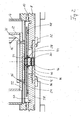
- FIG. 1 shows a sectional view through a mounting device 1 according to a first example for carrying out the present invention. It has a vacuum container 2, comprising a cylindrical housing 4, an upper flange 6 and a lower flange 8. Between adjacent components of the vacuum container 2 a sealing ring 10 is arranged, that can be made of fluoroelastomers, such as those available on the market known as "Viton". These sealing rings 10 ensure the vacuum container 2 is sealed and they are there to absorb shocks and vibrations.
- the cooling unit 12 that is designed as a container for liquid nitrogen as shown in the execution example.
- This container has an inlet 14 and an outlet 16, the inlet 14 being able to let liquid nitrogen into the cooling unit 12, the outlet 16 being able to let gaseous nitrogen out of the cooling unit 12.
- Inlet 14 and outlet 16 are used to form a seal in the upper flange 6 of the vacuum container 2.
- the sealing rings 10 made of a vibration-absorbent material prevent or seriously reduce this being transferred to the lower flange 8 of the vacuum container 2.
- the lower flange 8 has three feet 18, with which the mounting device 1 is arranged on moveable bearings 20. Two of these three feet 18 are shown in figure 1 . They are horizontally moveable in figure 1 , so that the position of the mounting device 1 can be set to a further component of an examination device that is not shown.
- Figure 2 shows an enlarged view of the lower part of figure 1 . You can see the housing 4, a sealing ring 10 and the lower flange 8 of the vacuum container 2. Inside the vacuum container 2 the cooling unit 12 is shown with the lower end of the inlet 14.
- a heat distributor 24 that can, for example, be designed to be made of copper sheets preferably made of oxygen-free copper sheets.
- the heat distributor 24 is arranged with screws 26 on the base element 22 of the cooling unit 12. Between the heat distributor 24 and the base element 22 an indium lining can be used to improve the thermal contact between the two components.
- the lower flange 8 has an opening in the central part, which is closed with a locking element 28.
- This locking element 28 has a window 30 in the central part that can, for example, be made of quartz crystal and is between 0.2 mm and 0.6 mm, preferably 0.5 mm thick.
- the locking element 28 is held by clamps 32 in the opening in the lower flange 8 and can be removed by loosening the clamps 32, giving access to the vacuum container 2 and therefore also the sample.
- contact elements 38 are between the intermediate plate 36 and the lower flange 8 of the vacuum container 2. They are preferably made of teflon and have a very low thermal conductivity reducing a thermal transport from the lower flange 8, which is at room temperature, to the inside of the vacuum container 2.
- a sample mount 40 Arranged on the intermediate plate 36 is a sample mount 40, which does not have direct contact to the intermediate plate 36. On the contrary, a further contact element 42 is arranged between the intermediate plate 36 and the sample mount 40, that is made of polyimide as shown in the execution example. Even this material has a very low thermal conductivity, reducing a heat transfer from the lower flange 8 via the intermediate plate 36 to the sample mount 40.
- the sample mount 40 is connected to the heat distributor 24 via thermal conduction elements 44.
- These thermal conduction elements 44 are preferably made of oxygen-free copper and therefore guarantee a good thermal connection of the sample mount 40 to the heat distributor 24 and therefore also to the base element 22 of the cooling unit 12.
- a sample holder 46 is arranged on the side facing the window 30 of the sample mount 40, on which the actual sample if situated on the side facing the window 30.
- an inlet pipe not shown in the figures, directs for example gaseous nitrogen branched off from a reservoir of liquid nitrogen, into the gap between the vacuum container 2 and the cooling unit 12.
- the locking element 28 can be removed by loosening the clamps 32.
- the cold dry gas that was directed into the vacuum container 2 now exists though the opening in the lower flange 8 and creates a gas stream or gas curtain there, within which the sample with the sample holder 46 can be easily removed from the sample mount 40.
- a new sample can be inserted and the vacuum container 2 closed again.
- the vacuum can be re-established through the inlet pipe or through a separate pipe.
- a mounting device 1 it is possible to cool a sample using liquid nitrogen in the cooling unit 12 to a temperature of about 90 K. This only takes a few minutes. It is also possible, to remove the sample and insert a new one without increasing temperature above 115 K using the displayed and described method without having to heat the interior of the vacuum container. Attempts have shown that, with a mounting device according to the invention, single-molecule microscopy and wide-field microscopy can be carried out, the localization precision being comparable to the molecular size. Further optimizations, for example, by using liquid helium, which would make the method and examination more costly, are not necessary, as achieving a more exact lateral resolution of a corresponding molecular size would not provide any significant additional information.
Landscapes
- Physics & Mathematics (AREA)
- Chemical & Material Sciences (AREA)
- Analytical Chemistry (AREA)
- General Physics & Mathematics (AREA)
- Optics & Photonics (AREA)
- Health & Medical Sciences (AREA)
- Life Sciences & Earth Sciences (AREA)
- Biochemistry (AREA)
- General Health & Medical Sciences (AREA)
- Immunology (AREA)
- Pathology (AREA)
- Sampling And Sample Adjustment (AREA)
Abstract
• a vacuum container (2),
• a cooling unit (12),
• a sample mount (40), which is thermally connected to and can be cooled by the cooling unit (12), and a sample holder (46), that is detachable from the sample mount (40), the sample holder (46), the sample mount (40) and the cooling unit (12) being arranged in the vacuum container (2) and the sample holder (46) being detachable from the sample mount (40), when the sample mount (40) is cooled by the cooling unit (12), without heating a sample, which is in the sample holder (46), to more than the glass transition temperature of water.
Description
- The invention refers to a mounting device for a sample that is to be preferably visually examined. The invention also refers to a visual examination device with a mounting device of this sort and a method for removing a cooled sample from such a mounting device.
- For a multitude of various, particularly visual examination methods, for example visual fluorescence microscopy, it is advantageous, to cool the sample to very low temperatures. This enables, for example, single-molecule fluorescence microscopy to be carried out. For this, so-called cryo microscopes are used to hold the samples to be examined in a mounting device, enabling the sample to be cooled to the desired temperatures. Here, for example, liquid nitrogen or liquid helium is used. Such mounting devices are however also used in other methods and the devices needed to carry out the experiments.
- The corresponding mounting devices for the samples therefore have a cooling device, in which, for example, liquid helium or liquid nitrogen is used. This is kept in a closed container or the liquid coolant is run through the cooling device. Both lead to mechanical fluctuations, vibrations and movements of the cooling device, which should not reach the sample to be examined to ensure a good resolution and examination precision. At the same time however, good thermal contact between the sample and the cooling device must be achieved. Prior art shows a number of different systems that can solve this task.
-
US 8,746,008 B1 describes a system by which the sample or a sample mount, on which the sample is arranged, is connected to the cooling device via flexible copper wires or thin copper sheets. A good heat coupling is achieved due to the high thermal conductivity of the copper and a mechanical decoupling is achieved due to the flexibility of the wires used. In order to achieve a further mechanical decoupling between the cooling device, for which a compressor is used, and the holder for the sample, the two components are not exactly aligned but are aligned offset to one another. This means that the distance for the transport of heat between the sample to be cooled and the cooling device is quite long, leading to quite a slow cooling of the sample. - In order to prevent further thermal radiation and thermal conduction within the device, the sample is arranged in a vacuum chamber, which has to be flushed to exchange the sample. In addition, the device and, particularly the sample, have to be warmed up, to prevent the sample icing over when penetrating air mixes with the moisture inside. This makes changing the sample difficult and time consuming.
- Similar devices are known from
US 4,745,761 andUS 4,161,747 .US 4,161,747 however, refers to a holder for a diode laser, so exchanging a sample, that would correspond to exchanging the diode, is not intended. -
DE 10 2012 019 688 A1 also refers to a similar sample mounting device. - The present invention aims to propose further developing a mounting device according to the preamble so that sufficient thermal and mechanical stability is provided and, at the same time, the sample to be examined can be easily removed or exchanged, without having to expose the sample to heat.
- The invention solves the problem at hand with a mounting device for a sample, that should preferably be visually examined, the mounting device having a vacuum container, a cooling unit, a sample mount, which is thermally connected to and can be cooled by the cooling unit, and a sample holder that is detachable from the sample mount, the sample holder, the sample mount and the cooling unit being arranged in the vacuum container and the sample holder being detachable from the sample mount, when the sample mount is cooled by the cooling unit, without a heating of a sample, which is in the sample holder, to more than the glass transition temperature of water.
- The glass transition temperature of water is the temperature at which the transition between amorphous ice and crystalline ice takes place. When a biological sample is cooled then the water inside the biological cell freezes. If the water forms crystalline ice this will destroy the cell and thus the biological sample. It is however possible to cool biological samples below the glass transition temperature of water so that amorphous ice is formed without the intermediate step of forming crystalline ice. In this case the biological cell stays intact and can be examined. With a mounting device according to the present invention it becomes possible to detach the sample mount and the sample from the remaining parts of the mounting device without heating the sample above this glass transition temperature of water. It thus becomes possible to exchange the sample by another sample without having to use complex and expensive methods of heating and cooling the sample without generating crystalline ice.
- The mounting device therefore has a cooling unit with which the sample mount can be cooled. This is thermally connected to the cooling unit. The sample holder, onto which the actual sample, for example, in the form of a slide, can be arranged, can be arranged on the sample mount itself. This way, sample holder makes thermal contact with the sample mount, so the sample that is preferably to be visually examined, can be cooled. Depending on the used cooling unit and possibly the coolant to be used, the temperature of the sample can be cooled to different target temperatures, for example less than 100 K, less than 90 K or, for example, when using liquid hydrogen, to about 10 K. Preferably the sample is cooled to 89 K using liquid nitrogen or to about 30 K using liquid helium.
- Sample holder, sample mount and cooling unit are arranged in the vacuum container that is evacuated for measuring. A vacuum is hereby produced in the gap between the cooling unit and the vacuum container, so that thermal conduction is either weak or cannot take place. The wall of the vacuum container can, for example, be in contact with the ambient air and therefore have room temperature. In order to avoid a strong build-up of heat in the cooling unit due to thermal radiation of the outer wall of the vacuum container at room temperature, a radiation shield, for example, a polished stainless steel plate can be arranged inside the vacuum container, to serve as a reflector for the thermal radiation emitted by the walls of the vacuum container. It is particularly preferred that this radiation shield surrounds not only the cooling unit but also the sample mount and the sample holder, which may be on it. It is particularly even more preferred to use a window which has a coating, which absorbs infrared radiation, in order to further reduce sample heating.
- A mounting device according to the invention is also designed so that a cooled sample, that is in the sample holder, can be removed from the mounting device. Here, the sample holder is removed from the sample mount and the link between the two elements disconnected. It is important to ensure that the sample is not heated to more than the glass transition temperature of water. Of course, it is also possible to insert another cooled sample holder or the same sample holder with a new sample into the mounting device. For this, the sample holder is arranged on the sample mount while the sample mount is being cooled by the cooling unit. Using the mounting device according to the invention, it is thus possible, to examine various samples using the desired examination method in a relatively short time without heating the sample, the sample holder and the sample mount before the samples in the mounting device can be removed and without cooling the said components when a new sample and/or a new sample holder is inserted, as is necessary when using devices from prior art. For this, a new sample and said components simply have to be cooled by the cooling unit, as long as it has not already been cooled to the desired temperature by another cooling device.
- The invention also solves the problem at hand with a method for removing a cooled sample from a mounting device (1) that has an evacuated vacuum container (2), in which the sample is fixed, the method having the following steps:
- a) Flushing the evacuated vacuum container (2) with a dry gas, which has a temperature of below the glass transition temperature of water,
- b) Opening a suitable opening of the vacuum container (2) to remove the sample, so that the dry gas leaves the vacuum container (2) in a gas stream through the opening,
- c) Loosening the mounting of the sample in the vacuum container (2) and
- d) Removing the sample from the vacuum container (2) within the gas stream.
- This method can be carried out with mounting devices according to the invention and with other mounting devices, in which the sample is kept and cooled in an evacuated vacuum container. It is just important that the vacuum container has an opening through which the sample can be removed or inserted into the vacuum container.
- When changing the sample with a mounting device from prior art, in which the sample is placed in the vacuum container, the vacuum container must be aired first. Pressure balance takes place between the interior and exterior of the vacuum container, during which air flows into the evacuated vacuum container. If, in this condition, for example, liquid helium or liquid nitrogen is in one of the cooling units of the mounting device, the sample is further cooled via the sample mount and a sample holder if present. It is advantageous if the temperature is below the glass transition temperature of water, for example below 115 K. The inflowing air contains a certain amount of moisture that turns to ice and crystallizes out. This leads to an icing over of the interior of the vacuum container and therefore also the sample mount and the sample. Hence the need to initially heat the sample when using prior art devices.
- Using the method according to the present invention, this is no longer necessary. First, the evacuated vacuum container is flushed with a dry gas that has a temperature which is below the glass transition temperature of water. This dry gas can be, for example, liquid nitrogen or helium, this dry gas is preferably taken directly out of a volume in which the liquefied gas is found. This volume can be the volume from which the cooling unit is filled with liquid or liquefied gas. This evaporates and thereby provides the necessary cold dry gas in the desired purity. This guarantees that the dry gas has no moisture, meaning the interior of the vacuum container cannot ice over. After the vacuum container is flushed with the dry gas, the opening of the vacuum container can be opened, enabling access to the sample. Preferably, there will be a constant flow of dry cold gas into the vacuum container, so that it can then leave the vacuum container through the open opening. A gas stream is produced, also referred to as a gas curtain. The temperature inside this gas stream is so low that the cooled sample can be removed. It is important to ensure the sample does not leave the gas stream on removal. As an alternative or in addition to this, the gas stream can also be led into a container that is subsequently largely, nearly completely, or ideally completely filled with the dry cold gas. In this way, an exchange of samples can take place inside the container and the new sample can be inserted through the gas stream into the inside of the open vacuum container. Finally, the vacuum container is closed again and evacuated. No heating of the sample mount or the interior of the vacuum container or a final cooling is needed, meaning an exchange of samples can take place quickly, efficiently and therefore also cheaply.
- In a prefered embodiment of the method according to the present invention the amount of dry gas leaving the vacuum container is increased before loosening the mounting of the sample. After the opening of the vacuum container has been opened in step (b) of the method according to the present invention it is possible to increase the amount of dry gas. Under certain circumstances this is not possible before the opening has been opened since the closed opening might not withstand the pressure of the incoming dry gas.
- A preferred arrangement of a mounting device of the present invention is that the sample mount is fixed on an intermediate plate, which is arranged on an interior of the vacuum container. This is particularly advantageous when the cooling unit is made of a dewar vessel or another container, in which a liquefied gas such as helium or nitrogen can be found. A complete thermal decoupling of the cooling device is obviously not possible, leading to the liquefied gas in the interior of the container boiling and regaining a gas state. This can lead to movements and vibrations, that should, when possible, not reach the sample holder that is on the sample mount. This guarantees the mechanical stability and robustness of the sample to be examined. For this reason, it makes sense to fix the sample mount on the vacuum container via the intermediate plate, but not on the cooling unit. The cooling unit is only in thermal contact with the sample mount, in order to cool the sample in the sample holder. The intermediate plate can, for example, be design as a stainless steel plate.
- It has been proven to be advantageous to arrange the intermediate plate over the contact elements on the interior of the vacuum container, that are made of a material with a lower thermal conductivity than the material of the intermediate plate and the material of the vacuum container. There is therefore advantageously no direct thermal contact between the intermediate plate and the vacuum container, so that no direct heat flux or heat transfer is possible between these two components, whose materials can have a fairly high thermal conductivity. Instead, between these two components, there is at least one contact element with a much lower thermal conductivity. In order to further decrease the thermal flow it is advantageous to choose the contact areas of the contact elements as small as possible.
- Preferably, the sample mount is arranged on the intermediate plate over the contact elements that are made of a material with a lower thermal conductivity than the material of the intermediate plate and the material of the sample mount. This also prevents direct contact and a direct heat transfer between the components.
- Preferably, the contact elements are made of polyimide or teflon. They can be used as spacer elements between the components to be connected, that are subsequently connected using screws that are preferably made of polyimide or teflon. This drastically reduces the warming of the sample via the transfer of heat from the vacuum container to the sample.
- It has been proven to be advantageous to have the cooling unit with a container for storing the liquefied gas, particularly liquid nitrogen or liquid helium. In this way, the desired temperatures can be reached and particularly the use of liquid nitrogen presents a cheap form of cooling unit.
- Preferably, the sample mount is connected to the cooling unit via at least one, but preferably four flexible thermal conduction elements, which are particularly made of copper, but preferably made of oxygen-free copper. Copper is highly conductive and the use of oxygen-free copper makes sure that no oxygen can escape the copper that could reduce the vacuum inside the vacuum container. In addition the risk of corrosion is reduced. As described above, thermal contact between the cooling unit and the sample mount is guaranteed due to the flexibility of the thermal conduction elements but a mechanical decoupling of the two components also occurs. Preferably, a thermal conduction element is made of a number of copper wires, that are twisted together to make them more manageable.
- It has been proven to be particularly advantageous to have at least one heat distributor arranged on the cooling unit, with which the sample mount is thermally connected. It is advantageous if this is made of a copper sheet, preferably made of oxygen-free copper, a thermal energy guiding bed should be arranged between the sheet and the cooling device, which should be made of or contain indium.
- All of these measures are there to guarantee the best possible thermal contact between the cooling unit and the components between the cooling unit and the sample. This ensures a very good thermal contact leading to a high thermal current where it is needed.
- In a particularly preferred arrangement of the mounting device, the sample holder is magnetically coupled to the sample mount. This makes it particularly easy to remove the sample holder from the sample mount and guarantees an easy method to produce a connection between the sample holder and the sample mount. In this way, no screws need to be loosened or tightened.
- It is advantageous for the vacuum container to have at least one window, through which the electromagnetic radiation can be sent to one of the samples arranged in the sample holder. The window is advantageously made of a quartz crystal and is between 0.2 mm and 0.6 mm preferably 0.5 mm thick. This reduces visual distractions and other disruptive effects and guarantees that the window does not lose its form when the vacuum container is evacuated and the vacuum in created in the inside. In addition it becomes possible to use a dry objective having better optical characteristics than immersion objectives. With these values it is possible to adjust the distance between the sample and the objective to be between 1.4 mm and 1.6 mm, preferably 1.5 mm.
- The invention also solves the problem at hand with a visual examination device, particularly a microscope or spectroscope, with a mounting device according to one of the above claims. The microscope can advantageously be a fluorescence microscope. In a preferred arrangement, the window and the opening are positions such in the vacuum container that the electromagnetic radiation from below can penetrate into the mounting device und the vacuum container. In order to extract or remove a sample, it is advantageous to remove the mounting device from the rest of the examination device and, for example, to set it aside, in order to achieve better access to the opening which is otherwise difficult to reach. After exchanging or inserting the sample, the mounting device has to be positioned back to its original direction and position, relative to the rest of the examination device. This happens quite easily using at least three positioning elements, each with a longitudinal groove and a ball element. Here, for example, a part of the mounting element that comprises the ball is arranged on the vacuum container or another component of the mounting device. The corresponding part with the longitudinal groove is positioned, for example, on a sheet or another component of the examination device. The groove can also be designed as rails, for example made of two parallel, bar-shaped objects. If then the mounting device is arranged back on the rest of the examination device, a stable and secure positioning is reached due to the particularly simple arrangement of the mounting elements and it guarantees that the mounting device centralizes itself. It has been proven to be advantageous to use particularly exactly three of such mounting elements, the used longitudinal grooves or rails being arranged offset, each at 120°:
- An example for carrying out the present invention is shown in the drawing and is described in detail as follows. It shows:
-
Figure 1 - a sectional view through the mounting device according to a first example for carrying out the present invention and -
Figure 2 - an enlarged view fromfigure 1 . -
Figure 1 shows a sectional view through a mounting device 1 according to a first example for carrying out the present invention. It has avacuum container 2, comprising a cylindrical housing 4, an upper flange 6 and alower flange 8. Between adjacent components of the vacuum container 2 a sealingring 10 is arranged, that can be made of fluoroelastomers, such as those available on the market known as "Viton". These sealing rings 10 ensure thevacuum container 2 is sealed and they are there to absorb shocks and vibrations. - Within the
vacuum container 2 there is the coolingunit 12, that is designed as a container for liquid nitrogen as shown in the execution example. This container has aninlet 14 and an outlet 16, theinlet 14 being able to let liquid nitrogen into the coolingunit 12, the outlet 16 being able to let gaseous nitrogen out of the coolingunit 12.Inlet 14 and outlet 16 are used to form a seal in the upper flange 6 of thevacuum container 2. Inside the coolingunit 12, the boiling and vaporizing of the nitrogen can lead to vibrations that can be transferred via theinlet 14 and the outlet 16 to the upper flange 6. The sealing rings 10 made of a vibration-absorbent material prevent or seriously reduce this being transferred to thelower flange 8 of thevacuum container 2. - The
lower flange 8 has threefeet 18, with which the mounting device 1 is arranged onmoveable bearings 20. Two of these threefeet 18 are shown infigure 1 . They are horizontally moveable infigure 1 , so that the position of the mounting device 1 can be set to a further component of an examination device that is not shown. -
Figure 2 shows an enlarged view of the lower part offigure 1 . You can see the housing 4, a sealingring 10 and thelower flange 8 of thevacuum container 2. Inside thevacuum container 2 thecooling unit 12 is shown with the lower end of theinlet 14. - At a
base element 22 of the coolingunit 12 there is aheat distributor 24, that can, for example, be designed to be made of copper sheets preferably made of oxygen-free copper sheets. Theheat distributor 24 is arranged withscrews 26 on thebase element 22 of the coolingunit 12. Between theheat distributor 24 and thebase element 22 an indium lining can be used to improve the thermal contact between the two components. - The
lower flange 8 has an opening in the central part, which is closed with a lockingelement 28. This lockingelement 28 has awindow 30 in the central part that can, for example, be made of quartz crystal and is between 0.2 mm and 0.6 mm, preferably 0.5 mm thick. The lockingelement 28 is held by clamps 32 in the opening in thelower flange 8 and can be removed by loosening the clamps 32, giving access to thevacuum container 2 and therefore also the sample. - In the interior 34 of the
vacuum container 2 there is anintermediate plate 36, which does not have direct contact to thelower flange 8. On the contrary,contact elements 38 are between theintermediate plate 36 and thelower flange 8 of thevacuum container 2. They are preferably made of teflon and have a very low thermal conductivity reducing a thermal transport from thelower flange 8, which is at room temperature, to the inside of thevacuum container 2. - Arranged on the
intermediate plate 36 is asample mount 40, which does not have direct contact to theintermediate plate 36. On the contrary, afurther contact element 42 is arranged between theintermediate plate 36 and thesample mount 40, that is made of polyimide as shown in the execution example. Even this material has a very low thermal conductivity, reducing a heat transfer from thelower flange 8 via theintermediate plate 36 to thesample mount 40. - The
sample mount 40 is connected to theheat distributor 24 viathermal conduction elements 44. Thesethermal conduction elements 44 are preferably made of oxygen-free copper and therefore guarantee a good thermal connection of thesample mount 40 to theheat distributor 24 and therefore also to thebase element 22 of the coolingunit 12. - A
sample holder 46 is arranged on the side facing thewindow 30 of thesample mount 40, on which the actual sample if situated on the side facing thewindow 30. - If, when using a mounting device 1 according to
figures 1 and2 , a sample that is in thesample holder 46 needs to be changed, then thevacuum container 2 has to be flushed first. Here, an inlet pipe not shown in the figures, directs for example gaseous nitrogen branched off from a reservoir of liquid nitrogen, into the gap between thevacuum container 2 and thecooling unit 12. As soon as the pressure in the interior of thevacuum container 2 is as big as or bigger than the surrounding external pressure, the lockingelement 28 can be removed by loosening the clamps 32. The cold dry gas that was directed into thevacuum container 2 now exists though the opening in thelower flange 8 and creates a gas stream or gas curtain there, within which the sample with thesample holder 46 can be easily removed from thesample mount 40. By reversing the steps of the method, a new sample can be inserted and thevacuum container 2 closed again. In addition the vacuum can be re-established through the inlet pipe or through a separate pipe. - Using a mounting device 1 according to the invention, it is possible to cool a sample using liquid nitrogen in the
cooling unit 12 to a temperature of about 90 K. This only takes a few minutes. It is also possible, to remove the sample and insert a new one without increasing temperature above 115 K using the displayed and described method without having to heat the interior of the vacuum container. Attempts have shown that, with a mounting device according to the invention, single-molecule microscopy and wide-field microscopy can be carried out, the localization precision being comparable to the molecular size. Further optimizations, for example, by using liquid helium, which would make the method and examination more costly, are not necessary, as achieving a more exact lateral resolution of a corresponding molecular size would not provide any significant additional information. -
- 1 -
- Mounting device
- 2 -
- Vacuum container
- 4 -
- Housing
- 6 -
- Upper flange
- 8 -
- Lower flange
- 10 -
- Sealing ring
- 12 -
- Cooling unit
- 14 -
- Inlet
- 16 -
- Outlet
- 18 -
- Foot
- 20 -
- Bearing
- 22 -
- Base element
- 24 -
- Heat distributor
- 26 -
- Screw
- 28 -
- Locking element
- 30 -
- Window
- 32 -
- Clamp
- 34 -
- Interior
- 36 -
- Intermediate plate
- 38 -
- Contact element
- 40 -
- Sample mount
- 42 -
- Contact element
- 44 -
- Thermal conduction element
- 46 -
- Sample holder
Claims (15)
- A mounting device (1) for a sample, that is to be preferably visually examined, the mounting device (1) having• a vacuum container (2),• a cooling unit (12),• a sample mount (40), which is thermally connected to and can be cooled by the cooling unit (12), and• a sample holder (46), that is detachable from the sample mount (40), the sample holder (46), the sample mount (40) and the cooling unit (12) being arranged in the vacuum container (2) and the sample holder (46) being detachable from the sample mount (40), when the sample mount (40) is cooled by the cooling unit (12), without heating a sample, which is in the sample holder (46), to more than the glass transition temperature of water.
- The mounting device (1) according to claim 1, characterized by the fact that the sample mount (40) is fixed to an intermediate plate (36), which is arranged in the interior (34) of the vacuum container (2).
- The mounting device (1) according to claim 2, characterized by the fact that the intermediate plate (36) is arranged via contact elements (38) in the interior (34) of the vacuum container (2), the contact elements having a lower thermal conductivity than the material of the intermediate plate (36) and the material of the vacuum container (2).
- The mounting device (1) according to claim 2 or 3, characterized by the fact that the sample mount (40) is arranged on the intermediate plate (36) via contact elements (42), that have a lower thermal conductivity than the material of the intermediate plate (36) and the material of the sample mounts (40).
- The mounting device (1) according to claim 3 or 4, characterized by the fact that the contact elements (38, 42) are made of polyimide or teflon.
- The mounting device (1) according to one of the above claims, characterized by the fact that the cooling unit (12) has a container for liquid nitrogen or liquid helium.
- The mounting device (1) according to one of the above claims, characterized by the fact that the sample mount (40) is connected to the cooling unit (12) via at least one, but preferably four flexible thermal conduction elements (44), which are particularly made of copper, but preferably made of oxygen-free copper.
- The mounting device (1) according to one of the above claims characterized by the fact that at least one heat distributor (24) is arranged on the cooling unit (12), the sample mount (40) being thermally connected to the heat distributor (24).
- The mounting device (1) according to claim 8, characterized by the fact that the at least one heat distributor (24) is a sheet made of copper, preferably made of oxygen-free copper, a thermal energy guiding bed, preferably containing indium, being arranged between the sheet and the cooling unit (12).
- The mounting device (1) according to one of the above claims, characterized by the fact that the sample holder (46) is magnetically coupled to the sample mount (40).
- The mounting device (1) according to one of the above claims, characterized by the fact that the vacuum container (2) has at least one window (30), through which electromagnetic radiation can be sent to a sample arranged on the sample holder (46).
- The mounting device (1) according to claim 11, characterized by the fact that the window (30) is made of quartz crystal and is between 0.2 mm and 0.6 mm preferably 0.5 mm thick.
- A visual examination device, particularly a microscope or spectroscope, with a mounting device (1) according to one of the above claims.
- A method for removing a cooled sample from a mounting device (1) that has an evacuated vacuum container (2), in which the sample is fixed, the method having the following steps:a) flushing the evacuated vacuum container (2) with a dry gas, which has a temperature of below the glass transition temperature of water,b) Opening a suitable opening of the vacuum container (2) to remove the sample, so that the dry gas leaves the vacuum container (2) in a gas stream through the opening,c) Loosening the mounting of the sample in the vacuum container (2) andd) Removing the sample from the vacuum container (2) within the gas stream.
- The method according to claim 14, characterized by the fact that before loosening the mounting of the sample the amount of dry gas leaving the vacuum container (2) is increased.
Priority Applications (2)
| Application Number | Priority Date | Filing Date | Title |
|---|---|---|---|
| EP15000318.4A EP3054338A1 (en) | 2015-02-04 | 2015-02-04 | Mounting device for a sample and method for removing a sample |
| US15/008,851 US20160223803A1 (en) | 2015-02-04 | 2016-01-28 | Mounting device for a sample and method for removing a sample |
Applications Claiming Priority (1)
| Application Number | Priority Date | Filing Date | Title |
|---|---|---|---|
| EP15000318.4A EP3054338A1 (en) | 2015-02-04 | 2015-02-04 | Mounting device for a sample and method for removing a sample |
Publications (1)
| Publication Number | Publication Date |
|---|---|
| EP3054338A1 true EP3054338A1 (en) | 2016-08-10 |
Family
ID=52633033
Family Applications (1)
| Application Number | Title | Priority Date | Filing Date |
|---|---|---|---|
| EP15000318.4A Withdrawn EP3054338A1 (en) | 2015-02-04 | 2015-02-04 | Mounting device for a sample and method for removing a sample |
Country Status (2)
| Country | Link |
|---|---|
| US (1) | US20160223803A1 (en) |
| EP (1) | EP3054338A1 (en) |
Families Citing this family (4)
| Publication number | Priority date | Publication date | Assignee | Title |
|---|---|---|---|---|
| CN110794566B (en) * | 2018-08-01 | 2021-09-07 | 深圳华大生命科学研究院 | Positioning device, optical imaging system and assembling method thereof |
| CN109916827B (en) * | 2019-03-08 | 2023-05-26 | 金华职业技术学院 | Electrochemical infrared reflectance spectrum measurement method for sample prepared in vacuum |
| CN112748073B (en) * | 2019-10-31 | 2024-05-31 | 中国石油化工股份有限公司 | Material in-situ characterization sample cell and use method thereof |
| US11996264B1 (en) * | 2023-09-06 | 2024-05-28 | Honeywell Federal Manufacturing & Technologies, Llc | Sample mount for electron backscatter diffraction |
Citations (6)
| Publication number | Priority date | Publication date | Assignee | Title |
|---|---|---|---|---|
| US3701580A (en) * | 1970-12-24 | 1972-10-31 | Nippon Kogaku Kk | Device for quenching and cooling a specimen in a high-temperature microscopic viewing system |
| US4161747A (en) | 1978-02-24 | 1979-07-17 | Nasa | Shock isolator for operating a diode laser on a closed-cycle refrigerator |
| US4745761A (en) | 1985-10-30 | 1988-05-24 | Research & Manufacturing Co., Inc. | Vibration damped cryogenic apparatus |
| JP2013025163A (en) * | 2011-07-22 | 2013-02-04 | Ltlab Inc | Cryostat apparatus for microscope |
| DE102012019688A1 (en) | 2012-10-01 | 2014-04-03 | Dietrich Roscher | Arrangement and method for damping vibrations during microscopic examinations |
| US8746008B1 (en) | 2009-03-29 | 2014-06-10 | Montana Instruments Corporation | Low vibration cryocooled system for low temperature microscopy and spectroscopy applications |
Family Cites Families (4)
| Publication number | Priority date | Publication date | Assignee | Title |
|---|---|---|---|---|
| US5598888A (en) * | 1994-09-23 | 1997-02-04 | Grumman Aerospace Corporation | Cryogenic temperature gradient microscopy chamber |
| US8363404B2 (en) * | 2010-12-14 | 2013-01-29 | International Business Machines Corporation | Implementing loading and heat removal for hub module assembly |
| US8994511B2 (en) * | 2011-09-12 | 2015-03-31 | The Boeing Company | Electronic identification package |
| DE102013105320A1 (en) * | 2013-05-23 | 2014-11-27 | Ev Group E. Thallner Gmbh | Apparatus and method for coating a substrate |
-
2015
- 2015-02-04 EP EP15000318.4A patent/EP3054338A1/en not_active Withdrawn
-
2016
- 2016-01-28 US US15/008,851 patent/US20160223803A1/en not_active Abandoned
Patent Citations (6)
| Publication number | Priority date | Publication date | Assignee | Title |
|---|---|---|---|---|
| US3701580A (en) * | 1970-12-24 | 1972-10-31 | Nippon Kogaku Kk | Device for quenching and cooling a specimen in a high-temperature microscopic viewing system |
| US4161747A (en) | 1978-02-24 | 1979-07-17 | Nasa | Shock isolator for operating a diode laser on a closed-cycle refrigerator |
| US4745761A (en) | 1985-10-30 | 1988-05-24 | Research & Manufacturing Co., Inc. | Vibration damped cryogenic apparatus |
| US8746008B1 (en) | 2009-03-29 | 2014-06-10 | Montana Instruments Corporation | Low vibration cryocooled system for low temperature microscopy and spectroscopy applications |
| JP2013025163A (en) * | 2011-07-22 | 2013-02-04 | Ltlab Inc | Cryostat apparatus for microscope |
| DE102012019688A1 (en) | 2012-10-01 | 2014-04-03 | Dietrich Roscher | Arrangement and method for damping vibrations during microscopic examinations |
Also Published As
| Publication number | Publication date |
|---|---|
| US20160223803A1 (en) | 2016-08-04 |
Similar Documents
| Publication | Publication Date | Title |
|---|---|---|
| US10678039B2 (en) | Cooling systems and methods for cryo super-resolution fluorescence light microscopy and other applications | |
| EP3054338A1 (en) | Mounting device for a sample and method for removing a sample | |
| CA2917035C (en) | Device for cooling a consumer with a super-cooled liquid in a cooling circuit | |
| JP4854396B2 (en) | Cryostat structure with low-temperature refrigerator | |
| US20090293504A1 (en) | Refrigeration installation having a warm and a cold connection element and having a heat pipe which is connected to the connection elements | |
| JP7205944B2 (en) | Cryogenic ultra-high vacuum suitcase | |
| JP4431793B2 (en) | Cryostat | |
| HRP20110205A2 (en) | Cryostat with pulse tube refrigerator and two-stage thermalisation of sample rod | |
| FI2409096T4 (en) | Cryogen free cooling apparatus and method | |
| US20170284725A1 (en) | Cryostat with a first and a second helium tank, which are separated from one another in a liquid-tight manner at least in a lower part | |
| US10222312B2 (en) | Cryogenic temperature controller for volumetric sorption analyzers | |
| CN104380426A (en) | Cryogenic specimen holder and cooling source container | |
| JP6335123B2 (en) | Insulating device and method of operating the insulating device | |
| JP7291730B2 (en) | ROTATING STAGE, ELECTRON MICROSCOPE WITH SUCH STAGE, AND METHOD OF COOLING ROTOR OF SUCH STAGE | |
| CN105474348A (en) | Anti-contamination trap, and vacuum application device | |
| EP2166295A2 (en) | Cryogenic cooling apparatus and method using a sleeve with heat transfer member | |
| JP4759551B2 (en) | Flow cooling magnet system | |
| JP2010133811A (en) | Heat insulated type calorimeter | |
| JP6764902B2 (en) | Sample holder | |
| SU1702127A1 (en) | Cryostat | |
| JP2000208083A (en) | Sample cooling device for electron microscope | |
| US7043968B1 (en) | Directly refrigerated block | |
| US11747076B2 (en) | Remote cooling of super-conducting magnet using closed cycle auxiliary flow circuit in a cryogenic cooling system | |
| CN113418760B (en) | Cleavage device, cleavage apparatus, and cleavage method | |
| Herbert et al. | An efficient continuous flow helium cooling unit for mossbauer experiments |
Legal Events
| Date | Code | Title | Description |
|---|---|---|---|
| PUAI | Public reference made under article 153(3) epc to a published international application that has entered the european phase |
Free format text: ORIGINAL CODE: 0009012 |
|
| AK | Designated contracting states |
Kind code of ref document: A1 Designated state(s): AL AT BE BG CH CY CZ DE DK EE ES FI FR GB GR HR HU IE IS IT LI LT LU LV MC MK MT NL NO PL PT RO RS SE SI SK SM TR |
|
| AX | Request for extension of the european patent |
Extension state: BA ME |
|
| STAA | Information on the status of an ep patent application or granted ep patent |
Free format text: STATUS: REQUEST FOR EXAMINATION WAS MADE |
|
| 17P | Request for examination filed |
Effective date: 20170208 |
|
| RBV | Designated contracting states (corrected) |
Designated state(s): AL AT BE BG CH CY CZ DE DK EE ES FI FR GB GR HR HU IE IS IT LI LT LU LV MC MK MT NL NO PL PT RO RS SE SI SK SM TR |
|
| STAA | Information on the status of an ep patent application or granted ep patent |
Free format text: STATUS: THE APPLICATION IS DEEMED TO BE WITHDRAWN |
|
| 18D | Application deemed to be withdrawn |
Effective date: 20200901 |