EP3054191B1 - Geschlitzte spiralförmige kabelhalterung für hebeanordnung und montageverfahren - Google Patents
Geschlitzte spiralförmige kabelhalterung für hebeanordnung und montageverfahren Download PDFInfo
- Publication number
- EP3054191B1 EP3054191B1 EP16154224.6A EP16154224A EP3054191B1 EP 3054191 B1 EP3054191 B1 EP 3054191B1 EP 16154224 A EP16154224 A EP 16154224A EP 3054191 B1 EP3054191 B1 EP 3054191B1
- Authority
- EP
- European Patent Office
- Prior art keywords
- cable
- retainer
- lifting assembly
- ring
- end fitting
- Prior art date
- Legal status (The legal status is an assumption and is not a legal conclusion. Google has not performed a legal analysis and makes no representation as to the accuracy of the status listed.)
- Active
Links
Images



Classifications
-
- F—MECHANICAL ENGINEERING; LIGHTING; HEATING; WEAPONS; BLASTING
- F16—ENGINEERING ELEMENTS AND UNITS; GENERAL MEASURES FOR PRODUCING AND MAINTAINING EFFECTIVE FUNCTIONING OF MACHINES OR INSTALLATIONS; THERMAL INSULATION IN GENERAL
- F16G—BELTS, CABLES, OR ROPES, PREDOMINANTLY USED FOR DRIVING PURPOSES; CHAINS; FITTINGS PREDOMINANTLY USED THEREFOR
- F16G11/00—Means for fastening cables or ropes to one another or to other objects; Caps or sleeves for fixing on cables or ropes
- F16G11/02—Means for fastening cables or ropes to one another or to other objects; Caps or sleeves for fixing on cables or ropes with parts deformable to grip the cable or cables; Fastening means which engage a sleeve or the like fixed on the cable
- F16G11/025—Fastening means which engage a sleeve or the like fixed on the cable, e.g. caps
-
- F—MECHANICAL ENGINEERING; LIGHTING; HEATING; WEAPONS; BLASTING
- F16—ENGINEERING ELEMENTS AND UNITS; GENERAL MEASURES FOR PRODUCING AND MAINTAINING EFFECTIVE FUNCTIONING OF MACHINES OR INSTALLATIONS; THERMAL INSULATION IN GENERAL
- F16G—BELTS, CABLES, OR ROPES, PREDOMINANTLY USED FOR DRIVING PURPOSES; CHAINS; FITTINGS PREDOMINANTLY USED THEREFOR
- F16G11/00—Means for fastening cables or ropes to one another or to other objects; Caps or sleeves for fixing on cables or ropes
- F16G11/10—Quick-acting fastenings; Clamps holding in one direction only
- F16G11/105—Clamps holding in one direction only
- F16G11/108—Clamps holding in one direction only using a ball or a cylinder
Definitions
- the embodiments herein relate to lifting assemblies and, more particularly, to a helical slotted cable retainer for such lifting assemblies, as well as a method of assembling a lifting assembly.
- Many lifting devices require attachment of a wire rope, such as a cable. This may be done by inserting a cable end fitting into a cable retainer, with the components being relatively dimensioned to prevent inadvertent removal of the cable end fitting during regular use.
- the loading on the lifting device is such that off-center forces may exist, thus requiring the cable end fitting to be a ball type fitting (i.e., spherical).
- the cable is required to be replaced on a regular basis, so attachment of the cable to the lifting device needs to support easy removal and replacement.
- the cable is relatively long (e.g., greater than 200 feet), so it is not practical to thread the entire length of the cable through the lifting device in order to achieve attachment.
- the cable needs to remain securely attached to the lifting device whether there are tension forces or forces in the opposite direction (i.e., compression).
- attachment of the cable is achieved through a retainer ring and a pair of split retainers all located in a cylindrical cavity.
- the split retainers are assembled to the cable end fitting and the retainer ring is positioned on the split retainers. This assembly is then inserted into the cavity of a housing.
- a human installation operator may find difficulty with assembly of the several components described above, particularly due to the split retainer arrangement that must sandwich the cable end fitting.
- the split retainers are pulled against the retainer ring and thus remain attached to the cable end fitting.
- a retaining device is added to prevent detachment of the cable from the lifting device during compressive forces of the cable since such forces may separate the split retainers that otherwise retain the cable end fitting.
- the retaining device is prone to incorrect installation due to the cumbersome assembly effort described above.
- EP 2525117A2 describes an exercise apparatus with a cable replacement assembly.
- US 2014/135181 A2 describes cable end assemblies for exercise machine, as well as exercise machines including such cable end assemblies, and related methods.
- US 2011/240403A1 describes a lifeline connector for use with a self-retracting lifeline with a disconnectable lifeline.
- a lifting according to claim is provided.
- a method of assembling a lifting assembly according to claim 9 is provided.
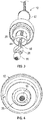
- FIG. 1 a portion of a lifting assembly is illustrated and generally referenced with numeral 10.
- lifting assemblies Several types of lifting assemblies, systems or devices may benefit from the embodiments described herein.
- a crane, hoist or winch are exemplary embodiments of lifting assemblies that would particularly benefit from the embodiments of the invention described herein.
- the preceding list of examples is merely illustrative and it is to be understood that alternative lifting assemblies may incorporate the embodiments of the invention described herein.
- the lifting assembly 10 comprises a cable end housing 12 that defines an inner cavity 14 for housing components for retaining a cable end fitting 16, as will be appreciated from the description herein.
- the cable end housing 12 may be formed of several components that are operatively coupled to each other to form the overall housing ( FIG. 5 ). Additionally, certain components of the cable end housing 12 may be biased in desired manners with various biasing members, such as the springs illustrated in FIG. 5 .
- the inner cavity 14 defined by the cable end housing 12 at an interior region thereof. Although several alternative geometries of the inner cavity 14 are contemplated, an exemplary embodiment of the inner cavity 14 comprises a substantially cylindrical geometry.
- a cable 18 is shown to be disposed within the inner cavity 14 of the cable end housing 12.
- the cable end fitting 16 is disposed and retained within the cable end housing 12 to secure the cable to the portion of the lifting assembly 10.
- the cable end fitting 16 is typically formed of a substantially spherical geometry. Therefore, the cable end fitting 16 may be referred to as a ball type fitting. This geometry accommodates off-center forces that the cable 18 may exert on the lifting assembly 10 due to varied loading angles of loads applied to the cable 18.
- a retainer ring 20 defines an aperture 22 that is sized to fit over the cable end fitting 16 and is inserted into the inner cavity 14 of the cable end housing 12.
- the retainer ring 20 is inserted in a longitudinal direction of the cable end housing 12 to an end 24 of the inner cavity 14, as shown in FIG. 5 .
- the cable retainer 26 includes a first end 28 and a second end 30.
- a curvilinear wall 32 forms the cable retainer 26 and includes a retainer inner surface 34 and a retainer outer surface 36, with the retainer inner surface 34 defining an interior region 37 of the cable retainer 26.
- the cable retainer 26 also defines a slot 38 extending completely through the curvilinear wall 32 and completely from the first end 28 to the second end 30. More specifically, the slot 38 is defined by a first retainer wall 40 and a second retainer wall 42.
- the first and second retainer walls 40, 42 are non-linear along at least a portion of their respective lengths, thereby forming a helical slot along at least a portion of its length. According to the invention, the first and second retainer walls 40, 42 are non-linear along an entirety of their respective lengths, thereby forming a helical slot along an entirety of the slot 38.
- the cable retainer 26 is a single, integrally formed component in contrast to cable retainers having multi-piece designs, such as split collar designs, for example.
- the unitary cable retainer 26 allows an installation operator to easily grip the cable retainer 26 with one hand while inserting the cable 18 through the helical slot 38 by bending the cable to align with the helical orientation of the slot 38.
- the unitary cable retainer 26 may even facilitate one-handed installation of the cable 18 through the slot.
- the cable retainer Upon insertion through the slot 38, the cable retainer is inserted into the inner cavity 14 of the cable end housing 12. Insertion is made until the retainer outer surface 36 of the cable retainer 26 contacts a ring inner surface 44 of the retainer ring 20.
- the retainer outer surface 36 and the ring inner surface 44 have substantially corresponding geometries, such that the cable retainer 26 seats within a portion of the retainer ring 20 upon full insertion of the cable retainer 26 into the cable end housing 12. Typically, the cable retainer 26 and the retainer ring 20 are in direct contact. The cable 18 is then pulled to bring the cable end fitting 16 into contact with the retainer inner surface 34 of the cable retainer 26. Such a final assembled condition is shown in FIGS. 4 and 5 .
- the helical slotted cable retainer 26 described herein has self-retaining capability to the cable end fitting 16, as shown in FIG. 6 . Additionally, installation and removal efforts are substantially simplified in comparison to a cable retainer having multiple components, such as a split collar design. In addition to enhancing the assembly process, a more reliable assembly is achieved with the embodiments of the cable retainer 26 described herein. Specifically, the cable fitting cannot be inadvertently removed from the cable retainer 26, even during a compressive force being applied to the cable 18. This is due to the single component that forms the cable retainer 26. In contrast, a split retainer may loosen during the imposition of a compressive force on the cable 18, thereby extracting the cable 18 and potentially leading to safety hazards.
Landscapes
- Engineering & Computer Science (AREA)
- General Engineering & Computer Science (AREA)
- Mechanical Engineering (AREA)
- Load-Engaging Elements For Cranes (AREA)
Claims (9)
- Hebeanordnung (10), umfassend:ein Kabelende-Gehäuse (12), das einen Innenhohlraum (14) definiert;einen Halterungsring (20), der in dem Innenhohlraum an einem Ende davon angeordnet ist; undein Kabelendfitting (16) und ein Kabel (18);eine Kabelhalterung (26), die in dem Innenhohlraum des Kabelende-Gehäuses angeordnet ist und arbeitet, um das Kabelendfitting (16) des Kabels (18) zu halten, wobei sich die Kabelhalterung von einem ersten Ende (28) zu einem zweiten Ende (30) erstreckt und einen spiralförmigen Schlitz (38) definiert, der sich von dem ersten Ende zu dem zweiten Ende erstreckt, um Installations- und Entfernungszugang des Kabelendfittings bereitzustellen, und dadurch gekennzeichnet, dass die Kabelhalterung (26) eine äußere Halterungsfläche (36) in direktem Kontakt mit einer inneren Ringfläche (44) des Halterungsrings (20) umfasst, undferner wobei der spiralförmige Schlitz (38) von einer ersten Halterungswand (40) und einer zweiten Halterungswand (42) definiert ist,wobei die erste und zweite Halterungswand jeweils entlang einer Gesamtheit davon nicht linear sind.
- Hebeanordnung nach Anspruch 1, wobei die Kabelhalterung (26) eine einzelne, einstückig gebildete Komponente umfasst.
- Hebeanordnung nach Anspruch 1 oder 2, wobei das Kabelendfitting (16) eine sphärische Geometrie umfasst.
- Hebeanordnung nach Anspruch 3, wobei die Kabelhalterung (26) eine innere Halterungsfläche mit einer Geometrie umfasst, die einem Teil der sphärischen Geometrie des Kabelendfittings (16) entspricht.
- Hebeanordnung nach Anspruch 1, wobei die innere Ringfläche eine Geometrie umfasst, die einem Teil der Geometrie der äußeren Halterungsfläche entspricht.
- Hebeanordnung nach einem der vorstehenden Ansprüche, wobei die Hebeanordnung (10) Teil einer Hebevorrichtung ist.
- Hebeanordnung nach einem der Ansprüche 1 bis 5, wobei die Hebeanordnung (10) Teil eines Krans ist.
- Hebeanordnung nach einem der Ansprüche 1 bis 5, wobei die Hebeanordnung (10) Teil einer Winde ist.
- Montageverfahren einer Hebeanordnung nach einem der vorstehenden Ansprüche, umfassend:Anordnen eines Halterungsrings (20) innerhalb eines Innenhohlraums, definiert durch ein Kabelende-Gehäuse (12);Biegen eines Kabels (18), um das Kabel mit einem spiralförmigen Schlitz (38), definiert durch eine Kabelhalterung, auszurichten;Einfügen des Kabels (18) durch den Schlitz (38) in die Kabelhalterung (26);Ziehen des Kabels (18), um ein Kabelendfitting des Kabels in Kontakt mit einer Innenfläche der Kabelhalterung zu bringen; undPlatzieren der Kabelhalterung (26) und des Kabelendfittings innerhalb des Innenhohlraums (14) des Kabelende-Gehäuses und in Kontakt mit dem Halterungsring, und dadurch gekennzeichnet, dass die Kabelhalterung (26) eine äußere Halterungsfläche in direktem Kontakt mit einer inneren Ringfläche des Halterungsrings (20) umfasst, und ferner wobei der spiralförmige Schlitz (38) von einer ersten Halterungswand und einer zweiten Halterungswand definiert ist, wobei die erste und zweite Halterungswand jeweils entlang einer Gesamtheit davon nicht linear sind.
Applications Claiming Priority (1)
| Application Number | Priority Date | Filing Date | Title |
|---|---|---|---|
| US14/614,583 US9506529B2 (en) | 2015-02-05 | 2015-02-05 | Helical slotted cable retainer for lifting assembly and method of assembling |
Publications (2)
| Publication Number | Publication Date |
|---|---|
| EP3054191A1 EP3054191A1 (de) | 2016-08-10 |
| EP3054191B1 true EP3054191B1 (de) | 2018-04-04 |
Family
ID=55299389
Family Applications (1)
| Application Number | Title | Priority Date | Filing Date |
|---|---|---|---|
| EP16154224.6A Active EP3054191B1 (de) | 2015-02-05 | 2016-02-04 | Geschlitzte spiralförmige kabelhalterung für hebeanordnung und montageverfahren |
Country Status (2)
| Country | Link |
|---|---|
| US (1) | US9506529B2 (de) |
| EP (1) | EP3054191B1 (de) |
Families Citing this family (11)
| Publication number | Priority date | Publication date | Assignee | Title |
|---|---|---|---|---|
| CN104884133B (zh) | 2013-03-14 | 2018-02-23 | 艾肯运动与健康公司 | 具有飞轮的力量训练设备 |
| EP3974036B1 (de) | 2013-12-26 | 2024-06-19 | iFIT Inc. | Mechanismus des magnetischen widerstands in einer kabelmaschine |
| WO2015191445A1 (en) | 2014-06-09 | 2015-12-17 | Icon Health & Fitness, Inc. | Cable system incorporated into a treadmill |
| TWI644702B (zh) | 2015-08-26 | 2018-12-21 | 美商愛康運動與健康公司 | 力量運動機械裝置 |
| US10940360B2 (en) | 2015-08-26 | 2021-03-09 | Icon Health & Fitness, Inc. | Strength exercise mechanisms |
| US10293211B2 (en) | 2016-03-18 | 2019-05-21 | Icon Health & Fitness, Inc. | Coordinated weight selection |
| US10441840B2 (en) | 2016-03-18 | 2019-10-15 | Icon Health & Fitness, Inc. | Collapsible strength exercise machine |
| US10252109B2 (en) | 2016-05-13 | 2019-04-09 | Icon Health & Fitness, Inc. | Weight platform treadmill |
| US10661114B2 (en) | 2016-11-01 | 2020-05-26 | Icon Health & Fitness, Inc. | Body weight lift mechanism on treadmill |
| WO2019191658A1 (en) * | 2018-03-29 | 2019-10-03 | Tonal Systems, Inc. | Exercise machine connector |
| CN110901920B (zh) * | 2019-12-04 | 2022-12-06 | 中国直升机设计研究所 | 一种能快速分离的操纵钢索连接装置 |
Family Cites Families (10)
| Publication number | Priority date | Publication date | Assignee | Title |
|---|---|---|---|---|
| US3329455A (en) | 1965-03-29 | 1967-07-04 | Aero Motive Mfg Company | Clamp structure |
| US3332117A (en) | 1965-05-10 | 1967-07-25 | Norco Inc | Releasable cable fastener |
| US20110240403A1 (en) | 2010-03-31 | 2011-10-06 | D B Industries, Inc. | Lifeline Connector for Use with Self-Retracting Lifeline with Disconnectable Lifeline |
| US9065262B2 (en) * | 2010-10-01 | 2015-06-23 | Scott Davidson | Fish tape leader with quick change coupling |
| US8667659B2 (en) * | 2011-01-19 | 2014-03-11 | Mettler-Toledo Ag | System and method for coupling an extendable element to an actuator |
| US8591386B2 (en) | 2011-05-19 | 2013-11-26 | Brunswick Corporation | Exercise apparatus with cable replacement assembly |
| US9537293B2 (en) * | 2012-02-29 | 2017-01-03 | Encore Wire Corporation | Wire pulling head apparatus with crimp zone indicators and method of using same |
| US8839591B2 (en) * | 2012-05-14 | 2014-09-23 | Climb Tech, Llc | Concrete anchor point system |
| US9126071B2 (en) | 2012-10-05 | 2015-09-08 | Icon Health & Fitness, Inc. | Cable end assemblies for exercise machines, exercise machines including such cable end assemblies, and related methods |
| US9254407B2 (en) | 2013-03-13 | 2016-02-09 | Balanced Body, Inc. | Elastic tubing terminator |
-
2015
- 2015-02-05 US US14/614,583 patent/US9506529B2/en active Active
-
2016
- 2016-02-04 EP EP16154224.6A patent/EP3054191B1/de active Active
Non-Patent Citations (1)
| Title |
|---|
| None * |
Also Published As
| Publication number | Publication date |
|---|---|
| US9506529B2 (en) | 2016-11-29 |
| US20160230839A1 (en) | 2016-08-11 |
| EP3054191A1 (de) | 2016-08-10 |
Similar Documents
| Publication | Publication Date | Title |
|---|---|---|
| US9506529B2 (en) | Helical slotted cable retainer for lifting assembly and method of assembling | |
| EP3056761B1 (de) | Geschlitzte kabelhalterung für hebeanordnung und verfahren zur montage | |
| US8591386B2 (en) | Exercise apparatus with cable replacement assembly | |
| CN107781270B (zh) | 带垫圈的螺钉 | |
| DE112012003590T5 (de) | Verbinder | |
| EP2530787A3 (de) | Steckverbinder und Montageverfahren dafür | |
| US10221879B2 (en) | Panel mount fastener having an outer sleeve with a collapsible end portion | |
| WO2014005562A1 (de) | Verriegelungsvorrichtung für einen ladestecker | |
| KR20210030208A (ko) | 볼잠금 연결체 | |
| DE102016123817A1 (de) | Steckverbinder mit einem Druckknopfverriegelungsbügel | |
| EP3369694B1 (de) | Kabelabreisssicherungsvorrichtung | |
| US8430674B2 (en) | Connector with a blade, tool for actuating said connector, kit and fire detector comprising same | |
| CN103449291B (zh) | 乘客传送设备的引导靴拆卸方法和引导靴拆卸工具 | |
| KR101490070B1 (ko) | 케이블 아웃렛 커넥터에 케이블을 고정하기 위한 장치 | |
| WO2005061942A1 (de) | Vorrichtung zum abgedichteten verbinden von zwei endstücken | |
| US8967337B2 (en) | Device for preventing overdrawing of winch hook | |
| EP3269511A1 (de) | Vorrichtung zum greifen von dieselmotorinjektoren | |
| CN109890569A (zh) | 用于取出和插入衬套的装置 | |
| EP4124768A1 (de) | Gewindestangenverbinder mit gewindelosen kontaktflächen | |
| DE112014000590T5 (de) | Optischer Verbinder und Verfahren zum Zusammensetzen von optischem Verbinder | |
| US9197008B1 (en) | Electrical assembly having a threaded coupling nut and retaining ring | |
| JP2009011704A (ja) | ランセット | |
| KR200457490Y1 (ko) | 스프링 삽입부재 및 스프링 삽입부재가 장착된 커넥터 | |
| KR200486952Y1 (ko) | 케이블 벤딩 장치 | |
| US20150028274A1 (en) | Assembly and method for assembling a cable puller |
Legal Events
| Date | Code | Title | Description |
|---|---|---|---|
| PUAI | Public reference made under article 153(3) epc to a published international application that has entered the european phase |
Free format text: ORIGINAL CODE: 0009012 |
|
| AK | Designated contracting states |
Kind code of ref document: A1 Designated state(s): AL AT BE BG CH CY CZ DE DK EE ES FI FR GB GR HR HU IE IS IT LI LT LU LV MC MK MT NL NO PL PT RO RS SE SI SK SM TR |
|
| AX | Request for extension of the european patent |
Extension state: BA ME |
|
| STAA | Information on the status of an ep patent application or granted ep patent |
Free format text: STATUS: REQUEST FOR EXAMINATION WAS MADE |
|
| 17P | Request for examination filed |
Effective date: 20170123 |
|
| RBV | Designated contracting states (corrected) |
Designated state(s): AL AT BE BG CH CY CZ DE DK EE ES FI FR GB GR HR HU IE IS IT LI LT LU LV MC MK MT NL NO PL PT RO RS SE SI SK SM TR |
|
| RIC1 | Information provided on ipc code assigned before grant |
Ipc: F16G 11/02 20060101AFI20170602BHEP |
|
| GRAP | Despatch of communication of intention to grant a patent |
Free format text: ORIGINAL CODE: EPIDOSNIGR1 |
|
| STAA | Information on the status of an ep patent application or granted ep patent |
Free format text: STATUS: GRANT OF PATENT IS INTENDED |
|
| INTG | Intention to grant announced |
Effective date: 20170824 |
|
| GRAS | Grant fee paid |
Free format text: ORIGINAL CODE: EPIDOSNIGR3 |
|
| GRAA | (expected) grant |
Free format text: ORIGINAL CODE: 0009210 |
|
| STAA | Information on the status of an ep patent application or granted ep patent |
Free format text: STATUS: THE PATENT HAS BEEN GRANTED |
|
| AK | Designated contracting states |
Kind code of ref document: B1 Designated state(s): AL AT BE BG CH CY CZ DE DK EE ES FI FR GB GR HR HU IE IS IT LI LT LU LV MC MK MT NL NO PL PT RO RS SE SI SK SM TR |
|
| REG | Reference to a national code |
Ref country code: GB Ref legal event code: FG4D |
|
| REG | Reference to a national code |
Ref country code: CH Ref legal event code: EP |
|
| REG | Reference to a national code |
Ref country code: AT Ref legal event code: REF Ref document number: 985927 Country of ref document: AT Kind code of ref document: T Effective date: 20180415 |
|
| REG | Reference to a national code |
Ref country code: DE Ref legal event code: R096 Ref document number: 602016002258 Country of ref document: DE |
|
| REG | Reference to a national code |
Ref country code: IE Ref legal event code: FG4D |
|
| REG | Reference to a national code |
Ref country code: NL Ref legal event code: MP Effective date: 20180404 |
|
| REG | Reference to a national code |
Ref country code: LT Ref legal event code: MG4D |
|
| PG25 | Lapsed in a contracting state [announced via postgrant information from national office to epo] |
Ref country code: NL Free format text: LAPSE BECAUSE OF FAILURE TO SUBMIT A TRANSLATION OF THE DESCRIPTION OR TO PAY THE FEE WITHIN THE PRESCRIBED TIME-LIMIT Effective date: 20180404 |
|
| PG25 | Lapsed in a contracting state [announced via postgrant information from national office to epo] |
Ref country code: FI Free format text: LAPSE BECAUSE OF FAILURE TO SUBMIT A TRANSLATION OF THE DESCRIPTION OR TO PAY THE FEE WITHIN THE PRESCRIBED TIME-LIMIT Effective date: 20180404 Ref country code: BG Free format text: LAPSE BECAUSE OF FAILURE TO SUBMIT A TRANSLATION OF THE DESCRIPTION OR TO PAY THE FEE WITHIN THE PRESCRIBED TIME-LIMIT Effective date: 20180704 Ref country code: NO Free format text: LAPSE BECAUSE OF FAILURE TO SUBMIT A TRANSLATION OF THE DESCRIPTION OR TO PAY THE FEE WITHIN THE PRESCRIBED TIME-LIMIT Effective date: 20180704 Ref country code: LT Free format text: LAPSE BECAUSE OF FAILURE TO SUBMIT A TRANSLATION OF THE DESCRIPTION OR TO PAY THE FEE WITHIN THE PRESCRIBED TIME-LIMIT Effective date: 20180404 Ref country code: ES Free format text: LAPSE BECAUSE OF FAILURE TO SUBMIT A TRANSLATION OF THE DESCRIPTION OR TO PAY THE FEE WITHIN THE PRESCRIBED TIME-LIMIT Effective date: 20180404 Ref country code: AL Free format text: LAPSE BECAUSE OF FAILURE TO SUBMIT A TRANSLATION OF THE DESCRIPTION OR TO PAY THE FEE WITHIN THE PRESCRIBED TIME-LIMIT Effective date: 20180404 Ref country code: PL Free format text: LAPSE BECAUSE OF FAILURE TO SUBMIT A TRANSLATION OF THE DESCRIPTION OR TO PAY THE FEE WITHIN THE PRESCRIBED TIME-LIMIT Effective date: 20180404 Ref country code: SE Free format text: LAPSE BECAUSE OF FAILURE TO SUBMIT A TRANSLATION OF THE DESCRIPTION OR TO PAY THE FEE WITHIN THE PRESCRIBED TIME-LIMIT Effective date: 20180404 |
|
| PG25 | Lapsed in a contracting state [announced via postgrant information from national office to epo] |
Ref country code: LV Free format text: LAPSE BECAUSE OF FAILURE TO SUBMIT A TRANSLATION OF THE DESCRIPTION OR TO PAY THE FEE WITHIN THE PRESCRIBED TIME-LIMIT Effective date: 20180404 Ref country code: RS Free format text: LAPSE BECAUSE OF FAILURE TO SUBMIT A TRANSLATION OF THE DESCRIPTION OR TO PAY THE FEE WITHIN THE PRESCRIBED TIME-LIMIT Effective date: 20180404 Ref country code: HR Free format text: LAPSE BECAUSE OF FAILURE TO SUBMIT A TRANSLATION OF THE DESCRIPTION OR TO PAY THE FEE WITHIN THE PRESCRIBED TIME-LIMIT Effective date: 20180404 Ref country code: GR Free format text: LAPSE BECAUSE OF FAILURE TO SUBMIT A TRANSLATION OF THE DESCRIPTION OR TO PAY THE FEE WITHIN THE PRESCRIBED TIME-LIMIT Effective date: 20180705 |
|
| REG | Reference to a national code |
Ref country code: AT Ref legal event code: MK05 Ref document number: 985927 Country of ref document: AT Kind code of ref document: T Effective date: 20180404 |
|
| PG25 | Lapsed in a contracting state [announced via postgrant information from national office to epo] |
Ref country code: PT Free format text: LAPSE BECAUSE OF FAILURE TO SUBMIT A TRANSLATION OF THE DESCRIPTION OR TO PAY THE FEE WITHIN THE PRESCRIBED TIME-LIMIT Effective date: 20180806 |
|
| REG | Reference to a national code |
Ref country code: DE Ref legal event code: R097 Ref document number: 602016002258 Country of ref document: DE |
|
| PG25 | Lapsed in a contracting state [announced via postgrant information from national office to epo] |
Ref country code: EE Free format text: LAPSE BECAUSE OF FAILURE TO SUBMIT A TRANSLATION OF THE DESCRIPTION OR TO PAY THE FEE WITHIN THE PRESCRIBED TIME-LIMIT Effective date: 20180404 Ref country code: AT Free format text: LAPSE BECAUSE OF FAILURE TO SUBMIT A TRANSLATION OF THE DESCRIPTION OR TO PAY THE FEE WITHIN THE PRESCRIBED TIME-LIMIT Effective date: 20180404 Ref country code: CZ Free format text: LAPSE BECAUSE OF FAILURE TO SUBMIT A TRANSLATION OF THE DESCRIPTION OR TO PAY THE FEE WITHIN THE PRESCRIBED TIME-LIMIT Effective date: 20180404 Ref country code: RO Free format text: LAPSE BECAUSE OF FAILURE TO SUBMIT A TRANSLATION OF THE DESCRIPTION OR TO PAY THE FEE WITHIN THE PRESCRIBED TIME-LIMIT Effective date: 20180404 Ref country code: SK Free format text: LAPSE BECAUSE OF FAILURE TO SUBMIT A TRANSLATION OF THE DESCRIPTION OR TO PAY THE FEE WITHIN THE PRESCRIBED TIME-LIMIT Effective date: 20180404 Ref country code: DK Free format text: LAPSE BECAUSE OF FAILURE TO SUBMIT A TRANSLATION OF THE DESCRIPTION OR TO PAY THE FEE WITHIN THE PRESCRIBED TIME-LIMIT Effective date: 20180404 |
|
| PLBE | No opposition filed within time limit |
Free format text: ORIGINAL CODE: 0009261 |
|
| STAA | Information on the status of an ep patent application or granted ep patent |
Free format text: STATUS: NO OPPOSITION FILED WITHIN TIME LIMIT |
|
| PG25 | Lapsed in a contracting state [announced via postgrant information from national office to epo] |
Ref country code: SM Free format text: LAPSE BECAUSE OF FAILURE TO SUBMIT A TRANSLATION OF THE DESCRIPTION OR TO PAY THE FEE WITHIN THE PRESCRIBED TIME-LIMIT Effective date: 20180404 Ref country code: IT Free format text: LAPSE BECAUSE OF FAILURE TO SUBMIT A TRANSLATION OF THE DESCRIPTION OR TO PAY THE FEE WITHIN THE PRESCRIBED TIME-LIMIT Effective date: 20180404 |
|
| 26N | No opposition filed |
Effective date: 20190107 |
|
| PG25 | Lapsed in a contracting state [announced via postgrant information from national office to epo] |
Ref country code: SI Free format text: LAPSE BECAUSE OF FAILURE TO SUBMIT A TRANSLATION OF THE DESCRIPTION OR TO PAY THE FEE WITHIN THE PRESCRIBED TIME-LIMIT Effective date: 20180404 |
|
| REG | Reference to a national code |
Ref country code: CH Ref legal event code: PL |
|
| PG25 | Lapsed in a contracting state [announced via postgrant information from national office to epo] |
Ref country code: LU Free format text: LAPSE BECAUSE OF NON-PAYMENT OF DUE FEES Effective date: 20190204 Ref country code: MC Free format text: LAPSE BECAUSE OF FAILURE TO SUBMIT A TRANSLATION OF THE DESCRIPTION OR TO PAY THE FEE WITHIN THE PRESCRIBED TIME-LIMIT Effective date: 20180404 |
|
| REG | Reference to a national code |
Ref country code: BE Ref legal event code: MM Effective date: 20190228 |
|
| REG | Reference to a national code |
Ref country code: IE Ref legal event code: MM4A |
|
| PG25 | Lapsed in a contracting state [announced via postgrant information from national office to epo] |
Ref country code: LI Free format text: LAPSE BECAUSE OF NON-PAYMENT OF DUE FEES Effective date: 20190228 Ref country code: CH Free format text: LAPSE BECAUSE OF NON-PAYMENT OF DUE FEES Effective date: 20190228 |
|
| PG25 | Lapsed in a contracting state [announced via postgrant information from national office to epo] |
Ref country code: IE Free format text: LAPSE BECAUSE OF NON-PAYMENT OF DUE FEES Effective date: 20190204 |
|
| PG25 | Lapsed in a contracting state [announced via postgrant information from national office to epo] |
Ref country code: BE Free format text: LAPSE BECAUSE OF NON-PAYMENT OF DUE FEES Effective date: 20190228 |
|
| PG25 | Lapsed in a contracting state [announced via postgrant information from national office to epo] |
Ref country code: TR Free format text: LAPSE BECAUSE OF FAILURE TO SUBMIT A TRANSLATION OF THE DESCRIPTION OR TO PAY THE FEE WITHIN THE PRESCRIBED TIME-LIMIT Effective date: 20180404 |
|
| PG25 | Lapsed in a contracting state [announced via postgrant information from national office to epo] |
Ref country code: MT Free format text: LAPSE BECAUSE OF NON-PAYMENT OF DUE FEES Effective date: 20190204 |
|
| PG25 | Lapsed in a contracting state [announced via postgrant information from national office to epo] |
Ref country code: CY Free format text: LAPSE BECAUSE OF FAILURE TO SUBMIT A TRANSLATION OF THE DESCRIPTION OR TO PAY THE FEE WITHIN THE PRESCRIBED TIME-LIMIT Effective date: 20180404 |
|
| PG25 | Lapsed in a contracting state [announced via postgrant information from national office to epo] |
Ref country code: IS Free format text: LAPSE BECAUSE OF FAILURE TO SUBMIT A TRANSLATION OF THE DESCRIPTION OR TO PAY THE FEE WITHIN THE PRESCRIBED TIME-LIMIT Effective date: 20180804 |
|
| PG25 | Lapsed in a contracting state [announced via postgrant information from national office to epo] |
Ref country code: HU Free format text: LAPSE BECAUSE OF FAILURE TO SUBMIT A TRANSLATION OF THE DESCRIPTION OR TO PAY THE FEE WITHIN THE PRESCRIBED TIME-LIMIT; INVALID AB INITIO Effective date: 20160204 |
|
| PG25 | Lapsed in a contracting state [announced via postgrant information from national office to epo] |
Ref country code: MK Free format text: LAPSE BECAUSE OF FAILURE TO SUBMIT A TRANSLATION OF THE DESCRIPTION OR TO PAY THE FEE WITHIN THE PRESCRIBED TIME-LIMIT Effective date: 20180404 |
|
| P01 | Opt-out of the competence of the unified patent court (upc) registered |
Effective date: 20230522 |
|
| REG | Reference to a national code |
Ref country code: DE Ref legal event code: R081 Ref document number: 602016002258 Country of ref document: DE Owner name: HORNET ACQUISITIONCO, LLC, VANCOUVER, US Free format text: FORMER OWNER: GOODRICH CORP., CHARLOTTE, N.C., US |
|
| REG | Reference to a national code |
Ref country code: GB Ref legal event code: 732E Free format text: REGISTERED BETWEEN 20250501 AND 20250507 |
|
| PGFP | Annual fee paid to national office [announced via postgrant information from national office to epo] |
Ref country code: GB Payment date: 20260227 Year of fee payment: 11 |
|
| PGFP | Annual fee paid to national office [announced via postgrant information from national office to epo] |
Ref country code: DE Payment date: 20260227 Year of fee payment: 11 |
|
| PGFP | Annual fee paid to national office [announced via postgrant information from national office to epo] |
Ref country code: FR Payment date: 20260225 Year of fee payment: 11 |