EP3054150A1 - Überströmventil für eine hochdruckpumpe sowie hochdruckpumpe - Google Patents
Überströmventil für eine hochdruckpumpe sowie hochdruckpumpe Download PDFInfo
- Publication number
- EP3054150A1 EP3054150A1 EP15200800.9A EP15200800A EP3054150A1 EP 3054150 A1 EP3054150 A1 EP 3054150A1 EP 15200800 A EP15200800 A EP 15200800A EP 3054150 A1 EP3054150 A1 EP 3054150A1
- Authority
- EP
- European Patent Office
- Prior art keywords
- housing
- valve
- overflow valve
- valve body
- inlet opening
- Prior art date
- Legal status (The legal status is an assumption and is not a legal conclusion. Google has not performed a legal analysis and makes no representation as to the accuracy of the status listed.)
- Granted
Links
- 239000000446 fuel Substances 0.000 claims abstract description 12
- 238000002347 injection Methods 0.000 claims abstract description 9
- 239000007924 injection Substances 0.000 claims abstract description 9
- 238000002485 combustion reaction Methods 0.000 claims abstract description 8
- 238000007789 sealing Methods 0.000 claims description 4
- 238000010276 construction Methods 0.000 description 3
- 238000011161 development Methods 0.000 description 3
- 230000018109 developmental process Effects 0.000 description 3
- 238000004519 manufacturing process Methods 0.000 description 3
- 238000012986 modification Methods 0.000 description 2
- 230000004048 modification Effects 0.000 description 2
- 230000010349 pulsation Effects 0.000 description 2
- 238000013459 approach Methods 0.000 description 1
- 239000011324 bead Substances 0.000 description 1
- 238000004891 communication Methods 0.000 description 1
- 230000001419 dependent effect Effects 0.000 description 1
- 238000013461 design Methods 0.000 description 1
- 238000007599 discharging Methods 0.000 description 1
Images


Classifications
-
- F—MECHANICAL ENGINEERING; LIGHTING; HEATING; WEAPONS; BLASTING
- F02—COMBUSTION ENGINES; HOT-GAS OR COMBUSTION-PRODUCT ENGINE PLANTS
- F02M—SUPPLYING COMBUSTION ENGINES IN GENERAL WITH COMBUSTIBLE MIXTURES OR CONSTITUENTS THEREOF
- F02M55/00—Fuel-injection apparatus characterised by their fuel conduits or their venting means; Arrangements of conduits between fuel tank and pump F02M37/00
- F02M55/04—Means for damping vibrations or pressure fluctuations in injection pump inlets or outlets
-
- F—MECHANICAL ENGINEERING; LIGHTING; HEATING; WEAPONS; BLASTING
- F02—COMBUSTION ENGINES; HOT-GAS OR COMBUSTION-PRODUCT ENGINE PLANTS
- F02M—SUPPLYING COMBUSTION ENGINES IN GENERAL WITH COMBUSTIBLE MIXTURES OR CONSTITUENTS THEREOF
- F02M59/00—Pumps specially adapted for fuel-injection and not provided for in groups F02M39/00 -F02M57/00, e.g. rotary cylinder-block type of pumps
- F02M59/44—Details, components parts, or accessories not provided for in, or of interest apart from, the apparatus of groups F02M59/02 - F02M59/42; Pumps having transducers, e.g. to measure displacement of pump rack or piston
- F02M59/46—Valves
- F02M59/462—Delivery valves
-
- F—MECHANICAL ENGINEERING; LIGHTING; HEATING; WEAPONS; BLASTING
- F02—COMBUSTION ENGINES; HOT-GAS OR COMBUSTION-PRODUCT ENGINE PLANTS
- F02M—SUPPLYING COMBUSTION ENGINES IN GENERAL WITH COMBUSTIBLE MIXTURES OR CONSTITUENTS THEREOF
- F02M63/00—Other fuel-injection apparatus having pertinent characteristics not provided for in groups F02M39/00 - F02M57/00 or F02M67/00; Details, component parts, or accessories of fuel-injection apparatus, not provided for in, or of interest apart from, the apparatus of groups F02M39/00 - F02M61/00 or F02M67/00; Combination of fuel pump with other devices, e.g. lubricating oil pump
- F02M63/0012—Valves
- F02M63/0031—Valves characterized by the type of valves, e.g. special valve member details, valve seat details, valve housing details
- F02M63/005—Pressure relief valves
- F02M63/0052—Pressure relief valves with means for adjusting the opening pressure, e.g. electrically controlled
-
- F—MECHANICAL ENGINEERING; LIGHTING; HEATING; WEAPONS; BLASTING
- F02—COMBUSTION ENGINES; HOT-GAS OR COMBUSTION-PRODUCT ENGINE PLANTS
- F02M—SUPPLYING COMBUSTION ENGINES IN GENERAL WITH COMBUSTIBLE MIXTURES OR CONSTITUENTS THEREOF
- F02M63/00—Other fuel-injection apparatus having pertinent characteristics not provided for in groups F02M39/00 - F02M57/00 or F02M67/00; Details, component parts, or accessories of fuel-injection apparatus, not provided for in, or of interest apart from, the apparatus of groups F02M39/00 - F02M61/00 or F02M67/00; Combination of fuel pump with other devices, e.g. lubricating oil pump
- F02M63/0012—Valves
- F02M63/007—Details not provided for in, or of interest apart from, the apparatus of the groups F02M63/0014 - F02M63/0059
- F02M63/0071—Details not provided for in, or of interest apart from, the apparatus of the groups F02M63/0014 - F02M63/0059 characterised by guiding or centering means in valves including the absence of any guiding means, e.g. "flying arrangements"
Definitions
- the invention relates to an overflow valve for a high pressure pump in a fuel injection system of an internal combustion engine with the features of the preamble of claim 1. Furthermore, the invention relates to a high pressure pump with such a spill valve.
- An overflow valve for a high-pressure pump in a fuel injection system is usually used to limit the pressure and / or to reduce pressure pulsations in the region of the inlet of the high-pressure pump.
- the arrangement must therefore be made in such a way that the overflow valve is acted on the input side of the inlet pressure.
- a connection On the output side, a connection must be provided to dissipate the amount of tax deducted.
- an overflow valve for a fuel pump which comprises a housing and a valve body screwed into the housing.
- the overflow valve can be inserted into a pump housing of a fuel pump.
- the housing can also be formed by the pump housing of the fuel pump.
- the arrangement of the overflow valve takes place in such a way that a supply bore of the housing is in communication with an inlet nozzle of the pump.
- the spill valve is connected to a channel in the housing, which opens into a return pipe of the pump.
- connection for overflow valves are known from the prior art.
- a T-shaped adapter piece which is preferably used in a feed line and has a branch from the feed line, the input-side connection of an overflow valve can be realized.
- the present invention seeks to provide an overflow valve for a high pressure pump in a fuel injection system of an internal combustion engine, which simplifies the required connection to an inlet and / or a return of a high-pressure pump. Furthermore, the spill valve should be simple and inexpensive to produce.
- the overflow valve proposed for a high-pressure pump in a fuel injection system of an internal combustion engine comprises a housing and a valve body accommodated at least partially in the housing, the valve body having a central bore in which a valve piston is axially connected to connect an inlet opening formed in the housing to an outlet opening formed in the valve body slidably guided.
- the valve piston is acted upon in the direction of the inlet opening by the spring force of a valve spring.
- the inlet opening and the outlet opening are each formed on the front side in the housing or in the valve body. Accordingly, the overflow valve is not only flowed in axially, but the amount of removal that is to be discharged is also discharged in the axial direction via the end outlet opening in the valve body.
- the inlet port and / or the outlet port is coaxially disposed with respect to a longitudinal axis of the central bore.
- the production of the overflow valve is further simplified.
- the flow through the overflow valve is optimized.
- the flow channel is limited in the direction of the inlet opening by a control edge, which lies in the region of the guidance of the valve piston. Only when the valve piston passes over the control edge, a connection of the inlet opening is made with the outlet opening. On the position of the control edge can therefore be adjusted when the spill valve opens. The movement of the valve piston before the actual opening serves to damp pressure pulsations.
- a plurality of axially extending flow channels are provided for connecting the inlet opening with the outlet opening, which are arranged at the same angular distance from each other.
- the valve piston is thus flowed around evenly when the overflow valve opens.
- the valve body has a hollow-cylindrical projection for forming an outlet channel, which connects the outlet opening with the central bore.
- the overflow valve can be easily connected to a return line via the hollow cylindrical projection, so that the connection to the return is further simplified.
- the hollow cylindrical projection may have an external thread, at least one circumferential bead and / or a groove for non-positive and / or positive connection with a return line. As a result, the seat of the return line is improved on the hollow cylindrical approach.
- the outlet channel has a reduced inner diameter relative to the central bore, so that a shoulder is formed within the central bore for supporting the valve spring.
- the housing has a hollow-cylindrical projection for forming an inlet channel which connects the inlet opening with the central bore.
- the hollow-cylindrical projection forming the inlet channel and thus the inlet opening can be connected in a simple manner with a T-shaped adapter piece, so that the connection to the inlet is simplified by this measure.
- the housing may have an inlet channel designed as a bore, which opens into a feed channel formed in the housing.
- This design of the housing makes a T-shaped adapter unnecessary, so that the construction of the spill valve is further simplified.
- the inlet channel extends transversely to the inlet channel, so that a T-shaped adapter piece is modeled by the housing.
- the inlet channel formed in the housing is formed at least at one end by a side of the housing arranged nozzle.
- the stub facilitates the connection to a supply line, so that ideally both ends of the inlet channel are formed nozzle-shaped.
- the housing and the valve body are non-positively and / or positively connected.
- the valve body is held captive in the housing.
- a certain seal is achieved.
- the non-positive and / or positive connection is realized by a plug-in, screw and / or press connection.
- At least one sealing ring is disposed between the valve body and the housing.
- the overflow valve according to the invention can be an independent component, which is used in the region of the inlet of a high-pressure pump in a supply line.
- the overflow valve according to the invention can also be an integral part of a high-pressure pump.
- Fig. 1 illustrated overflow valve comprises a valve body 2 with a central bore 3, in which a valve piston 6 is guided along a longitudinal axis 8 of the central bore 3 slidably.
- a valve piston 6 In the region of the guide flow channels 9 are formed, which are each bounded by a control edge 11.
- the valve body 2 a total of three flow channels 9, which are each formed as longitudinal grooves and arranged at the same angular distance from each other.
- a valve spring 7 is accommodated, which is supported on the one hand on the valve piston 6 and on the other hand on a shoulder 14 of the valve body 2.
- the valve body 2 is screwed into a housing 1.
- a sealing ring 21 is inserted between the valve body 2 and the housing 1.
- the housing 1 has a hollow cylindrical projection 15, which forms an inlet channel 16 with an inlet opening 4.
- the hollow cylindrical projection 15 can be connected to a T-shaped adapter piece 22, which serves to connect a supply line (not shown). Accordingly, the pressure prevailing in the supply line is also present at the end face of the valve piston 6 facing the inlet channel 16. If this exceeds a predetermined limit value, the valve piston 6 is displaced counter to the spring force of the valve spring 7 in the direction of the shoulder 14. As the control edges 11 pass over, the valve piston 6 releases the flow channels 9, so that a connection of the inlet opening 4 with an outlet opening 5 defines the end of an outlet channel 13 which is formed by a hollow cylindrical projection 12 of the valve body 2.
- the inlet channel 16 with the inlet opening 4 and the outlet channel 13 with the outlet opening 5 are each arranged coaxially to the longitudinal axis 8. In the open position of the overflow valve, this therefore flows through axially.
- the axially extending exhaust passage 13 replaces radially extending Abêtbohrungen, which are usually formed in the valve body 2 for discharging the Ab tenumenge. This eliminates the need to form an annular channel between the valve body 2 and the housing 1, via which the Abschmenge collected can be fed to a return port.
- the hollow-cylindrical projection 12 forming the outlet channel 13 facilitates the connection of a return line (not shown), since it forms a type of connection piece.
- Fig. 3 is a modification of the embodiment of the Fig. 1 shown, which differs in that in the central bore 3, a sleeve 10 is inserted.
- the sleeve 10 serves to guide the valve piston 6. Accordingly, the flow channels 9 are formed in the sleeve 10 (see Fig. 4 ).
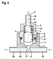
- a further preferred embodiment of the invention shows the Fig. 5 ,
- the housing 1 instead of a hollow-cylindrical projection 15, the housing 1 has a bore for forming an inlet channel 17.
- the inlet channel 17 opens into an inlet channel 18 which extends transversely to the inlet channel 17.
- the inlet channel 18 is formed by nozzles 19, 20, which are attached laterally to the housing 1.
- the T-shaped adapter piece 22 is therefore unnecessary. Incidentally, this corresponds to the Fig. 5 illustrated overflow valve the Fig. 1 ,
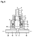
- the Fig. 6 shows a modification of the embodiment of the Fig. 5 in which again a sleeve 10 is used. Otherwise, the overflow valve corresponds to the Fig. 6 the the Fig. 5 ,
Landscapes
- Engineering & Computer Science (AREA)
- Chemical & Material Sciences (AREA)
- Combustion & Propulsion (AREA)
- Mechanical Engineering (AREA)
- General Engineering & Computer Science (AREA)
- Safety Valves (AREA)
- Fuel-Injection Apparatus (AREA)
Abstract
Description
- Die Erfindung betrifft ein Überströmventil für eine Hochdruckpumpe in einem Kraftstoffeinspritzsystem einer Brennkraftmaschine mit den Merkmalen des Oberbegriffs des Anspruchs 1. Ferner betrifft die Erfindung eine Hochdruckpumpe mit einem solchen Überströmventil.
- Ein Überströmventil für eine Hochdruckpumpe in einem Kraftstoffeinspritzsystem wird in der Regel zur Druckbegrenzung und/oder zur Verringerung von Druckpulsationen im Bereich des Zulaufs der Hochdruckpumpe eingesetzt. Die Anordnung hat daher in der Weise zu erfolgen, dass das Überströmventil eingangsseitig vom Zulaufdruck beaufschlagt ist. Ausgangsseitig muss ein Anschluss zum Abführen der anfallenden Absteuermenge vorgesehen werden.
- Aus der Offenlegungsschrift
DE 10 2013 200 050 A1 ist ein Überströmventil für eine Kraftstoffpumpe bekannt, das ein Gehäuse und einen in das Gehäuse eingeschraubten Ventilkörper umfasst. Mit dem Gehäuse kann das Überströmventil in ein Pumpengehäuse einer Kraftstoffpumpe eingesetzt werden. Alternativ kann das Gehäuse aber auch durch das Pumpengehäuse der Kraftstoffpumpe ausgebildet werden. Die Anordnung des Überströmventils erfolgt in der Weise, dass eine Versorgungsbohrung des Gehäuses in Verbindung mit einem Zulaufstutzen der Pumpe steht. Über eine Absteuerbohrung des Überströmventils, welche als Radialbohrung im Ventilkörper ausgebildet ist, ist das Überströmventil mit einem Kanal im Gehäuse verbunden, der in einen Rücklaufstutzen der Pumpe mündet. - Darüber hinaus sind aus dem Stand der Technik weitere Anschlussarten für Überströmventile bekannt. Beispielsweise kann unter Zuhilfenahme eines T-förmigen Adapterstücks, das vorzugsweise in eine Zulaufleitung eingesetzt wird und einen Abzweig von der Zulaufleitung besitzt, der eingangseitige Anschluss eines Überströmventils realisiert werden.
- Ausgehend von dem vorstehend genannten Stand der Technik liegt der vorliegenden Erfindung die Aufgabe zugrunde, ein Überströmventil für eine Hochdruckpumpe in einem Kraftstoffeinspritzsystem einer Brennkraftmaschine anzugeben, das den erforderlichen Anschluss an einen Zulauf und/oder einen Rücklauf einer Hochdruckpumpe vereinfacht. Ferner soll das Überströmventil einfach und kostengünstig herstellbar sein.
- Zur Lösung der Aufgabe wird das Überströmventil mit den Merkmalen des Anspruchs 1 angegeben. Vorteilhafte Weiterbildungen der Erfindung sind den Unteransprüchen zu entnehmen. Ferner wird eine Hochdruckpumpe mit einem solchen Überströmventil vorgeschlagen.
- Das für eine Hochdruckpumpe in einem Kraftstoffeinspritzsystem einer Brennkraftmaschine vorgeschlagene Überströmventil umfasst ein Gehäuse und einen zumindest bereichsweise in dem Gehäuse aufgenommenen Ventilkörper, wobei der Ventilkörper eine zentrale Bohrung besitzt, in der zur Verbindung einer im Gehäuse ausgebildeten Einlassöffnung mit einer im Ventilkörper ausgebildeten Auslassöffnung ein Ventilkolben axial verschiebbar geführt ist. Der Ventilkolben ist dabei in Richtung der Einlassöffnung von der Federkraft einer Ventilfeder beaufschlagt. Erfindungsgemäß sind die Einlassöffnung und die Auslassöffnung jeweils stirnseitig im Gehäuse bzw. im Ventilkörper ausgebildet. Das Überströmventil wird demnach nicht nur axial angeströmt, sondern die abzuführende Absteuermenge wird auch in axialer Richtung über die stirnseitige Auslassöffnung im Ventilkörper abgeführt. Das heißt, dass radial verlaufende Absteuerbohrungen entfallen können. Aufgrund dessen kann ferner auf einen ringförmigen Kanal zwischen dem Gehäuse und dem Ventilkörper verzichtet werden, der üblicherweise dem Anschluss des Überströmventils an einen Rücklauf dient. Denn bei dem erfindungsgemäßen Überströmventil kann die stirnseitig im Ventilkörper vorgesehene Auslassöffnung direkt an den Rücklauf angeschlossen werden. Dies erleichtert nicht nur die Herstellung des ausgangsseitigen Anschlusses des Überströmventils, sondern vereinfacht zugleich dessen Aufbau. Der eingangsseitige Anschluss kann über ein herkömmliches T-förmiges Adapterstück oder - wenn das Überströmventil in die Hochdruckpumpe integriert ist - über einen Abzweig eines Zulaufkanals realisiert werden. Im letztgenannten Fall kann das Gehäuse des Überströmventils auch durch ein Gehäuseteil der Hochdruckpumpe ausgebildet werden.
- Bevorzugt ist bzw. sind die Einlassöffnung und/oder die Auslassöffnung koaxial in Bezug auf eine Längsachse der zentralen Bohrung angeordnet. Dadurch wird die Herstellung des Überströmventils weiter vereinfacht. Zugleich wird die Strömung durch das Überströmventil optimiert.
- Des Weiteren bevorzugt ist im Bereich der Führung des Ventilkolbens mindestens ein axial verlaufender Strömungskanal zur Verbindung der Einlassöffnung mit der Auslassöffnung vorgesehen. Eine Verbindung besteht jedoch nur dann, wenn der Zulaufdruck eine Öffnungskraft auf den Ventilkolben ausübt, so dass dieser entgegen der Federkraft der Ventilfeder axial verschoben wird. Der erforderliche Öffnungsdruck ist über die Ventilfeder einstellbar. Vorzugsweise ist der Strömungskanal als Längsnut ausgeführt, die im Ventilkörper oder in einer hierin eingesetzten Hülse zur Führung des Ventilkolbens ausgebildet ist. Ein als Längsnut ausgeführter Strömungskanal ist zudem einfach herstellbar.
- Ferner wird vorgeschlagen, dass der Strömungskanal in Richtung der Einlassöffnung von einer Steuerkante begrenzt wird, die im Bereich der Führung des Ventilkolbens liegt. Erst, wenn der Ventilkolben die Steuerkante überfährt, ist eine Verbindung der Einlassöffnung mit der Auslassöffnung hergestellt. Über die Lage der Steuerkante kann demnach eingestellt werden, wann das Überströmventil öffnet. Die Bewegung des Ventilkolbens vor dem eigentlichen Öffnen dient der Dämpfung von Druckpulsationen.
- Vorteilhafterweise sind mehrere axial verlaufende Strömungskanäle zur Verbindung der Einlassöffnung mit der Auslassöffnung vorgesehen, die in gleichem Winkelabstand zueinander angeordnet sind. Der Ventilkolben wird somit gleichmäßig umströmt, wenn das Überströmventil öffnet.
- In Weiterbildung der Erfindung wird vorgeschlagen, dass der Ventilkörper einen hohlzylinderförmigen Ansatz zur Ausbildung eines Auslasskanals besitzt, der die Auslassöffnung mit der zentralen Bohrung verbindet. Über den hohlzylinderförmigen Ansatz kann das Überströmventil in einfacher Weise mit einer Rücklaufleitung verbunden werden, so dass der Anschluss an den Rücklauf weiter vereinfacht wird. Ferner kann der hohlzylinderförmige Ansatz ein Außengewinde, mindestens einen umlaufenden Wulst und/oder eine Rillung zur kraft- und/oder formschlüssigen Verbindung mit einer Rücklaufleitung aufweisen. Dadurch wird der Sitz der Rücklaufleitung auf dem hohlzylinderförmigen Ansatz verbessert.
- Vorzugsweise besitzt der Auslasskanal gegenüber der zentralen Bohrung einen verringerten Innendurchmesser, so dass ein Absatz innerhalb der zentralen Bohrung zur Abstützung der Ventilfeder ausgebildet wird. Die über den Absatz am Ventilkörper vorgesehene Abstützung macht einen Federhalter entbehrlich, der üblicherweise zur Abstützung der Ventilfeder in die Bohrung des Ventilkörpers eingepresst wird. Der Wegfall des Federhalters vereinfacht den Aufbau des Überströmventils.
- Als weiterbildende Maßnahme wird ferner vorgeschlagen, dass das Gehäuse einen hohlzylinderförmigen Ansatz zur Ausbildung eines Einlasskanals besitzt, der die Einlassöffnung mit der zentralen Bohrung verbindet. Der den Einlasskanal und damit die Einlassöffnung ausbildende hohlzylinderförmige Ansatz kann in einfacher Weise mit einem T-förmigen Adapterstück verbunden werden, so dass durch diese Maßnahme der Anschluss an den Zulauf vereinfacht wird.
- Alternativ kann das Gehäuse einen als Bohrung ausgeführten Einlasskanal besitzen, der in einen im Gehäuse ausgebildeten Zulaufkanal mündet. Diese Ausführung des Gehäuses macht ein T-förmiges Adapterstück entbehrlich, so dass der Aufbau des Überströmventils weiter vereinfacht wird. Vorzugsweise verläuft der Zulaufkanal quer zum Einlasskanal, so dass ein T-förmiges Adapterstück durch das Gehäuse nachgebildet wird.
- Vorzugsweise wird der im Gehäuse ausgebildete Zulaufkanal zumindest an einem Ende durch einen seitlich am Gehäuse angeordneten Stutzen ausgebildet. Der Stutzen erleichtert den Anschluss an eine Zulaufleitung, so dass idealerweise beide Enden des Zulaufkanals stutzenförmig ausgebildet sind.
- Vorteilhafterweise sind das Gehäuse und der Ventilkörper kraft- und/oder formschlüssig verbunden. Durch eine solche Verbindung ist der Ventilkörper verliersicher im Gehäuse gehalten. Ferner wird eine gewisse Abdichtung erreicht. Vorzugsweise ist die kraft- und/oder formschlüssige Verbindung durch eine Steck-, Schraub- und/oder Pressverbindung realisiert.
- Zur Optimierung der Abdichtung wird ferner vorgeschlagen, dass zwischen dem Ventilkörper und dem Gehäuse mindestens ein Dichtring angeordnet ist.
- Wie bereits eingangs erwähnt, kann das erfindungsgemäße Überströmventil ein eigenständiges Bauteil sein, das im Bereich des Zulaufs einer Hochdruckpumpe in eine Zulaufleitung eingesetzt wird. Darüber hinaus kann das erfindungsgemäße Überströmventil jedoch auch integraler Bestandteil einer Hochdruckpumpe sein.
- Daher wird ferner eine Hochdruckpumpe für ein Kraftstoffeinspritzsystem einer Brennkraftmaschine mit einem erfindungsgemäßen Überströmventil vorgeschlagen, bei welcher das Gehäuse des Überströmventils durch ein Gehäuseteil der Hochdruckpumpe gebildet wird.
- Bevorzugte Ausführungsformen der Erfindung werden nachfolgend anhand der beigefügten Zeichnungen näher erläutert. Diese zeigen:
-
Fig. 1 einen schematischen Längsschnitt durch ein erfindungsgemäßes Überströmventil gemäß einer ersten bevorzugten Ausführungsform, -
Fig. 2 einen schematischen Querschnitt durch das Überströmventil derFig. 1 , -
Fig. 3 einen schematischen Längsschnitt durch ein erfindungsgemäßes Überströmventil gemäß einer zweiten bevorzugten Ausführungsform, -
Fig. 4 einen schematischen Querschnitt durch das Überströmventil derFig. 3 , -
Fig. 5 einen schematischen Längsschnitt durch ein erfindungsgemäßes Überströmventil gemäß einer dritten bevorzugten Ausführungsform und -
Fig. 6 einen schematischen Längsschnitt durch ein erfindungsgemäßes Überströmventil gemäß einer vierten bevorzugten Ausführungsform. - Das in der
Fig. 1 dargestellte Überströmventil umfasst einen Ventilkörper 2 mit einer zentralen Bohrung 3, in welcher ein Ventilkolben 6 entlang einer Längsachse 8 der zentralen Bohrung 3 verschiebbar geführt ist. Im Bereich der Führung sind Strömungskanäle 9 ausgebildet, die jeweils von einer Steuerkante 11 begrenzt werden. Wie derFig. 2 zu entnehmen ist, weist der Ventilkörper 2 insgesamt drei Strömungskanäle 9 auf, die jeweils als Längsnuten ausgebildet und in gleichem Winkelabstand zueinander angeordnet sind. In der zentralen Bohrung 3 ist neben dem Ventilkolben 6 eine Ventilfeder 7 aufgenommen, die einerseits am Ventilkolben 6 und andererseits an einem Absatz 14 des Ventilkörpers 2 abgestützt ist. - Der Ventilkörper 2 ist in ein Gehäuse 1 eingeschraubt. Zur Abdichtung ist zwischen dem Ventilkörper 2 und dem Gehäuse 1 ein Dichtring 21 eingelegt. Das Gehäuse 1 weist einen hohlzylinderförmigen Ansatz 15 auf, der einen Einlasskanal 16 mit einer Einlassöffnung 4 ausbildet. Der hohlzylinderförmige Ansatz 15 kann mit einem T-förmigen Adapterstück 22 verbunden werden, das dem Anschluss einer Zulaufleitung (nicht dargestellt) dient. Der in der Zulaufleitung herrschende Druck liegt demnach auch an der dem Einlasskanal 16 zugewandten Stirnseite des Ventilkolbens 6 an. Steigt dieser über einen vorgegebenen Grenzwert, wird der Ventilkolben 6 entgegen der Federkraft der Ventilfeder 7 in Richtung des Absatzes 14 verschoben. Mit Überfahren der Steuerkanten 11 gibt der Ventilkolben 6 die Strömungskanäle 9 frei, so dass eine Verbindung der Einlassöffnung 4 mit einer Auslassöffnung 5 besteht, die das Ende eines Auslasskanals 13 definiert, der durch einen hohlzylinderförmigen Ansatz 12 des Ventilkörpers 2 gebildet wird.
- Der Einlasskanal 16 mit der Einlassöffnung 4 und der Auslasskanal 13 mit der Auslassöffnung 5 sind jeweils koaxial zur Längsachse 8 angeordnet. In Offenstellung des Überströmventils wird dieses demnach axial durchströmt. Der axial verlaufende Auslasskanal 13 ersetzt radial verlaufende Absteuerbohrungen, die üblicherweise im Ventilkörper 2 zum Abführen der Absteuermenge ausgebildet sind. Damit entfällt auch die Notwendigkeit einen Ringkanal zwischen dem Ventilkörper 2 und dem Gehäuse 1 auszubilden, über welchen die Absteuermenge gesammelt einem Rücklaufanschluss zugeführt werden kann. Ferner erleichtert der den Auslasskanal 13 ausbildende hohlzylinderförmige Ansatz 12 den Anschluss einer Rücklaufleitung (nicht dargestellt), da er eine Art Anschlussstutzen ausbildet.
- In der
Fig. 3 ist eine Abwandlung der Ausführungsform derFig. 1 dargestellt, die sich dadurch unterscheidet, dass in die zentrale Bohrung 3 eine Hülse 10 eingesetzt ist. Die Hülse 10 dient der Führung des Ventilkolbens 6. Entsprechend sind die Strömungskanäle 9 in der Hülse 10 ausgebildet (sieheFig. 4 ). - Eine weitere bevorzugte Ausführungsform der Erfindung zeigt die
Fig. 5 . Hier weist das Gehäuse 1 anstelle eines hohlzylinderförmigen Ansatzes 15 eine Bohrung zur Ausbildung eines Einlasskanals 17 auf. Der Einlasskanal 17 mündet in einen Zulaufkanal 18, der quer zum Einlasskanal 17 verläuft. An seinen beiden Enden wird der Zulaufkanal 18 durch Stutzen 19, 20 gebildet, die seitlich an das Gehäuse 1 angesetzt sind. Das T-förmige Adapterstück 22 ist demnach entbehrlich. Im Übrigen entspricht das in derFig. 5 dargestellte Überströmventil dem derFig. 1 . - Die
Fig. 6 zeigt eine Abwandlung der Ausführungsform derFig. 5 , bei der wiederum eine Hülse 10 zum Einsatz gelangt. Im Übrigen entspricht das Überströmventil derFig. 6 dem derFig. 5 . - Die hohlzylinderförmigen Ansätze 12, 15 bzw. die Stutzen 19, 20 ermöglichen in einfacher Weise den Anschluss des erfindungsgemäßen Überströmventils an einen Zulauf bzw. an einen Rücklauf. Ferner weist ein erfindungsgemäßes Überströmventil einen einfachen Aufbau auf und ist somit kostengünstig herstellbar. Wird das Gehäuse 1 von einem Gehäuseteil einer Hochdruckpumpe gebildet, weist das Überströmventil nur wenige Teile auf, so dass die Herstellungskosten weiter gesenkt werden.
Claims (11)
- Überströmventil für eine Hochdruckpumpe in einem Kraftstoffeinspritzsystem einer Brennkraftmaschine, umfassend ein Gehäuse (1) und einen zumindest bereichsweise in dem Gehäuse (1) aufgenommenen Ventilkörper (2), wobei der Ventilkörper (2) eine zentrale Bohrung (3) besitzt, in der zur Verbindung einer im Gehäuse (1) ausgebildeten Einlassöffnung (4) mit einer im Ventilkörper (2) ausgebildeten Auslassöffnung (5) ein Ventilkolben (6) axial verschiebbar geführt ist, und wobei der Ventilkolben (6) in Richtung der Einlassöffnung (4) von der Federkraft einer Ventilfeder (7) beaufschlagt ist,
dadurch gekennzeichnet, dass die Einlassöffnung (4) und die Auslassöffnung (5) jeweils stirnseitig im Gehäuse (1) bzw. im Ventilkörper (2) ausgebildet sind. - Überströmventil nach Anspruch 1,
dadurch gekennzeichnet, dass die Einlassöffnung (4) und/oder die Auslassöffnung (5) koaxial in Bezug auf eine Längsachse (8) der zentralen Bohrung (3) angeordnet ist bzw. sind. - Überströmventil nach Anspruch 1 oder 2,
dadurch gekennzeichnet, dass im Bereich der Führung des Ventilkolbens (6) mindestens ein axial verlaufender Strömungskanal (9) zur Verbindung der Einlassöffnung (4) mit der Auslassöffnung (5) vorgesehen ist, wobei vorzugsweise der Strömungskanal (9) als Längsnut ausgeführt ist, die im Ventilkörper (2) oder in einer hierin eingesetzten Hülse (10) zur Führung des Ventilkolbens (6) ausgebildet ist. - Überströmventil nach Anspruch 3,
dadurch gekennzeichnet, dass der Strömungskanal (9) in Richtung der Einlassöffnung (4) von einer Steuerkante (11) begrenzt wird, die im Bereich der Führung des Ventilkolbens (6) liegt. - Überströmventil nach Anspruch 3 oder 4,
dadurch gekennzeichnet, dass mehrere axial verlaufende Strömungskanäle (9) zur Verbindung der Einlassöffnung (4) mit der Auslassöffnung (5) vorgesehen sind, die in gleichem Winkelabstand zueinander angeordnet sind. - Überströmventil nach einem der vorhergehenden Ansprüche,
dadurch gekennzeichnet, dass der Ventilkörper (2) einen hohlzylinderförmigen Ansatz (12) zur Ausbildung eines Auslasskanals (13) besitzt, der die Auslassöffnung (5) mit der zentralen Bohrung (3) verbindet, wobei vorzugsweise der Auslasskanal (13) gegenüber der zentralen Bohrung (3) einen verringerten Innendurchmesser besitzt, so dass ein Absatz (14) innerhalb der zentralen Bohrung (3) zur Abstützung der Ventilfeder (7) ausgebildet wird. - Überströmventil nach einem der vorhergehenden Ansprüche,
dadurch gekennzeichnet, dass das Gehäuse (1) einen hohlzylinderförmigen Ansatz (15) zur Ausbildung eines Einlasskanals (16) besitzt, der die Einlassöffnung (4) mit der zentralen Bohrung (3) verbindet. - Überströmventil nach einem der Ansprüche 1 bis 6,
dadurch gekennzeichnet, dass das Gehäuse (1) einen als Bohrung ausgeführten Einlasskanal (17) besitzt, der in einen im Gehäuse (1) ausgebildeten Zulaufkanal (18) mündet, wobei vorzugsweise der Zulaufkanal (18) zumindest an einem Ende durch einen seitlich am Gehäuse (1) angeordneten Stutzen (19, 20) ausgebildet wird. - Überströmventil nach einem der vorhergehenden Ansprüche,
dadurch gekennzeichnet, dass das Gehäuse (1) und der Ventilkörper (2) kraft- und/oder formschlüssig verbunden sind, wobei die kraft- und/oder formschlüssige Verbindung vorzugsweise durch eine Steck-, Schraub- und/oder Pressverbindung realisiert ist. - Überströmventil nach einem der vorhergehenden Ansprüche,
dadurch gekennzeichnet, dass zwischen dem Ventilkörper (2) und dem Gehäuse (1) mindestens ein Dichtring (21) angeordnet ist. - Hochdruckpumpe für ein Kraftstoffeinspritzsystem einer Brennkraftmaschine mit einem Überströmventil nach einem der vorhergehenden Ansprüche, wobei das Gehäuse (1) durch ein Gehäuseteil der Hochdruckpumpe gebildet wird.
Applications Claiming Priority (1)
| Application Number | Priority Date | Filing Date | Title |
|---|---|---|---|
| DE102015202022.3A DE102015202022A1 (de) | 2015-02-05 | 2015-02-05 | Überströmventil für eine Hochdruckpumpe sowie Hochdruckpumpe |
Publications (2)
| Publication Number | Publication Date |
|---|---|
| EP3054150A1 true EP3054150A1 (de) | 2016-08-10 |
| EP3054150B1 EP3054150B1 (de) | 2019-02-27 |
Family
ID=54936847
Family Applications (1)
| Application Number | Title | Priority Date | Filing Date |
|---|---|---|---|
| EP15200800.9A Active EP3054150B1 (de) | 2015-02-05 | 2015-12-17 | Überströmventil für eine hochdruckpumpe sowie hochdruckpumpe |
Country Status (2)
| Country | Link |
|---|---|
| EP (1) | EP3054150B1 (de) |
| DE (1) | DE102015202022A1 (de) |
Families Citing this family (1)
| Publication number | Priority date | Publication date | Assignee | Title |
|---|---|---|---|---|
| DE102016218407A1 (de) | 2016-09-26 | 2018-03-29 | Schaeffler Technologies AG & Co. KG | Hydraulisches Schaltelement |
Citations (6)
| Publication number | Priority date | Publication date | Assignee | Title |
|---|---|---|---|---|
| FR797444A (fr) * | 1934-12-05 | 1936-04-27 | Belfrost Diesels Ltd | Perfectionnements apportés aux systèmes d'injection de combustible |
| US2234932A (en) * | 1937-11-20 | 1941-03-11 | Timken Roller Bearing Co | Fuel injection delivery valve |
| US2352322A (en) * | 1942-01-02 | 1944-06-27 | Ex Cell O Corp | Pressure reduction check valve |
| DE2651586B1 (de) * | 1976-11-12 | 1978-04-27 | Maschf Augsburg Nuernberg Ag | Befestigung eines ringfoermigen Widerlagers fuer die Schliessfeder eines Ventils einer Kraftstoffeinspritzpumpe fuer Brennkraftmaschinen |
| DE102012221543A1 (de) * | 2012-11-26 | 2014-05-28 | Robert Bosch Gmbh | Ventileinrichtung |
| DE102013200050A1 (de) | 2013-01-03 | 2014-07-03 | Robert Bosch Gmbh | Überströmventil für eine Kraftstoffpumpe |
Family Cites Families (1)
| Publication number | Priority date | Publication date | Assignee | Title |
|---|---|---|---|---|
| DE19535368C2 (de) * | 1995-09-25 | 1998-04-30 | Bosch Gmbh Robert | Kraftstoffeinspritzeinrichtung für Brennkraftmaschinen |
-
2015
- 2015-02-05 DE DE102015202022.3A patent/DE102015202022A1/de not_active Withdrawn
- 2015-12-17 EP EP15200800.9A patent/EP3054150B1/de active Active
Patent Citations (6)
| Publication number | Priority date | Publication date | Assignee | Title |
|---|---|---|---|---|
| FR797444A (fr) * | 1934-12-05 | 1936-04-27 | Belfrost Diesels Ltd | Perfectionnements apportés aux systèmes d'injection de combustible |
| US2234932A (en) * | 1937-11-20 | 1941-03-11 | Timken Roller Bearing Co | Fuel injection delivery valve |
| US2352322A (en) * | 1942-01-02 | 1944-06-27 | Ex Cell O Corp | Pressure reduction check valve |
| DE2651586B1 (de) * | 1976-11-12 | 1978-04-27 | Maschf Augsburg Nuernberg Ag | Befestigung eines ringfoermigen Widerlagers fuer die Schliessfeder eines Ventils einer Kraftstoffeinspritzpumpe fuer Brennkraftmaschinen |
| DE102012221543A1 (de) * | 2012-11-26 | 2014-05-28 | Robert Bosch Gmbh | Ventileinrichtung |
| DE102013200050A1 (de) | 2013-01-03 | 2014-07-03 | Robert Bosch Gmbh | Überströmventil für eine Kraftstoffpumpe |
Also Published As
| Publication number | Publication date |
|---|---|
| EP3054150B1 (de) | 2019-02-27 |
| DE102015202022A1 (de) | 2016-08-11 |
Similar Documents
| Publication | Publication Date | Title |
|---|---|---|
| DE102016217923B3 (de) | Rückschlagventil, hochdruckführendes Bauteil und Kraftstoffhochdruckpumpe | |
| EP2670969B1 (de) | Kraftstoffeinspritzsystem mit überströmventil | |
| DE102013216889B4 (de) | Überströmventil für ein Kraftstoffeinspritzsystem sowie Kraftstoffeinspritzsystem | |
| DE112019002212T5 (de) | Verbinder | |
| EP3054150B1 (de) | Überströmventil für eine hochdruckpumpe sowie hochdruckpumpe | |
| EP4310304A1 (de) | Verbindungsvorrichtung zur strömungsverbindung zwischen einem kraftstoff-zuleitungssystem und einer düsenvorrichtung, düsenvorrichtung und gasturbinenanordnung | |
| DE10247958A1 (de) | Kraftstoff-Einspritzvorrichtung für eine Brennkraftmaschine | |
| DE102011083475A1 (de) | Hydraulikventil für ein Kraftstoffeinspritzsystem sowie Kraftstoffeinspritzsystem | |
| DE102014214886B4 (de) | Doppeltwirkendes Rückschlagventil | |
| DE19953888B4 (de) | Leckageanschluss mit Rastsicherung | |
| DE112019002078T5 (de) | Verbinder | |
| EP2511514B1 (de) | Brennstoffeinspritzventil | |
| EP1671029B1 (de) | KRAFTSTOFF-EINSPRITZVORRICHTUNG, INSBESONDERE FüR EINE BRENNKRAFTMASCHINE MIT KRAFTSTOFF-DIREKTEINSPRITZUNG | |
| WO2018069020A1 (de) | Überströmventil, insbesondere für eine hochdruckpumpe, sowie hochdruckpumpe und kraftstoffeinspritzsystem | |
| DE102013210957A1 (de) | Steuerbares Saugventil für eine Hochdruckpumpe | |
| EP2905669B1 (de) | Druckregelventil | |
| WO2019238176A1 (de) | Rückschlagventil, hochdruckführendes bauteil und kraftstoffhochdruckpumpe | |
| DE102006050033A1 (de) | Injektor, insbesondere Common-Rail-Injektor | |
| WO2018065235A1 (de) | Drosselelement, insbesondere für eine hochdruckpumpe, insbesondere eines niederdruckkreis eines kraftstoffeinspritzsystems | |
| DE102018203145A1 (de) | Düsenbaugruppe für ein Kraftstoffeinspritzventil zum Einspritzen eines gasförmigen und/oder flüssigen Kraftstoffs, Kraftstoffeinspritzventil | |
| DE102018200359A1 (de) | Ventilanordnung zur Gasdruckregelung, Kraftstoffsystem mit Ventilanordnung zur Gasdruckregelung | |
| DE102018202807A1 (de) | Ventilanordnung zur Gasdruckregelung, Kraftstoffsystem mit Ventilanordnung zur Gasdruckregelung | |
| DE102018201734A1 (de) | Überströmventil für ein Kraftstoffeinspritzsystem, Kraftstoffeinspritzsystem | |
| DE102011089964A1 (de) | Drucksteuerventil für ein Kraftstoffeinspritzsystem sowie Kraftstoffeinspritzsystem | |
| EP2955366B1 (de) | Düsenbaugruppe für einen kraftstoffinjektor sowie kraftstoffinjektor |
Legal Events
| Date | Code | Title | Description |
|---|---|---|---|
| PUAI | Public reference made under article 153(3) epc to a published international application that has entered the european phase |
Free format text: ORIGINAL CODE: 0009012 |
|
| AK | Designated contracting states |
Kind code of ref document: A1 Designated state(s): AL AT BE BG CH CY CZ DE DK EE ES FI FR GB GR HR HU IE IS IT LI LT LU LV MC MK MT NL NO PL PT RO RS SE SI SK SM TR |
|
| AX | Request for extension of the european patent |
Extension state: BA ME |
|
| STAA | Information on the status of an ep patent application or granted ep patent |
Free format text: STATUS: REQUEST FOR EXAMINATION WAS MADE |
|
| 17P | Request for examination filed |
Effective date: 20170210 |
|
| RBV | Designated contracting states (corrected) |
Designated state(s): AL AT BE BG CH CY CZ DE DK EE ES FI FR GB GR HR HU IE IS IT LI LT LU LV MC MK MT NL NO PL PT RO RS SE SI SK SM TR |
|
| STAA | Information on the status of an ep patent application or granted ep patent |
Free format text: STATUS: EXAMINATION IS IN PROGRESS |
|
| 17Q | First examination report despatched |
Effective date: 20170717 |
|
| GRAP | Despatch of communication of intention to grant a patent |
Free format text: ORIGINAL CODE: EPIDOSNIGR1 |
|
| STAA | Information on the status of an ep patent application or granted ep patent |
Free format text: STATUS: GRANT OF PATENT IS INTENDED |
|
| INTG | Intention to grant announced |
Effective date: 20181102 |
|
| GRAS | Grant fee paid |
Free format text: ORIGINAL CODE: EPIDOSNIGR3 |
|
| GRAA | (expected) grant |
Free format text: ORIGINAL CODE: 0009210 |
|
| STAA | Information on the status of an ep patent application or granted ep patent |
Free format text: STATUS: THE PATENT HAS BEEN GRANTED |
|
| AK | Designated contracting states |
Kind code of ref document: B1 Designated state(s): AL AT BE BG CH CY CZ DE DK EE ES FI FR GB GR HR HU IE IS IT LI LT LU LV MC MK MT NL NO PL PT RO RS SE SI SK SM TR |
|
| REG | Reference to a national code |
Ref country code: GB Ref legal event code: FG4D Free format text: NOT ENGLISH |
|
| REG | Reference to a national code |
Ref country code: CH Ref legal event code: EP |
|
| REG | Reference to a national code |
Ref country code: AT Ref legal event code: REF Ref document number: 1101713 Country of ref document: AT Kind code of ref document: T Effective date: 20190315 |
|
| REG | Reference to a national code |
Ref country code: IE Ref legal event code: FG4D Free format text: LANGUAGE OF EP DOCUMENT: GERMAN |
|
| REG | Reference to a national code |
Ref country code: DE Ref legal event code: R096 Ref document number: 502015008110 Country of ref document: DE |
|
| REG | Reference to a national code |
Ref country code: NL Ref legal event code: MP Effective date: 20190227 |
|
| REG | Reference to a national code |
Ref country code: LT Ref legal event code: MG4D |
|
| PG25 | Lapsed in a contracting state [announced via postgrant information from national office to epo] |
Ref country code: PT Free format text: LAPSE BECAUSE OF FAILURE TO SUBMIT A TRANSLATION OF THE DESCRIPTION OR TO PAY THE FEE WITHIN THE PRESCRIBED TIME-LIMIT Effective date: 20190627 Ref country code: SE Free format text: LAPSE BECAUSE OF FAILURE TO SUBMIT A TRANSLATION OF THE DESCRIPTION OR TO PAY THE FEE WITHIN THE PRESCRIBED TIME-LIMIT Effective date: 20190227 Ref country code: LT Free format text: LAPSE BECAUSE OF FAILURE TO SUBMIT A TRANSLATION OF THE DESCRIPTION OR TO PAY THE FEE WITHIN THE PRESCRIBED TIME-LIMIT Effective date: 20190227 Ref country code: NO Free format text: LAPSE BECAUSE OF FAILURE TO SUBMIT A TRANSLATION OF THE DESCRIPTION OR TO PAY THE FEE WITHIN THE PRESCRIBED TIME-LIMIT Effective date: 20190527 Ref country code: FI Free format text: LAPSE BECAUSE OF FAILURE TO SUBMIT A TRANSLATION OF THE DESCRIPTION OR TO PAY THE FEE WITHIN THE PRESCRIBED TIME-LIMIT Effective date: 20190227 |
|
| PG25 | Lapsed in a contracting state [announced via postgrant information from national office to epo] |
Ref country code: BG Free format text: LAPSE BECAUSE OF FAILURE TO SUBMIT A TRANSLATION OF THE DESCRIPTION OR TO PAY THE FEE WITHIN THE PRESCRIBED TIME-LIMIT Effective date: 20190527 Ref country code: IS Free format text: LAPSE BECAUSE OF FAILURE TO SUBMIT A TRANSLATION OF THE DESCRIPTION OR TO PAY THE FEE WITHIN THE PRESCRIBED TIME-LIMIT Effective date: 20190627 Ref country code: RS Free format text: LAPSE BECAUSE OF FAILURE TO SUBMIT A TRANSLATION OF THE DESCRIPTION OR TO PAY THE FEE WITHIN THE PRESCRIBED TIME-LIMIT Effective date: 20190227 Ref country code: LV Free format text: LAPSE BECAUSE OF FAILURE TO SUBMIT A TRANSLATION OF THE DESCRIPTION OR TO PAY THE FEE WITHIN THE PRESCRIBED TIME-LIMIT Effective date: 20190227 Ref country code: NL Free format text: LAPSE BECAUSE OF FAILURE TO SUBMIT A TRANSLATION OF THE DESCRIPTION OR TO PAY THE FEE WITHIN THE PRESCRIBED TIME-LIMIT Effective date: 20190227 Ref country code: GR Free format text: LAPSE BECAUSE OF FAILURE TO SUBMIT A TRANSLATION OF THE DESCRIPTION OR TO PAY THE FEE WITHIN THE PRESCRIBED TIME-LIMIT Effective date: 20190528 Ref country code: HR Free format text: LAPSE BECAUSE OF FAILURE TO SUBMIT A TRANSLATION OF THE DESCRIPTION OR TO PAY THE FEE WITHIN THE PRESCRIBED TIME-LIMIT Effective date: 20190227 |
|
| PG25 | Lapsed in a contracting state [announced via postgrant information from national office to epo] |
Ref country code: RO Free format text: LAPSE BECAUSE OF FAILURE TO SUBMIT A TRANSLATION OF THE DESCRIPTION OR TO PAY THE FEE WITHIN THE PRESCRIBED TIME-LIMIT Effective date: 20190227 Ref country code: IT Free format text: LAPSE BECAUSE OF FAILURE TO SUBMIT A TRANSLATION OF THE DESCRIPTION OR TO PAY THE FEE WITHIN THE PRESCRIBED TIME-LIMIT Effective date: 20190227 Ref country code: SK Free format text: LAPSE BECAUSE OF FAILURE TO SUBMIT A TRANSLATION OF THE DESCRIPTION OR TO PAY THE FEE WITHIN THE PRESCRIBED TIME-LIMIT Effective date: 20190227 Ref country code: AL Free format text: LAPSE BECAUSE OF FAILURE TO SUBMIT A TRANSLATION OF THE DESCRIPTION OR TO PAY THE FEE WITHIN THE PRESCRIBED TIME-LIMIT Effective date: 20190227 Ref country code: DK Free format text: LAPSE BECAUSE OF FAILURE TO SUBMIT A TRANSLATION OF THE DESCRIPTION OR TO PAY THE FEE WITHIN THE PRESCRIBED TIME-LIMIT Effective date: 20190227 Ref country code: EE Free format text: LAPSE BECAUSE OF FAILURE TO SUBMIT A TRANSLATION OF THE DESCRIPTION OR TO PAY THE FEE WITHIN THE PRESCRIBED TIME-LIMIT Effective date: 20190227 Ref country code: ES Free format text: LAPSE BECAUSE OF FAILURE TO SUBMIT A TRANSLATION OF THE DESCRIPTION OR TO PAY THE FEE WITHIN THE PRESCRIBED TIME-LIMIT Effective date: 20190227 Ref country code: CZ Free format text: LAPSE BECAUSE OF FAILURE TO SUBMIT A TRANSLATION OF THE DESCRIPTION OR TO PAY THE FEE WITHIN THE PRESCRIBED TIME-LIMIT Effective date: 20190227 |
|
| REG | Reference to a national code |
Ref country code: DE Ref legal event code: R097 Ref document number: 502015008110 Country of ref document: DE |
|
| PG25 | Lapsed in a contracting state [announced via postgrant information from national office to epo] |
Ref country code: SM Free format text: LAPSE BECAUSE OF FAILURE TO SUBMIT A TRANSLATION OF THE DESCRIPTION OR TO PAY THE FEE WITHIN THE PRESCRIBED TIME-LIMIT Effective date: 20190227 Ref country code: PL Free format text: LAPSE BECAUSE OF FAILURE TO SUBMIT A TRANSLATION OF THE DESCRIPTION OR TO PAY THE FEE WITHIN THE PRESCRIBED TIME-LIMIT Effective date: 20190227 |
|
| PLBE | No opposition filed within time limit |
Free format text: ORIGINAL CODE: 0009261 |
|
| STAA | Information on the status of an ep patent application or granted ep patent |
Free format text: STATUS: NO OPPOSITION FILED WITHIN TIME LIMIT |
|
| 26N | No opposition filed |
Effective date: 20191128 |
|
| PG25 | Lapsed in a contracting state [announced via postgrant information from national office to epo] |
Ref country code: SI Free format text: LAPSE BECAUSE OF FAILURE TO SUBMIT A TRANSLATION OF THE DESCRIPTION OR TO PAY THE FEE WITHIN THE PRESCRIBED TIME-LIMIT Effective date: 20190227 |
|
| PG25 | Lapsed in a contracting state [announced via postgrant information from national office to epo] |
Ref country code: TR Free format text: LAPSE BECAUSE OF FAILURE TO SUBMIT A TRANSLATION OF THE DESCRIPTION OR TO PAY THE FEE WITHIN THE PRESCRIBED TIME-LIMIT Effective date: 20190227 |
|
| REG | Reference to a national code |
Ref country code: CH Ref legal event code: PL |
|
| REG | Reference to a national code |
Ref country code: BE Ref legal event code: MM Effective date: 20191231 |
|
| PG25 | Lapsed in a contracting state [announced via postgrant information from national office to epo] |
Ref country code: MC Free format text: LAPSE BECAUSE OF FAILURE TO SUBMIT A TRANSLATION OF THE DESCRIPTION OR TO PAY THE FEE WITHIN THE PRESCRIBED TIME-LIMIT Effective date: 20190227 |
|
| GBPC | Gb: european patent ceased through non-payment of renewal fee |
Effective date: 20191217 |
|
| PG25 | Lapsed in a contracting state [announced via postgrant information from national office to epo] |
Ref country code: GB Free format text: LAPSE BECAUSE OF NON-PAYMENT OF DUE FEES Effective date: 20191217 Ref country code: IE Free format text: LAPSE BECAUSE OF NON-PAYMENT OF DUE FEES Effective date: 20191217 Ref country code: LU Free format text: LAPSE BECAUSE OF NON-PAYMENT OF DUE FEES Effective date: 20191217 Ref country code: FR Free format text: LAPSE BECAUSE OF NON-PAYMENT OF DUE FEES Effective date: 20191231 |
|
| PG25 | Lapsed in a contracting state [announced via postgrant information from national office to epo] |
Ref country code: BE Free format text: LAPSE BECAUSE OF NON-PAYMENT OF DUE FEES Effective date: 20191231 Ref country code: CH Free format text: LAPSE BECAUSE OF NON-PAYMENT OF DUE FEES Effective date: 20191231 Ref country code: LI Free format text: LAPSE BECAUSE OF NON-PAYMENT OF DUE FEES Effective date: 20191231 |
|
| PG25 | Lapsed in a contracting state [announced via postgrant information from national office to epo] |
Ref country code: CY Free format text: LAPSE BECAUSE OF FAILURE TO SUBMIT A TRANSLATION OF THE DESCRIPTION OR TO PAY THE FEE WITHIN THE PRESCRIBED TIME-LIMIT Effective date: 20190227 |
|
| PG25 | Lapsed in a contracting state [announced via postgrant information from national office to epo] |
Ref country code: HU Free format text: LAPSE BECAUSE OF FAILURE TO SUBMIT A TRANSLATION OF THE DESCRIPTION OR TO PAY THE FEE WITHIN THE PRESCRIBED TIME-LIMIT; INVALID AB INITIO Effective date: 20151217 Ref country code: MT Free format text: LAPSE BECAUSE OF FAILURE TO SUBMIT A TRANSLATION OF THE DESCRIPTION OR TO PAY THE FEE WITHIN THE PRESCRIBED TIME-LIMIT Effective date: 20190227 |
|
| REG | Reference to a national code |
Ref country code: AT Ref legal event code: MM01 Ref document number: 1101713 Country of ref document: AT Kind code of ref document: T Effective date: 20201217 |
|
| PG25 | Lapsed in a contracting state [announced via postgrant information from national office to epo] |
Ref country code: AT Free format text: LAPSE BECAUSE OF NON-PAYMENT OF DUE FEES Effective date: 20201217 |
|
| PG25 | Lapsed in a contracting state [announced via postgrant information from national office to epo] |
Ref country code: MK Free format text: LAPSE BECAUSE OF FAILURE TO SUBMIT A TRANSLATION OF THE DESCRIPTION OR TO PAY THE FEE WITHIN THE PRESCRIBED TIME-LIMIT Effective date: 20190227 |
|
| PGFP | Annual fee paid to national office [announced via postgrant information from national office to epo] |
Ref country code: DE Payment date: 20240227 Year of fee payment: 9 |