EP3054100B1 - Befestigungsanordnung in einer mittelturbinenrahmenanordnung - Google Patents
Befestigungsanordnung in einer mittelturbinenrahmenanordnung Download PDFInfo
- Publication number
- EP3054100B1 EP3054100B1 EP16153908.5A EP16153908A EP3054100B1 EP 3054100 B1 EP3054100 B1 EP 3054100B1 EP 16153908 A EP16153908 A EP 16153908A EP 3054100 B1 EP3054100 B1 EP 3054100B1
- Authority
- EP
- European Patent Office
- Prior art keywords
- bushing
- fastener
- mid
- turbine
- tie rod
- Prior art date
- Legal status (The legal status is an assumption and is not a legal conclusion. Google has not performed a legal analysis and makes no representation as to the accuracy of the status listed.)
- Active
Links
- 238000001816 cooling Methods 0.000 claims description 21
- 230000004323 axial length Effects 0.000 claims description 10
- 238000012546 transfer Methods 0.000 claims description 6
- 239000000463 material Substances 0.000 claims description 5
- 238000009434 installation Methods 0.000 claims description 3
- 238000000034 method Methods 0.000 claims description 3
- 239000000446 fuel Substances 0.000 description 5
- 238000004891 communication Methods 0.000 description 2
- 230000009467 reduction Effects 0.000 description 2
- 230000003068 static effect Effects 0.000 description 2
- 230000008859 change Effects 0.000 description 1
- 238000002485 combustion reaction Methods 0.000 description 1
- 230000006835 compression Effects 0.000 description 1
- 238000007906 compression Methods 0.000 description 1
- 238000012937 correction Methods 0.000 description 1
- 230000001419 dependent effect Effects 0.000 description 1
- 239000012530 fluid Substances 0.000 description 1
- 238000004519 manufacturing process Methods 0.000 description 1
- 230000007246 mechanism Effects 0.000 description 1
- 238000012986 modification Methods 0.000 description 1
- 230000004048 modification Effects 0.000 description 1
- 230000004044 response Effects 0.000 description 1
- 239000007787 solid Substances 0.000 description 1
Images


Classifications
-
- F—MECHANICAL ENGINEERING; LIGHTING; HEATING; WEAPONS; BLASTING
- F01—MACHINES OR ENGINES IN GENERAL; ENGINE PLANTS IN GENERAL; STEAM ENGINES
- F01D—NON-POSITIVE DISPLACEMENT MACHINES OR ENGINES, e.g. STEAM TURBINES
- F01D25/00—Component parts, details, or accessories, not provided for in, or of interest apart from, other groups
- F01D25/28—Supporting or mounting arrangements, e.g. for turbine casing
-
- F—MECHANICAL ENGINEERING; LIGHTING; HEATING; WEAPONS; BLASTING
- F01—MACHINES OR ENGINES IN GENERAL; ENGINE PLANTS IN GENERAL; STEAM ENGINES
- F01D—NON-POSITIVE DISPLACEMENT MACHINES OR ENGINES, e.g. STEAM TURBINES
- F01D9/00—Stators
- F01D9/06—Fluid supply conduits to nozzles or the like
- F01D9/065—Fluid supply or removal conduits traversing the working fluid flow, e.g. for lubrication-, cooling-, or sealing fluids
-
- F—MECHANICAL ENGINEERING; LIGHTING; HEATING; WEAPONS; BLASTING
- F01—MACHINES OR ENGINES IN GENERAL; ENGINE PLANTS IN GENERAL; STEAM ENGINES
- F01D—NON-POSITIVE DISPLACEMENT MACHINES OR ENGINES, e.g. STEAM TURBINES
- F01D25/00—Component parts, details, or accessories, not provided for in, or of interest apart from, other groups
- F01D25/08—Cooling; Heating; Heat-insulation
- F01D25/12—Cooling
-
- F—MECHANICAL ENGINEERING; LIGHTING; HEATING; WEAPONS; BLASTING
- F01—MACHINES OR ENGINES IN GENERAL; ENGINE PLANTS IN GENERAL; STEAM ENGINES
- F01D—NON-POSITIVE DISPLACEMENT MACHINES OR ENGINES, e.g. STEAM TURBINES
- F01D25/00—Component parts, details, or accessories, not provided for in, or of interest apart from, other groups
- F01D25/16—Arrangement of bearings; Supporting or mounting bearings in casings
- F01D25/162—Bearing supports
-
- F—MECHANICAL ENGINEERING; LIGHTING; HEATING; WEAPONS; BLASTING
- F01—MACHINES OR ENGINES IN GENERAL; ENGINE PLANTS IN GENERAL; STEAM ENGINES
- F01D—NON-POSITIVE DISPLACEMENT MACHINES OR ENGINES, e.g. STEAM TURBINES
- F01D25/00—Component parts, details, or accessories, not provided for in, or of interest apart from, other groups
- F01D25/24—Casings; Casing parts, e.g. diaphragms, casing fastenings
- F01D25/26—Double casings; Measures against temperature strain in casings
-
- F—MECHANICAL ENGINEERING; LIGHTING; HEATING; WEAPONS; BLASTING
- F01—MACHINES OR ENGINES IN GENERAL; ENGINE PLANTS IN GENERAL; STEAM ENGINES
- F01D—NON-POSITIVE DISPLACEMENT MACHINES OR ENGINES, e.g. STEAM TURBINES
- F01D5/00—Blades; Blade-carrying members; Heating, heat-insulating, cooling or antivibration means on the blades or the members
- F01D5/02—Blade-carrying members, e.g. rotors
-
- F—MECHANICAL ENGINEERING; LIGHTING; HEATING; WEAPONS; BLASTING
- F02—COMBUSTION ENGINES; HOT-GAS OR COMBUSTION-PRODUCT ENGINE PLANTS
- F02C—GAS-TURBINE PLANTS; AIR INTAKES FOR JET-PROPULSION PLANTS; CONTROLLING FUEL SUPPLY IN AIR-BREATHING JET-PROPULSION PLANTS
- F02C7/00—Features, components parts, details or accessories, not provided for in, or of interest apart form groups F02C1/00 - F02C6/00; Air intakes for jet-propulsion plants
- F02C7/12—Cooling of plants
-
- F—MECHANICAL ENGINEERING; LIGHTING; HEATING; WEAPONS; BLASTING
- F05—INDEXING SCHEMES RELATING TO ENGINES OR PUMPS IN VARIOUS SUBCLASSES OF CLASSES F01-F04
- F05D—INDEXING SCHEME FOR ASPECTS RELATING TO NON-POSITIVE-DISPLACEMENT MACHINES OR ENGINES, GAS-TURBINES OR JET-PROPULSION PLANTS
- F05D2220/00—Application
- F05D2220/30—Application in turbines
- F05D2220/32—Application in turbines in gas turbines
- F05D2220/321—Application in turbines in gas turbines for a special turbine stage
- F05D2220/3213—Application in turbines in gas turbines for a special turbine stage an intermediate stage of the turbine
-
- F—MECHANICAL ENGINEERING; LIGHTING; HEATING; WEAPONS; BLASTING
- F05—INDEXING SCHEMES RELATING TO ENGINES OR PUMPS IN VARIOUS SUBCLASSES OF CLASSES F01-F04
- F05D—INDEXING SCHEME FOR ASPECTS RELATING TO NON-POSITIVE-DISPLACEMENT MACHINES OR ENGINES, GAS-TURBINES OR JET-PROPULSION PLANTS
- F05D2240/00—Components
- F05D2240/20—Rotors
- F05D2240/24—Rotors for turbines
-
- F—MECHANICAL ENGINEERING; LIGHTING; HEATING; WEAPONS; BLASTING
- F05—INDEXING SCHEMES RELATING TO ENGINES OR PUMPS IN VARIOUS SUBCLASSES OF CLASSES F01-F04
- F05D—INDEXING SCHEME FOR ASPECTS RELATING TO NON-POSITIVE-DISPLACEMENT MACHINES OR ENGINES, GAS-TURBINES OR JET-PROPULSION PLANTS
- F05D2260/00—Function
- F05D2260/20—Heat transfer, e.g. cooling
-
- F—MECHANICAL ENGINEERING; LIGHTING; HEATING; WEAPONS; BLASTING
- F05—INDEXING SCHEMES RELATING TO ENGINES OR PUMPS IN VARIOUS SUBCLASSES OF CLASSES F01-F04
- F05D—INDEXING SCHEME FOR ASPECTS RELATING TO NON-POSITIVE-DISPLACEMENT MACHINES OR ENGINES, GAS-TURBINES OR JET-PROPULSION PLANTS
- F05D2260/00—Function
- F05D2260/30—Retaining components in desired mutual position
- F05D2260/31—Retaining bolts or nuts
-
- Y—GENERAL TAGGING OF NEW TECHNOLOGICAL DEVELOPMENTS; GENERAL TAGGING OF CROSS-SECTIONAL TECHNOLOGIES SPANNING OVER SEVERAL SECTIONS OF THE IPC; TECHNICAL SUBJECTS COVERED BY FORMER USPC CROSS-REFERENCE ART COLLECTIONS [XRACs] AND DIGESTS
- Y02—TECHNOLOGIES OR APPLICATIONS FOR MITIGATION OR ADAPTATION AGAINST CLIMATE CHANGE
- Y02T—CLIMATE CHANGE MITIGATION TECHNOLOGIES RELATED TO TRANSPORTATION
- Y02T50/00—Aeronautics or air transport
- Y02T50/60—Efficient propulsion technologies, e.g. for aircraft
Definitions
- the present disclosure relates generally to a gas turbine engine, and in particular to a mid-turbine frame (MTF) included in a gas turbine engine.
- MTF mid-turbine frame
- a gas turbine engine typically includes a fan section, a compressor section, a combustor section, and a turbine section. Air entering the compressor section is compressed and delivered into the combustion section where it is mixed with fuel and ignited to generate a high-speed exhaust gas flow. The high-speed exhaust gas flow expands through the turbine section to drive the compressor and the fan section.
- a mid-turbine frame is positioned between a high pressure turbine stage and a low pressure turbine stage of a gas turbine engine.
- the MTF supports one or more bearings and transfers bearing loads from an inner portion of the gas turbine engine to an outer engine frame.
- the MTF also serves to route air from the high pressure turbine stage to the low pressure turbine stage.
- US 2014/0013770 A1 discloses a prior art MTF having the features of the preamble of claim 1.
- WO 2014/052007 A1 discloses a prior art MTF with fairing attachments that include hollow struts accommodating support rods.
- US 2014/056704 A1 discloses a prior art turbine engine support assembly with self anti-rotating bushing components.
- EP 1 149 986 A2 discloses a prior art turbine frame assembly.
- the tie rod is made of a first material and the bushing is made of a second dissimilar material.
- the cylindrical portion extends within the bushing opening.
- FIG. 1 schematically illustrates a gas turbine engine 20.
- the gas turbine engine 20 is disclosed herein as a two-spool turbofan that generally incorporates a fan section 22, a compressor section 24, a combustor section 26 and a turbine section 28.
- Alternative engines might include an augmentor section (not shown) among other systems or features.
- the fan section 22 drives air along a bypass flow path B in a bypass duct defined within a nacelle 15, while the compressor section 24 drives air along a core flow path C for compression and communication into the combustor section 26 then expansion through the turbine section 28.
- the exemplary engine 20 generally includes a low speed spool 30 and a high speed spool 32 mounted for rotation about an engine central longitudinal axis A relative to an engine static structure 36 via several bearing systems 38. It should be understood that various bearing systems 38 at various locations may alternatively or additionally be provided, and the location of bearing systems 38 may be varied as appropriate to the application.
- the low speed spool 30 generally includes an inner shaft 40 that interconnects a fan 42, a first (or low) pressure compressor 44 and a first (or low) pressure turbine 46.
- the inner shaft 40 is connected to the fan 42 through a speed change mechanism, which in exemplary gas turbine engine 20 is illustrated as a geared architecture 48 to drive the fan 42 at a lower speed than the low speed spool 30.
- the high speed spool 32 includes an outer shaft 50 that interconnects a second (or high) pressure compressor 52 and a second (or high) pressure turbine 54.
- a combustor 56 is arranged in exemplary gas turbine 20 between the high pressure compressor 52 and the high pressure turbine 54.
- a mid-turbine frame 57 of the engine static structure 36 is arranged generally between the high pressure turbine 54 and the low pressure turbine 46.
- the mid-turbine frame 57 further supports bearing systems 38 in the turbine section 28.
- the inner shaft 40 and the outer shaft 50 are concentric and rotate via bearing systems 38 about the engine central longitudinal axis A which is collinear with their longitudinal axes.
- the core airflow is compressed by the low pressure compressor 44 then the high pressure compressor 52, mixed and burned with fuel in the combustor 56, then expanded over the high pressure turbine 54 and low pressure turbine 46.
- the mid-turbine frame 57 includes airfoils 59 which are in the core airflow path C.
- the turbines 46, 54 rotationally drive the respective low speed spool 30 and high speed spool 32 in response to the expansion.
- gear system 48 may be located aft of combustor section 26 or even aft of turbine section 28, and fan section 22 may be positioned forward or aft of the location of gear system 48.
- the engine 20 in one example is a high-bypass geared aircraft engine.
- the engine 20 bypass ratio is greater than about six (6:1), with an example configuration being greater than about ten (10:1)
- the geared architecture 48 is an epicyclic gear train, such as a planetary gear system or other gear system, with a gear reduction ratio of greater than about 2.3
- the low pressure turbine 46 has a pressure ratio that is greater than about five (5:1).
- the engine 20 bypass ratio is greater than about ten (10:1)
- the fan diameter is significantly larger than that of the low pressure compressor 44
- the low pressure turbine 46 has a pressure ratio that is greater than about five (5:1).
- Low pressure turbine 46 pressure ratio is pressure measured prior to inlet of low pressure turbine 46 as related to the pressure at the outlet of the low pressure turbine 46 prior to an exhaust nozzle.
- the geared architecture 48 may be an epicycle gear train, such as a planetary gear system or other gear system, with a gear reduction ratio of greater than about 2.3:1. It should be understood, however, that the above parameters are only exemplary of a geared architecture engine and that the present invention is applicable to other gas turbine engines including direct drive turbofans.
- the fan section 22 of the engine 20 is designed for a particular flight condition -- typically cruise at about 0.8 Mach and about 35,000 feet (10,668 meters).
- the flight condition of 0.8 Mach and 35,000 ft (10,668 meters), with the engine at its best fuel consumption - also known as "bucket cruise Thrust Specific Fuel Consumption ('TSFC')" - is the industry standard parameter of 1bm of fuel being burned divided by lbf of thrust the engine produces at that minimum point.
- "Low fan pressure ratio” is the pressure ratio across the fan blade alone, without a Fan Exit Guide Vane (“FEGV”) system.
- the low fan pressure ratio as disclosed herein according to one non-limiting embodiment is less than about 1.45.
- the "Low corrected fan tip speed” as disclosed herein according to one non-limiting embodiment is less than about 1150 ft / second (350.5 meters/second).
- the example gas turbine engine includes fan 42 that comprises in one non-limiting configuration less than about 26 fan blades. In another non-limiting configuration, the fan section 22 includes less than about 20 fan blades. Moreover, in one disclosed example low pressure turbine 46 includes no more than about 6 turbine rotors schematically indicated at 34. In another example low pressure turbine 46 includes about 3 turbine rotors. A ratio between number of fan blades 42 and the number of low pressure turbine rotors is between about 3.3 and about 8.6. The example low pressure turbine 46 provides the driving power to rotate the fan section 22 and therefore the relationship between the number of turbine rotors 34 in low pressure turbine 46 and number of blades 42 in the fan section 22 disclose an example gas turbine engine 20 with increased power transfer efficiency.
- FIG. 2 is a schematic perspective view of one example of the mid-turbine frame 57.
- the schematic view shown in Figure 2 is high level conceptual view and is intended to illustrate relative positioning of various components, but not actual shape of various components.
- the mid-turbine frame 57 includes an outer frame case 62, an inner frame case 64, and a plurality of hollow spokes 65.
- the outer frame case 62 includes an outer diameter surface 66.
- the inner frame case 64 includes an outer diameter surface 70 and an inner diameter surface 72.
- six hollow spokes 65 are distributed around the circumference of the inner frame case 64 to provide structural support between the inner frame case 64 and the outer frame case 62.
- the mid-turbine frame 57 can have more or less than six hollow spokes.
- the inner frame case 64 supports the rotor assembly via the bearing systems 38 (shown in Figure 1 ), and distributes the force from the inner frame case 64 to the outer frame case 62 via the plurality of hollow spokes 65. Attachment of the hollow spokes 65 to the outer frame case 62 is provided at a plurality of bosses 75 located circumferentially around the outer diameter surface 66 of the outer frame case 62.
- attachment of the hollow spokes 65 at the plurality of bosses 75 may be secured by a retaining nut 92 (shown in Figure 3 ) that allows the hollow spokes 65 to be tensioned.
- the hollow spokes 65 can be tensioned via a threaded connection so as to remain in tension during substantially all operating conditions of gas turbine engine 20.
- Apertures 76 formed in each of the plurality of bosses 75 allow cooling airflow to be distributed into a hollow portion of each of the hollow spokes 65. In this way, the cooling airflow is directed from the outer diameter through the hollow portions of the cooled hollow spokes 65 towards the inner frame case 64.
- the cooling airflow can function to cool the hollow spokes 65 and also to cool components radially inward of the inner frame case 64, such as the bearing systems 38.
- the cooling airflow is then directed to the low-rotor cavity 126 to cool the turbine rotors.
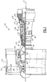
- Figure 3 is a cross-sectional view of the mid-turbine frame 57 taken along line 3-3 of Figure 2 .
- a hollow spoke 65A is one example of the hollow spokes 65 shown in Figure 2 .
- the hollow spoke 65A extends from the outer frame case 62 through the airfoil 59 to the inner frame case 64.
- the airfoil 59 extends from an outer platform 78 to an inner platform 80.
- the airfoil 59, the outer platform 78, and the inner platform 80 are integrally formed, and are all positioned radially inward of the outer frame case 62 and radially outward of the inner frame case 64.
- the airfoil 59, the outer platform 78, and the inner platform 80 define a portion of the core flow path C at the mid-turbine frame 57.
- the airfoil 59 extends axially from a leading edge 82 to a trailing edge 84.
- the airfoil 59 is oblong so as to be longer in the axial direction than in the circumferential direction.
- the airfoil 59 has a hollow interior 86, which is also relatively narrow in a chordal direction.
- the hollow spoke 65A includes a tie rod 90A and the retaining nut 92.
- the tie rod 90A is an elongated hollow tube that includes a threaded surface 94 at a radially outer end and a flange 96 at a radially inner end.
- the threaded surface 94 is on an outer surface 98 of the tie rod 90A.
- An inner passage surface 100 of the tie rod 90A defines an inlet passage 118 through the tie rod 90A.
- the tie rod 90A tapers along its length from the flange 96 at its radially inner end to the threaded surface 94 at its radially outer end.
- the retaining nut 92 includes a threaded surface 102 at a radially inner end of the retaining nut 92 and a flange 104 at a radially outer end of the retaining nut 92.
- the threaded surface 102 is on an inner surface 106 of the retaining nut 92.
- the flange 104 extends outward from an outer surface 108 of the retaining nut 92.
- the flange 96 of the tie rod 90A abuts against the inner frame case 64 so that the inner passage surface 100 aligns with a hole 110A in the inner frame case 64.
- the flange 96 is attached to the inner frame case 64 via threaded fasteners 112, such as bolts.
- the retaining nut 92 extends through a hole 114 in the outer frame case 62 such that the flange 104 abuts against the outer diameter surface 66 of the outer frame case 62.
- the flange 104 is attached to the outer frame case 62 via a bolt 116.
- the bolt 116 extends through the flange 104 into the outer frame case 62.
- the tie rod 90A is threaded into the retaining nut 92 to attach the tie rod 90A to the retaining nut 92.
- a portion but not all of the threaded surface 94 overlaps with a portion but not all of the threaded surface 102.
- the tie rod 90A is inserted through the hollow interior 86 of the airfoil 59 in a direction from radially inward to radially outward.
- the inner frame case 64 is then positioned radially inward of the tie rod 90A and attached to the tie rod 90A by the threaded fasteners 112.
- the retaining nut 92 is then inserted through the hole 114 and threadedly engaged with the tie rod 90A.
- the retaining nut 92 can be tightened, as desired, in a manner described below.
- the bolt 116 is inserted to fix the retaining nut 92 to the outer frame case 62 to prevent the retaining nut 92 from rotating and loosening.
- the threaded connection between the retaining nut 92 and the tie rod 90A is variable.
- the retaining nut 92 does not bottom out at any particular point when threaded on the tie rod 90A. This allows the retaining nut 92 to be threaded on the tie rod 90A to an extent determined during assembly, not predetermined prior to assembly. This allows the hollow spoke 65A, and the mid-turbine frame 57 in general, to be relatively insensitive to manufacturing tolerances.
- the inlet passage 118 branches off between a first branch 120 extending into a bearing support cavity 122 and a second branch 124 extending into a low-rotor cavity 126.
- the first branch 120 extends in a radially inward direction through the inner frame case 64.
- a plug 128 is aligned with the first branch 120 and is located in an opening 130 in the hollow spoke 65A adjacent the outer diameter surface 70 of the inner frame case 64.
- the plug 128 includes an opening 129 having a conical radially outer portion that tapers to a cylindrical channel on a radially inner side.
- the cylindrical channel of the plug 128 includes a diameter D1 that is smaller than a diameter D2 defined by the inner passage surface 100.
- the plug 128 includes a diameter D1, however, the diameter D1 could be any dimension that is smaller than the dimension D2 in order to control the amount of cooling airflow that travels into the bearing support cavity 122.
- the plug 128 is shown contacting the hollow spoke 65a and the inner frame case 64, the plug 128 could be located anywhere within the first branch 120.
- the plug 128 could be solid and prevent the cooling airflow from entering the bearing support cavity 122 so the entire cooling airflow must travel through the second branch 124.
- the opening 130 in the tie rod 90A could be reduced to the diameter D1 so that the plug 128 could be eliminated.
- the second branch 124 extends in an axially downstream direction perpendicular to the first branch 120. Although the second branch 124 is shown being perpendicular to the first branch 120, the second branch 124 could be within 30 degrees of being perpendicular to the first branch 120.
- the second branch 124 is in fluid communication with the low rotor cavity through to a fitting 132 that extends through the inner frame case 64 and connects to a swirler tube 142.
- the fitting 132 includes a transfer tube 134 pressed, welded, or brazed into an opening 138 in the hollow spoke 65A on a first end and engages a cup boss 136 on a second end.
- a piston ring creates a seal between an outer diameter of the transfer tube 134 and the cup boss 136.
- the cup boss 136 is fastened to the inner frame case 64 with fasteners 140 and is aligned with a hole 110B in the inner frame case 64.
- the fasteners 140 also secure the swirler tube 142 to an opposite side of the inner frame case 64 from the cup boss 136.
- the swirler tube 142 directs the cooling airflow into the low rotor cavity in the direction of rotation of the low rotor to reduce turning and aerodynamic losses in the cooling airflow. By pre-swirling the cooling air flow prior to entering the low-rotor cavity 126, the heat up of the cooling air flow is reduced which lowers a temperature of the low-rotor cavity.
- a restricting ring 144 is located between the swirler tube 142 and the inner diameter surface 72.
- the restricting ring 144 includes a diameter D3 which is smaller than a diameter D4 of the second branch 124.
- the restricting ring 144 restricts the amount of cooling airflow through the second branch 124 to aid in dividing the amount of cooling airflow traveling into the bearing support cavity 122 and the low-rotor cavity 126.
- the restricting ring 144 is shown between the swirler tube 142 and the inner frame case 64, the restricting ring 144 could be located anywhere within the second branch 124 to reduce the cooling airflow into the low-rotor cavity 126.
- a portion of the second branch 124 may include a portion with a reduced diameter, such as reducing a diameter of the second branch 124 extending through the transfer tube 134, the cup boss 136, or the hole 110B to meter the cooling airflow.
- the a first portion of cooling airflow travels into the bearing support cavity 122 and a second portion of cooling airflow travels into the low-rotor cavity 126, with the second portion being greater than the first portion.
- a connectivity hole 146 is located in the inner frame case 64.
- the connectivity hole 146 fluidly connects a mid-turbine frame cavity 147 and the low-rotor cavity to supply cooling airflow from the mid-turbine frame cavity 147 without having the cooling airflow mix in the bearing support cavity 122.
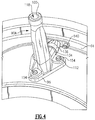
- the tie rod 90A includes bushing openings 150 in the flange 96 that align with a corresponding fastener opening 152 in the inner frame case 64.
- Bushings 154 are placed within the bushing openings 150 in the tie rod 90A.
- the bushings 154 include a flange 162 and a cylindrical portion 164 extending from the flange 162.
- a threaded bushing fastener opening 160 extends through the flange 162 and the cylindrical portion 164 of the bushing 154 and aligns with the fastener opening 152 in the inner frame case 64.
- the threaded openings 160 and the fastener openings 152 accept the threaded fasteners 112.
- the bushing 154 may be made of a dissimilar material from the tie rod 90A.
- the bushing 154 includes a tab 156 having an edge with a radius that extends from the flange 162 and prevents rotation of the bushing 154 relative to the tie rod 90A during installation or disassembly by engaging a portion 158 of the tie rod 90A.
- an axial length A1 of the bushing opening 150 is larger than an axial length A2 of the cylindrical portion 164 on the bushing 154.
- the axial length A2 of the cylindrical portion 164 of the bushing 154 extends approximately 80% to 95% of the axial length A1 of the bushing opening 150. Because the bushing 154 contacts a significant portion of the threaded fastener 112, heat that accumulates in the threaded fastener 112 can be dissipated through the bushing 154 to prevent the threaded fastener 112 from creeping and reducing the roundness and stiffness of the mid-turbine frame 57.
- the threaded fastener 112 may protrude from the bushing 154 or alternatively may be recessed within the bushing 154 to reduce the amount of radiant heat that may reach the threaded fastener 112.
Landscapes
- Engineering & Computer Science (AREA)
- Mechanical Engineering (AREA)
- General Engineering & Computer Science (AREA)
- Chemical & Material Sciences (AREA)
- Combustion & Propulsion (AREA)
- Physics & Mathematics (AREA)
- Fluid Mechanics (AREA)
- Turbine Rotor Nozzle Sealing (AREA)
- Structures Of Non-Positive Displacement Pumps (AREA)
Claims (7)
- Mittelturbinenrahmen (57) eines Gasturbinentriebwerks (20), wobei der Mittelturbinenrahmen (57) eine Befestigungsmittelbaugruppe umfasst, wobei die Befestigungsmittelbaugruppe Folgendes umfasst:ein inneres Rahmengehäuse (64), das eine Befestigungsmittelöffnung (152) beinhaltet;eine Zugstange (90A), die einen Flansch (96) aufweist und eine Buchsenöffnung (150) in dem Flansch (96) beinhaltet;eine Gewindebuchse (154), die mindestens teilweise innerhalb der Buchsenöffnung (150) angeordnet ist, wobei die Buchse (154) einen Flansch (162), einen zylindrischen Abschnitt (164) undeine Gewindebuchsenbefestigungsmittelöffnung (160) beinhaltet,die sich durch den Flansch (162) und den zylindrischen Abschnitt (164) erstreckt und auf die Befestigungsmittelöffnung (152) ausgerichtet ist; undein Befestigungsmittel (112), das sich durch die Befestigungsmittelöffnung (152) erstreckt und die Gewindebuchsenbefestigungsmittelöffnung (160) in Eingriff nimmt, wobei die Gewindebuchse (154), durch Kontakt mit dem Befestigungsmittel (112), so konfiguriert ist, dass sie Wärme von dem Befestigungsmittel (112) abführt, um zu verhindern, dass das Befestigungsmittel (112) kriecht;dadurch gekennzeichnet, dassder Flansch (162) eine Lasche (156) beinhaltet, wobei die Lasche (156) einen Rand beinhaltet, der einen Radius aufweist, der sich von dem Flansch (162) aus erstreckt, um einen Abschnitt (158) der Zugstange (90A) in Eingriff zu nehmen, um zu verhindern,dass sich die Buchse (154) relativ zur Zugstange (90A) während des Einbaus oder Ausbaus dreht.
- Mittelturbinenrahmen (57) nach Anspruch 1, wobei die Zugstange (90A) aus einem ersten Material hergestellt ist und die Buchse (154) aus einem zweiten verschiedenen Material hergestellt ist.
- Mittelturbinenrahmen nach Anspruch 1 oder 2, wobei sich der zylindrische Abschnitt (164) innerhalb der Buchsenöffnung (150) erstreckt.
- Mittelturbinenrahmen nach einem der vorstehenden Ansprüche, wobei die Buchsenöffnung (150) eine erste axiale Länge (A1) beinhaltet und der zylindrische Abschnitt (164) eine zweite axiale Länge (A2) beinhaltet, wobei die erste axiale Länge (A1) größer als die zweite axiale Länge (A2) ist.
- Mittelturbinenrahmen nach Anspruch 4, wobei die zweite axiale Länge (A2) zwischen 80 % und 95 % der ersten axialen Länge (A1) beträgt.
- Gasturbinentriebwerk (20), den Mittelturbinenrahmen (57) nach einem der vorstehenden Ansprüche umfassend, der axial zwischen einer ersten Turbine (46) und einer zweiten Turbine (54) angeordnet ist.
- Verfahren zum Kühlen eines Abschnitts eines Gasturbinentriebwerks (20), wobei das Gasturbinentriebwerk (20) den Mittelturbinenrahmen (57) nach einem der Ansprüche 1 bis 5 umfasst, wobei das Verfahren Folgendes umfasst:Fixieren der Zugstange (90A) relativ zu dem inneren Rahmengehäuse (64) mit dem Befestigungsmittel (112);Verhindern des Drehens der Buchse (154) relativ zur Zugstange (90A) während des Einbaus oder Ausbaus durch Ineingriffnehmen des Rands der Lasche (156) mit dem Abschnitt (158) der Zugstange (90A);Berühren des Befestigungsmittels (112) mit der Buchse (154); undAbführen von Wärme von dem Befestigungsmittel (112) durch die Buchse (154), um ein Kriechen des Befestigungsmittels (112) zu verhindern.
Applications Claiming Priority (1)
| Application Number | Priority Date | Filing Date | Title |
|---|---|---|---|
| US14/612,469 US10392974B2 (en) | 2015-02-03 | 2015-02-03 | Mid-turbine frame assembly |
Publications (2)
| Publication Number | Publication Date |
|---|---|
| EP3054100A1 EP3054100A1 (de) | 2016-08-10 |
| EP3054100B1 true EP3054100B1 (de) | 2021-12-15 |
Family
ID=55299341
Family Applications (1)
| Application Number | Title | Priority Date | Filing Date |
|---|---|---|---|
| EP16153908.5A Active EP3054100B1 (de) | 2015-02-03 | 2016-02-02 | Befestigungsanordnung in einer mittelturbinenrahmenanordnung |
Country Status (2)
| Country | Link |
|---|---|
| US (2) | US10392974B2 (de) |
| EP (1) | EP3054100B1 (de) |
Families Citing this family (9)
| Publication number | Priority date | Publication date | Assignee | Title |
|---|---|---|---|---|
| US9915170B2 (en) * | 2015-03-20 | 2018-03-13 | United Technologies Corporation | Cooling passages for a mid-turbine frame |
| US10443449B2 (en) | 2015-07-24 | 2019-10-15 | Pratt & Whitney Canada Corp. | Spoke mounting arrangement |
| US10920612B2 (en) | 2015-07-24 | 2021-02-16 | Pratt & Whitney Canada Corp. | Mid-turbine frame spoke cooling system and method |
| US10247035B2 (en) | 2015-07-24 | 2019-04-02 | Pratt & Whitney Canada Corp. | Spoke locking architecture |
| GB2551777B (en) * | 2016-06-30 | 2018-09-12 | Rolls Royce Plc | A stator vane arrangement and a method of casting a stator vane arrangement |
| US11346249B2 (en) * | 2019-03-05 | 2022-05-31 | Pratt & Whitney Canada Corp. | Gas turbine engine with feed pipe for bearing housing |
| FR3110201B1 (fr) * | 2020-05-15 | 2022-04-08 | Safran Aircraft Engines | Carter d’échappement de turbomachine |
| GB202018430D0 (en) * | 2020-11-24 | 2021-01-06 | Rolls Royce Plc | Support assembly for gas turbine engine |
| US11486271B1 (en) * | 2021-10-15 | 2022-11-01 | Pratt & Whitney Canada Corp. | Adjustable mount for engine accessory |
Citations (2)
| Publication number | Priority date | Publication date | Assignee | Title |
|---|---|---|---|---|
| US20030118399A1 (en) * | 2001-12-21 | 2003-06-26 | Schilling Jan Christopher | Removable stud for joining casing flanges |
| EP3045671A1 (de) * | 2015-01-16 | 2016-07-20 | United Technologies Corporation | Kühlkanäle für einen mittelturbinenrahmen |
Family Cites Families (18)
| Publication number | Priority date | Publication date | Assignee | Title |
|---|---|---|---|---|
| US6439841B1 (en) | 2000-04-29 | 2002-08-27 | General Electric Company | Turbine frame assembly |
| US7195447B2 (en) | 2004-10-29 | 2007-03-27 | General Electric Company | Gas turbine engine and method of assembling same |
| DE602005001503T2 (de) | 2005-05-04 | 2008-03-06 | Wen-Ya Yeh | Schwenkvorrichtung für Scheren |
| KR100709948B1 (ko) | 2005-06-30 | 2007-04-25 | 삼성광주전자 주식회사 | 밀폐형 압축기 |
| US7797946B2 (en) | 2006-12-06 | 2010-09-21 | United Technologies Corporation | Double U design for mid-turbine frame struts |
| US8091371B2 (en) | 2008-11-28 | 2012-01-10 | Pratt & Whitney Canada Corp. | Mid turbine frame for gas turbine engine |
| US8061969B2 (en) | 2008-11-28 | 2011-11-22 | Pratt & Whitney Canada Corp. | Mid turbine frame system for gas turbine engine |
| US8267630B2 (en) * | 2009-07-13 | 2012-09-18 | United Technologies Corporation | Threaded flanged bushing for fastening applications |
| US8500392B2 (en) | 2009-10-01 | 2013-08-06 | Pratt & Whitney Canada Corp. | Sealing for vane segments |
| US8371127B2 (en) | 2009-10-01 | 2013-02-12 | Pratt & Whitney Canada Corp. | Cooling air system for mid turbine frame |
| US9896966B2 (en) * | 2011-08-29 | 2018-02-20 | United Technologies Corporation | Tie rod for a gas turbine engine |
| US9200536B2 (en) | 2011-10-17 | 2015-12-01 | United Technologies Corporation | Mid turbine frame (MTF) for a gas turbine engine |
| US8901517B2 (en) * | 2012-06-29 | 2014-12-02 | Xerox Corporation | Fluorescent security phase change ink |
| US9587514B2 (en) | 2012-07-13 | 2017-03-07 | United Technologies Corporation | Vane insertable tie rods with keyed connections |
| US9217371B2 (en) | 2012-07-13 | 2015-12-22 | United Technologies Corporation | Mid-turbine frame with tensioned spokes |
| US9482115B2 (en) | 2012-08-23 | 2016-11-01 | United Technologies Corporation | Turbine engine support assembly including self anti-rotating bushing |
| WO2014052007A1 (en) | 2012-09-28 | 2014-04-03 | United Technologies Corporation | Mid-turbine frame with fairing attachment |
| US9890659B2 (en) | 2013-02-11 | 2018-02-13 | United Technologies Corporation | Mid-turbine frame vane assembly support with retention unit |
-
2015
- 2015-02-03 US US14/612,469 patent/US10392974B2/en active Active
-
2016
- 2016-02-02 EP EP16153908.5A patent/EP3054100B1/de active Active
-
2019
- 2019-05-30 US US16/426,707 patent/US10961870B2/en active Active
Patent Citations (2)
| Publication number | Priority date | Publication date | Assignee | Title |
|---|---|---|---|---|
| US20030118399A1 (en) * | 2001-12-21 | 2003-06-26 | Schilling Jan Christopher | Removable stud for joining casing flanges |
| EP3045671A1 (de) * | 2015-01-16 | 2016-07-20 | United Technologies Corporation | Kühlkanäle für einen mittelturbinenrahmen |
Also Published As
| Publication number | Publication date |
|---|---|
| US10961870B2 (en) | 2021-03-30 |
| EP3054100A1 (de) | 2016-08-10 |
| US20190316491A1 (en) | 2019-10-17 |
| US10392974B2 (en) | 2019-08-27 |
| US20160222827A1 (en) | 2016-08-04 |
Similar Documents
| Publication | Publication Date | Title |
|---|---|---|
| EP3054101B1 (de) | Kühlkanäle für einen mittelturbinenrahmen in einem gasturbinentriebwerk | |
| EP3054100B1 (de) | Befestigungsanordnung in einer mittelturbinenrahmenanordnung | |
| EP3045671B1 (de) | Kühlkanäle für einen mittelturbinenrahmen | |
| EP3045672B1 (de) | Kühlkanäle für einen mittelturbinenrahmen | |
| EP3045668B1 (de) | Kühlkanäle für einen mittelturbinenrahmen | |
| EP3067522B1 (de) | Kühlkanäle für einen mittelturbinenrahmen | |
| EP3070273B1 (de) | Kühlkanäle für einen mittelturbinenrahmen eines gasturbinentriebwerks | |
| EP3045683B1 (de) | Kühlkanäle für einen mittelturbinenrahmen | |
| EP3045670B1 (de) | Kühlkanäle für einen mittelturbinenrahmen | |
| EP3070272B1 (de) | Kühlkanäle für ein turbinen-zwischengehäuse | |
| EP3054102B1 (de) | Mittelturbinenrahmenbaugruppe mit kühlkanälen für ein gasturbinentriebwerk | |
| EP3045669B1 (de) | Kühlkanäle für einen mittelturbinenrahmen | |
| US9951624B2 (en) | Clinch nut bolt hole geometry | |
| EP3045682B1 (de) | Zugstrebe für einen mittelturbinenrahmen |
Legal Events
| Date | Code | Title | Description |
|---|---|---|---|
| PUAI | Public reference made under article 153(3) epc to a published international application that has entered the european phase |
Free format text: ORIGINAL CODE: 0009012 |
|
| AK | Designated contracting states |
Kind code of ref document: A1 Designated state(s): AL AT BE BG CH CY CZ DE DK EE ES FI FR GB GR HR HU IE IS IT LI LT LU LV MC MK MT NL NO PL PT RO RS SE SI SK SM TR |
|
| AX | Request for extension of the european patent |
Extension state: BA ME |
|
| RAP1 | Party data changed (applicant data changed or rights of an application transferred) |
Owner name: UNITED TECHNOLOGIES CORPORATION |
|
| STAA | Information on the status of an ep patent application or granted ep patent |
Free format text: STATUS: REQUEST FOR EXAMINATION WAS MADE |
|
| 17P | Request for examination filed |
Effective date: 20170208 |
|
| RBV | Designated contracting states (corrected) |
Designated state(s): AL AT BE BG CH CY CZ DE DK EE ES FI FR GB GR HR HU IE IS IT LI LT LU LV MC MK MT NL NO PL PT RO RS SE SI SK SM TR |
|
| STAA | Information on the status of an ep patent application or granted ep patent |
Free format text: STATUS: EXAMINATION IS IN PROGRESS |
|
| 17Q | First examination report despatched |
Effective date: 20190424 |
|
| STAA | Information on the status of an ep patent application or granted ep patent |
Free format text: STATUS: EXAMINATION IS IN PROGRESS |
|
| RAP1 | Party data changed (applicant data changed or rights of an application transferred) |
Owner name: RAYTHEON TECHNOLOGIES CORPORATION |
|
| GRAP | Despatch of communication of intention to grant a patent |
Free format text: ORIGINAL CODE: EPIDOSNIGR1 |
|
| STAA | Information on the status of an ep patent application or granted ep patent |
Free format text: STATUS: GRANT OF PATENT IS INTENDED |
|
| INTG | Intention to grant announced |
Effective date: 20210629 |
|
| GRAS | Grant fee paid |
Free format text: ORIGINAL CODE: EPIDOSNIGR3 |
|
| GRAA | (expected) grant |
Free format text: ORIGINAL CODE: 0009210 |
|
| STAA | Information on the status of an ep patent application or granted ep patent |
Free format text: STATUS: THE PATENT HAS BEEN GRANTED |
|
| AK | Designated contracting states |
Kind code of ref document: B1 Designated state(s): AL AT BE BG CH CY CZ DE DK EE ES FI FR GB GR HR HU IE IS IT LI LT LU LV MC MK MT NL NO PL PT RO RS SE SI SK SM TR |
|
| REG | Reference to a national code |
Ref country code: GB Ref legal event code: FG4D Ref country code: CH Ref legal event code: EP |
|
| REG | Reference to a national code |
Ref country code: IE Ref legal event code: FG4D Ref country code: DE Ref legal event code: R096 Ref document number: 602016067301 Country of ref document: DE |
|
| REG | Reference to a national code |
Ref country code: AT Ref legal event code: REF Ref document number: 1455640 Country of ref document: AT Kind code of ref document: T Effective date: 20220115 |
|
| REG | Reference to a national code |
Ref country code: LT Ref legal event code: MG9D |
|
| REG | Reference to a national code |
Ref country code: NL Ref legal event code: MP Effective date: 20211215 |
|
| PG25 | Lapsed in a contracting state [announced via postgrant information from national office to epo] |
Ref country code: RS Free format text: LAPSE BECAUSE OF FAILURE TO SUBMIT A TRANSLATION OF THE DESCRIPTION OR TO PAY THE FEE WITHIN THE PRESCRIBED TIME-LIMIT Effective date: 20211215 Ref country code: LT Free format text: LAPSE BECAUSE OF FAILURE TO SUBMIT A TRANSLATION OF THE DESCRIPTION OR TO PAY THE FEE WITHIN THE PRESCRIBED TIME-LIMIT Effective date: 20211215 Ref country code: FI Free format text: LAPSE BECAUSE OF FAILURE TO SUBMIT A TRANSLATION OF THE DESCRIPTION OR TO PAY THE FEE WITHIN THE PRESCRIBED TIME-LIMIT Effective date: 20211215 Ref country code: BG Free format text: LAPSE BECAUSE OF FAILURE TO SUBMIT A TRANSLATION OF THE DESCRIPTION OR TO PAY THE FEE WITHIN THE PRESCRIBED TIME-LIMIT Effective date: 20220315 |
|
| REG | Reference to a national code |
Ref country code: AT Ref legal event code: MK05 Ref document number: 1455640 Country of ref document: AT Kind code of ref document: T Effective date: 20211215 |
|
| PG25 | Lapsed in a contracting state [announced via postgrant information from national office to epo] |
Ref country code: SE Free format text: LAPSE BECAUSE OF FAILURE TO SUBMIT A TRANSLATION OF THE DESCRIPTION OR TO PAY THE FEE WITHIN THE PRESCRIBED TIME-LIMIT Effective date: 20211215 Ref country code: NO Free format text: LAPSE BECAUSE OF FAILURE TO SUBMIT A TRANSLATION OF THE DESCRIPTION OR TO PAY THE FEE WITHIN THE PRESCRIBED TIME-LIMIT Effective date: 20220315 Ref country code: LV Free format text: LAPSE BECAUSE OF FAILURE TO SUBMIT A TRANSLATION OF THE DESCRIPTION OR TO PAY THE FEE WITHIN THE PRESCRIBED TIME-LIMIT Effective date: 20211215 Ref country code: HR Free format text: LAPSE BECAUSE OF FAILURE TO SUBMIT A TRANSLATION OF THE DESCRIPTION OR TO PAY THE FEE WITHIN THE PRESCRIBED TIME-LIMIT Effective date: 20211215 Ref country code: GR Free format text: LAPSE BECAUSE OF FAILURE TO SUBMIT A TRANSLATION OF THE DESCRIPTION OR TO PAY THE FEE WITHIN THE PRESCRIBED TIME-LIMIT Effective date: 20220316 |
|
| PG25 | Lapsed in a contracting state [announced via postgrant information from national office to epo] |
Ref country code: NL Free format text: LAPSE BECAUSE OF FAILURE TO SUBMIT A TRANSLATION OF THE DESCRIPTION OR TO PAY THE FEE WITHIN THE PRESCRIBED TIME-LIMIT Effective date: 20211215 |
|
| PG25 | Lapsed in a contracting state [announced via postgrant information from national office to epo] |
Ref country code: SM Free format text: LAPSE BECAUSE OF FAILURE TO SUBMIT A TRANSLATION OF THE DESCRIPTION OR TO PAY THE FEE WITHIN THE PRESCRIBED TIME-LIMIT Effective date: 20211215 Ref country code: SK Free format text: LAPSE BECAUSE OF FAILURE TO SUBMIT A TRANSLATION OF THE DESCRIPTION OR TO PAY THE FEE WITHIN THE PRESCRIBED TIME-LIMIT Effective date: 20211215 Ref country code: RO Free format text: LAPSE BECAUSE OF FAILURE TO SUBMIT A TRANSLATION OF THE DESCRIPTION OR TO PAY THE FEE WITHIN THE PRESCRIBED TIME-LIMIT Effective date: 20211215 Ref country code: PT Free format text: LAPSE BECAUSE OF FAILURE TO SUBMIT A TRANSLATION OF THE DESCRIPTION OR TO PAY THE FEE WITHIN THE PRESCRIBED TIME-LIMIT Effective date: 20220418 Ref country code: ES Free format text: LAPSE BECAUSE OF FAILURE TO SUBMIT A TRANSLATION OF THE DESCRIPTION OR TO PAY THE FEE WITHIN THE PRESCRIBED TIME-LIMIT Effective date: 20211215 Ref country code: EE Free format text: LAPSE BECAUSE OF FAILURE TO SUBMIT A TRANSLATION OF THE DESCRIPTION OR TO PAY THE FEE WITHIN THE PRESCRIBED TIME-LIMIT Effective date: 20211215 Ref country code: CZ Free format text: LAPSE BECAUSE OF FAILURE TO SUBMIT A TRANSLATION OF THE DESCRIPTION OR TO PAY THE FEE WITHIN THE PRESCRIBED TIME-LIMIT Effective date: 20211215 |
|
| PG25 | Lapsed in a contracting state [announced via postgrant information from national office to epo] |
Ref country code: PL Free format text: LAPSE BECAUSE OF FAILURE TO SUBMIT A TRANSLATION OF THE DESCRIPTION OR TO PAY THE FEE WITHIN THE PRESCRIBED TIME-LIMIT Effective date: 20211215 Ref country code: AT Free format text: LAPSE BECAUSE OF FAILURE TO SUBMIT A TRANSLATION OF THE DESCRIPTION OR TO PAY THE FEE WITHIN THE PRESCRIBED TIME-LIMIT Effective date: 20211215 |
|
| REG | Reference to a national code |
Ref country code: DE Ref legal event code: R097 Ref document number: 602016067301 Country of ref document: DE |
|
| PG25 | Lapsed in a contracting state [announced via postgrant information from national office to epo] |
Ref country code: MC Free format text: LAPSE BECAUSE OF FAILURE TO SUBMIT A TRANSLATION OF THE DESCRIPTION OR TO PAY THE FEE WITHIN THE PRESCRIBED TIME-LIMIT Effective date: 20211215 Ref country code: IS Free format text: LAPSE BECAUSE OF FAILURE TO SUBMIT A TRANSLATION OF THE DESCRIPTION OR TO PAY THE FEE WITHIN THE PRESCRIBED TIME-LIMIT Effective date: 20220415 |
|
| REG | Reference to a national code |
Ref country code: CH Ref legal event code: PL |
|
| PLBE | No opposition filed within time limit |
Free format text: ORIGINAL CODE: 0009261 |
|
| STAA | Information on the status of an ep patent application or granted ep patent |
Free format text: STATUS: NO OPPOSITION FILED WITHIN TIME LIMIT |
|
| REG | Reference to a national code |
Ref country code: BE Ref legal event code: MM Effective date: 20220228 |
|
| PG25 | Lapsed in a contracting state [announced via postgrant information from national office to epo] |
Ref country code: LU Free format text: LAPSE BECAUSE OF NON-PAYMENT OF DUE FEES Effective date: 20220202 Ref country code: DK Free format text: LAPSE BECAUSE OF FAILURE TO SUBMIT A TRANSLATION OF THE DESCRIPTION OR TO PAY THE FEE WITHIN THE PRESCRIBED TIME-LIMIT Effective date: 20211215 Ref country code: AL Free format text: LAPSE BECAUSE OF FAILURE TO SUBMIT A TRANSLATION OF THE DESCRIPTION OR TO PAY THE FEE WITHIN THE PRESCRIBED TIME-LIMIT Effective date: 20211215 |
|
| 26N | No opposition filed |
Effective date: 20220916 |
|
| PG25 | Lapsed in a contracting state [announced via postgrant information from national office to epo] |
Ref country code: SI Free format text: LAPSE BECAUSE OF FAILURE TO SUBMIT A TRANSLATION OF THE DESCRIPTION OR TO PAY THE FEE WITHIN THE PRESCRIBED TIME-LIMIT Effective date: 20211215 |
|
| PG25 | Lapsed in a contracting state [announced via postgrant information from national office to epo] |
Ref country code: LI Free format text: LAPSE BECAUSE OF NON-PAYMENT OF DUE FEES Effective date: 20220228 Ref country code: IE Free format text: LAPSE BECAUSE OF NON-PAYMENT OF DUE FEES Effective date: 20220202 Ref country code: CH Free format text: LAPSE BECAUSE OF NON-PAYMENT OF DUE FEES Effective date: 20220228 |
|
| PG25 | Lapsed in a contracting state [announced via postgrant information from national office to epo] |
Ref country code: BE Free format text: LAPSE BECAUSE OF NON-PAYMENT OF DUE FEES Effective date: 20220228 |
|
| PG25 | Lapsed in a contracting state [announced via postgrant information from national office to epo] |
Ref country code: IT Free format text: LAPSE BECAUSE OF FAILURE TO SUBMIT A TRANSLATION OF THE DESCRIPTION OR TO PAY THE FEE WITHIN THE PRESCRIBED TIME-LIMIT Effective date: 20211215 |
|
| P01 | Opt-out of the competence of the unified patent court (upc) registered |
Effective date: 20230520 |
|
| PG25 | Lapsed in a contracting state [announced via postgrant information from national office to epo] |
Ref country code: HU Free format text: LAPSE BECAUSE OF FAILURE TO SUBMIT A TRANSLATION OF THE DESCRIPTION OR TO PAY THE FEE WITHIN THE PRESCRIBED TIME-LIMIT; INVALID AB INITIO Effective date: 20160202 |
|
| PG25 | Lapsed in a contracting state [announced via postgrant information from national office to epo] |
Ref country code: MK Free format text: LAPSE BECAUSE OF FAILURE TO SUBMIT A TRANSLATION OF THE DESCRIPTION OR TO PAY THE FEE WITHIN THE PRESCRIBED TIME-LIMIT Effective date: 20211215 Ref country code: CY Free format text: LAPSE BECAUSE OF FAILURE TO SUBMIT A TRANSLATION OF THE DESCRIPTION OR TO PAY THE FEE WITHIN THE PRESCRIBED TIME-LIMIT Effective date: 20211215 |
|
| PGFP | Annual fee paid to national office [announced via postgrant information from national office to epo] |
Ref country code: DE Payment date: 20240123 Year of fee payment: 9 Ref country code: GB Payment date: 20240123 Year of fee payment: 9 |
|
| PGFP | Annual fee paid to national office [announced via postgrant information from national office to epo] |
Ref country code: FR Payment date: 20240123 Year of fee payment: 9 |
|
| PG25 | Lapsed in a contracting state [announced via postgrant information from national office to epo] |
Ref country code: MT Free format text: LAPSE BECAUSE OF FAILURE TO SUBMIT A TRANSLATION OF THE DESCRIPTION OR TO PAY THE FEE WITHIN THE PRESCRIBED TIME-LIMIT Effective date: 20211215 |