EP3045671B1 - Kühlkanäle für einen mittelturbinenrahmen - Google Patents
Kühlkanäle für einen mittelturbinenrahmen Download PDFInfo
- Publication number
- EP3045671B1 EP3045671B1 EP16151371.8A EP16151371A EP3045671B1 EP 3045671 B1 EP3045671 B1 EP 3045671B1 EP 16151371 A EP16151371 A EP 16151371A EP 3045671 B1 EP3045671 B1 EP 3045671B1
- Authority
- EP
- European Patent Office
- Prior art keywords
- mid
- turbine
- spoke
- frame case
- flange
- Prior art date
- Legal status (The legal status is an assumption and is not a legal conclusion. Google has not performed a legal analysis and makes no representation as to the accuracy of the status listed.)
- Active
Links
Images


Classifications
-
- F—MECHANICAL ENGINEERING; LIGHTING; HEATING; WEAPONS; BLASTING
- F01—MACHINES OR ENGINES IN GENERAL; ENGINE PLANTS IN GENERAL; STEAM ENGINES
- F01D—NON-POSITIVE DISPLACEMENT MACHINES OR ENGINES, e.g. STEAM TURBINES
- F01D25/00—Component parts, details, or accessories, not provided for in, or of interest apart from, other groups
- F01D25/08—Cooling; Heating; Heat-insulation
- F01D25/14—Casings modified therefor
-
- F—MECHANICAL ENGINEERING; LIGHTING; HEATING; WEAPONS; BLASTING
- F01—MACHINES OR ENGINES IN GENERAL; ENGINE PLANTS IN GENERAL; STEAM ENGINES
- F01D—NON-POSITIVE DISPLACEMENT MACHINES OR ENGINES, e.g. STEAM TURBINES
- F01D9/00—Stators
- F01D9/06—Fluid supply conduits to nozzles or the like
- F01D9/065—Fluid supply or removal conduits traversing the working fluid flow, e.g. for lubrication-, cooling-, or sealing fluids
-
- F—MECHANICAL ENGINEERING; LIGHTING; HEATING; WEAPONS; BLASTING
- F01—MACHINES OR ENGINES IN GENERAL; ENGINE PLANTS IN GENERAL; STEAM ENGINES
- F01D—NON-POSITIVE DISPLACEMENT MACHINES OR ENGINES, e.g. STEAM TURBINES
- F01D25/00—Component parts, details, or accessories, not provided for in, or of interest apart from, other groups
- F01D25/08—Cooling; Heating; Heat-insulation
- F01D25/12—Cooling
-
- F—MECHANICAL ENGINEERING; LIGHTING; HEATING; WEAPONS; BLASTING
- F01—MACHINES OR ENGINES IN GENERAL; ENGINE PLANTS IN GENERAL; STEAM ENGINES
- F01D—NON-POSITIVE DISPLACEMENT MACHINES OR ENGINES, e.g. STEAM TURBINES
- F01D25/00—Component parts, details, or accessories, not provided for in, or of interest apart from, other groups
- F01D25/16—Arrangement of bearings; Supporting or mounting bearings in casings
- F01D25/162—Bearing supports
-
- F—MECHANICAL ENGINEERING; LIGHTING; HEATING; WEAPONS; BLASTING
- F01—MACHINES OR ENGINES IN GENERAL; ENGINE PLANTS IN GENERAL; STEAM ENGINES
- F01D—NON-POSITIVE DISPLACEMENT MACHINES OR ENGINES, e.g. STEAM TURBINES
- F01D25/00—Component parts, details, or accessories, not provided for in, or of interest apart from, other groups
- F01D25/24—Casings; Casing parts, e.g. diaphragms, casing fastenings
-
- F—MECHANICAL ENGINEERING; LIGHTING; HEATING; WEAPONS; BLASTING
- F05—INDEXING SCHEMES RELATING TO ENGINES OR PUMPS IN VARIOUS SUBCLASSES OF CLASSES F01-F04
- F05D—INDEXING SCHEME FOR ASPECTS RELATING TO NON-POSITIVE-DISPLACEMENT MACHINES OR ENGINES, GAS-TURBINES OR JET-PROPULSION PLANTS
- F05D2220/00—Application
- F05D2220/30—Application in turbines
- F05D2220/32—Application in turbines in gas turbines
-
- Y—GENERAL TAGGING OF NEW TECHNOLOGICAL DEVELOPMENTS; GENERAL TAGGING OF CROSS-SECTIONAL TECHNOLOGIES SPANNING OVER SEVERAL SECTIONS OF THE IPC; TECHNICAL SUBJECTS COVERED BY FORMER USPC CROSS-REFERENCE ART COLLECTIONS [XRACs] AND DIGESTS
- Y02—TECHNOLOGIES OR APPLICATIONS FOR MITIGATION OR ADAPTATION AGAINST CLIMATE CHANGE
- Y02T—CLIMATE CHANGE MITIGATION TECHNOLOGIES RELATED TO TRANSPORTATION
- Y02T50/00—Aeronautics or air transport
- Y02T50/60—Efficient propulsion technologies, e.g. for aircraft
Definitions
- the present disclosure relates generally to a gas turbine engine, and in particular to a mid-turbine frame (MTF) included in a gas turbine engine.
- MTF mid-turbine frame
- a gas turbine engine typically includes a fan section, a compressor section, a combustor section, and a turbine section. Air entering the compressor section is compressed and delivered into the combustion section where it is mixed with fuel and ignited to generate a high-speed exhaust gas flow. The high-speed exhaust gas flow expands through the turbine section to drive the compressor and the fan section.
- a mid-turbine frame is positioned between a high pressure turbine stage and a low pressure turbine stage of a gas turbine engine.
- the MTF supports one or more bearings and transfers bearing loads from an inner portion of the gas turbine engine to an outer engine frame.
- the MTF also serves to route air from the high pressure turbine stage to the low pressure turbine stage.
- a prior art mid-turbine frame having the features of the preamble to claim 1 is disclosed in US 2013/219919 .
- Other prior art mid-turbine frames are disclosed in EP 2 573 329 and EP 2 565 395 .
- From one aspect of the present invention provides a mid-turbine frame in accordance with claim 1.
- a flange on a radially inner end of the cylindrical portion.
- the flange includes a pair of fastener openings on a downstream end and a single fastener opening on an upstream end.
- the single fastener opening on the upstream end is located at least partially circumferentially between the pair of fastener openings on the downstream end.
- the single fastener opening on the upstream end is located entirely circumferentially between the pair of fastener openings on the downstream end.
- a perimeter of the flange is defined by a downstream edge, a first angled portion and a second angled portion.
- the first angled portion extends at between approximately 28 and 58 degrees relative to the axial direction.
- the second angled portion extends at between approximately 17 and 47 degrees relative to the axial direction.
- a swirler tube is connected to the fitting for directing cooling airflow in a direction of rotation of a low pressure rotor.
- At least one buttress extends between an outer surface of at least one spoke and a flange of at least one spoke.
- the present invention provides a gas turbine engine in accordance with claim 9.
- FIG. 1 schematically illustrates a gas turbine engine 20.
- the gas turbine engine 20 is disclosed herein as a two-spool turbofan that generally incorporates a fan section 22, a compressor section 24, a combustor section 26 and a turbine section 28.
- Alternative engines might include an augmentor section (not shown) among other systems or features.
- the fan section 22 drives air along a bypass flow path B in a bypass duct defined within a nacelle 15, while the compressor section 24 drives air along a core flow path C for compression and communication into the combustor section 26 then expansion through the turbine section 28.
- the exemplary engine 20 generally includes a low speed spool 30 and a high speed spool 32 mounted for rotation about an engine central longitudinal axis A relative to an engine static structure 36 via several bearing systems 38. It should be understood that various bearing systems 38 at various locations may alternatively or additionally be provided, and the location of bearing systems 38 may be varied as appropriate to the application.
- the low speed spool 30 generally includes an inner shaft 40 that interconnects a fan 42, a first (or low) pressure compressor 44 and a first (or low) pressure turbine 46.
- the inner shaft 40 is connected to the fan 42 through a speed change mechanism, which in exemplary gas turbine engine 20 is illustrated as a geared architecture 48 to drive the fan 42 at a lower speed than the low speed spool 30.
- the high speed spool 32 includes an outer shaft 50 that interconnects a second (or high) pressure compressor 52 and a second (or high) pressure turbine 54.
- a combustor 56 is arranged in exemplary gas turbine 20 between the high pressure compressor 52 and the high pressure turbine 54.
- a mid-turbine frame 57 of the engine static structure 36 is arranged generally between the high pressure turbine 54 and the low pressure turbine 46.
- the mid-turbine frame 57 further supports bearing systems 38 in the turbine section 28.
- the inner shaft 40 and the outer shaft 50 are concentric and rotate via bearing systems 38 about the engine central longitudinal axis A which is collinear with their longitudinal axes.
- the core airflow is compressed by the low pressure compressor 44 then the high pressure compressor 52, mixed and burned with fuel in the combustor 56, then expanded over the high pressure turbine 54 and low pressure turbine 46.
- the mid-turbine frame 57 includes airfoils 59 which are in the core airflow path C.
- the turbines 46, 54 rotationally drive the respective low speed spool 30 and high speed spool 32 in response to the expansion.
- gear system 48 may be located aft of combustor section 26 or even aft of turbine section 28, and fan section 22 may be positioned forward or aft of the location of gear system 48.
- the engine 20 in one example is a high-bypass geared aircraft engine.
- the engine 20 bypass ratio is greater than about six (6:1), with an example embodiment being greater than about ten (10:1)
- the geared architecture 48 is an epicyclic gear train, such as a planetary gear system or other gear system, with a gear reduction ratio of greater than about 2.3 (2.3:1)
- the low pressure turbine 46 has a pressure ratio that is greater than about five (5:1).
- the engine 20 bypass ratio is greater than about ten (10:1)
- the fan diameter is significantly larger than that of the low pressure compressor 44
- the low pressure turbine 46 has a pressure ratio that is greater than about five (5:1).
- Low pressure turbine 46 pressure ratio is pressure measured prior to inlet of low pressure turbine 46 as related to the pressure at the outlet of the low pressure turbine 46 prior to an exhaust nozzle.
- the geared architecture 48 may be an epicycle gear train, such as a planetary gear system or other gear system, with a gear reduction ratio of greater than about 2.3 (2.3:1). It should be understood, however, that the above parameters are only exemplary of one embodiment of a geared architecture engine and that the present invention is applicable to other gas turbine engines including direct drive turbofans.
- the fan section 22 of the engine 20 is designed for a particular flight condition -- typically cruise at about 0.8 Mach (274 m/s) and about 35,000 feet (10,668 m).
- "Low fan pressure ratio” is the pressure ratio across the fan blade alone, without a Fan Exit Guide Vane (“FEGV”) system.
- the low fan pressure ratio as disclosed herein according to one non-limiting embodiment is less than about 1.45 (1.45:1).
- "Low corrected fan tip speed” is the actual fan tip speed in ft/sec divided by an industry standard temperature correction of [(Tram °R) / (518.7 °R)] 0.5 .
- the "Low corrected fan tip speed” as disclosed herein according to one non-limiting embodiment is less than about 1150 ft / second (350.5 meters/second).
- the example gas turbine engine includes fan 42 that comprises in one non-limiting embodiment less than about 26 fan blades. In another non-limiting embodiment, fan section 22 includes less than about 20 fan blades. Moreover, in one disclosed embodiment low pressure turbine 46 includes no more than about 6 turbine rotors. In another non-limiting example embodiment low pressure turbine 46 includes about 3 turbine rotors. A ratio between number of fan blades 42 and the number of low pressure turbine rotors is between about 3.3 and about 8.6 (about 3.1:1 and about 8.6:1). The example low pressure turbine 46 provides the driving power to rotate fan section 22 and therefore the relationship between the number of turbine rotors in low pressure turbine 46 and number of blades 42 in fan section 22 disclose an example gas turbine engine 20 with increased power transfer efficiency.
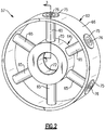
- FIG. 2 is a schematic perspective view of one embodiment of mid-turbine frame 57.
- the schematic view shown in Figure 2 is high level conceptual view and is intended to illustrate relative positioning of various components, but not actual shape of various components.
- the mid-turbine frame 57 includes an outer frame case 62, an inner frame case 64, and a plurality of hollow spokes 65.
- the outer frame case 62 includes an outer diameter surface 66.
- the inner frame case 64 includes an outer diameter surface 70 and an inner diameter surface 72.
- six hollow spokes 65 are distributed evenly around the circumference of the inner frame case 64 to provide structural support between the inner frame case 64 and the outer frame case 62.
- each of the hollow spokes 65 is directly opposite (i.e. 180 degrees from) another of the hollow spokes 65.
- the mid-turbine frame 57 can have an even number of hollow spokes greater than or less than six.
- the inner frame case 64 supports the rotor assembly via the bearing systems 38 (shown in Figure 1 ), and distributes the force from the inner frame case 64 to the outer frame case 62 via the plurality of hollow spokes 65. Attachment of the hollow spokes 65 to the outer frame case 62 is provided at a plurality of bosses 75 located circumferentially around the outer diameter surface 66 of the outer frame case 62.
- attachment of the hollow spokes 65 at the plurality of bosses 75 may be secured by a retaining nut (shown in Figure 3 ) that allows the hollow spokes 65 to be tensioned.
- the hollow spokes 65 can be tensioned via a threaded connection so as to remain in tension during substantially all operating conditions of gas turbine engine 20.
- Apertures 76 formed in each of the plurality of bosses 75 allow cooling airflow to be distributed into a hollow portion of each of the hollow spokes 65. In this way, the cooling airflow is directed from the outer diameter through the hollow portions of the cooled hollow spokes 65 towards the inner frame case 64.
- the cooling airflow can function to cool the hollow spokes 65 and also to cool components radially inward of the inner frame case 64, such as the bearing systems 38.
- Figure 3 is a cross-sectional view of the mid-turbine frame 57 taken along line 3-3 of Figure 2 .
- a hollow spoke 65A is one example of the hollow spokes 65 shown in Figure 2 .
- the hollow spoke 65A extends from the outer frame case 62 through the airfoil 59 to the inner frame case 64.
- the airfoil 59 extends from an outer platform 78 to an inner platform 80.
- the airfoil 59, the outer platform 78, and the inner platform 80 are integrally formed, and are all positioned radially inward of the outer frame case 62 and radially outward of the inner frame case 64.
- the airfoil 59, the outer platform 78, and the inner platform 80 define a portion of the core flow path C at the mid-turbine frame 57.
- the airfoil 59 extends axially from a leading edge 82 to a trailing edge 84.
- the airfoil 59 is oblong so as to be longer in the axial direction than in the circumferential direction.
- the airfoil 59 has a hollow interior 86, which is also relatively narrow in a circumferential direction.
- the hollow spoke 65A includes a tie rod 90A and a retaining nut 92.
- the tie rod 90A is an elongated hollow tube that includes a threaded surface 94 at a radially outer end and a flange 96 at a radially inner end.
- the threaded surface 94 is on an outer surface 98 of the tie rod 90A.
- An inner passage surface 100 of the tie rod 90A defines an inlet passage 118 through the tie rod 90A.
- the tie rod 90A tapers along its length from the flange 96 at its radially inner end to the threaded surface 94 at its radially outer end.
- the retaining nut 92 includes a threaded surface 102 at a radially inner end of the retaining nut 92 and a flange 104 at a radially outer end of the retaining nut 92.
- the threaded surface 102 is on an inner surface 106 of the retaining nut 92.
- the flange 104 extends outward from an outer surface 108 of the retaining nut 92.
- the flange 96 of the tie rod 90A abuts against the inner frame case 64 so that the inner passage surface 100 aligns with a hole 110A in the inner frame case 64.
- the flange 96 is attached to the inner frame case 64 via bolts 112.
- the retaining nut 92 extends through a hole 114 in the outer frame case 62 such that the flange 104 abuts against the outer diameter surface 66 of the outer frame case 62.
- the flange 104 is attached to the outer frame case 62 via a bolt 116.
- the bolt 116 extends through the flange 104 into the outer frame case 62.
- the tie rod 90A is threaded into the retaining nut 92 to attach the tie rod 90A to the retaining nut 92.
- a portion but not all of the threaded surface 94 overlaps with a portion but not all of the threaded surface 102.
- the tie rod 90A is inserted through the hollow interior 86 of the airfoil 59 in a direction from radially inward to radially outward.
- the inner frame case 64 is then positioned radially inward of the tie rod 90A and attached to the tie rod 90A by the bolts 112.
- the retaining nut 92 is then inserted through the hole 114 and threadedly engaged with the tie rod 90A.
- the retaining nut 92 can be tightened, as desired, in a manner described below.
- the bolt 116 is inserted to fix the retaining nut 92 to the outer frame case 62 to prevent the retaining nut 92 from rotating and loosening.
- the threaded connection between the retaining nut 92 and the tie rod 90A is variable.
- the retaining nut 92 does not bottom out at any particular point when threaded on the tie rod 90A. This allows the retaining nut 92 to be threaded on the tie rod 90A to an extent determined during assembly, not predetermined prior to assembly. This allows the hollow spoke 65A, and the mid-turbine frame 57 in general, to be relatively insensitive to manufacturing tolerances.
- the inlet passage 118 branches off between a first branch 120 extending into a bearing support cavity 122 and a second branch 124 extending into a low-rotor cavity 126.
- the bearing support cavity 122 is at least partially defined by the inner frame case 64 and a bearing support member 123.
- the first branch 120 extends in a radially inward direction through the inner frame case 64.
- a plug 128 is aligned with the first branch 120 and is located in an opening 130 in the hollow spoke 65A adjacent the outer diameter surface 70 of the inner frame case 64.
- the plug 128 includes an opening 129 having a conical radially outer portion that tapers to a cylindrical channel on a radially inner side.
- the cylindrical channel of the plug 128 includes a diameter D1 that is smaller than a diameter D2 defined by the inner passage surface 100.
- the plug 128 includes a diameter D1, however, the diameter D1 could be any dimension that is smaller than the dimension D2 in order to control the amount of cooling airflow that travels into the bearing support cavity 122.
- the plug 128 is shown contacting the hollow spoke 65a and the inner frame case 64, the plug 128 could be located anywhere within the first branch 120. Alternatively, the plug 128 could be solid and prevent the cooling airflow from entering the bearing support cavity 122 so the entire cooling airflow must travel through the second branch 124.
- the second branch 124 extends in an axially downstream direction perpendicular to the first branch 120. Although the second branch 124 is shown being perpendicular to the first branch 120, the second branch 124 could be within 20 degrees of being perpendicular to the first branch 120.
- the second branch 124 is in fluid communication with the low rotor cavity through to a fitting 132 that extends through the inner frame case 64 and connects to a swirler tube 142.
- the fitting 132 includes a transfer tube 134 pressed into an opening 138 in the hollow spoke 65A on a first end and engages a cup boss 136 on a second end.
- An O-ring creates a seal between an outer diameter of the transfer tube 134 and the cup boss 136.
- the cup boss 136 is fastened to the inner frame case 64 with fasteners 140 and is aligned with a hole 110B in the inner frame case 64.
- the fasteners 140 also secure the swirler tube 142 to an opposite side of the inner frame case 64 from the cup boss 136.
- the swirler tube 142 directs the cooling airflow into the low rotor cavity in the direction of rotation of the low rotor to reduce turning and aerodynamic losses in the cooling airflow.
- a restricting ring 144 is located between the swirler tube 142 and the inner diameter surface 72.
- the restricting ring 144 includes a diameter D3 which is smaller than a diameter D4 of the second branch 124.
- the restricting ring 144 restricts the amount of cooling airflow through the second branch 124 to aid in dividing the amount of cooling airflow traveling into the bearing support cavity 122 and the low-rotor cavity 126.
- the restricting ring 144 is shown between the swirler tube 142 and the inner frame case 64, the restricting ring 144 could be located anywhere within the second branch 124 to reduce the cooling airflow into the low-rotor cavity 126.
- the a first portion of cooling airflow travels into the bearing support cavity 122 and a second portion of cooling airflow travels into the low-rotor cavity 126, with the second portion being greater than the first portion.
- a cavity connecting opening 146 is located between the bearing support cavity 122 and the low-rotor cavity 126.
- the cavity connecting opening 146 may be removed or blocked to fluidly separate the bearing support cavity 122 from the low-rotor cavity 126. Separating the bearing support cavity 122 from the low-rotor cavity 126 can prevent cooling airflow mixed with oil in the bearing support cavity 122 from entering the low-rotor cavity 126.
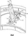
- FIGS 4 and 5 illustrate a perspective view of the tie rod 90A.
- the tie rod 90A includes three fastener openings 150 for securing the tie rod 90A to the inner frame case 64 with the bolts 112.
- Bushings 152 are aligned with the fastener openings 150 and include tabs 154 that prevent rotation of the bushing 152 relative to the tie rod 90A by engaging a portion of the tie rod 90A.
- a first buttress 97 extends between the outer surface 98 of the tie rod 90A and the flange 96 and includes an upper surface at an angle ⁇ relative to the flange 96. In one example, the angle ⁇ is 56 degrees and in another example, the angle ⁇ is between 36 and 76 degrees.
- the flange 96 includes a downstream edge 156, a first angled portion 160, a second angled portion 162, and a perpendicular portion 164 that is perpendicular to the downstream edge 156.
- the downstream edge 156, the first angled portion 160, the second angled portion 162, and the perpendicular portion 164 are connected to each other by a plurality of rounded portions 158 and collectively form a perimeter around the flange 96.
- a pair of fastener openings 150 are located adjacent the downstream edge 156 and a single fastener opening 150 is located adjacent an upstream edge of the flange 96 adjacent the rounded portion 158 that connects the first angled portion 160 to the second angled portion 162.
- upstream and downstream is in reference to the engine axis A unless stated otherwise.
- the single fastener opening 150 adjacent the upstream edge is at least partially circumferentially between the pair of fastener openings 150 located adjacent the downstream edge 156. In another example, the single fastener opening 150 is located entirely circumferentially between the pair of fastener openings 150.
- circumferential or circumferentially is in reference to the engine axis A unless stated otherwise.
- the first angled portion 160 extends at an angle ⁇ relative to the downstream edge 156 and the second angled portion 162 extends at an angle ⁇ relative to the downstream edge 156.
- the angle ⁇ is between approximately 28 and 58 degrees and the angle ⁇ is approximately 17 and 47 degrees.
- the first buttress 97 extends at an angle ⁇ relative to the first angled portion 160.
- the angle ⁇ is 59 degrees and in another example, the angle ⁇ is between 28 and 90 degrees.
- a second buttress 99 extends at an angle ⁇ relative to the second angled portion 162.
- the angle ⁇ is 65 degrees and in another example, the angle ⁇ is between 35 and 95 degrees.
- FIG. 7 illustrates another example tie rod 90A'.
- the tie rod 90A' is similar to the tie rod 90A except where described below or shown in the Figures.
- An inner passage surface 100' defines an inlet passage 118' and extends radially inward and branches at a branch passage 124' extending into the low-rotor cavity 126.
- the branch passage 124' extends in an axially downstream direction perpendicular to the inlet passage 118'. Although the branch passage 124' is shown being perpendicular to the inlet passage 118', the branch passage 124' could be within 20 degrees of being perpendicular to the inlet branch 118'.
- the branch passage 124' is in fluid communication with the low-rotor cavity 126 through to the fitting 132 which extends through the inner frame case 64 and connects to the swirler tube 142.
Landscapes
- Engineering & Computer Science (AREA)
- Mechanical Engineering (AREA)
- General Engineering & Computer Science (AREA)
- Physics & Mathematics (AREA)
- Fluid Mechanics (AREA)
- Turbine Rotor Nozzle Sealing (AREA)
- Structures Of Non-Positive Displacement Pumps (AREA)
Claims (9)
- Mittelturbinenrahmen (57) für ein Gasturbinentriebwerk (20), der Folgendes umfasst:ein äußeres Rahmengehäuse (62);ein inneres Rahmengehäuse (64); undwenigstens eine Speiche (65), die das äußere Rahmengehäuse (62) mit dem inneren Rahmengehäuse (64) verbindet, wobei die Speiche (65) einen Kühlluftströmungskanal (118) einschließt, der zwischen einem ersten Zweig (120), der sich radial zur Verbindung mit einem Lagerstützhohlraum (122) erstreckt, und einem zweiten Zweig (124), der sich axial zur Verbindung mit einem Hohlraum (126) eines Niederdruckrotors erstreckt, abzweigt;dadurch gekennzeichnet, dass er ferner Folgendes umfasst:
ein Formstück, dass den Kühlluftströmungskanal (118) mit dem inneren Rahmengehäuse (64) verbindet, wobei das Formstück ein Übertragungsrohr (134) einschließt, dass die wenigstens eine Speiche (65) mit einer Schalenbefestigung (136) verbindet, und wobei das Übertragungsrohr (134) relativ zu der wenigstens einen Speiche (65) fixiert und relativ zu der Schalenbefestigung (136) beweglich ist. - Mittelturbinenrahmen (57) nach Anspruch 1, ferner umfassend einen Flansch (96) an einem radial inneren Ende des ersten Zweigs (120), wobei der Flansch (96) ein Paar von Befestigungseinrichtungsöffnungen (150) an einem Stromabwärtsende und eine einzige Befestigungseinrichtungsöffnung (150) an einem Stromaufwärtsende einschließt.
- Mittelturbinenrahmen (57) nach Anspruch 2, wobei die einzelne Befestigungseinrichtungsöffnung (150) an dem Stromaufwärtsende wenigstens teilweise in Umfangsrichtung zwischen dem Paar von Befestigungseinrichtungsöffnungen (150) an dem Stromabwärtsende positioniert ist.
- Mittelturbinenrahmen (57) nach Anspruch 2, wobei die einzelne Befestigungseinrichtungsöffnung (150) an dem Stromaufwärtsende vollständig in Umfangsrichtung zwischen dem Paar von Befestigungseinrichtungsöffnungen (150) an dem Stromabwärtsende positioniert ist.
- Mittelturbinenrahmen (57) nach Anspruch 2, 3 oder 4, wobei ein Umfang des Flansches (96) von einer Stromabwärtskante (156), einem ersten abgewinkelten Abschnitt (160) und einem zweiten abgewinkelten Abschnitt (162) definiert wird.
- Mittelturbinenrahmen (57) nach Anspruch 5, wobei der erste abgewinkelte Abschnitt (160) sich bei zwischen 28 und 58 Grad relativ zu der axialen Richtung erstreckt, und der zweite abgewinkelte Bereich (162) sich bei zwischen 17 und 47 Grad relativ zu der axialen Richtung erstreckt.
- Mittelturbinenrahmen (57) nach einem der vorhergehenden Ansprüche, ferner umfassend ein Verwirblerrohr (142), das mit dem Formstück verbunden ist, zum Leiten der Kühlluftströmung in eine Richtung einer Rotation eines Niederdruckrotors.
- Mittelturbinenrahmen (57) nach einem der vorhergehenden Ansprüche, ferner umfassend wenigstens ein Widerlager (97, 99), das sich zwischen einer Außenfläche der wenigstens einen Speiche (65) und einem/dem Flansch (96) der wenigstens einen Speiche (65) erstreckt.
- Gasturbinentriebwerk (20), das Folgendes umfasst:
den Mittelturbinenrahmen (57) nach einem der vorhergehenden Ansprüche, der axial zwischen einer ersten Turbine (54) und einer zweiten Turbine (46) positioniert ist.
Applications Claiming Priority (1)
| Application Number | Priority Date | Filing Date | Title |
|---|---|---|---|
| US14/598,474 US9915171B2 (en) | 2015-01-16 | 2015-01-16 | Cooling passages for a mid-turbine frame |
Publications (2)
| Publication Number | Publication Date |
|---|---|
| EP3045671A1 EP3045671A1 (de) | 2016-07-20 |
| EP3045671B1 true EP3045671B1 (de) | 2018-09-05 |
Family
ID=55129795
Family Applications (1)
| Application Number | Title | Priority Date | Filing Date |
|---|---|---|---|
| EP16151371.8A Active EP3045671B1 (de) | 2015-01-16 | 2016-01-14 | Kühlkanäle für einen mittelturbinenrahmen |
Country Status (2)
| Country | Link |
|---|---|
| US (1) | US9915171B2 (de) |
| EP (1) | EP3045671B1 (de) |
Families Citing this family (12)
| Publication number | Priority date | Publication date | Assignee | Title |
|---|---|---|---|---|
| US10233781B2 (en) * | 2014-02-26 | 2019-03-19 | United Technologies Corporation | Tie rod connection for mid-turbine frame |
| US9856750B2 (en) * | 2015-01-16 | 2018-01-02 | United Technologies Corporation | Cooling passages for a mid-turbine frame |
| US10392974B2 (en) * | 2015-02-03 | 2019-08-27 | United Technologies Corporation | Mid-turbine frame assembly |
| US9915170B2 (en) * | 2015-03-20 | 2018-03-13 | United Technologies Corporation | Cooling passages for a mid-turbine frame |
| US9885254B2 (en) * | 2015-04-24 | 2018-02-06 | United Technologies Corporation | Mid turbine frame including a sealed torque box |
| CA2936182C (en) | 2015-07-24 | 2023-08-15 | Pratt & Whitney Canada Corp. | Mid-turbine frame spoke cooling system and method |
| US10247035B2 (en) | 2015-07-24 | 2019-04-02 | Pratt & Whitney Canada Corp. | Spoke locking architecture |
| US10443449B2 (en) | 2015-07-24 | 2019-10-15 | Pratt & Whitney Canada Corp. | Spoke mounting arrangement |
| US10273812B2 (en) | 2015-12-18 | 2019-04-30 | Pratt & Whitney Canada Corp. | Turbine rotor coolant supply system |
| DE102016217320A1 (de) * | 2016-09-12 | 2018-03-15 | Siemens Aktiengesellschaft | Gasturbine mit getrennter Kühlung für Turbine und Abgasgehäuse |
| US11162622B2 (en) * | 2018-04-27 | 2021-11-02 | Raytheon Technologies Corporation | Wedge adapter seal |
| CN109667669B (zh) * | 2018-12-28 | 2020-08-25 | 中国科学院工程热物理研究所 | 燃气轮机进气机匣 |
Family Cites Families (14)
| Publication number | Priority date | Publication date | Assignee | Title |
|---|---|---|---|---|
| US5272869A (en) * | 1992-12-10 | 1993-12-28 | General Electric Company | Turbine frame |
| GB0026751D0 (en) * | 2000-11-02 | 2000-12-20 | Perkins Engines Co Ltd | Adaptable fluid-flow apparatus |
| US7195447B2 (en) | 2004-10-29 | 2007-03-27 | General Electric Company | Gas turbine engine and method of assembling same |
| US7530370B2 (en) * | 2005-04-08 | 2009-05-12 | Gross Donald P | Marine valve adapter |
| US7797946B2 (en) | 2006-12-06 | 2010-09-21 | United Technologies Corporation | Double U design for mid-turbine frame struts |
| US8061969B2 (en) | 2008-11-28 | 2011-11-22 | Pratt & Whitney Canada Corp. | Mid turbine frame system for gas turbine engine |
| US8091371B2 (en) | 2008-11-28 | 2012-01-10 | Pratt & Whitney Canada Corp. | Mid turbine frame for gas turbine engine |
| US8500392B2 (en) | 2009-10-01 | 2013-08-06 | Pratt & Whitney Canada Corp. | Sealing for vane segments |
| US8371127B2 (en) | 2009-10-01 | 2013-02-12 | Pratt & Whitney Canada Corp. | Cooling air system for mid turbine frame |
| US9896966B2 (en) | 2011-08-29 | 2018-02-20 | United Technologies Corporation | Tie rod for a gas turbine engine |
| US9279341B2 (en) | 2011-09-22 | 2016-03-08 | Pratt & Whitney Canada Corp. | Air system architecture for a mid-turbine frame module |
| US9200536B2 (en) | 2011-10-17 | 2015-12-01 | United Technologies Corporation | Mid turbine frame (MTF) for a gas turbine engine |
| US9347374B2 (en) | 2012-02-27 | 2016-05-24 | United Technologies Corporation | Gas turbine engine buffer cooling system |
| US9217371B2 (en) | 2012-07-13 | 2015-12-22 | United Technologies Corporation | Mid-turbine frame with tensioned spokes |
-
2015
- 2015-01-16 US US14/598,474 patent/US9915171B2/en active Active
-
2016
- 2016-01-14 EP EP16151371.8A patent/EP3045671B1/de active Active
Also Published As
| Publication number | Publication date |
|---|---|
| US9915171B2 (en) | 2018-03-13 |
| EP3045671A1 (de) | 2016-07-20 |
| US20160208646A1 (en) | 2016-07-21 |
Similar Documents
| Publication | Publication Date | Title |
|---|---|---|
| EP3045671B1 (de) | Kühlkanäle für einen mittelturbinenrahmen | |
| EP3045672B1 (de) | Kühlkanäle für einen mittelturbinenrahmen | |
| EP3054101B1 (de) | Kühlkanäle für einen mittelturbinenrahmen in einem gasturbinentriebwerk | |
| EP3067522B1 (de) | Kühlkanäle für einen mittelturbinenrahmen | |
| EP3045668B1 (de) | Kühlkanäle für einen mittelturbinenrahmen | |
| EP3054100B1 (de) | Befestigungsanordnung in einer mittelturbinenrahmenanordnung | |
| EP3070273B1 (de) | Kühlkanäle für einen mittelturbinenrahmen eines gasturbinentriebwerks | |
| EP3045683B1 (de) | Kühlkanäle für einen mittelturbinenrahmen | |
| EP3045669B1 (de) | Kühlkanäle für einen mittelturbinenrahmen | |
| US20200208538A1 (en) | Tie rod for a mid-turbine frame | |
| EP3045670B1 (de) | Kühlkanäle für einen mittelturbinenrahmen | |
| EP3070272B1 (de) | Kühlkanäle für ein turbinen-zwischengehäuse | |
| EP3054102B1 (de) | Mittelturbinenrahmenbaugruppe mit kühlkanälen für ein gasturbinentriebwerk | |
| US9951624B2 (en) | Clinch nut bolt hole geometry |
Legal Events
| Date | Code | Title | Description |
|---|---|---|---|
| PUAI | Public reference made under article 153(3) epc to a published international application that has entered the european phase |
Free format text: ORIGINAL CODE: 0009012 |
|
| AK | Designated contracting states |
Kind code of ref document: A1 Designated state(s): AL AT BE BG CH CY CZ DE DK EE ES FI FR GB GR HR HU IE IS IT LI LT LU LV MC MK MT NL NO PL PT RO RS SE SI SK SM TR |
|
| AX | Request for extension of the european patent |
Extension state: BA ME |
|
| RAP1 | Party data changed (applicant data changed or rights of an application transferred) |
Owner name: UNITED TECHNOLOGIES CORPORATION |
|
| STAA | Information on the status of an ep patent application or granted ep patent |
Free format text: STATUS: REQUEST FOR EXAMINATION WAS MADE |
|
| 17P | Request for examination filed |
Effective date: 20170119 |
|
| RBV | Designated contracting states (corrected) |
Designated state(s): AL AT BE BG CH CY CZ DE DK EE ES FI FR GB GR HR HU IE IS IT LI LT LU LV MC MK MT NL NO PL PT RO RS SE SI SK SM TR |
|
| GRAP | Despatch of communication of intention to grant a patent |
Free format text: ORIGINAL CODE: EPIDOSNIGR1 |
|
| RIC1 | Information provided on ipc code assigned before grant |
Ipc: F01D 25/12 20060101ALI20180207BHEP Ipc: F01D 25/16 20060101ALI20180207BHEP Ipc: F01D 9/06 20060101AFI20180207BHEP |
|
| STAA | Information on the status of an ep patent application or granted ep patent |
Free format text: STATUS: GRANT OF PATENT IS INTENDED |
|
| INTG | Intention to grant announced |
Effective date: 20180315 |
|
| GRAS | Grant fee paid |
Free format text: ORIGINAL CODE: EPIDOSNIGR3 |
|
| GRAA | (expected) grant |
Free format text: ORIGINAL CODE: 0009210 |
|
| STAA | Information on the status of an ep patent application or granted ep patent |
Free format text: STATUS: THE PATENT HAS BEEN GRANTED |
|
| AK | Designated contracting states |
Kind code of ref document: B1 Designated state(s): AL AT BE BG CH CY CZ DE DK EE ES FI FR GB GR HR HU IE IS IT LI LT LU LV MC MK MT NL NO PL PT RO RS SE SI SK SM TR |
|
| REG | Reference to a national code |
Ref country code: GB Ref legal event code: FG4D |
|
| REG | Reference to a national code |
Ref country code: CH Ref legal event code: EP |
|
| REG | Reference to a national code |
Ref country code: AT Ref legal event code: REF Ref document number: 1038033 Country of ref document: AT Kind code of ref document: T Effective date: 20180915 |
|
| REG | Reference to a national code |
Ref country code: IE Ref legal event code: FG4D |
|
| REG | Reference to a national code |
Ref country code: DE Ref legal event code: R096 Ref document number: 602016005224 Country of ref document: DE |
|
| REG | Reference to a national code |
Ref country code: NL Ref legal event code: MP Effective date: 20180905 |
|
| REG | Reference to a national code |
Ref country code: LT Ref legal event code: MG4D |
|
| PG25 | Lapsed in a contracting state [announced via postgrant information from national office to epo] |
Ref country code: NO Free format text: LAPSE BECAUSE OF FAILURE TO SUBMIT A TRANSLATION OF THE DESCRIPTION OR TO PAY THE FEE WITHIN THE PRESCRIBED TIME-LIMIT Effective date: 20181205 Ref country code: RS Free format text: LAPSE BECAUSE OF FAILURE TO SUBMIT A TRANSLATION OF THE DESCRIPTION OR TO PAY THE FEE WITHIN THE PRESCRIBED TIME-LIMIT Effective date: 20180905 Ref country code: BG Free format text: LAPSE BECAUSE OF FAILURE TO SUBMIT A TRANSLATION OF THE DESCRIPTION OR TO PAY THE FEE WITHIN THE PRESCRIBED TIME-LIMIT Effective date: 20181205 Ref country code: GR Free format text: LAPSE BECAUSE OF FAILURE TO SUBMIT A TRANSLATION OF THE DESCRIPTION OR TO PAY THE FEE WITHIN THE PRESCRIBED TIME-LIMIT Effective date: 20181206 Ref country code: LT Free format text: LAPSE BECAUSE OF FAILURE TO SUBMIT A TRANSLATION OF THE DESCRIPTION OR TO PAY THE FEE WITHIN THE PRESCRIBED TIME-LIMIT Effective date: 20180905 Ref country code: FI Free format text: LAPSE BECAUSE OF FAILURE TO SUBMIT A TRANSLATION OF THE DESCRIPTION OR TO PAY THE FEE WITHIN THE PRESCRIBED TIME-LIMIT Effective date: 20180905 Ref country code: SE Free format text: LAPSE BECAUSE OF FAILURE TO SUBMIT A TRANSLATION OF THE DESCRIPTION OR TO PAY THE FEE WITHIN THE PRESCRIBED TIME-LIMIT Effective date: 20180905 |
|
| REG | Reference to a national code |
Ref country code: AT Ref legal event code: MK05 Ref document number: 1038033 Country of ref document: AT Kind code of ref document: T Effective date: 20180905 |
|
| PG25 | Lapsed in a contracting state [announced via postgrant information from national office to epo] |
Ref country code: AL Free format text: LAPSE BECAUSE OF FAILURE TO SUBMIT A TRANSLATION OF THE DESCRIPTION OR TO PAY THE FEE WITHIN THE PRESCRIBED TIME-LIMIT Effective date: 20180905 Ref country code: HR Free format text: LAPSE BECAUSE OF FAILURE TO SUBMIT A TRANSLATION OF THE DESCRIPTION OR TO PAY THE FEE WITHIN THE PRESCRIBED TIME-LIMIT Effective date: 20180905 Ref country code: LV Free format text: LAPSE BECAUSE OF FAILURE TO SUBMIT A TRANSLATION OF THE DESCRIPTION OR TO PAY THE FEE WITHIN THE PRESCRIBED TIME-LIMIT Effective date: 20180905 |
|
| PG25 | Lapsed in a contracting state [announced via postgrant information from national office to epo] |
Ref country code: NL Free format text: LAPSE BECAUSE OF FAILURE TO SUBMIT A TRANSLATION OF THE DESCRIPTION OR TO PAY THE FEE WITHIN THE PRESCRIBED TIME-LIMIT Effective date: 20180905 Ref country code: AT Free format text: LAPSE BECAUSE OF FAILURE TO SUBMIT A TRANSLATION OF THE DESCRIPTION OR TO PAY THE FEE WITHIN THE PRESCRIBED TIME-LIMIT Effective date: 20180905 Ref country code: IS Free format text: LAPSE BECAUSE OF FAILURE TO SUBMIT A TRANSLATION OF THE DESCRIPTION OR TO PAY THE FEE WITHIN THE PRESCRIBED TIME-LIMIT Effective date: 20190105 Ref country code: ES Free format text: LAPSE BECAUSE OF FAILURE TO SUBMIT A TRANSLATION OF THE DESCRIPTION OR TO PAY THE FEE WITHIN THE PRESCRIBED TIME-LIMIT Effective date: 20180905 Ref country code: PL Free format text: LAPSE BECAUSE OF FAILURE TO SUBMIT A TRANSLATION OF THE DESCRIPTION OR TO PAY THE FEE WITHIN THE PRESCRIBED TIME-LIMIT Effective date: 20180905 Ref country code: IT Free format text: LAPSE BECAUSE OF FAILURE TO SUBMIT A TRANSLATION OF THE DESCRIPTION OR TO PAY THE FEE WITHIN THE PRESCRIBED TIME-LIMIT Effective date: 20180905 Ref country code: RO Free format text: LAPSE BECAUSE OF FAILURE TO SUBMIT A TRANSLATION OF THE DESCRIPTION OR TO PAY THE FEE WITHIN THE PRESCRIBED TIME-LIMIT Effective date: 20180905 Ref country code: CZ Free format text: LAPSE BECAUSE OF FAILURE TO SUBMIT A TRANSLATION OF THE DESCRIPTION OR TO PAY THE FEE WITHIN THE PRESCRIBED TIME-LIMIT Effective date: 20180905 Ref country code: EE Free format text: LAPSE BECAUSE OF FAILURE TO SUBMIT A TRANSLATION OF THE DESCRIPTION OR TO PAY THE FEE WITHIN THE PRESCRIBED TIME-LIMIT Effective date: 20180905 |
|
| PG25 | Lapsed in a contracting state [announced via postgrant information from national office to epo] |
Ref country code: PT Free format text: LAPSE BECAUSE OF FAILURE TO SUBMIT A TRANSLATION OF THE DESCRIPTION OR TO PAY THE FEE WITHIN THE PRESCRIBED TIME-LIMIT Effective date: 20190105 Ref country code: SM Free format text: LAPSE BECAUSE OF FAILURE TO SUBMIT A TRANSLATION OF THE DESCRIPTION OR TO PAY THE FEE WITHIN THE PRESCRIBED TIME-LIMIT Effective date: 20180905 Ref country code: SK Free format text: LAPSE BECAUSE OF FAILURE TO SUBMIT A TRANSLATION OF THE DESCRIPTION OR TO PAY THE FEE WITHIN THE PRESCRIBED TIME-LIMIT Effective date: 20180905 |
|
| REG | Reference to a national code |
Ref country code: DE Ref legal event code: R097 Ref document number: 602016005224 Country of ref document: DE |
|
| PLBE | No opposition filed within time limit |
Free format text: ORIGINAL CODE: 0009261 |
|
| STAA | Information on the status of an ep patent application or granted ep patent |
Free format text: STATUS: NO OPPOSITION FILED WITHIN TIME LIMIT |
|
| PG25 | Lapsed in a contracting state [announced via postgrant information from national office to epo] |
Ref country code: DK Free format text: LAPSE BECAUSE OF FAILURE TO SUBMIT A TRANSLATION OF THE DESCRIPTION OR TO PAY THE FEE WITHIN THE PRESCRIBED TIME-LIMIT Effective date: 20180905 |
|
| 26N | No opposition filed |
Effective date: 20190606 |
|
| PG25 | Lapsed in a contracting state [announced via postgrant information from national office to epo] |
Ref country code: SI Free format text: LAPSE BECAUSE OF FAILURE TO SUBMIT A TRANSLATION OF THE DESCRIPTION OR TO PAY THE FEE WITHIN THE PRESCRIBED TIME-LIMIT Effective date: 20180905 Ref country code: MC Free format text: LAPSE BECAUSE OF FAILURE TO SUBMIT A TRANSLATION OF THE DESCRIPTION OR TO PAY THE FEE WITHIN THE PRESCRIBED TIME-LIMIT Effective date: 20180905 |
|
| REG | Reference to a national code |
Ref country code: CH Ref legal event code: PL |
|
| PG25 | Lapsed in a contracting state [announced via postgrant information from national office to epo] |
Ref country code: LU Free format text: LAPSE BECAUSE OF NON-PAYMENT OF DUE FEES Effective date: 20190114 |
|
| REG | Reference to a national code |
Ref country code: BE Ref legal event code: MM Effective date: 20190131 |
|
| REG | Reference to a national code |
Ref country code: IE Ref legal event code: MM4A |
|
| PG25 | Lapsed in a contracting state [announced via postgrant information from national office to epo] |
Ref country code: BE Free format text: LAPSE BECAUSE OF NON-PAYMENT OF DUE FEES Effective date: 20190131 |
|
| PG25 | Lapsed in a contracting state [announced via postgrant information from national office to epo] |
Ref country code: LI Free format text: LAPSE BECAUSE OF NON-PAYMENT OF DUE FEES Effective date: 20190131 Ref country code: CH Free format text: LAPSE BECAUSE OF NON-PAYMENT OF DUE FEES Effective date: 20190131 |
|
| PG25 | Lapsed in a contracting state [announced via postgrant information from national office to epo] |
Ref country code: IE Free format text: LAPSE BECAUSE OF NON-PAYMENT OF DUE FEES Effective date: 20190114 |
|
| PG25 | Lapsed in a contracting state [announced via postgrant information from national office to epo] |
Ref country code: TR Free format text: LAPSE BECAUSE OF FAILURE TO SUBMIT A TRANSLATION OF THE DESCRIPTION OR TO PAY THE FEE WITHIN THE PRESCRIBED TIME-LIMIT Effective date: 20180905 |
|
| PG25 | Lapsed in a contracting state [announced via postgrant information from national office to epo] |
Ref country code: MT Free format text: LAPSE BECAUSE OF NON-PAYMENT OF DUE FEES Effective date: 20190114 |
|
| PG25 | Lapsed in a contracting state [announced via postgrant information from national office to epo] |
Ref country code: CY Free format text: LAPSE BECAUSE OF FAILURE TO SUBMIT A TRANSLATION OF THE DESCRIPTION OR TO PAY THE FEE WITHIN THE PRESCRIBED TIME-LIMIT Effective date: 20180905 |
|
| PG25 | Lapsed in a contracting state [announced via postgrant information from national office to epo] |
Ref country code: HU Free format text: LAPSE BECAUSE OF FAILURE TO SUBMIT A TRANSLATION OF THE DESCRIPTION OR TO PAY THE FEE WITHIN THE PRESCRIBED TIME-LIMIT; INVALID AB INITIO Effective date: 20160114 |
|
| PG25 | Lapsed in a contracting state [announced via postgrant information from national office to epo] |
Ref country code: MK Free format text: LAPSE BECAUSE OF FAILURE TO SUBMIT A TRANSLATION OF THE DESCRIPTION OR TO PAY THE FEE WITHIN THE PRESCRIBED TIME-LIMIT Effective date: 20180905 |
|
| REG | Reference to a national code |
Ref country code: DE Ref legal event code: R081 Ref document number: 602016005224 Country of ref document: DE Owner name: RAYTHEON TECHNOLOGIES CORPORATION (N.D.GES.D.S, US Free format text: FORMER OWNER: UNITED TECHNOLOGIES CORPORATION, FARMINGTON, CONN., US Ref country code: DE Ref legal event code: R081 Ref document number: 602016005224 Country of ref document: DE Owner name: RTX CORPORATION (N.D.GES.D. STAATES DELAWARE),, US Free format text: FORMER OWNER: UNITED TECHNOLOGIES CORPORATION, FARMINGTON, CONN., US |
|
| P01 | Opt-out of the competence of the unified patent court (upc) registered |
Effective date: 20230520 |
|
| REG | Reference to a national code |
Ref country code: DE Ref legal event code: R081 Ref document number: 602016005224 Country of ref document: DE Owner name: RTX CORPORATION (N.D.GES.D. STAATES DELAWARE),, US Free format text: FORMER OWNER: RAYTHEON TECHNOLOGIES CORPORATION (N.D.GES.D.STAATES DELAWARE), ARLINGTON, VA, US |
|
| PGFP | Annual fee paid to national office [announced via postgrant information from national office to epo] |
Ref country code: GB Payment date: 20251219 Year of fee payment: 11 |
|
| PGFP | Annual fee paid to national office [announced via postgrant information from national office to epo] |
Ref country code: FR Payment date: 20251217 Year of fee payment: 11 |
|
| PGFP | Annual fee paid to national office [announced via postgrant information from national office to epo] |
Ref country code: DE Payment date: 20251217 Year of fee payment: 11 |