EP3053515A1 - Image capture system - Google Patents
Image capture system Download PDFInfo
- Publication number
- EP3053515A1 EP3053515A1 EP14871202.9A EP14871202A EP3053515A1 EP 3053515 A1 EP3053515 A1 EP 3053515A1 EP 14871202 A EP14871202 A EP 14871202A EP 3053515 A1 EP3053515 A1 EP 3053515A1
- Authority
- EP
- European Patent Office
- Prior art keywords
- data
- image photographing
- transfer
- moving image
- power supply
- Prior art date
- Legal status (The legal status is an assumption and is not a legal conclusion. Google has not performed a legal analysis and makes no representation as to the accuracy of the status listed.)
- Withdrawn
Links
- 238000012546 transfer Methods 0.000 claims abstract description 198
- 238000004891 communication Methods 0.000 claims abstract description 51
- 238000012545 processing Methods 0.000 description 23
- 238000000034 method Methods 0.000 description 3
- 230000007423 decrease Effects 0.000 description 2
- 238000010586 diagram Methods 0.000 description 2
- 238000006243 chemical reaction Methods 0.000 description 1
- 230000003111 delayed effect Effects 0.000 description 1
- 230000000694 effects Effects 0.000 description 1
- 238000012986 modification Methods 0.000 description 1
- 230000004048 modification Effects 0.000 description 1
- 230000002194 synthesizing effect Effects 0.000 description 1
Images




Classifications
-
- A—HUMAN NECESSITIES
- A61—MEDICAL OR VETERINARY SCIENCE; HYGIENE
- A61B—DIAGNOSIS; SURGERY; IDENTIFICATION
- A61B1/00—Instruments for performing medical examinations of the interior of cavities or tubes of the body by visual or photographical inspection, e.g. endoscopes; Illuminating arrangements therefor
- A61B1/00002—Operational features of endoscopes
- A61B1/00011—Operational features of endoscopes characterised by signal transmission
-
- A—HUMAN NECESSITIES
- A61—MEDICAL OR VETERINARY SCIENCE; HYGIENE
- A61B—DIAGNOSIS; SURGERY; IDENTIFICATION
- A61B1/00—Instruments for performing medical examinations of the interior of cavities or tubes of the body by visual or photographical inspection, e.g. endoscopes; Illuminating arrangements therefor
- A61B1/00002—Operational features of endoscopes
- A61B1/00004—Operational features of endoscopes characterised by electronic signal processing
- A61B1/00006—Operational features of endoscopes characterised by electronic signal processing of control signals
-
- G—PHYSICS
- G16—INFORMATION AND COMMUNICATION TECHNOLOGY [ICT] SPECIALLY ADAPTED FOR SPECIFIC APPLICATION FIELDS
- G16H—HEALTHCARE INFORMATICS, i.e. INFORMATION AND COMMUNICATION TECHNOLOGY [ICT] SPECIALLY ADAPTED FOR THE HANDLING OR PROCESSING OF MEDICAL OR HEALTHCARE DATA
- G16H30/00—ICT specially adapted for the handling or processing of medical images
- G16H30/20—ICT specially adapted for the handling or processing of medical images for handling medical images, e.g. DICOM, HL7 or PACS
-
- A—HUMAN NECESSITIES
- A61—MEDICAL OR VETERINARY SCIENCE; HYGIENE
- A61B—DIAGNOSIS; SURGERY; IDENTIFICATION
- A61B1/00—Instruments for performing medical examinations of the interior of cavities or tubes of the body by visual or photographical inspection, e.g. endoscopes; Illuminating arrangements therefor
- A61B1/00002—Operational features of endoscopes
- A61B1/00004—Operational features of endoscopes characterised by electronic signal processing
- A61B1/00009—Operational features of endoscopes characterised by electronic signal processing of image signals during a use of endoscope
-
- A—HUMAN NECESSITIES
- A61—MEDICAL OR VETERINARY SCIENCE; HYGIENE
- A61B—DIAGNOSIS; SURGERY; IDENTIFICATION
- A61B1/00—Instruments for performing medical examinations of the interior of cavities or tubes of the body by visual or photographical inspection, e.g. endoscopes; Illuminating arrangements therefor
- A61B1/00002—Operational features of endoscopes
- A61B1/00025—Operational features of endoscopes characterised by power management
- A61B1/00027—Operational features of endoscopes characterised by power management characterised by power supply
- A61B1/00032—Operational features of endoscopes characterised by power management characterised by power supply internally powered
Definitions
- the present invention relates to an image photographing system including an image photographing device and a server device.
- an image photographing system having a configuration in which an image photographing device and a sever device are connected to each other via a communication network is used.
- the image photographing device is a device that performs processing such as photographing an image (a moving image or a still image)
- the server device is a device that performs processing such as storing an image photographed by the image photographing device.
- various types of data are transferred between the image photographing device and the server device.
- an image photographing system including the image photographing device and the server device
- a system that includes an endoscope system including an endoscope and an endoscopic image recording device and a storing server, and the like are known (see, for example, Patent Document 1).
- Patent Document 1 Japanese Laid-Open Patent Publication No. 2011-98051
- an object of the present invention is to provide an image photographing system that can transfer data other than moving image data without delay, and that can reduce the time needed to transfer the moving image data as much as possible.
- an image photographing system in a first aspect of the present invention, includes an image photographing device connected to a first communication network, and a first server device connected to the first communication network, each of the image photographing device and the first server device including: a first logical port that is used to transfer moving image data; a second logical port that is used to transfer data other than the moving image data; a measuring unit that measures a data transfer amount of the second logical port; and a band control unit that controls transfer bands of the first logical port and the second logical port according to the data transfer amount measured by the measuring unit.
- the image photographing system in the first aspect is provided in which each of the image photographing device and the first server device further includes: a first physical port that is used to transfer the moving image data; and a second physical port that is used to transfer the data other than the moving image data, or the moving image data and the data other than the moving image data, the measuring unit measures the data transfer amount of the second logical port in the second physical port, and the band control unit controls the transfer bands of the first logical port and the second logical port in the second physical port according to the data transfer amount measured by the measuring unit.
- the image photographing system in the first or second aspect that further includes a second server device that is connected to a second communication network that is not connected to the first communication network is provided in which the image photographing device is also connected to the second communication network, and data that is transferred from the image photographing device via the first communication network to the first server device and that is recorded in the first server device is also transferred from the image photographing device via the second communication network to the second server device, and is also recorded in the second server device.
- the image photographing system in the first or second aspect is provided in which the image photographing device further includes a data recording unit, the data that is transferred from the image photographing device via the first communication network to the first server device and that is recorded in the first server device is also recorded in the data recording unit.
- the image photographing system in the third or fourth aspect is provided in which when transferring the data to the first server device, the image photographing device also transfers date data relating to the data to the first server device, and the first server device detects whether there is a possibility of falsification of the data on the basis of date at which the data transferred from the image photographing device is recorded and the date data relating to the data transferred from the image photographing device.
- the image photographing system in any one of the first to fifth aspects is provided in which the image photographing device further includes: an auxiliary power supply; and a power supply managing unit that manages power supply to respective units of the image photographing device, in the image photographing device, when power supply from a commercial power supply is interrupted during transfer of data, the power supply managing unit controls power supply to respective units needed to transfer the data to be performed from the auxiliary power supply such that the transfer of the data is continued, and controls power supply from the auxiliary power supply to be interrupted after the transfer of the data is completed.
- the power supply managing unit controls power supply to respective units needed to transfer the data to be performed from the auxiliary power supply such that the transfer of the data is continued, and controls power supply from the auxiliary power supply to be interrupted after the transfer of the data is completed.
- the image photographing system in any one of the first to fifth aspects is provided in which the image photographing device further includes a power supply managing unit that manages power supply to respective units of the image photographing device, in the image photographing device, when power supply from a commercial power supply is interrupted during transfer of data, the power supply managing unit controls power supply to respective units needed to transfer the data to be performed from a network device connected to the first communication network such that the transfer of the data is continued, and controls power supply from the network device to be interrupted after the transfer of the data is completed.
- a power supply managing unit that manages power supply to respective units of the image photographing device, in the image photographing device, when power supply from a commercial power supply is interrupted during transfer of data, the power supply managing unit controls power supply to respective units needed to transfer the data to be performed from a network device connected to the first communication network such that the transfer of the data is continued, and controls power supply from the network device to be interrupted after the transfer of the data is completed.
- the image photographing system in any one of the first to seventh aspects is provided in which the image photographing device further includes a moving image data recording unit that records the moving image data and personal data in association with each other, each of the image photographing device and the first server device that records the moving image data transferred from the image photographing device and the personal data associated with the moving image data displays only the moving image data, or the moving image data and the personal data associated with the moving image data.
- an image photographing system can be provided that can transfer data other than moving image data without delay, and that can reduce the time needed to transfer the moving image data as much as possible.
- FIG. 1 illustrates an exemplary configuration of a medical image photographing system according to a first embodiment of the present invention.
- a medical image photographing system 100 includes a medical image photographing device 200, a communication network 300, and a server device 400, and the medical image photographing system 100 has a configuration in which each of the medical image photographing device 200 and the server device 400 is connected to the communication network 300.
- the medical image photographing device 200, the communication network 300, and the server device 400 are examples of an image photographing device, a first communication network, and a first server device.
- Each of the medical image photographing device 200 and the server device 400 includes a logical port A used to transfer moving image data and a logical port B used to transfer data other than the moving image data.
- the logical port A is also a logical port that is used by an application used to transfer moving image data.
- the logical port B is also a logical port that is used by an application used to transfer data other than the moving image data.
- the logical port A and the logical port B are examples of a first logical port and a second logical port.
- the communication network 300 has a network environment conforming to, for example, 100BASE-TX (an effective throughput is about 40 Mbps (Megabits per second)).
- FIG. 2 illustrates an exemplary configuration of the medical image photographing device 200.
- the medical image photographing device 200 includes an endoscope 210 and an endoscope video processor 220, and the medical image photographing device 200 has a configuration in which the endoscope 210 and the endoscope video processor 220 are connected to each other.
- the endoscope 210 outputs, to the endoscope video processor 220, a video signal obtained by capturing a subject image in accordance with a photographing instruction of a user (for example, a doctor).
- a photographing instruction of a user for example, a doctor.
- the endoscope 210 outputs, to the endoscope video processor 220, a video signal of a moving image obtained in accordance with a moving image photographing instruction of a user.
- the endoscope video processor 220 includes a scope interface unit 221, a moving image encoding unit 222, a recording unit 223, a CPU (Central Processing Unit) 224, a character data generating unit 225, a power supply managing unit 226, a battery 227, an image processing unit 228, and a network interface unit 229.
- the recording unit 223 and the battery 227 are examples of a moving image data recording unit and an auxiliary power supply.
- the scope interface unit 221 converts the video signal output from the endoscope 210 into image data, for example, by performing prescribed signal processing and A/D (Analog-to-Digital) conversion, and the scope interface unit 221 outputs the image data to the moving image encoding unit 222.
- A/D Analog-to-Digital
- the moving image encoding unit 222 encodes the image data output from the scope interface unit 221 in a prescribed format (such as Motion JPEG (Motion Joint Photographic Experts Group), MPEG (Moving Picture Experts Group) 1, or MPEG2), and the moving image encoding unit 222 outputs the encoded image data to the recording unit 223.
- a prescribed format such as Motion JPEG (Motion Joint Photographic Experts Group), MPEG (Moving Picture Experts Group) 1, or MPEG2
- Examples of the recording unit 223 include a CF (CompactFlash) card, and the recording unit 223 records the encoded image data (moving image data) that has been output from the moving image encoding unit 222.
- the recording unit 223 also records patient data (an example of personal data) or the like.
- the patient data is also character data, and the patient data is generated by the character data generating unit 225. Moving image data and corresponding patient data are recorded in the recording unit 223 in association with each other, as needed.
- the CPU 224 reads and executes a program stored in a memory (not illustrated) so as to control the entire operation of the medical image photographing device 200.
- the character data generating unit 225 generates various types of character data.
- the character data generating unit 225 generates patient data on the basis of data relating to a patient that is input via an operating unit (not illustrated), or data relating to a patient that is transmitted from an external device connected to the communication network 300.
- the power supply managing unit 226 manages power supply from an external commercial power supply 240 or the battery 227 to respective units in the medical image photographing device 200 (for example, the scope interface unit 221, the moving image encoding unit 222, the recording unit 223, the CPU 224, the character data generating unit 225, the image processing unit 228, the network interface unit 229, and the like) (see dotted-line arrows in FIG. 2 ).
- the image processing unit 228 performs various types of image processing. As an example, the image processing unit 228 performs a process of synthesizing the moving image data recorded in the recording unit 223 and the associated patient data (character data) during photographing of a moving image.
- the network interface unit 229 is connected to the communication network 300, and performs data transfer, for example, from/to the server device 400.
- the network interface unit 229 includes an effective throughput measuring unit 230 and a transfer band control unit 231.
- the effective throughput measuring unit 230 and the transfer band control unit 231 are examples of a measuring unit and a band control unit.
- the effective throughput measuring unit 230 measures an effective throughput (a data transfer amount) per prescribed time period of the logical port B.
- the prescribed time period is one minute, but is not limited to this.
- the transfer band control unit 231 controls transfer bands of the logical port A and the logical port B according to the effective throughput measured by the effective throughput measuring unit 230.
- the server device 400 includes a CPU, and a network interface unit including an effective throughput measuring unit and a transfer band control unit, although these are not illustrated.
- FIG. 3 is a flowchart illustrating an example of processing relating to a transfer band control operation performed by the medical image photographing device 200. This processing is performed by the CPU 224 reading and executing a program stored in a memory (not illustrated).
- the CPU 224 when the CPU 224 records and stores, in the recording unit 223, moving image data obtained in accordance with a moving image photographing instruction of a user (S101), the CPU 224 starts to transfer the moving image data to the server device 400 (S102).
- a transfer band of the logical port A used to transfer moving image data is set to 50 Mbps (this corresponds to 50% of the entirety of a transfer band) and that the remaining transfer band (50 Mbps) is set to be a transfer band of the logical port B used to transfer data other than the moving image data.
- the CPU 224 determines whether transfer of moving image data has been completed (S103). When the determination result is No, the effective throughput measuring unit 230 measures an effective throughput per one minute of the data other than the moving image data, namely, an effective throughput per one minute in the logical port B, under the control of the CPU 224 (S104).
- the CPU 224 determines whether the effective throughput per one minute that has been measured in S104 is greater than or equal to 20 Mbps (this corresponds to 50% of an effective throughput of the communication network 300) (S105).
- the transfer band control unit 231 sets a transfer band of the logical port A used to transfer moving image data to 20 Mbps (this corresponds to 20% of the entirety of a transfer band) under the control of the CPU 224 (S106).
- 20 Mbps is also a value that is estimated to make an effective throughput be about 8 Mbps. Consequently, the remaining transfer band (80 Mbps) is set to be a transfer band of the logical port B used to transfer data other than the moving image data.
- the CPU 224 determines whether the effective throughput per one minute that has been measured in S104 is greater than or equal to 5 Mbps (this corresponds to 12.5% of the effective throughput of the communication network 300) (S107).
- the transfer band control unit 231 sets a transfer band of the logical port A used to transfer moving image data to 50 Mbps (this corresponds to 50% of the entirety of a transfer band) under the control of the CPU 224 (S108).
- 50 Mbps is also a value that is estimated to make an effective throughput be about 20 Mbps. Consequently, the remaining transfer band (50 Mbps) is set to be a transfer band of the logical port B used to transfer data other than the moving image data.
- the transfer band control unit 231 sets a transfer band of the logical port A used to transfer moving image data to 70 Mbps (this corresponds to 70% of the entirety of a transfer band) under the control of the CPU 224 (S109). 70 Mbps is also a value that is estimated to make an effective throughput be about 28 Mbps. Consequently, the remaining transfer band (30 Mbps) is set to be a transfer band of the logical port B used to transfer data other than the moving image data.
- a transfer band control operation performed by the server device 400 is basically similar to the operation performed by the medical image photographing device 200, although this is not illustrated. Namely, in the transfer band control operation performed by the server device 400, processing after moving image data starts to be transferred from the medical image photographing device 200 to the server device 400 is similar to the processes of S103 to S109 illustrated in FIG. 3 .
- a transfer band of the moving image data is set to be narrow, and a transfer band of the data other than the moving image data is set to be wide.
- the transfer band of the moving image data is set to be wide, and the transfer band of the data other than the moving image data is set to be narrow. Accordingly, in the medical image photographing system 100, the data other than the moving image data can be transferred without delay, and the time needed to transfer the moving image data can be reduced as much as possible.
- the power supply managing unit 226 may control power supply to respective units needed to transfer the moving image data (for example, the recording unit 223, the CPU 224, the network interface unit 229, and the like) to be performed from the battery 227 such that transfer of the moving image data is continued, and the power supply managing unit 226 may control power supply from the battery 227 to be interrupted after transfer of the moving image data has been completed.
- the power supply managing unit 226 detects interruption of power supply from the external commercial power supply 240 during transfer of moving image data, the power supply managing unit 226 switches a power supply source from the external commercial power supply 240 to the battery 227, and transmits a report (an auxiliary power supply switching report) to the CPU 224.
- the CPU 224 issues a request to interrupt power supply from the battery 227 (a power supply interruption request) to the power supply managing unit 226, after transfer of the moving image data has been completed.
- the power supply managing unit 226 interrupts the power supply from the battery 227 in accordance with the request.
- the power supply managing unit 226 When the power supply managing unit 226 detects power supply from the external commercial power supply 240, the power supply managing unit 226 performs control to switch a power supply source from the battery 227 to the external commercial power supply 240 so as to supply power from the external commercial power supply 240 to the respective units in the medical image photographing device 200.
- the operation above allows transfer of moving image data to be continued without interruption, even when power supply from the external commercial power supply 240 is interrupted during transfer of the moving image data.
- the operation above is not limited to transfer of moving image data, and may be applied to transfer of data other than the moving image data
- FIG. 4 illustrates an exemplary configuration of a medical image photographing system according to a second embodiment of the present invention.
- a medical image photographing system 500 includes a medical image photographing device 600, a communication network 700, and a server device 800, and the medical image photographing system 500 has a configuration in which each of the medical image photographing device 600 and the server device 800 is connected to the communication network 700.
- the medical image photographing device 600, the communication network 700, and the server device 800 are examples of an image photographing device, a first communication network, and a first server device.
- Each of the medical image photographing device 600 and the server device 800 includes a logical port A used to transfer moving image data and a logical port B used to transfer data other than the moving image data.
- the logical port A is also a logical port that is used by an application used to transfer moving image data.
- the logical port B is also a logical port that is used by an application used to transfer data other than the moving image data.
- the logical port A and the logical port B are examples of a first logical port and a second logical port.
- Each of the medical image photographing device 600 and the server device 800 also includes a physical port A that is used to transfer moving image data, and a physical port B that is used to transfer data other than the moving image data, or the moving image data and the data other than the moving image data.
- the physical port A and the physical port B are examples of a first physical port and a second physical port.
- the communication network 700 has a network environment in which each of a network environment between the physical port A of the medical image photographing device 600 and the physical port A of the server device 800 and a network environment between the physical port B of the medical image photographing device 600 and the physical port B of the server device 800 conforms, for example, to 100BASE-TX (an effective throughput is about 40 Mbps).
- the network environment between the physical port A of the medical image photographing device 600 and the physical port A of the server device 800 is also referred to as infrastructure to transfer a moving image.
- the network environment between the physical port B of the medical image photographing device 600 and the physical port B of the server device 800 is also referred to as infrastructure to transfer other data.
- FIG. 5 illustrates an exemplary configuration of the medical image photographing device 600.
- a configuration of the medical image photographing device 600 is basically similar to the configuration of the medical image photographing device 200 illustrated in FIG. 2 , except that the medical image photographing device 600 includes two network interface units 610 and 620.
- the network interface unit 610 corresponds to the physical port A, and the network interface unit 610 is connected to infrastructure to transfer a moving image, and transfers moving image data, for example, from/to the server device 800.
- the network interface unit 620 corresponds to the physical port B, and the network interface unit 620 is connected to infrastructure to transfer other data, and transfers data other than moving image data, or the moving image data and the data other than the moving image data, for example, from/to the server device 800.
- the network interface unit 620 includes an effective throughput measuring unit 621 and a transfer band control unit 622.
- the effective throughput measuring unit 621 and the transfer band control unit 622 are examples of a measuring unit and a band control unit.
- the effective throughput measuring unit 621 measures an effective throughput per prescribed time period of the logical port B in the network interface unit 620 (the physical port B). Also in this embodiment, it is assumed that the prescribed time period is one minute, but is not limited to this.
- the transfer band control unit 622 controls transfer bands of the logical port A and the logical port B in the network interface unit 620 (the physical port B) in accordance with the effective throughput measured by the effective throughput measuring unit 621.
- the other components are the same as the components illustrated in FIG. 2 , and the description thereof is omitted.
- the same components as the components illustrated in FIG. 2 are denoted by the same reference numerals.
- the server device 800 includes a CPU, a network interface unit that corresponds to the physical port A, and a network interface unit that corresponds to the physical port B, although these are not illustrated.
- the network interface unit that corresponds to the physical port B includes an effective throughput measuring unit and a transfer band control unit, similarly to the network interface unit 620.
- FIG. 6 is a flowchart illustrating an example of processing relating to a transfer band control operation performed by the medical image photographing device 600. This processing is performed by the CPU 224 reading and executing a program stored in a memory (not illustrated).
- the CPU 224 when the CPU 224 records and stores, in the recording unit 223, moving image data obtained in accordance with a moving image photographing instruction of a user (S201), the CPU 224 starts to transfer the moving image data to the server device 800 (S202).
- a transfer band of the logical port A in the physical port B is set to 20 Mbps (this corresponds to 20% of the entirety of a transfer band in the physical port B), and that the remaining transfer band (80 Mbps) in the physical port B is set to be a transfer band of the logical port B in the physical port B.
- the CPU 224 determines whether transfer of moving image data has been completed (S203). When the determination result is No, the effective throughput measuring unit 621 measures an effective throughput per one minute of data other than the moving image data in the network interface unit 620 connected to infrastructure to transfer other data, namely, an effective throughput per one minute of the logical port B in the physical port B, under the control of the CPU 224 (S204).
- the CPU 224 determines whether the effective throughput per one minute that has been measured in S204 is greater than or equal to 20 Mbps (this corresponds to 50% of an effective throughput of the infrastructure to transfer other data) (S205).
- the transfer band control unit 622 sets a transfer band of moving image data in the network interface unit 620, namely, a transfer band of the logical port A in the physical port B, to zero, under the control of the CPU 224. Consequently, the remaining transfer band in the physical port B, namely, the entirety of a transfer band (100 Mbps) of the physical port B, is set to be a transfer band of the logical port B in the physical port B. Accordingly, in this case, the infrastructure to transfer other data is not used to transfer a moving image.
- the CPU 224 determines whether the effective throughput per one minute that has been measured in S204 is greater than or equal to 5 Mbps (this corresponds to 12. 5% of the effective throughput of the infrastructure to transfer other data) (S207).
- the transfer band control unit 622 sets a transfer band of moving image data in the network interface unit 620, namely, a transfer band of the logical port A in the physical port B, to 20 Mbps (this corresponds to 20% of the entirety of a transfer band in the physical port B) under the control of the CPU 224 (S208).
- 20 Mbps is also a value that is estimated to make an effective throughput be about 8 Mbps. Consequently, the remaining transfer band (80 Mbps) in the physical port B is set to be a transfer band of the logical port B in the physical port B.
- the transfer band control unit 622 sets a transfer band of moving image data in the network interface unit 620, namely, a transfer band of the logical port A in the physical port B, to 50 Mbps (this corresponds to 50% of the entirety of a transfer band in the physical port B) under the control of the CPU 224 (S209).
- 50 Mbps is also a value that is estimated to make an effective throughput be about 20 Mbps. Consequently, the remaining transfer band (50 Mbps) in the physical port B is set to be a transfer band of the logical port B in the physical port B.
- a transfer band control operation performed by the server device 800 is basically similar to the operation performed by the medical image photographing device 600, although this is not illustrated. Namely, in the transfer band control operation performed by the server device 800, processing after moving image data starts to be transferred from the medical image photographing device 600 to the server device 800 is similar to the processes of S203 to S210 illustrated in FIG. 6 .
- moving image data is transferred from the medical image photographing device 600 to the server device 800 by using infrastructure to transfer an moving image, or the infrastructure to transfer a moving image and infrastructure to transfer other data.
- a transfer band of the moving image data is set to be narrow, and a transfer band of the data other than the moving image data is set to be wide.
- the transfer band of the moving image data is set to be wide, and the transfer band of the data other than the moving image data is set to be narrow. Accordingly, in the medical image photographing system 500, the data other than the moving image data can be transferred without delay, and the time needed to transfer the moving image data can be reduced as much as possible.
- the transfer band control operation performed by the medical image photographing device 600 when power supply from the external commercial power supply 240 is interrupted, for example, because a user turns off a power switch (not illustrated) of the medical image photographing device 600 during transfer of moving image data, the following operation, for example, may be performed by the medical image photographing device 600, similarly to in the first embodiment.
- the power supply managing unit 226 may control power supply to respective units needed to transfer the moving image data (for example, the recording unit 223, the CPU 224, the network interface units 610 and 620, and the like) to performed from the battery 227 such that the moving image data continued to be transferred, and the power supply managing unit 226 may control power supply from the battery 227 to be interrupted after transfer of the moving image data has been completed.
- the operation above allows the transfer of the moving image data to be continued without interruption, even when power supply from the external commercial power supply 240 is interrupted during the transfer of the moving image data.
- the operation above is not limited to the transfer of the moving image data, and may be applied to transfer of data other than the moving image data.
- the medical image photographing device 200 according to the first embodiment or the medical image photographing device 600 according to the second embodiment when power supply from the external commercial power supply 240 is interrupted during transfer of data (for example, moving image data), power supply to respective units needed to transfer the data may be controlled to be performed from a network device connected to the communication network 300 or 700 such that the data continues to be transferred, and power supply from the network device may be controlled to be interrupted after transfer of the data has been completed.
- the battery 227 is removed from the medical image photographing device 200 illustrated in FIG. 2 , and the medical image photographing device 200 illustrated in FIG.
- the power supply managing unit 226 controls power supply to respective units needed to transfer moving image data to be performed from the switching hub 301 such that transfer of the data is continued, and the power supply managing unit 226 controls power supply from the switching hub 301 to be interrupted after transfer of the moving image data has been completed.
- the medical image photographing system 100 according to the first embodiment or the medical image photographing system 500 according to the second embodiment may have a configuration in which the medical image photographing device 200 or 600 is further connected to a communication network 910 that is not connected to the communication network 300 or 700 illustrated as an in-hospital LAN and a server device 920 is connected to the communication network 910, as illustrated in FIG. 8 .
- a server device 920 is connected to the communication network 910, as illustrated in FIG. 8 .
- connection between the medical image photographing device 600 and the communication network 700 and connection between the server device 800 and the communication network 700 are illustrated as one communication line for convenience of explanation (the same applies to FIG. 9 described later).
- the communication network 910 and the server device 920 are examples of a second communication network and a second sever device.
- Data (for example, moving image data) that is transferred from the medical image photographing device 200 or 600 via an in-hospital LAN 300 or 700 to the server device 400 or 800 and that is recorded in the server device 400 or 800 may be transferred from the medical image photographing device 200 or 600 via the communication network 910 to the server device 920, and may be recorded as original data in the server device 920.
- the data that is transferred from the medical image photographing device 200 or 600 to the server device 400 or 800 and that is recorded in the server device 400 or 800 is then obtained, for example, by a terminal device (such as a reporting PC (Personal Computer)) 930 that is connected to the in-hospital LAN 300 or 700, and is used for reporting.
- a terminal device such as a reporting PC (Personal Computer)
- the medical image photographing system 100 according to the first embodiment or the medical image photographing system 500 according to the second embodiment may have a configuration in which the medical image photographing device 200 or 600 further includes a data recording unit 940, as illustrated in FIG. 9 .
- Data for example, moving image data
- the data recording unit 940 may be provided separately from the recording unit 223, or a portion of the recording unit 223 may be shared as the data recording unit 940.
- the data that is transferred from the medical image photographing device 200 or 600 to the server device 400 or 800 and that is recorded in the server device 400 or 800 is then obtained, for example, by the terminal device (for example, the reporting PC (Personal Computer)) 930 that is connected to an in-hospital LAN 300 or 700, and is used for reporting, similarly to in the variation above.
- the terminal device for example, the reporting PC (Personal Computer)
- data recorded as original data in the data recording unit 940 can reduce a risk of data falsification due to security threat.
- the medical image photographing device 200 or 600 may also transfer examination date data relating to the data to the server device 400 or 800.
- the server device 400 or 800 may detect whether there is a possibility of data falsification on the basis of a date at which the data transferred from the medical image photographing device 200 or 600 is recorded and an examination date in the examination date data relating to the data transferred from the medical image photographing device 200 or 600.
- a report indicating that there is a possibility of data falsification may be issued to an administrator or the like.
- the server device 400 or 800 can detect whether there is a possibility of falsification of the recorded data.
- the medical image photographing device 200 or 600 may reproduce and display only moving image data recorded in the recording unit 223, or the moving image data recorded in the recording unit 223 and patient data associated with the moving image data on a display unit (not illustrated) in accordance with an instruction of a user (for example, a doctor).
- the server device 400 or 800 in which moving image data transferred from the medical image photographing device 200 or 600 and patient data associated with the moving image data are recorded may reproduce and display only the moving image data, or the moving image data and the patient data associated to the moving image data on a display unit (not illustrated) in accordance with a user' s instruction.
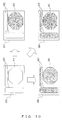
- the terminal device 930 illustrated in FIG. 8 or 9 may reproduce and display, on a display unit (not illustrated), only the moving image data recorded in the server device 400 or 800, or the moving image data recorded in the server device 400 or 800 and the patient data associated with the moving image data in accordance with a user's instruction. In this case, a reproduction display is performed as illustrated in FIG. 10 , for example.
- a user selects only a moving image display area 951, or the moving image display area 951 and a patient information display area 952 on an initial screen 950 of the reproduction display via an operating unit (not illustrated).
- an operating unit not illustrated
- a moving image video relating to the moving image data is reproduced and displayed in the moving image display area 951
- patient information relating to the patient data is reproduced and displayed in the patient information display area 952, as illustrated on a reproduction display screen 960.
- FIG. 10 an area in which a reproduction display is performed is illustrated in grey for convenience of explanation.
- a moving image video relating to the moving image data is reproduced and displayed in the moving image display area 951, but nothing is displayed in the patient information display area 952, as illustrated on a reproduction display screen 970.
- patient information that is reproduced and displayed in the patient information display area 952 and a background of the patient information display area 952 may be colored in the same color, as illustrated in a reproduction display screen 980 such that the patient information is not displayed consequently.
- the patient information display area 952 in which the reproduced and displayed patient information and the background are colored in the same color is illustrated with a dotted line, for convenience of explanation.
- a user can select whether the user displays only moving image data, or the moving image data and patient data associated with the moving image data, in accordance with the situation.
Landscapes
- Health & Medical Sciences (AREA)
- Life Sciences & Earth Sciences (AREA)
- Surgery (AREA)
- Engineering & Computer Science (AREA)
- General Health & Medical Sciences (AREA)
- Medical Informatics (AREA)
- Radiology & Medical Imaging (AREA)
- Public Health (AREA)
- Nuclear Medicine, Radiotherapy & Molecular Imaging (AREA)
- Heart & Thoracic Surgery (AREA)
- Physics & Mathematics (AREA)
- Biomedical Technology (AREA)
- Optics & Photonics (AREA)
- Biophysics (AREA)
- Molecular Biology (AREA)
- Animal Behavior & Ethology (AREA)
- Pathology (AREA)
- Veterinary Medicine (AREA)
- Signal Processing (AREA)
- Epidemiology (AREA)
- Primary Health Care (AREA)
- Studio Devices (AREA)
- Measuring And Recording Apparatus For Diagnosis (AREA)
- Endoscopes (AREA)
- Medical Treatment And Welfare Office Work (AREA)
Abstract
Description
- The present invention relates to an image photographing system including an image photographing device and a server device.
- Conventionally, an image photographing system having a configuration in which an image photographing device and a sever device are connected to each other via a communication network is used. The image photographing device is a device that performs processing such as photographing an image (a moving image or a still image), and the server device is a device that performs processing such as storing an image photographed by the image photographing device. In the image photographing system above, various types of data are transferred between the image photographing device and the server device.
- As an example of the image photographing system including the image photographing device and the server device, a system that includes an endoscope system including an endoscope and an endoscopic image recording device and a storing server, and the like are known (see, for example, Patent Document 1).
- Patent Document 1: Japanese Laid-Open Patent Publication No.
2011-98051 - In the image photographing system described above, as an example, when large-capacity moving image data is transferred from the image photographing device to the server device, a band is occupied in order to transfer the moving image data, and therefore it is likely that the transfer of the other data is delayed or that the other data fails to be transferred.
- In view of the situation above, an object of the present invention is to provide an image photographing system that can transfer data other than moving image data without delay, and that can reduce the time needed to transfer the moving image data as much as possible.
- In a first aspect of the present invention, an image photographing system is provided that includes an image photographing device connected to a first communication network, and a first server device connected to the first communication network, each of the image photographing device and the first server device including: a first logical port that is used to transfer moving image data; a second logical port that is used to transfer data other than the moving image data; a measuring unit that measures a data transfer amount of the second logical port; and a band control unit that controls transfer bands of the first logical port and the second logical port according to the data transfer amount measured by the measuring unit.
- In a second aspect of the present invention, the image photographing system in the first aspect is provided in which each of the image photographing device and the first server device further includes: a first physical port that is used to transfer the moving image data; and a second physical port that is used to transfer the data other than the moving image data, or the moving image data and the data other than the moving image data, the measuring unit measures the data transfer amount of the second logical port in the second physical port, and the band control unit controls the transfer bands of the first logical port and the second logical port in the second physical port according to the data transfer amount measured by the measuring unit.
- In a third aspect of the present invention, the image photographing system in the first or second aspect that further includes a second server device that is connected to a second communication network that is not connected to the first communication network is provided in which the image photographing device is also connected to the second communication network, and data that is transferred from the image photographing device via the first communication network to the first server device and that is recorded in the first server device is also transferred from the image photographing device via the second communication network to the second server device, and is also recorded in the second server device.
- In a fourth aspect of the present invention, the image photographing system in the first or second aspect is provided in which the image photographing device further includes a data recording unit, the data that is transferred from the image photographing device via the first communication network to the first server device and that is recorded in the first server device is also recorded in the data recording unit.
- In a fifth aspect of the present invention, the image photographing system in the third or fourth aspect is provided in which when transferring the data to the first server device, the image photographing device also transfers date data relating to the data to the first server device, and the first server device detects whether there is a possibility of falsification of the data on the basis of date at which the data transferred from the image photographing device is recorded and the date data relating to the data transferred from the image photographing device.
- In a sixth aspect of the present invention, the image photographing system in any one of the first to fifth aspects is provided in which the image photographing device further includes: an auxiliary power supply; and a power supply managing unit that manages power supply to respective units of the image photographing device, in the image photographing device, when power supply from a commercial power supply is interrupted during transfer of data, the power supply managing unit controls power supply to respective units needed to transfer the data to be performed from the auxiliary power supply such that the transfer of the data is continued, and controls power supply from the auxiliary power supply to be interrupted after the transfer of the data is completed.
- In a seventh aspect of the present invention, the image photographing system in any one of the first to fifth aspects is provided in which the image photographing device further includes a power supply managing unit that manages power supply to respective units of the image photographing device, in the image photographing device, when power supply from a commercial power supply is interrupted during transfer of data, the power supply managing unit controls power supply to respective units needed to transfer the data to be performed from a network device connected to the first communication network such that the transfer of the data is continued, and controls power supply from the network device to be interrupted after the transfer of the data is completed.
- In an eighth aspect of the present invention, the image photographing system in any one of the first to seventh aspects is provided in which the image photographing device further includes a moving image data recording unit that records the moving image data and personal data in association with each other, each of the image photographing device and the first server device that records the moving image data transferred from the image photographing device and the personal data associated with the moving image data displays only the moving image data, or the moving image data and the personal data associated with the moving image data.
- According to the present invention, an image photographing system can be provided that can transfer data other than moving image data without delay, and that can reduce the time needed to transfer the moving image data as much as possible.
-
-
FIG. 1 illustrates an exemplary configuration of a medical image photographing system according to a first embodiment. -
FIG. 2 illustrates an exemplary configuration of a medical image photographing device according to the first embodiment. -
FIG. 3 is a flowchart illustrating an example of processing relating to a transfer band control operation performed by the medical image photographing device according to the first embodiment. -
FIG. 4 illustrates an exemplary configuration of a medical image photographing system according to a second embodiment. -
FIG. 5 illustrates an exemplary configuration of a medical image photographing device according to the second embodiment. -
FIG. 6 is a flowchart illustrating an example of processing relating to a transfer band control operation performed by the medical image photographing device according to the second embodiment. -
FIG. 7 illustrates an exemplary configuration of a medical image photographing device according to a variation. -
FIG. 8 is a first diagram illustrating an exemplary configuration of a medical image photographing system according to a variation. -
FIG. 9 is a second diagram illustrating an exemplary configuration of a medical image photographing system according to a variation. -
FIG. 10 illustrates an example of a reproduction display according to a variation. - Embodiments of the present invention are described below with reference to the drawings.
- The embodiments below are described under the assumption that an image photographing system according to the present invention is applied to the medical field, and is used as a medical image photographing system. However, this is an example, and of course, the image photographing system according to the present invention may be applied to another field, and may be used as another type of image photographing system.
-
FIG. 1 illustrates an exemplary configuration of a medical image photographing system according to a first embodiment of the present invention. - As illustrated in
FIG. 1 , a medicalimage photographing system 100 according to this embodiment includes a medicalimage photographing device 200, acommunication network 300, and aserver device 400, and the medicalimage photographing system 100 has a configuration in which each of the medicalimage photographing device 200 and theserver device 400 is connected to thecommunication network 300. The medicalimage photographing device 200, thecommunication network 300, and theserver device 400 are examples of an image photographing device, a first communication network, and a first server device. - Each of the medical
image photographing device 200 and theserver device 400 includes a logical port A used to transfer moving image data and a logical port B used to transfer data other than the moving image data. The logical port A is also a logical port that is used by an application used to transfer moving image data. The logical port B is also a logical port that is used by an application used to transfer data other than the moving image data. The logical port A and the logical port B are examples of a first logical port and a second logical port. - The
communication network 300 has a network environment conforming to, for example, 100BASE-TX (an effective throughput is about 40 Mbps (Megabits per second)). -
FIG. 2 illustrates an exemplary configuration of the medicalimage photographing device 200. - As illustrated in
FIG. 2 , the medicalimage photographing device 200 includes anendoscope 210 and anendoscope video processor 220, and the medicalimage photographing device 200 has a configuration in which theendoscope 210 and theendoscope video processor 220 are connected to each other. - The
endoscope 210 outputs, to theendoscope video processor 220, a video signal obtained by capturing a subject image in accordance with a photographing instruction of a user (for example, a doctor). In the description below, it is assumed as an example that theendoscope 210 outputs, to theendoscope video processor 220, a video signal of a moving image obtained in accordance with a moving image photographing instruction of a user. - The
endoscope video processor 220 includes ascope interface unit 221, a movingimage encoding unit 222, arecording unit 223, a CPU (Central Processing Unit) 224, a characterdata generating unit 225, a powersupply managing unit 226, abattery 227, animage processing unit 228, and anetwork interface unit 229. Therecording unit 223 and thebattery 227 are examples of a moving image data recording unit and an auxiliary power supply. - The
scope interface unit 221 converts the video signal output from theendoscope 210 into image data, for example, by performing prescribed signal processing and A/D (Analog-to-Digital) conversion, and thescope interface unit 221 outputs the image data to the movingimage encoding unit 222. - The moving
image encoding unit 222 encodes the image data output from thescope interface unit 221 in a prescribed format (such as Motion JPEG (Motion Joint Photographic Experts Group), MPEG (Moving Picture Experts Group) 1, or MPEG2), and the movingimage encoding unit 222 outputs the encoded image data to therecording unit 223. - Examples of the
recording unit 223 include a CF (CompactFlash) card, and therecording unit 223 records the encoded image data (moving image data) that has been output from the movingimage encoding unit 222. Therecording unit 223 also records patient data (an example of personal data) or the like. The patient data is also character data, and the patient data is generated by the characterdata generating unit 225. Moving image data and corresponding patient data are recorded in therecording unit 223 in association with each other, as needed. - The
CPU 224 reads and executes a program stored in a memory (not illustrated) so as to control the entire operation of the medicalimage photographing device 200. - The character
data generating unit 225 generates various types of character data. As an example, the characterdata generating unit 225 generates patient data on the basis of data relating to a patient that is input via an operating unit (not illustrated), or data relating to a patient that is transmitted from an external device connected to thecommunication network 300. - The power
supply managing unit 226 manages power supply from an externalcommercial power supply 240 or thebattery 227 to respective units in the medical image photographing device 200 (for example, thescope interface unit 221, the movingimage encoding unit 222, therecording unit 223, theCPU 224, the characterdata generating unit 225, theimage processing unit 228, thenetwork interface unit 229, and the like) (see dotted-line arrows inFIG. 2 ). - The
image processing unit 228 performs various types of image processing. As an example, theimage processing unit 228 performs a process of synthesizing the moving image data recorded in therecording unit 223 and the associated patient data (character data) during photographing of a moving image. The moving image data that has been synthesized with the patient data by theimage processing unit 228, as described above, is displayed as a live video on a display unit (not illustrated). - The
network interface unit 229 is connected to thecommunication network 300, and performs data transfer, for example, from/to theserver device 400. In addition, thenetwork interface unit 229 includes an effectivethroughput measuring unit 230 and a transferband control unit 231. The effectivethroughput measuring unit 230 and the transferband control unit 231 are examples of a measuring unit and a band control unit. - The effective
throughput measuring unit 230 measures an effective throughput (a data transfer amount) per prescribed time period of the logical port B. In this embodiment, it is assumed that the prescribed time period is one minute, but is not limited to this. - The transfer
band control unit 231 controls transfer bands of the logical port A and the logical port B according to the effective throughput measured by the effectivethroughput measuring unit 230. - Similarly to the medical
image photographing device 200, theserver device 400 includes a CPU, and a network interface unit including an effective throughput measuring unit and a transfer band control unit, although these are not illustrated. -
FIG. 3 is a flowchart illustrating an example of processing relating to a transfer band control operation performed by the medicalimage photographing device 200. This processing is performed by theCPU 224 reading and executing a program stored in a memory (not illustrated). - As illustrated in
FIG. 3 , when theCPU 224 records and stores, in therecording unit 223, moving image data obtained in accordance with a moving image photographing instruction of a user (S101), theCPU 224 starts to transfer the moving image data to the server device 400 (S102). At this point in time, it is assumed that a transfer band of the logical port A used to transfer moving image data is set to 50 Mbps (this corresponds to 50% of the entirety of a transfer band) and that the remaining transfer band (50 Mbps) is set to be a transfer band of the logical port B used to transfer data other than the moving image data. - The
CPU 224 then determines whether transfer of moving image data has been completed (S103). When the determination result is No, the effectivethroughput measuring unit 230 measures an effective throughput per one minute of the data other than the moving image data, namely, an effective throughput per one minute in the logical port B, under the control of the CPU 224 (S104). - The
CPU 224 determines whether the effective throughput per one minute that has been measured in S104 is greater than or equal to 20 Mbps (this corresponds to 50% of an effective throughput of the communication network 300) (S105). When the determination result is Yes, the transferband control unit 231 sets a transfer band of the logical port A used to transfer moving image data to 20 Mbps (this corresponds to 20% of the entirety of a transfer band) under the control of the CPU 224 (S106). 20 Mbps is also a value that is estimated to make an effective throughput be about 8 Mbps. Consequently, the remaining transfer band (80 Mbps) is set to be a transfer band of the logical port B used to transfer data other than the moving image data. - When the determination result in S105 is No, the
CPU 224 determines whether the effective throughput per one minute that has been measured in S104 is greater than or equal to 5 Mbps (this corresponds to 12.5% of the effective throughput of the communication network 300) (S107). When the determination result is Yes, the transferband control unit 231 sets a transfer band of the logical port A used to transfer moving image data to 50 Mbps (this corresponds to 50% of the entirety of a transfer band) under the control of the CPU 224 (S108). 50 Mbps is also a value that is estimated to make an effective throughput be about 20 Mbps. Consequently, the remaining transfer band (50 Mbps) is set to be a transfer band of the logical port B used to transfer data other than the moving image data. - When the determination result in S107 is No, the transfer
band control unit 231 sets a transfer band of the logical port A used to transfer moving image data to 70 Mbps (this corresponds to 70% of the entirety of a transfer band) under the control of the CPU 224 (S109). 70 Mbps is also a value that is estimated to make an effective throughput be about 28 Mbps. Consequently, the remaining transfer band (30 Mbps) is set to be a transfer band of the logical port B used to transfer data other than the moving image data. - Following S106, S108, or S109, processing returns to S103.
- When the determination result in S103 is Yes, this processing is finished.
- A transfer band control operation performed by the
server device 400 is basically similar to the operation performed by the medicalimage photographing device 200, although this is not illustrated. Namely, in the transfer band control operation performed by theserver device 400, processing after moving image data starts to be transferred from the medicalimage photographing device 200 to theserver device 400 is similar to the processes of S103 to S109 illustrated inFIG. 3 . - As described above, in the medical
image photographing system 100 according to this embodiment, when an effective throughput per one minute of data other than moving image data increases during transfer of the moving image data from the medicalimage photographing device 200 to theserver device 400, a transfer band of the moving image data is set to be narrow, and a transfer band of the data other than the moving image data is set to be wide. When the effective throughput per one minute of the data other than the moving image data decreases during transfer of the moving image data from the medicalimage photographing device 200 to theserver device 400, the transfer band of the moving image data is set to be wide, and the transfer band of the data other than the moving image data is set to be narrow. Accordingly, in the medicalimage photographing system 100, the data other than the moving image data can be transferred without delay, and the time needed to transfer the moving image data can be reduced as much as possible. - In the transfer band control operation performed by the medical image photographing device 200 (see
FIG. 3 ), in a case in which power supply from the externalcommercial power supply 240 is interrupted, for example, because a user turns off a power switch (not illustrated) of the medicalimage photographing device 200 during transfer of moving image data, the following operation, for example, may be performed in the medicalimage photographing device 200. In this case, the powersupply managing unit 226 may control power supply to respective units needed to transfer the moving image data (for example, therecording unit 223, theCPU 224, thenetwork interface unit 229, and the like) to be performed from thebattery 227 such that transfer of the moving image data is continued, and the powersupply managing unit 226 may control power supply from thebattery 227 to be interrupted after transfer of the moving image data has been completed. More specifically, when the powersupply managing unit 226 detects interruption of power supply from the externalcommercial power supply 240 during transfer of moving image data, the powersupply managing unit 226 switches a power supply source from the externalcommercial power supply 240 to thebattery 227, and transmits a report (an auxiliary power supply switching report) to theCPU 224. Upon receipt of the report, theCPU 224 issues a request to interrupt power supply from the battery 227 (a power supply interruption request) to the powersupply managing unit 226, after transfer of the moving image data has been completed. Upon receipt of the request, the powersupply managing unit 226 interrupts the power supply from thebattery 227 in accordance with the request. When the powersupply managing unit 226 detects power supply from the externalcommercial power supply 240, the powersupply managing unit 226 performs control to switch a power supply source from thebattery 227 to the externalcommercial power supply 240 so as to supply power from the externalcommercial power supply 240 to the respective units in the medicalimage photographing device 200. The operation above allows transfer of moving image data to be continued without interruption, even when power supply from the externalcommercial power supply 240 is interrupted during transfer of the moving image data. The operation above is not limited to transfer of moving image data, and may be applied to transfer of data other than the moving image data -
FIG. 4 illustrates an exemplary configuration of a medical image photographing system according to a second embodiment of the present invention. - As illustrated in
FIG. 4 , a medicalimage photographing system 500 according to this embodiment includes a medicalimage photographing device 600, acommunication network 700, and aserver device 800, and the medicalimage photographing system 500 has a configuration in which each of the medicalimage photographing device 600 and theserver device 800 is connected to thecommunication network 700. The medicalimage photographing device 600, thecommunication network 700, and theserver device 800 are examples of an image photographing device, a first communication network, and a first server device. - Each of the medical
image photographing device 600 and theserver device 800 includes a logical port A used to transfer moving image data and a logical port B used to transfer data other than the moving image data. The logical port A is also a logical port that is used by an application used to transfer moving image data. The logical port B is also a logical port that is used by an application used to transfer data other than the moving image data. The logical port A and the logical port B are examples of a first logical port and a second logical port. - Each of the medical
image photographing device 600 and theserver device 800 also includes a physical port A that is used to transfer moving image data, and a physical port B that is used to transfer data other than the moving image data, or the moving image data and the data other than the moving image data. The physical port A and the physical port B are examples of a first physical port and a second physical port. - The
communication network 700 has a network environment in which each of a network environment between the physical port A of the medicalimage photographing device 600 and the physical port A of theserver device 800 and a network environment between the physical port B of the medicalimage photographing device 600 and the physical port B of theserver device 800 conforms, for example, to 100BASE-TX (an effective throughput is about 40 Mbps). Hereinafter, the network environment between the physical port A of the medicalimage photographing device 600 and the physical port A of theserver device 800 is also referred to as infrastructure to transfer a moving image. The network environment between the physical port B of the medicalimage photographing device 600 and the physical port B of theserver device 800 is also referred to as infrastructure to transfer other data. -
FIG. 5 illustrates an exemplary configuration of the medicalimage photographing device 600. - As illustrated in
FIG. 5 , a configuration of the medicalimage photographing device 600 is basically similar to the configuration of the medicalimage photographing device 200 illustrated inFIG. 2 , except that the medicalimage photographing device 600 includes twonetwork interface units - The
network interface unit 610 corresponds to the physical port A, and thenetwork interface unit 610 is connected to infrastructure to transfer a moving image, and transfers moving image data, for example, from/to theserver device 800. - The
network interface unit 620 corresponds to the physical port B, and thenetwork interface unit 620 is connected to infrastructure to transfer other data, and transfers data other than moving image data, or the moving image data and the data other than the moving image data, for example, from/to theserver device 800. Thenetwork interface unit 620 includes an effectivethroughput measuring unit 621 and a transferband control unit 622. The effectivethroughput measuring unit 621 and the transferband control unit 622 are examples of a measuring unit and a band control unit. - The effective
throughput measuring unit 621 measures an effective throughput per prescribed time period of the logical port B in the network interface unit 620 (the physical port B). Also in this embodiment, it is assumed that the prescribed time period is one minute, but is not limited to this. - The transfer
band control unit 622 controls transfer bands of the logical port A and the logical port B in the network interface unit 620 (the physical port B) in accordance with the effective throughput measured by the effectivethroughput measuring unit 621. - The other components are the same as the components illustrated in
FIG. 2 , and the description thereof is omitted. In the medicalimage photographing device 600 illustrated inFIG. 5 , the same components as the components illustrated inFIG. 2 are denoted by the same reference numerals. - Similarly to the medical
image photographing device 600, theserver device 800 includes a CPU, a network interface unit that corresponds to the physical port A, and a network interface unit that corresponds to the physical port B, although these are not illustrated. The network interface unit that corresponds to the physical port B includes an effective throughput measuring unit and a transfer band control unit, similarly to thenetwork interface unit 620. -
FIG. 6 is a flowchart illustrating an example of processing relating to a transfer band control operation performed by the medicalimage photographing device 600. This processing is performed by theCPU 224 reading and executing a program stored in a memory (not illustrated). - As illustrated in
FIG. 6 , when theCPU 224 records and stores, in therecording unit 223, moving image data obtained in accordance with a moving image photographing instruction of a user (S201), theCPU 224 starts to transfer the moving image data to the server device 800 (S202). At this point in time, it is assumed as an example that a transfer band of the logical port A in the physical port B is set to 20 Mbps (this corresponds to 20% of the entirety of a transfer band in the physical port B), and that the remaining transfer band (80 Mbps) in the physical port B is set to be a transfer band of the logical port B in the physical port B. - The
CPU 224 then determines whether transfer of moving image data has been completed (S203). When the determination result is No, the effectivethroughput measuring unit 621 measures an effective throughput per one minute of data other than the moving image data in thenetwork interface unit 620 connected to infrastructure to transfer other data, namely, an effective throughput per one minute of the logical port B in the physical port B, under the control of the CPU 224 (S204). - The
CPU 224 determines whether the effective throughput per one minute that has been measured in S204 is greater than or equal to 20 Mbps (this corresponds to 50% of an effective throughput of the infrastructure to transfer other data) (S205). When the determination result is Yes, the transferband control unit 622 sets a transfer band of moving image data in thenetwork interface unit 620, namely, a transfer band of the logical port A in the physical port B, to zero, under the control of theCPU 224. Consequently, the remaining transfer band in the physical port B, namely, the entirety of a transfer band (100 Mbps) of the physical port B, is set to be a transfer band of the logical port B in the physical port B. Accordingly, in this case, the infrastructure to transfer other data is not used to transfer a moving image. - When the determination result in S205 is No, the
CPU 224 determines whether the effective throughput per one minute that has been measured in S204 is greater than or equal to 5 Mbps (this corresponds to 12. 5% of the effective throughput of the infrastructure to transfer other data) (S207). When the determination result is Yes, the transferband control unit 622 sets a transfer band of moving image data in thenetwork interface unit 620, namely, a transfer band of the logical port A in the physical port B, to 20 Mbps (this corresponds to 20% of the entirety of a transfer band in the physical port B) under the control of the CPU 224 (S208). 20 Mbps is also a value that is estimated to make an effective throughput be about 8 Mbps. Consequently, the remaining transfer band (80 Mbps) in the physical port B is set to be a transfer band of the logical port B in the physical port B. - When the determination result in S207 is No, the transfer
band control unit 622 sets a transfer band of moving image data in thenetwork interface unit 620, namely, a transfer band of the logical port A in the physical port B, to 50 Mbps (this corresponds to 50% of the entirety of a transfer band in the physical port B) under the control of the CPU 224 (S209). 50 Mbps is also a value that is estimated to make an effective throughput be about 20 Mbps. Consequently, the remaining transfer band (50 Mbps) in the physical port B is set to be a transfer band of the logical port B in the physical port B. - Following S206, S208, or S209, processing returns to S203.
- When the determination result in S203 is Yes, and when a value that has been set to be the transfer band of the moving image data in the
network interface unit 620, namely, the transfer band of the logical port A in the physical port B, is not zero at this point in time, the value is set to zero (S210). Consequently, the remaining transfer band in the physical port B, namely, the entirety of a transfer band (100 Mbps) of the physical port B, is set to be a transfer band of the logical port B in the physical port B. Accordingly, in this case, in the infrastructure to transfer other data, a band used to transfer a moving image is released. - Following S210, this processing is finished.
- A transfer band control operation performed by the
server device 800 is basically similar to the operation performed by the medicalimage photographing device 600, although this is not illustrated. Namely, in the transfer band control operation performed by theserver device 800, processing after moving image data starts to be transferred from the medicalimage photographing device 600 to theserver device 800 is similar to the processes of S203 to S210 illustrated inFIG. 6 . - As described above, in the medical
image photographing system 500 according to this embodiment, moving image data is transferred from the medicalimage photographing device 600 to theserver device 800 by using infrastructure to transfer an moving image, or the infrastructure to transfer a moving image and infrastructure to transfer other data. During transfer of the moving image data, when an effective throughput per one minute of the data other than the moving image data increases in thenetwork interface unit 620 connected to the infrastructure to transfer other data, a transfer band of the moving image data is set to be narrow, and a transfer band of the data other than the moving image data is set to be wide. During transfer of the moving image data, when an effective throughput per one minute of the data other than the moving image data decreases in thenetwork interface unit 620, the transfer band of the moving image data is set to be wide, and the transfer band of the data other than the moving image data is set to be narrow. Accordingly, in the medicalimage photographing system 500, the data other than the moving image data can be transferred without delay, and the time needed to transfer the moving image data can be reduced as much as possible. - In the transfer band control operation performed by the medical image photographing device 600 (see
FIG. 6 ), when power supply from the externalcommercial power supply 240 is interrupted, for example, because a user turns off a power switch (not illustrated) of the medicalimage photographing device 600 during transfer of moving image data, the following operation, for example, may be performed by the medicalimage photographing device 600, similarly to in the first embodiment. In this case, the powersupply managing unit 226 may control power supply to respective units needed to transfer the moving image data (for example, therecording unit 223, theCPU 224, thenetwork interface units battery 227 such that the moving image data continued to be transferred, and the powersupply managing unit 226 may control power supply from thebattery 227 to be interrupted after transfer of the moving image data has been completed. The operation above allows the transfer of the moving image data to be continued without interruption, even when power supply from the externalcommercial power supply 240 is interrupted during the transfer of the moving image data. The operation above is not limited to the transfer of the moving image data, and may be applied to transfer of data other than the moving image data. - The first and second embodiments have been described above, but various variations to the respective embodiments can be made.
- As an example, in the medical
image photographing device 200 according to the first embodiment or the medicalimage photographing device 600 according to the second embodiment, when power supply from the externalcommercial power supply 240 is interrupted during transfer of data (for example, moving image data), power supply to respective units needed to transfer the data may be controlled to be performed from a network device connected to thecommunication network battery 227 is removed from the medicalimage photographing device 200 illustrated inFIG. 2 , and the medicalimage photographing device 200 illustrated inFIG. 2 is connected to a PoE (Power over Ethernet)compatible switching hub 301 that is a network device connected to thecommunication network 300, as illustrated inFIG. 7 . When power supply from the externalcommercial power supply 240 is interrupted during transfer of the data, the powersupply managing unit 226 controls power supply to respective units needed to transfer moving image data to be performed from the switchinghub 301 such that transfer of the data is continued, and the powersupply managing unit 226 controls power supply from the switchinghub 301 to be interrupted after transfer of the moving image data has been completed. In the variation above, it can be unnecessary to mount thebattery 227 onto the medicalimage photographing device - As another example, the medical
image photographing system 100 according to the first embodiment or the medicalimage photographing system 500 according to the second embodiment may have a configuration in which the medicalimage photographing device communication network 910 that is not connected to thecommunication network server device 920 is connected to thecommunication network 910, as illustrated inFIG. 8 . InFIG. 8 , connection between the medicalimage photographing device 600 and thecommunication network 700 and connection between theserver device 800 and thecommunication network 700 are illustrated as one communication line for convenience of explanation (the same applies toFIG. 9 described later). Thecommunication network 910 and theserver device 920 are examples of a second communication network and a second sever device. Data (for example, moving image data) that is transferred from the medicalimage photographing device hospital LAN server device server device image photographing device communication network 910 to theserver device 920, and may be recorded as original data in theserver device 920. The data that is transferred from the medicalimage photographing device server device server device hospital LAN server device 920 that is connected to thecommunication network 910 disconnected from the in-hospital LAN - As another example, the medical
image photographing system 100 according to the first embodiment or the medicalimage photographing system 500 according to the second embodiment may have a configuration in which the medicalimage photographing device data recording unit 940, as illustrated inFIG. 9 . Data (for example, moving image data) that is transferred from the medicalimage photographing device communication network server device server device data recording unit 940. Thedata recording unit 940 may be provided separately from therecording unit 223, or a portion of therecording unit 223 may be shared as thedata recording unit 940. The data that is transferred from the medicalimage photographing device server device server device hospital LAN data recording unit 940 can reduce a risk of data falsification due to security threat. - In the variations described using
FIGS. 8 and9 , as an example, when the medicalimage photographing device server device image photographing device server device server device image photographing device image photographing device server device - As another example, in the medical
image photographing system 100 according to the first embodiment, the medicalimage photographing system 500 according to the second embodiment, or a medical image photographing system according to the variation illustrated inFIG. 8 or9 , the medicalimage photographing device recording unit 223, or the moving image data recorded in therecording unit 223 and patient data associated with the moving image data on a display unit (not illustrated) in accordance with an instruction of a user (for example, a doctor). Theserver device image photographing device terminal device 930 illustrated inFIG. 8 or9 may reproduce and display, on a display unit (not illustrated), only the moving image data recorded in theserver device server device FIG. 10 , for example. First, a user selects only a movingimage display area 951, or the movingimage display area 951 and a patientinformation display area 952 on aninitial screen 950 of the reproduction display via an operating unit (not illustrated). When the user selects the movingimage display area 951 and the patientinformation display area 952, a moving image video relating to the moving image data is reproduced and displayed in the movingimage display area 951, and patient information relating to the patient data is reproduced and displayed in the patientinformation display area 952, as illustrated on areproduction display screen 960. InFIG. 10 , an area in which a reproduction display is performed is illustrated in grey for convenience of explanation. When a user selects only the movingimage display area 951 on theinitial screen 950, a moving image video relating to the moving image data is reproduced and displayed in the movingimage display area 951, but nothing is displayed in the patientinformation display area 952, as illustrated on areproduction display screen 970. In this case, as an example, patient information that is reproduced and displayed in the patientinformation display area 952 and a background of the patientinformation display area 952 may be colored in the same color, as illustrated in areproduction display screen 980 such that the patient information is not displayed consequently. On thereproduction display screen 980 inFIG. 10 , the patientinformation display area 952 in which the reproduced and displayed patient information and the background are colored in the same color is illustrated with a dotted line, for convenience of explanation. In this variation, a user can select whether the user displays only moving image data, or the moving image data and patient data associated with the moving image data, in accordance with the situation. - The embodiments described above give specific examples of the present invention in order to easily understand the invention, and the present invention is not limited to the embodiments described above. Various variations or modifications of the present invention can be made without departing from the spirit of the present invention specified in the claims.
-
- 100 Medical image photographing system
- 200 Medical image photographing device
- 210 Endoscope
- 220 Endoscope video processor
- 221 Scope interface unit
- 222 Moving image encoding unit
- 223 Recording unit
- 224 CPU
- 225 Character data generating unit
- 226 Power supply managing unit
- 227 Battery
- 228 Image processing unit
- 229 Network interface unit
- 230 Effective throughput measuring unit
- 231 Transfer band control unit
- 240 Commercial power supply
- 300 Communication network
- 301 Switching hub
- 400 Server device
- 500 Medical image photographing system
- 600 Medical image photographing device
- 610 Network interface unit
- 620 Network interface unit
- 621 Effective throughput measuring unit
- 622 Transfer band control unit
- 700 Communication network
- 800 Server device
- 910 Communication network
- 920 Server device
- 930 Terminal device
- 940 Data recording unit
- 950 Initial screen
- 951 Moving image display area
- 952 Patient information display area
- 960, 970, or 980 Reproduction display screen
Claims (8)
- An image photographing system including an image photographing device connected to a first communication network, and a first server device connected to the first communication network, each of the image photographing device and the first server device comprising:a first logical port that is used to transfer moving image data;a second logical port that is used to transfer data other than the moving image data;a measuring unit that measures a data transfer amount of the second logical port; anda band control unit that controls transfer bands of the first logical port and the second logical port according to the data transfer amount measured by the measuring unit.
- The image photographing system according to claim 1, each of the image photographing device and the first server device further comprising:a first physical port that is used to transfer the moving image data; anda second physical port that is used to transfer the data other than the moving image data, or the moving image data and the data other than the moving image data, whereinthe measuring unit measures the data transfer amount of the second logical port in the second physical port, andthe band control unit controls the transfer bands of the first logical port and the second logical port in the second physical port according to the data transfer amount measured by the measuring unit.
- The image photographing system according to claim 1 or 2, further comprising:a second server device that is connected to a second communication network that is not connected to the first communication network, whereinthe image photographing device is also connected to the second communication network, anddata that is transferred from the image photographing device via the first communication network to the first server device and that is recorded in the first server device is also transferred from the image photographing device via the second communication network to the second server device, and is also recorded in the second server device.
- The image photographing system according to claim 1 or 2, the image photographing device further comprising a data recording unit, wherein
the data that is transferred from the image photographing device via the first communication network to the first server device and that is recorded in the first server device is also recorded in the data recording unit. - The image photographing system according to claim 3 or 4, wherein
when transferring the data to the first server device, the image photographing device also transfers date data relating to the data to the first server device, and
the first server device detects whether there is a possibility of falsification of the data on the basis of date at which the data transferred from the image photographing device is recorded and the date data relating to the data transferred from the image photographing device. - The image photographing system according to any one of claims 1 to 5, the image photographing device further comprising:an auxiliary power supply; anda power supply managing unit that manages power supply to respective units of the image photographing device, whereinin the image photographing device, when power supply from a commercial power supply is interrupted during transfer of data, the power supply managing unit controls power supply to respective units needed to transfer the data to be performed from the auxiliary power supply such that the transfer of the data is continued, and controls power supply from the auxiliary power supply to be interrupted after the transfer of the data is completed.
- The image photographing system according to any one of claims 1 to 5, the image photographing device further comprising:a power supply managing unit that manages power supply to respective units of the image photographing device, whereinin the image photographing device, when power supply from a commercial power supply is interrupted during transfer of data, the power supply managing unit controls power supply to respective units needed to transfer the data to be performed from a network device connected to the first communication network such that the transfer of the data is continued, and controls power supply from the network device to be interrupted after the transfer of the data is completed.
- The image photographing system according to any one of claims 1 to 7, the image photographing device further comprising:a moving image data recording unit that records the moving image data and personal data in association with each other, whereineach of the image photographing device and the first server device that records the moving image data transferred from the image photographing device and the personal data associated with the moving image data displays only the moving image data, or the moving image data and the personal data associated with the moving image data.
Applications Claiming Priority (2)
| Application Number | Priority Date | Filing Date | Title |
|---|---|---|---|
| JP2013262012 | 2013-12-19 | ||
| PCT/JP2014/082243 WO2015093319A1 (en) | 2013-12-19 | 2014-12-05 | Image capture system |
Publications (2)
| Publication Number | Publication Date |
|---|---|
| EP3053515A1 true EP3053515A1 (en) | 2016-08-10 |
| EP3053515A4 EP3053515A4 (en) | 2017-09-27 |
Family
ID=53402668
Family Applications (1)
| Application Number | Title | Priority Date | Filing Date |
|---|---|---|---|
| EP14871202.9A Withdrawn EP3053515A4 (en) | 2013-12-19 | 2014-12-05 | Image capture system |
Country Status (5)
| Country | Link |
|---|---|
| US (1) | US9585542B2 (en) |
| EP (1) | EP3053515A4 (en) |
| JP (1) | JP5889489B2 (en) |
| CN (1) | CN105705082B (en) |
| WO (1) | WO2015093319A1 (en) |
Family Cites Families (18)
| Publication number | Priority date | Publication date | Assignee | Title |
|---|---|---|---|---|
| US5790177A (en) * | 1988-10-17 | 1998-08-04 | Kassatly; Samuel Anthony | Digital signal recording/reproduction apparatus and method |
| US6014694A (en) * | 1997-06-26 | 2000-01-11 | Citrix Systems, Inc. | System for adaptive video/audio transport over a network |
| JP3438857B2 (en) * | 1997-06-30 | 2003-08-18 | 株式会社エヌ・ティ・ティ・データ | Network communication quality control system and traffic management device |
| JP3884862B2 (en) * | 1998-04-30 | 2007-02-21 | キヤノン株式会社 | Data transfer device, data transfer device control method, and storage medium |
| AU2001260669A1 (en) * | 2000-05-31 | 2001-12-11 | Arkray, Inc. | Remote data control system and measuring data gathering method |
| JP2002034907A (en) | 2000-07-25 | 2002-02-05 | Olympus Optical Co Ltd | Endoscope image recording device, and endoscope image managing system |
| JP2002058017A (en) * | 2000-08-10 | 2002-02-22 | Nidek Co Ltd | Image-distributing device |
| CN101175326B (en) * | 2004-12-30 | 2010-07-07 | 华为技术有限公司 | Broadband access network for guaranteeing service QoS |
| JP2008284037A (en) * | 2007-05-15 | 2008-11-27 | Olympus Corp | Endoscope apparatus |
| EP2072133A1 (en) | 2007-12-20 | 2009-06-24 | Koninklijke Philips Electronics N.V. | Multi-compartment device with magnetic particles |
| JP2010046216A (en) * | 2008-08-20 | 2010-03-04 | Fujifilm Corp | Optical tomographic image obtaining apparatus and optical tomographic image obtaining method |
| JP5430272B2 (en) * | 2009-07-29 | 2014-02-26 | Hoya株式会社 | Medical image management system and image management server |
| US8780978B2 (en) * | 2009-11-04 | 2014-07-15 | Qualcomm Incorporated | Controlling video encoding using audio information |
| JP2011098051A (en) | 2009-11-05 | 2011-05-19 | Hoya Corp | Magnification endoscope |
| US9264664B2 (en) * | 2010-12-03 | 2016-02-16 | Intouch Technologies, Inc. | Systems and methods for dynamic bandwidth allocation |
| CN103458767B (en) | 2011-08-26 | 2015-09-16 | 奥林巴斯医疗株式会社 | medical apparatus system |
| US8881218B2 (en) * | 2011-09-09 | 2014-11-04 | Dell Products L.P. | Video transmission with enhanced area |
| JP2012038349A (en) * | 2011-11-11 | 2012-02-23 | Konica Minolta Medical & Graphic Inc | Diagnosis support system |
-
2014
- 2014-12-05 CN CN201480060756.3A patent/CN105705082B/en active Active
- 2014-12-05 EP EP14871202.9A patent/EP3053515A4/en not_active Withdrawn
- 2014-12-05 JP JP2015530208A patent/JP5889489B2/en active Active
- 2014-12-05 WO PCT/JP2014/082243 patent/WO2015093319A1/en not_active Ceased
-
2016
- 2016-05-02 US US15/143,714 patent/US9585542B2/en active Active
Also Published As
| Publication number | Publication date |
|---|---|
| CN105705082A (en) | 2016-06-22 |
| EP3053515A4 (en) | 2017-09-27 |
| JP5889489B2 (en) | 2016-03-22 |
| JPWO2015093319A1 (en) | 2017-03-16 |
| US20160242628A1 (en) | 2016-08-25 |
| CN105705082B (en) | 2019-05-28 |
| US9585542B2 (en) | 2017-03-07 |
| WO2015093319A1 (en) | 2015-06-25 |
Similar Documents
| Publication | Publication Date | Title |
|---|---|---|
| CN103716535B (en) | One kind switching screening-mode method and electronic equipment | |
| JP6472253B2 (en) | Image processing apparatus and control method thereof | |
| CN103209300A (en) | Imaging Apparatus, And Control Method | |
| US8525902B2 (en) | Image capturing apparatus and control method thereof, system, and program | |
| KR101692651B1 (en) | Method and apparatus for encapsulation of random access information for media transport and storage | |
| US20170206318A1 (en) | Medical system and medical device | |
| US9462182B2 (en) | Imaging apparatus and control method thereof | |
| TWI870648B (en) | Video frame codec architectures | |
| JP2011147034A (en) | Information processor, and method of controlling the same | |
| EP3053515A1 (en) | Image capture system | |
| JP6918628B2 (en) | Image processing equipment, communication equipment and their control methods, and programs | |
| US7616839B2 (en) | Image data transfer system, method of generating image data file, and computer program | |
| JP2016005103A (en) | Imaging apparatus and control method thereof | |
| US20140059027A1 (en) | Server device, client device, medical image processing system, and medical image processing method | |
| JP2014230239A (en) | Image processing system, imaging apparatus and program | |
| JP6719932B2 (en) | Information setting device, information management device, information generating device, control method thereof, and program | |
| US9967408B2 (en) | Information setting apparatus, information management apparatus, information generation apparatus, and method and program for controlling the same | |
| CN111462868A (en) | Medical image management method, device and storage medium | |
| JP2016174221A (en) | Communication device, communication system, and communication method | |
| TWI838035B (en) | Color gamut switching method and electronic device | |
| US20180336965A1 (en) | Medical communication system and medical device | |
| JP4677504B2 (en) | Imaging device | |
| JP5317772B2 (en) | Imaging apparatus, control method thereof, and program | |
| JP2006340150A (en) | Image list update method in digital camera system | |
| JP2010178360A (en) | Imaging device |
Legal Events
| Date | Code | Title | Description |
|---|---|---|---|
| PUAI | Public reference made under article 153(3) epc to a published international application that has entered the european phase |
Free format text: ORIGINAL CODE: 0009012 |
|
| 17P | Request for examination filed |
Effective date: 20160504 |
|
| AK | Designated contracting states |
Kind code of ref document: A1 Designated state(s): AL AT BE BG CH CY CZ DE DK EE ES FI FR GB GR HR HU IE IS IT LI LT LU LV MC MK MT NL NO PL PT RO RS SE SI SK SM TR |
|
| AX | Request for extension of the european patent |
Extension state: BA ME |
|
| RAP1 | Party data changed (applicant data changed or rights of an application transferred) |
Owner name: OLYMPUS CORPORATION |
|
| RAP1 | Party data changed (applicant data changed or rights of an application transferred) |
Owner name: OLYMPUS CORPORATION |
|
| RIN1 | Information on inventor provided before grant (corrected) |
Inventor name: OZAKI, TAKASHI Inventor name: KOIZUMI, YUGO Inventor name: SUZUKI, KEN Inventor name: SANO, DAISUKE |
|
| DAX | Request for extension of the european patent (deleted) | ||
| A4 | Supplementary search report drawn up and despatched |
Effective date: 20170830 |
|
| RIC1 | Information provided on ipc code assigned before grant |
Ipc: A61B 1/00 20060101AFI20170824BHEP Ipc: G06F 19/00 20110101ALI20170824BHEP |
|
| RIC1 | Information provided on ipc code assigned before grant |
Ipc: A61B 1/00 20060101AFI20171109BHEP Ipc: G06F 19/00 20110101ALI20171109BHEP |
|
| STAA | Information on the status of an ep patent application or granted ep patent |
Free format text: STATUS: REQUEST FOR EXAMINATION WAS MADE |
|
| STAA | Information on the status of an ep patent application or granted ep patent |
Free format text: STATUS: THE APPLICATION IS DEEMED TO BE WITHDRAWN |
|
| 18D | Application deemed to be withdrawn |
Effective date: 20180703 |