EP3052978B1 - Accessoire de lancement pour une détection de forme optique - Google Patents
Accessoire de lancement pour une détection de forme optique Download PDFInfo
- Publication number
- EP3052978B1 EP3052978B1 EP14777855.9A EP14777855A EP3052978B1 EP 3052978 B1 EP3052978 B1 EP 3052978B1 EP 14777855 A EP14777855 A EP 14777855A EP 3052978 B1 EP3052978 B1 EP 3052978B1
- Authority
- EP
- European Patent Office
- Prior art keywords
- launch
- fixture
- fiber
- launch fixture
- recited
- Prior art date
- Legal status (The legal status is an assumption and is not a legal conclusion. Google has not performed a legal analysis and makes no representation as to the accuracy of the status listed.)
- Active
Links
- 230000003287 optical effect Effects 0.000 title claims description 27
- 239000000835 fiber Substances 0.000 claims description 69
- 239000013307 optical fiber Substances 0.000 claims description 33
- 238000003384 imaging method Methods 0.000 claims description 16
- 238000000034 method Methods 0.000 claims description 15
- 230000008878 coupling Effects 0.000 claims description 11
- 238000010168 coupling process Methods 0.000 claims description 11
- 238000005859 coupling reaction Methods 0.000 claims description 11
- 230000010287 polarization Effects 0.000 claims description 6
- 230000007246 mechanism Effects 0.000 description 8
- 230000004888 barrier function Effects 0.000 description 6
- 230000006870 function Effects 0.000 description 6
- 230000000694 effects Effects 0.000 description 5
- 238000010586 diagram Methods 0.000 description 4
- 230000009466 transformation Effects 0.000 description 4
- 238000013461 design Methods 0.000 description 3
- 238000005259 measurement Methods 0.000 description 3
- 238000000844 transformation Methods 0.000 description 3
- 238000013459 approach Methods 0.000 description 2
- 230000008901 benefit Effects 0.000 description 2
- 238000005192 partition Methods 0.000 description 2
- 230000001681 protective effect Effects 0.000 description 2
- 239000000523 sample Substances 0.000 description 2
- 239000004065 semiconductor Substances 0.000 description 2
- 230000007704 transition Effects 0.000 description 2
- 238000013519 translation Methods 0.000 description 2
- 229910000831 Steel Inorganic materials 0.000 description 1
- 230000005540 biological transmission Effects 0.000 description 1
- 210000004204 blood vessel Anatomy 0.000 description 1
- 238000004891 communication Methods 0.000 description 1
- 150000001875 compounds Chemical class 0.000 description 1
- 238000004590 computer program Methods 0.000 description 1
- 230000001066 destructive effect Effects 0.000 description 1
- 230000009977 dual effect Effects 0.000 description 1
- 238000005516 engineering process Methods 0.000 description 1
- 210000001035 gastrointestinal tract Anatomy 0.000 description 1
- 230000036512 infertility Effects 0.000 description 1
- 230000003993 interaction Effects 0.000 description 1
- 210000004072 lung Anatomy 0.000 description 1
- 238000012423 maintenance Methods 0.000 description 1
- 238000012986 modification Methods 0.000 description 1
- 230000004048 modification Effects 0.000 description 1
- 210000000056 organ Anatomy 0.000 description 1
- 230000000399 orthopedic effect Effects 0.000 description 1
- 238000004806 packaging method and process Methods 0.000 description 1
- 230000000737 periodic effect Effects 0.000 description 1
- 230000002093 peripheral effect Effects 0.000 description 1
- 239000004033 plastic Substances 0.000 description 1
- 239000002985 plastic film Substances 0.000 description 1
- 229920006255 plastic film Polymers 0.000 description 1
- 230000008569 process Effects 0.000 description 1
- 239000011241 protective layer Substances 0.000 description 1
- 238000009877 rendering Methods 0.000 description 1
- 230000004044 response Effects 0.000 description 1
- 239000007787 solid Substances 0.000 description 1
- 229910001220 stainless steel Inorganic materials 0.000 description 1
- 239000010935 stainless steel Substances 0.000 description 1
- 230000003068 static effect Effects 0.000 description 1
- 239000010959 steel Substances 0.000 description 1
Images


Classifications
-
- G—PHYSICS
- G02—OPTICS
- G02B—OPTICAL ELEMENTS, SYSTEMS OR APPARATUS
- G02B6/00—Light guides; Structural details of arrangements comprising light guides and other optical elements, e.g. couplings
- G02B6/24—Coupling light guides
- G02B6/36—Mechanical coupling means
- G02B6/3616—Holders, macro size fixtures for mechanically holding or positioning fibres, e.g. on an optical bench
- G02B6/3624—Fibre head, e.g. fibre probe termination
-
- G—PHYSICS
- G01—MEASURING; TESTING
- G01B—MEASURING LENGTH, THICKNESS OR SIMILAR LINEAR DIMENSIONS; MEASURING ANGLES; MEASURING AREAS; MEASURING IRREGULARITIES OF SURFACES OR CONTOURS
- G01B11/00—Measuring arrangements characterised by the use of optical techniques
- G01B11/24—Measuring arrangements characterised by the use of optical techniques for measuring contours or curvatures
-
- G—PHYSICS
- G02—OPTICS
- G02B—OPTICAL ELEMENTS, SYSTEMS OR APPARATUS
- G02B6/00—Light guides; Structural details of arrangements comprising light guides and other optical elements, e.g. couplings
- G02B6/24—Coupling light guides
- G02B6/36—Mechanical coupling means
-
- A—HUMAN NECESSITIES
- A61—MEDICAL OR VETERINARY SCIENCE; HYGIENE
- A61B—DIAGNOSIS; SURGERY; IDENTIFICATION
- A61B17/00—Surgical instruments, devices or methods, e.g. tourniquets
- A61B2017/00477—Coupling
-
- A—HUMAN NECESSITIES
- A61—MEDICAL OR VETERINARY SCIENCE; HYGIENE
- A61B—DIAGNOSIS; SURGERY; IDENTIFICATION
- A61B34/00—Computer-aided surgery; Manipulators or robots specially adapted for use in surgery
- A61B34/20—Surgical navigation systems; Devices for tracking or guiding surgical instruments, e.g. for frameless stereotaxis
- A61B2034/2046—Tracking techniques
- A61B2034/2061—Tracking techniques using shape-sensors, e.g. fiber shape sensors with Bragg gratings
Definitions
- This disclosure relates to medical instruments and more particularly to shape sensing optical fibers in medical applications.
- Optical shape sensing is a technology that permits accurate three-dimensional (3D) reconstruction of a shape of a fiber along its entire length. Integrating the fiber into an OSS enabled instrument requires coupling the fiber to the instrument such that any movement of the device can be reconstructed with respect to a fixed frame of reference. Having a fixed or static launch region is needed since the fixed region provides a search template for a reconstruction algorithm to perform correlation and to match a reference to sample data. The reconstruction initializes after this fixed region. The fixed region also defines the frame of reference (0,0,0) for OSS and, in essence, the coordinate system in the shape sensing space.
- a launch fixture for optical shape sensing includes a first fixation device configured to receive and secure an optical fiber.
- a storage area is configured to receive and maintain the optical fiber within specified dimensions.
- a second fixation device is configured to receive and secure a flexible OSS enabled instrument.
- a launch region is configured to receive and maintain the optical fiber in aligning and coupling to a launch fixture base, which is configured to secure the launch fixture.
- An optical shape sensing (OSS) system includes a launch fixture base configured to be connected to a support structure, and a launch fixture configured to be secured on the launch fixture base by at least one feature for aligning and coupling the launch fixture base to the launch fixture.
- the launch fixture includes a first fixation device configured to receive and secure an optical fiber; a fiber storage area configured to receive and maintain the optical fiber within specified dimensions; a second fixation device configured to receive and secure a flexible OSS enabled instrument; and a launch region configured to receive and maintain the optical fiber in a known geometric configuration before entering the second fixation device.
- a method for optical shape sensing includes providing (502) a launch fixture having a first fixation device configured to receive and secure an optical fiber, a fiber storage area configured to receive and maintain the optical fiber within specified dimensions, a second fixation device configured to receive and secure a flexible OSS enabled instrument, a launch region configured to receive and maintain the optical fiber in a known geometric configuration before entering the second fixation device, and at least one feature for aligning and coupling to a launch fixture base, which is configured to secure the launch fixture; and sensing a shape of the optical fiber.
- a launch fixture and launch fixture base design provide for rapid attachment and detachment of one or more optical shape sensing (OSS) enabled flexible instrument(s) to a fixed reference in an operating theatre.
- the fixture can also be disposed in a transition zone between sterile and non-sterile regions in an operating theatre, allowing for the rapid exchange of OSS-enabled devices by personnel in the non-sterile region without breaking the sterile barrier.
- OSS optical shape sensing
- the launch fixture ensures that the geometric relationship between adjacent instrument frames of reference and the launch fixture base frame of reference are known, so that each instrument is automatically registered to the launch fixture base once connected. Given that the launch fixture base is registered to a patient or imaging frame of reference prior to a beginning of the procedure, this architecture permits each instrument to be rapidly deployed in a co-registered frame of reference. In addition, the overall footprint of the instruments in the operating theatre can be minimized through the use of vertical, horizontal, or angled stacking.
- each instrument could be attached to the operating table using a unique launch fixture base.
- a number of components attached to the table would increase accordingly. This would hinder clinician movement around the table and result in a cluttered operating field.
- the OSS fiber within each instrument will reconstruct the shape of the instrument with respect to a frame of reference located within that instruments' launch fixture, each instrument would need to be individually registered to the patient/imaging system frame of reference.
- the footprint of the instrument launch fixtures within the operating theatre is minimized, as well as the time spent registering devices.
- the launch fixture and launch fixture base permit rapid exchange of devices while maintaining a defined geometric relationship between frames of reference so that re-registration is not required.
- This fixed frame of reference is included within a launch fixture, which is coupled to a proximal end of the flexible instrument and includes design features which allow the fiber to be safely and securely coupled to the instrument.
- the present invention will be described in terms of medical instruments; however, the teachings of the present invention are much broader and are applicable to any fiber optic shape sensed instruments.
- the present principles are employed in tracking or analyzing complex biological or mechanical systems.
- the present principles are applicable to internal tracking procedures of biological systems, procedures in all areas of the body such as the lungs, gastro-intestinal tract, excretory organs, blood vessels, etc.
- the elements depicted in the FIGS. may be implemented in various combinations of hardware and software and provide functions which may be combined in a single element or multiple elements.
- processor or “controller” should not be construed to refer exclusively to hardware capable of executing software, and can implicitly include, without limitation, digital signal processor ("DSP") hardware, read-only memory (“ROM”) for storing software, random access memory (“RAM”), non-volatile storage, etc.
- DSP digital signal processor
- ROM read-only memory
- RAM random access memory
- non-volatile storage etc.
- embodiments of the present invention can take the form of a computer program product accessible from a computer-usable or computer-readable storage medium providing program code for use by or in connection with a computer or any instruction execution system.
- a computer-usable or computer readable storage medium can be any apparatus that may include, store, communicate, propagate, or transport the program for use by or in connection with the instruction execution system, apparatus, or device.
- the medium can be an electronic, magnetic, optical, electromagnetic, infrared, or semiconductor system (or apparatus or device) or a propagation medium.
- Examples of a computer-readable medium include a semiconductor or solid state memory, magnetic tape, a removable computer diskette, a random access memory (RAM), a read-only memory (ROM), a rigid magnetic disk and an optical disk.
- Current examples of optical disks include compact disk - read only memory (CD-ROM), compact disk - read/write (CD-R/W), Blu-RayTM and DVD
- System 100 may include a workstation or console 112 from which a procedure is supervised and/or managed.
- Workstation 112 preferably includes one or more processors 114 and memory 116 for storing programs and applications.
- Memory 116 may store an optical sensing module 115 configured to interpret optical feedback signals from a shape sensing device or system 104.
- Optical sensing module 115 is configured to use the optical signal feedback (and any other feedback, e.g., electromagnetic (EM) tracking) to reconstruct deformations, deflections and other changes associated with a medical device or instrument 102 and/or its surrounding region.
- the medical device 102 may include a catheter, a guidewire, a probe, an endoscope, a robot, an electrode, a filter device, a balloon device, or other medical component, etc.
- the shape sensing system 104 on device 102 includes one or more optical fibers 126 which are coupled to the device 102 in a set pattern or patterns.
- the optical fibers 126 connect to the workstation 112 through cabling 127.
- the cabling 127 may include fiber optics, electrical connections, other instrumentation, etc., as needed.
- Shape sensing system 104 with fiber optics may be based on fiber optic Bragg grating sensors.
- a fiber optic Bragg grating (FBG) is a short segment of optical fiber that reflects particular wavelengths of light and transmits all others. This is achieved by adding a periodic variation of the refractive index in the fiber core, which generates a wavelength-specific dielectric mirror.
- a fiber Bragg grating can therefore be used as an inline optical filter to block certain wavelengths, or as a wavelength-specific reflector.
- a fundamental principle behind the operation of a fiber Bragg grating is Fresnel reflection at each of the interfaces where the refractive index is changing. For some wavelengths, the reflected light of the various periods is in phase so that constructive interference exists for reflection and, consequently, destructive interference for transmission.
- the Bragg wavelength is sensitive to strain as well as to temperature. This means that Bragg gratings can be used as sensing elements in fiber optical sensors. In an FBG sensor, the measurand (e.g., strain) causes a shift in the Bragg wavelength.
- One advantage of this technique is that various sensor elements can be distributed over the length of a fiber. Incorporating three or more cores with various sensors (gauges) along the length of a fiber that is embedded in a structure permits a three dimensional form of such a structure to be precisely determined, typically with better than 1 mm accuracy.
- a multitude of FBG sensors can be located (e.g., 3 or more fiber sensing cores). From the strain measurement of each FBG, the curvature of the structure can be inferred at that position. From the multitude of measured positions, the total three-dimensional form is determined.
- workstation 112 includes an image generation module 148 configured to receive feedback from the shape sensing device 104 and display position/shape for the shape sensing device 104 within a volume 131.
- An image 134 of the shape sensing device 104 within the space or volume 131 can be displayed on a display device 118.
- Workstation 112 includes the display 118 for viewing internal images of a subject (patient) or volume 131 and may include the image 134 as an overlay or other rendering of shapes of the shape sensing device 104.
- Display 118 may also permit a user to interact with the workstation 112 and its components and functions, or any other element within the system 100. This is further facilitated by an interface 120 which may include a keyboard, mouse, a joystick, a haptic device, or any other peripheral or control to permit user feedback from and interaction with the workstation 112.
- a launch fixture 150 includes mechanical features 152 configured to ensure that the fiber 126 or the shape sensing device 104 can be coupled to the elongate instrument 102 such that the fiber measures changes in shape of the instrument with respect to a fixed frame of reference.
- Each OSS enabled instrument 102 employs a launch fixture (150) to define a fixed frame of reference which may be registered to a patient frame of reference 136, or imaging frame of reference 138, or both.
- a launch fixture base 160 is rigidly attached to a fixed feature or support structure 162 in the operating theatre (e.g., an operating table or similar structure) which allows for multiple launch fixtures 150 (and hence multiple OSS enabled instruments 102) to be attached and co-registered to the patient frame of reference 136, or imaging frame of reference 138, or both.
- the launch and coordinate systems of these fibers are known with respect to each other as well as the patient and imaging frames of reference 136, 138, thus allowing faster use when these devices are used in conjunction, such as, e.g., a guidewire and a catheter being used together.
- the launch base 160 and/or the launch fixture 150 may include features to monitor the use of the launch fixture 150 and devices 102.
- a scan mechanism 135 may be incorporated into the base 160 or fixture 150 (e.g., a radiofrequency scanner) that automatically detects which OSS enabled instrument 102 is being used.
- Mechanism 135 may monitor a number of times a same device is clipped in (to monitor or prevent) more than one-time use of the device 102.
- the mechanism 135 may include an indicator (e.g., a light, counter or color strip) that indicates an end of life (after say 1000 devices have been mounted) of the launch base 150 and alert the service engineer for maintenance.
- an indicator e.g., a light, counter or color strip
- Other configurations for mechanism 135 are also contemplated.
- a position of the launch fixture base 160 (and/or launch fixture 150) with respect to an imaging system 110 is tracked using an appropriate sensor 137 (position encoder, magnetic tracking, etc.). This provides easy registration to the imaging system 110.
- a sterile barrier 153 may be provided such that a proximal portion of device 150 (in region 154) is non-sterile and a distal portion of the device 150 (in region 154) is in the sterile region, which includes a mechanism (a barrier or sealed partition within the device 150) for not contaminating the sterile region 152 in an operating room.
- the launch fixture 150 allows use of OSS-enabled devices 104 without breaking the sterile barrier.
- the launch base 160 is also sterile and connects to the support 162 over a sterile drape 155. This combination also allows for the launch fixture 150 to be employed to enable the use of OSS instruments 102 without breaking the sterile barrier 153.
- a launch fixture 150 suitable for coupling an OSS fiber device 104 to a flexible instrument 102 in a controlled manner is illustratively shown.
- the launch fixture 150 includes a fixation point or device 172 to clamp the optical fiber 104 and its protective tubing, housing, or similar structure 173 in place into the fixture 150.
- a defined path 174 is formed to permit excess fiber to be included within the fixture 150 while not exceeding a specified minimum bend radius.
- This path 174 may also include features which allow for automatic alignment of the polarization of the OSS laser system to be performed while the instrument is connected to the OSS console. When a fiber undergoes a tight bend the index of refraction experienced by the light through that bend will vary depending on the orientation of the light.
- optical shape sensing measurements are commonly performed with multiple light polarizations.
- One technique to optimally select (or 'align') those polarization states is to use the measured optical response through a known feature, such as a bend.
- An example of such a feature is a defined path 174 with sufficient curvature to induce birefringence effects in the fiber.
- These birefringence effects provide unique features in the measured optical signal that can be used for automatic alignment of the system polarization. Ideally, this curvature will have a tight radius to amplify the birefringence effects and thus allow for a more unique feature upon which to perform alignment.
- This alignment feature can exist prior to a launch region 176 within the launch fixture 150.
- the launch region 176 permits the OSS fiber device 104 to be physically attached to the fixture 150 in a defined manner (e.g., straight or with a known geometry).
- the path prior to the launch region 176 may have features 177 which ensure the fiber enters the launch region 176 in a controlled manner (e.g., pegs, radiused features, etc.).
- a path 178 (which may be included in path 174) acts as a buffer, or service loop, to allow for curvature induced path length changes to be accommodated by the fiber repositioning within the fixture 150 while not exceeding a specified minimum bend radius.
- Such a service loop may take several different forms, e.g., the service buffer loop of path 178 may include a 90 degree, 360 degree bend, etc. instead of or in addition to the 180 degree bend depicted in FIG. 2 .
- a gap distance 171 of the path 178 provides slack for manipulating the fiber but protects the fiber from exceeding the minimum bend radius.
- a fixation point or device 180 clamps the flexible instrument 102 to the fixture 150 and surface curvatures/fillets 182 ensure that the transition between the fixture 150 and the flexible instrument 102 occurs without negatively effecting the strain measurement of the OSS fiber 104.
- Mechanical design features 184 allow the fixture 150 to be reproducibly connected to the launch fixture base 160 ( FIG. 1 ), or other launch fixtures in a known geometric manner. Screws, magnets, snap-fits, clips, pegs, or similar mechanisms can be employed to achieve this.
- Feature or features 184 with known geometry, curvature or shape may be employed for registering the device 102 to other OSS-enabled devices, the patient and the imaging frame of reference 136, 138.
- the feature(s) 184 may be employed for the dual purpose of attaching the fixture 150 to the launch base 160 and attaching fixtures 150 to each other.
- the feature(s) 184 may be directional shaped (e.g., square, triangle, etc.) to ensure that the base 160 and the fixtures 150 are properly aligned relative to one another.
- the launch fixture 150 is depicted in an open configuration in FIG. 2 .
- a lid (not shown) can be employed to cover the open launch fixture 150 or another launch fixture (not shown) may nest or be coupled to the launch fixture 150.
- the lid or additional launch fixture (150) may be screwed or otherwise connected into place to both clamp the components into place (on the base 160) and to protect the fiber from the environment by employing features 186.
- Feature 186 may include similar mechanism and described for features 184.
- An additional feature of the launch fixture 150 includes a defined path 179 for the fiber distal from the launch region 176 which can be used to correct for any rotation of the launch region during use.
- the fiber is clamped in place at the launch region 176; however, in some circumstances the fiber can 'rotate' within the clamp and thus any registrations can become inaccurate.
- the defined path 179 may include a curved path in two or three dimensions, e.g., a semi-circle, compound curves (e.g., sinusoid), an arc, a coiled shape, etc.
- the defined path 179 may be included distally to the launch region 176 within the launch fixture 150 or may be included as a detachable module 169 that connects to the launch fixture (as depicted in FIG. 2 ).
- the launch fixture base 160 includes features 190, such as holes, pegs, detents, protrusions, etc. configured to rigidly attach to a fixed frame of reference within the operating theatre (e.g., the operating table or the like).
- the launch fixture base 160 includes the ability to be reproducibly connected to one or more launch fixtures 150 with a known geometric relationship. This may include features 192, such as holes, pegs, detents, protrusions, etc. configured to permit easier connection and fixation of the launch fixture(s) 150 or a lid on the launch fixture(s) 150.
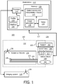
- three launch fixtures 150, 151 and 153 are connected to a launch fixture base 160 which is, in turn, connected to an operating table (not shown) via steel rods and support structure 163 and appropriate clamps, etc.
- the transformations between the frames of reference of the individual launch fixtures (and hence the flexible instruments 102 connected to the launch fixtures 150, 151, 153) and the launch fixture base 160 are known.
- different launch fixtures 150, 151, 153 can be connected to the launch fixture base 160 and used for imaged guided navigation without requiring a re-registration step.
- the known geometric relationship between each launch fixture 150, 151, 153 and the launch fixture base 160 can be used to minimize time spent registering each device to the patient/imaging system frame of reference.
- launch fixtures 150, 151, 153 can be rigidly attached to the launch fixture base 160 using threaded bolts 188.
- a lid 165 may be employed as well and secured together with fixtures150, 151, 153.
- additional launch fixtures 151, 153 can be attached to the initial launch fixture 150 with lid 165 using longer bolts.
- magnets, clips, snap fits or similar rapid attachment components may be employed instead of bolts to attach and detach the launch fixture(s) from each other and the launch fixture base 160.
- Quick connect or magnetic attachment mechanisms may be employed to make quick and secure but releasable connections between the base 160 and fixtures 150, 151, 153 and between fixtures 150, 151, 153.
- the geometric relationship between adjacent launch fixtures 150, 151, 153 (and hence their instrument frames of reference) and the launch fixture base 160 can be used to ensure that re-registration of multiple devices is not required as devices are exchanged during a procedure.
- by locating the fixtures 150, 151, 153 and base 160 at a single location clutter is reduced and an organized and efficient operating theater is maintained.
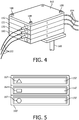
- launch fixtures 150' couple to a launch fixture base 160' independently (e.g., not stacked on each other).
- a launch fixture base 160' independently (e.g., not stacked on each other).
- Examples of such an embodiment include a rack-style base or similar architecture where the fixtures can be stacked horizontally, vertically or angled with respect to an operating table or other reference structure.
- connection features 163 may include different shapes for receiving different types of OSS enabled devices 102.
- a square, triangle, circle, etc. feature 163 may be employed to limit the type of OSS enabled device 102 connected to the launch fixture 150'.
- a guide wire may include a square connector
- a catheter may include a round connector
- an endoscope may include a triangular connector.
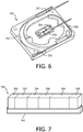
- a launch fixture 250 is shown capable of coupling two OSS fibers 104 to two flexible instruments 102 within a single fixture 250.
- An entrance point 254 for one fiber and an exit point 255 for one flexible instrument 102 are depicted.
- An entrance point 256 for one fiber and an exit point 257 for another flexible instrument 102 are also depicted.
- one instrument 102 may use a buffer, or service loop 252 and, the other instrument 102 may not employ the service loop 252.
- a service loop may be provided for both instruments in other embodiments.
- Other embodiments may employ a single fixture with a greater number of flexible instruments.
- a fiber path 258 may be employed for automatic alignment of light source polarization states, as described above.
- a modular launch fixture 350 is shown in accordance with one embodiment.
- the fixture 350 illustratively includes selected elements or features needed to couple an OSS fiber to a flexible instrument in a controlled manner.
- the launch fixture 350 in this particular embodiment adopts a modular approach to attaching each of a plurality of elements described above to a rail system or launch fixture base 362.
- This rail 362 can be attached to an operating table and then registered to the patient and/or imaging system frame of reference.
- the launch fixture 350 illustratively includes a launch region module 352, a buffer or service loop module 354, an excess fiber path module 356, a fiber boot clamp module 358, and a clamp module 360 for the flexible instrument 102.
- Other modules 364 may be included.
- the modules 352, 354, 356, 358, 362, 364 are individually separable from the launch fixture base 360 and adjacent modules.
- the modular embodiment of the launch fixture 350 may include multiple flexible instruments and/or stackable launch fixtures, each with one or more flexible instruments.
- the fibers in each module may include optical connectors so that modules can be easily changed out as needed.
- a protective layer 380 (e.g., a plastic film, sterile drape or the like) is disposed between the launch base 160 and the launch fixture 150, allowing a sterile device within a protected plastic 382 to clip on the non-sterile launch-base 160 while still having the packaging that maintains sterility. Others arrangements are also contemplated.
- the launch fixture base 160 can be multi-use, sterilizable and connect over a sterile drape 383.
- the launch fixture 150 can be connected to the sterile launch fixture base 160 thus allowing the OSS device to be used within the sterile field.
- a protective partition 386 e.g., a stainless steel wall
- sealed orifices 388 is disposed in the launch fixture 150, allowing a sterile device on a distal side (with instrument 102) and a non-sterile device on a proximal side (with fiber 104).
- Others arrangements are also contemplated.
- the launch fixture base 160 is coupled to a rail 402 or other structure such that the OSS enabled device 102 could be used for entering a body 131 at different locations, such as femoral access versus carotid access.
- the launch fixture base 160 could be repositioned at preset states or locations 404, 406 and lock into place by a clamp 408 or other securing device.
- the positions, orientations and transforms of the base 160 at these locations 404, 406 with respect to other locations would be known and thus, registering multiple OSS devices 102 would be straightforward and simple.
- the launch fixture 150 and/or launch fixture base 160 may be robotically actuated and manipulated to different positions with or without the rail 402 (the rail 402 may also be robotically positioned). Translation and rotation of the rail 402, the launch fixture 150 and/or launch fixture base 160 may be provided robotically for medical procedures (e.g., endovascular, endoluminal and/or orthopedic applications, etc.) or other applications. In another embodiment, translation along the rail 402 may be performed manually, and the transformations to the patient or imaging coordinate systems, or both, can be calculated by measuring the position along the rail 402 using a position sensing device (potentiometer, optical tracker, etc.). If a robot is employed, the fixtures 150 and base 160 may be registered to the robotic coordinate system.
- a position sensing device potentiometer, optical tracker, etc.
- a method for optical shape sensing includes providing a launch fixture for handling optical fiber in a controlled manner, in block 502.
- the launch fixture includes a first fixation device configured to receive and secure an optical fiber, a fiber storage area configured to receive and maintain the optical fiber within specified dimensions, a second fixation device configured to receive and secure a flexible OSS enabled instrument, a launch region configured to receive and maintain the optical fiber in a known geometric configuration before entering the second fixation device, and at least one feature for aligning and coupling to a launch fixture base, which is configured to secure the launch fixture.
- the launch fixture may include other features as well, e.g., a defined path which can be used to correct for rotation of the fiber launch region (as described above).
- the launch fixture is equipped with at least one OSS fiber, which is initially secured in the first fixation device, and at least one OSS enabled device, which is secured in the second fixation device.
- the OSS fiber is stowed in buffer or loop area configured to maintain minimum dimensions requirements to the fiber and to provide some slack for accommodating operational movement of the fiber without exceeding the requirements.
- the launch fixture is secured to a launch fixture base.
- the launch fixture base may be secured to an operating table, a rail system, robotic instrument, imaging system, etc. In one embodiment, the launch fixture base may be actuated to different position within an operating theater.
- other launch fixtures are stacked on the launch fixture and/or a lid is placed over the launch fixture.
- the launch fixture or fixtures and/or fixture base are registered to at least one of a patient frame of reference and an imaging frame of reference, although other references may be employed.
- a sterile barrier may be employed through the launch fixture(s), between the launch fixture and the launch fixture base or between modules of a modular launch fixture.
- the flexible OSS enabled instrument is employed to sense a shape of the optical fiber.
Landscapes
- Physics & Mathematics (AREA)
- General Physics & Mathematics (AREA)
- Optics & Photonics (AREA)
- Endoscopes (AREA)
- Light Guides In General And Applications Therefor (AREA)
- Length Measuring Devices By Optical Means (AREA)
- Measurement Of The Respiration, Hearing Ability, Form, And Blood Characteristics Of Living Organisms (AREA)
Claims (14)
- Accessoire de lancement (150) pour la détection de forme optique (OSS), comprenant :un premier dispositif de fixation (172) configuré pour recevoir et fixer une fibre optique ;une zone de stockage de fibre (174) configurée pour recevoir et maintenir la fibre optique dans les limites de dimensions spécifiées,un second dispositif de fixation (180) configuré pour recevoir et fixer un instrument souple compatible OSS ;une région de lancement (176) configurée pour recevoir et maintenir la fibre optique dans une configuration géométrique connue avant d'entrer le second dispositif de fixation (180) ;et ledit accessoire de lancement étant caractérisé en ce que la zone de stockage de fibre (174) inclut une région de boucle de service (178) pour stocker la fibre et acceptant le repositionnement de la fibre optique dans des limites de contraintes géométriques admissibles, etau moins une particularité (184) pour alignement et accouplement à une base d'accessoire de lancement, qui est configurée pour fixer l'accessoire de lancement.
- Accessoire selon la revendication 1, dans lequel l'accessoire inclut un côté ouvert pour charger la fibre optique en son sein et comprenant en outre un couvercle (165) pour fermer le côté ouvert.
- Accessoire selon la revendication 1, comprenant en outre une particularité de connexion (186) pour l'alignement et l'accouplement de l'accessoire de lancement à un ou plusieurs accessoires de lancement supplémentaires.
- Accessoire selon la revendication 1, comprenant en outre un accessoire de lancement modulaire (350) configuré pour permettre à des portions fonctionnelles de l'accessoire de lancement de pouvoir être séparément attachées et détachées à/de la base d'accessoire de lancement.
- Accessoire selon la revendication 1, comprenant en outre une particularité de forme géométrique (174, 177, 178) configurée pour maintenir une portion de la fibre optique dans une position connue pour permettre le calage de l'accessoire de lancement avec d'autres instruments.
- Accessoire selon la revendication 1, dans lequel l'accessoire (250) est configuré pour accepter une pluralité d'instruments compatibles OSS.
- Accessoire selon la revendication 1, dans lequel la zone de stockage de fibre (174) inclut un chemin défini pour la fibre, configuré pour optimiser l'alignement de polarisation d'une source de lumière.
- Accessoire selon la revendication 1, comprenant en outre un chemin de fibre défini (179) disposé de façon distale par rapport à la région de lancement pour fournir un contrôle de la rotation de fibre dans la région de lancement.
- Système de détection de forme optique (OSS), comprenant :une base d'accessoire de lancement (160) configurée pour être raccordée à une structure de support ; etl'accessoire de lancement (150) selon la revendication 1 à accoupler à la base d'accessoire de lancement.
- Système selon la revendication 9, dans lequel l'accessoire inclut un côté ouvert pour charger la fibre optique en son sein et comprenant en outre un couvercle (165) pour fermer le côté ouvert.
- Système selon la revendication 9, comprenant en outre une particularité de raccordement (184) pour l'alignement et l'accouplement de l'accessoire de lancement avec un ou plusieurs accessoires de lancement supplémentaires.
- Système selon la revendication 9, comprenant en outre un accessoire de lancement modulaire (350) configuré pour permettre à des portions fonctionnelles de l'accessoire de lancement de pouvoir être séparément attachées et détachées à et de la base d'accessoire de lancement.
- Procédé pour la détection de forme optique (OSS), comprenant :la fourniture (502) d'un accessoire de lancement ayant un premier dispositif de fixation configuré pour recevoir et fixer une fibre optique, une zone de stockage de fibre configurée pour recevoir et maintenir la fibre optique dans des limites de dimensions spécifiées, dans lequel la zone de stockage de fibre (174) inclut une région de boucle de service (178) pour stocker la fibre et accepter le repositionnement de la fibre optique dans des limites de contraintes géométriques admissibles, un second dispositif de fixation configuré pour recevoir et fixer un instrument souple compatible OSS, une région de lancement configurée pour recevoir et maintenir la fibre optique dans une configuration géométrique connue avant d'entrer le second dispositif de fixation, et au moins une particularité pour l'alignement et l'accouplement à une base d'accessoire de lancement, qui est configurée pour fixer l'accessoire de lancement ; etla détection (514) d'une forme de la fibre optique.
- Procédé selon la revendication 13, comprenant en outre : le calage (510) de l'accessoire de lancement sur au moins l'un d'un cadre de référence de patient et d'un cadre de référence d'imagerie.
Applications Claiming Priority (2)
| Application Number | Priority Date | Filing Date | Title |
|---|---|---|---|
| US201361884178P | 2013-09-30 | 2013-09-30 | |
| PCT/IB2014/064361 WO2015044814A1 (fr) | 2013-09-30 | 2014-09-10 | Accessoire de lancement pour une détection de forme optique |
Publications (2)
| Publication Number | Publication Date |
|---|---|
| EP3052978A1 EP3052978A1 (fr) | 2016-08-10 |
| EP3052978B1 true EP3052978B1 (fr) | 2018-11-28 |
Family
ID=51655792
Family Applications (1)
| Application Number | Title | Priority Date | Filing Date |
|---|---|---|---|
| EP14777855.9A Active EP3052978B1 (fr) | 2013-09-30 | 2014-09-10 | Accessoire de lancement pour une détection de forme optique |
Country Status (6)
| Country | Link |
|---|---|
| US (1) | US20160223753A1 (fr) |
| EP (1) | EP3052978B1 (fr) |
| JP (1) | JP6517820B2 (fr) |
| CN (1) | CN105593731B (fr) |
| RU (1) | RU2663690C2 (fr) |
| WO (1) | WO2015044814A1 (fr) |
Families Citing this family (8)
| Publication number | Priority date | Publication date | Assignee | Title |
|---|---|---|---|---|
| US11141222B2 (en) | 2015-06-12 | 2021-10-12 | Koninklijke Philips N.V. | Universal fiber-optical realshape insert |
| CN108135531B (zh) * | 2015-10-02 | 2021-06-29 | 皇家飞利浦有限公司 | 用于利用光学形状感测的导丝来放置设备的衬套 |
| JP7171432B2 (ja) * | 2015-10-02 | 2022-11-15 | コーニンクレッカ フィリップス エヌ ヴェ | 光学形状感知されるガイドワイヤによるデバイスナビゲーションのためのハブ |
| EP3397183B1 (fr) | 2015-12-29 | 2022-10-19 | Koninklijke Philips N.V. | Système d'enregistrement pour navigation médicale et son procédé de fonctionnement |
| CN109475725B (zh) * | 2016-07-15 | 2022-07-08 | 皇家飞利浦有限公司 | 包括形状感测光纤的球囊导管 |
| EP3461388A1 (fr) * | 2017-09-28 | 2019-04-03 | Koninklijke Philips N.V. | Dispositif et procédé de connexion optique |
| US11896330B2 (en) * | 2019-08-15 | 2024-02-13 | Auris Health, Inc. | Robotic medical system having multiple medical instruments |
| CN112171606B (zh) * | 2020-09-22 | 2022-08-23 | 哈尔滨工业大学 | 一种机器人关节的fbg光纤集成辅助钳位平台及装配方法 |
Citations (1)
| Publication number | Priority date | Publication date | Assignee | Title |
|---|---|---|---|---|
| US20120224823A1 (en) * | 2011-03-04 | 2012-09-06 | Terry Dean Cox | Fiber optic adapter mount |
Family Cites Families (12)
| Publication number | Priority date | Publication date | Assignee | Title |
|---|---|---|---|---|
| US4325607A (en) * | 1979-03-26 | 1982-04-20 | Gte Laboratories Incorporated | Apparatus for connecting optical fibers |
| US4373779A (en) * | 1980-11-07 | 1983-02-15 | Litton Systems, Inc. | Single channel optical slip ring |
| US6905252B2 (en) * | 2002-08-21 | 2005-06-14 | Finisar Corporation | Optical interconnection sub-assembly |
| US7720322B2 (en) * | 2008-06-30 | 2010-05-18 | Intuitive Surgical, Inc. | Fiber optic shape sensor |
| JP5230711B2 (ja) * | 2009-10-19 | 2013-07-10 | 鴻海精密工業股▲ふん▼有限公司 | コネクタ |
| JP5506337B2 (ja) * | 2009-11-16 | 2014-05-28 | オリンパス株式会社 | 三次元形状検出装置 |
| US10456594B2 (en) * | 2009-12-28 | 2019-10-29 | Koninklijke Philips N.V. | Method and apparatus for brachytherapy featuring tracking via shape-sensing |
| JP5455688B2 (ja) * | 2010-02-02 | 2014-03-26 | Hoya株式会社 | 内視鏡 |
| US9285246B2 (en) * | 2010-02-12 | 2016-03-15 | Intuitive Surgical Operations, Inc. | Method and system for absolute three-dimensional measurements using a twist-insensitive shape sensor |
| US10820830B2 (en) * | 2011-01-28 | 2020-11-03 | Koninklijke Philips N.V. | Reference markers for launch point identification in optical shape sensing systems |
| US20130030363A1 (en) * | 2011-07-29 | 2013-01-31 | Hansen Medical, Inc. | Systems and methods utilizing shape sensing fibers |
| US9405085B2 (en) * | 2011-10-26 | 2016-08-02 | Koninklijke Philips N.V. | Smart tool holder for an optical shape-sensing fiber |
-
2014
- 2014-09-10 CN CN201480053986.7A patent/CN105593731B/zh active Active
- 2014-09-10 JP JP2016545072A patent/JP6517820B2/ja active Active
- 2014-09-10 US US15/021,047 patent/US20160223753A1/en not_active Abandoned
- 2014-09-10 EP EP14777855.9A patent/EP3052978B1/fr active Active
- 2014-09-10 WO PCT/IB2014/064361 patent/WO2015044814A1/fr active Application Filing
- 2014-09-10 RU RU2016116765A patent/RU2663690C2/ru active
Patent Citations (1)
| Publication number | Priority date | Publication date | Assignee | Title |
|---|---|---|---|---|
| US20120224823A1 (en) * | 2011-03-04 | 2012-09-06 | Terry Dean Cox | Fiber optic adapter mount |
Also Published As
| Publication number | Publication date |
|---|---|
| JP6517820B2 (ja) | 2019-05-22 |
| CN105593731B (zh) | 2017-12-05 |
| WO2015044814A1 (fr) | 2015-04-02 |
| RU2663690C2 (ru) | 2018-08-08 |
| RU2016116765A3 (fr) | 2018-06-01 |
| JP2016540992A (ja) | 2016-12-28 |
| EP3052978A1 (fr) | 2016-08-10 |
| RU2016116765A (ru) | 2017-11-13 |
| CN105593731A (zh) | 2016-05-18 |
| US20160223753A1 (en) | 2016-08-04 |
Similar Documents
| Publication | Publication Date | Title |
|---|---|---|
| EP3052978B1 (fr) | Accessoire de lancement pour une détection de forme optique | |
| US10639007B2 (en) | Automatic tracking and registration of ultrasound probe using optical shape sensing without tip fixation | |
| US9693707B2 (en) | Optical shape sensing fiber for tip and shape characterization of medical instruments | |
| US20220378519A1 (en) | Docking device for optical shape sensing launch fixtures | |
| US11547489B2 (en) | Shape sensing of multiple over-the-wire devices | |
| EP2866642B1 (fr) | Navigation guide par capteur optique à fibre pour visualisation et contrôle vasculaire | |
| US20160213432A1 (en) | Hub design and methods for optical shape sensing registration | |
| US20160331469A1 (en) | Virtual image with optical shape sensing device perspective | |
| EP2877096B1 (fr) | Cartographie précise et rapide de points à partir d'images d'ultrasons pour systèmes de suivi | |
| JP2017537698A5 (fr) | ||
| US20170265946A1 (en) | Shape sensed robotic ultrasound for minimally invasive interventions | |
| EP2667773A1 (fr) | Modèles d'étalonnage pour détection de formes optiques durant l'utilisation clinique | |
| EP2879586B1 (fr) | Quantification de déviation de sonde pour identification de cathéter améliorée | |
| US10357323B2 (en) | System and method for minimizing twist for optical shape sensing enabled instruments |
Legal Events
| Date | Code | Title | Description |
|---|---|---|---|
| PUAI | Public reference made under article 153(3) epc to a published international application that has entered the european phase |
Free format text: ORIGINAL CODE: 0009012 |
|
| 17P | Request for examination filed |
Effective date: 20160502 |
|
| AK | Designated contracting states |
Kind code of ref document: A1 Designated state(s): AL AT BE BG CH CY CZ DE DK EE ES FI FR GB GR HR HU IE IS IT LI LT LU LV MC MK MT NL NO PL PT RO RS SE SI SK SM TR |
|
| AX | Request for extension of the european patent |
Extension state: BA ME |
|
| DAX | Request for extension of the european patent (deleted) | ||
| STAA | Information on the status of an ep patent application or granted ep patent |
Free format text: STATUS: EXAMINATION IS IN PROGRESS |
|
| 17Q | First examination report despatched |
Effective date: 20170508 |
|
| GRAP | Despatch of communication of intention to grant a patent |
Free format text: ORIGINAL CODE: EPIDOSNIGR1 |
|
| STAA | Information on the status of an ep patent application or granted ep patent |
Free format text: STATUS: GRANT OF PATENT IS INTENDED |
|
| INTG | Intention to grant announced |
Effective date: 20180625 |
|
| GRAS | Grant fee paid |
Free format text: ORIGINAL CODE: EPIDOSNIGR3 |
|
| GRAA | (expected) grant |
Free format text: ORIGINAL CODE: 0009210 |
|
| STAA | Information on the status of an ep patent application or granted ep patent |
Free format text: STATUS: THE PATENT HAS BEEN GRANTED |
|
| AK | Designated contracting states |
Kind code of ref document: B1 Designated state(s): AL AT BE BG CH CY CZ DE DK EE ES FI FR GB GR HR HU IE IS IT LI LT LU LV MC MK MT NL NO PL PT RO RS SE SI SK SM TR |
|
| REG | Reference to a national code |
Ref country code: CH Ref legal event code: EP |
|
| REG | Reference to a national code |
Ref country code: AT Ref legal event code: REF Ref document number: 1070897 Country of ref document: AT Kind code of ref document: T Effective date: 20181215 |
|
| REG | Reference to a national code |
Ref country code: DE Ref legal event code: R096 Ref document number: 602014037016 Country of ref document: DE |
|
| REG | Reference to a national code |
Ref country code: IE Ref legal event code: FG4D |
|
| REG | Reference to a national code |
Ref country code: NL Ref legal event code: MP Effective date: 20181128 |
|
| REG | Reference to a national code |
Ref country code: LT Ref legal event code: MG4D |
|
| REG | Reference to a national code |
Ref country code: AT Ref legal event code: MK05 Ref document number: 1070897 Country of ref document: AT Kind code of ref document: T Effective date: 20181128 |
|
| PG25 | Lapsed in a contracting state [announced via postgrant information from national office to epo] |
Ref country code: LT Free format text: LAPSE BECAUSE OF FAILURE TO SUBMIT A TRANSLATION OF THE DESCRIPTION OR TO PAY THE FEE WITHIN THE PRESCRIBED TIME-LIMIT Effective date: 20181128 Ref country code: NO Free format text: LAPSE BECAUSE OF FAILURE TO SUBMIT A TRANSLATION OF THE DESCRIPTION OR TO PAY THE FEE WITHIN THE PRESCRIBED TIME-LIMIT Effective date: 20190228 Ref country code: HR Free format text: LAPSE BECAUSE OF FAILURE TO SUBMIT A TRANSLATION OF THE DESCRIPTION OR TO PAY THE FEE WITHIN THE PRESCRIBED TIME-LIMIT Effective date: 20181128 Ref country code: AT Free format text: LAPSE BECAUSE OF FAILURE TO SUBMIT A TRANSLATION OF THE DESCRIPTION OR TO PAY THE FEE WITHIN THE PRESCRIBED TIME-LIMIT Effective date: 20181128 Ref country code: LV Free format text: LAPSE BECAUSE OF FAILURE TO SUBMIT A TRANSLATION OF THE DESCRIPTION OR TO PAY THE FEE WITHIN THE PRESCRIBED TIME-LIMIT Effective date: 20181128 Ref country code: IS Free format text: LAPSE BECAUSE OF FAILURE TO SUBMIT A TRANSLATION OF THE DESCRIPTION OR TO PAY THE FEE WITHIN THE PRESCRIBED TIME-LIMIT Effective date: 20190328 Ref country code: BG Free format text: LAPSE BECAUSE OF FAILURE TO SUBMIT A TRANSLATION OF THE DESCRIPTION OR TO PAY THE FEE WITHIN THE PRESCRIBED TIME-LIMIT Effective date: 20190228 Ref country code: ES Free format text: LAPSE BECAUSE OF FAILURE TO SUBMIT A TRANSLATION OF THE DESCRIPTION OR TO PAY THE FEE WITHIN THE PRESCRIBED TIME-LIMIT Effective date: 20181128 Ref country code: FI Free format text: LAPSE BECAUSE OF FAILURE TO SUBMIT A TRANSLATION OF THE DESCRIPTION OR TO PAY THE FEE WITHIN THE PRESCRIBED TIME-LIMIT Effective date: 20181128 |
|
| PG25 | Lapsed in a contracting state [announced via postgrant information from national office to epo] |
Ref country code: GR Free format text: LAPSE BECAUSE OF FAILURE TO SUBMIT A TRANSLATION OF THE DESCRIPTION OR TO PAY THE FEE WITHIN THE PRESCRIBED TIME-LIMIT Effective date: 20190301 Ref country code: RS Free format text: LAPSE BECAUSE OF FAILURE TO SUBMIT A TRANSLATION OF THE DESCRIPTION OR TO PAY THE FEE WITHIN THE PRESCRIBED TIME-LIMIT Effective date: 20181128 Ref country code: AL Free format text: LAPSE BECAUSE OF FAILURE TO SUBMIT A TRANSLATION OF THE DESCRIPTION OR TO PAY THE FEE WITHIN THE PRESCRIBED TIME-LIMIT Effective date: 20181128 Ref country code: SE Free format text: LAPSE BECAUSE OF FAILURE TO SUBMIT A TRANSLATION OF THE DESCRIPTION OR TO PAY THE FEE WITHIN THE PRESCRIBED TIME-LIMIT Effective date: 20181128 Ref country code: PT Free format text: LAPSE BECAUSE OF FAILURE TO SUBMIT A TRANSLATION OF THE DESCRIPTION OR TO PAY THE FEE WITHIN THE PRESCRIBED TIME-LIMIT Effective date: 20190328 |
|
| PG25 | Lapsed in a contracting state [announced via postgrant information from national office to epo] |
Ref country code: NL Free format text: LAPSE BECAUSE OF FAILURE TO SUBMIT A TRANSLATION OF THE DESCRIPTION OR TO PAY THE FEE WITHIN THE PRESCRIBED TIME-LIMIT Effective date: 20181128 |
|
| PG25 | Lapsed in a contracting state [announced via postgrant information from national office to epo] |
Ref country code: PL Free format text: LAPSE BECAUSE OF FAILURE TO SUBMIT A TRANSLATION OF THE DESCRIPTION OR TO PAY THE FEE WITHIN THE PRESCRIBED TIME-LIMIT Effective date: 20181128 Ref country code: IT Free format text: LAPSE BECAUSE OF FAILURE TO SUBMIT A TRANSLATION OF THE DESCRIPTION OR TO PAY THE FEE WITHIN THE PRESCRIBED TIME-LIMIT Effective date: 20181128 Ref country code: DK Free format text: LAPSE BECAUSE OF FAILURE TO SUBMIT A TRANSLATION OF THE DESCRIPTION OR TO PAY THE FEE WITHIN THE PRESCRIBED TIME-LIMIT Effective date: 20181128 Ref country code: CZ Free format text: LAPSE BECAUSE OF FAILURE TO SUBMIT A TRANSLATION OF THE DESCRIPTION OR TO PAY THE FEE WITHIN THE PRESCRIBED TIME-LIMIT Effective date: 20181128 |
|
| REG | Reference to a national code |
Ref country code: DE Ref legal event code: R097 Ref document number: 602014037016 Country of ref document: DE |
|
| PG25 | Lapsed in a contracting state [announced via postgrant information from national office to epo] |
Ref country code: SM Free format text: LAPSE BECAUSE OF FAILURE TO SUBMIT A TRANSLATION OF THE DESCRIPTION OR TO PAY THE FEE WITHIN THE PRESCRIBED TIME-LIMIT Effective date: 20181128 Ref country code: RO Free format text: LAPSE BECAUSE OF FAILURE TO SUBMIT A TRANSLATION OF THE DESCRIPTION OR TO PAY THE FEE WITHIN THE PRESCRIBED TIME-LIMIT Effective date: 20181128 Ref country code: SK Free format text: LAPSE BECAUSE OF FAILURE TO SUBMIT A TRANSLATION OF THE DESCRIPTION OR TO PAY THE FEE WITHIN THE PRESCRIBED TIME-LIMIT Effective date: 20181128 Ref country code: EE Free format text: LAPSE BECAUSE OF FAILURE TO SUBMIT A TRANSLATION OF THE DESCRIPTION OR TO PAY THE FEE WITHIN THE PRESCRIBED TIME-LIMIT Effective date: 20181128 |
|
| PLBE | No opposition filed within time limit |
Free format text: ORIGINAL CODE: 0009261 |
|
| STAA | Information on the status of an ep patent application or granted ep patent |
Free format text: STATUS: NO OPPOSITION FILED WITHIN TIME LIMIT |
|
| PG25 | Lapsed in a contracting state [announced via postgrant information from national office to epo] |
Ref country code: SI Free format text: LAPSE BECAUSE OF FAILURE TO SUBMIT A TRANSLATION OF THE DESCRIPTION OR TO PAY THE FEE WITHIN THE PRESCRIBED TIME-LIMIT Effective date: 20181128 |
|
| 26N | No opposition filed |
Effective date: 20190829 |
|
| PG25 | Lapsed in a contracting state [announced via postgrant information from national office to epo] |
Ref country code: TR Free format text: LAPSE BECAUSE OF FAILURE TO SUBMIT A TRANSLATION OF THE DESCRIPTION OR TO PAY THE FEE WITHIN THE PRESCRIBED TIME-LIMIT Effective date: 20181128 |
|
| PG25 | Lapsed in a contracting state [announced via postgrant information from national office to epo] |
Ref country code: MC Free format text: LAPSE BECAUSE OF FAILURE TO SUBMIT A TRANSLATION OF THE DESCRIPTION OR TO PAY THE FEE WITHIN THE PRESCRIBED TIME-LIMIT Effective date: 20181128 |
|
| REG | Reference to a national code |
Ref country code: CH Ref legal event code: PL |
|
| PG25 | Lapsed in a contracting state [announced via postgrant information from national office to epo] |
Ref country code: CH Free format text: LAPSE BECAUSE OF NON-PAYMENT OF DUE FEES Effective date: 20190930 Ref country code: LU Free format text: LAPSE BECAUSE OF NON-PAYMENT OF DUE FEES Effective date: 20190910 Ref country code: LI Free format text: LAPSE BECAUSE OF NON-PAYMENT OF DUE FEES Effective date: 20190930 Ref country code: IE Free format text: LAPSE BECAUSE OF NON-PAYMENT OF DUE FEES Effective date: 20190910 |
|
| REG | Reference to a national code |
Ref country code: BE Ref legal event code: MM Effective date: 20190930 |
|
| PG25 | Lapsed in a contracting state [announced via postgrant information from national office to epo] |
Ref country code: BE Free format text: LAPSE BECAUSE OF NON-PAYMENT OF DUE FEES Effective date: 20190930 |
|
| PG25 | Lapsed in a contracting state [announced via postgrant information from national office to epo] |
Ref country code: CY Free format text: LAPSE BECAUSE OF FAILURE TO SUBMIT A TRANSLATION OF THE DESCRIPTION OR TO PAY THE FEE WITHIN THE PRESCRIBED TIME-LIMIT Effective date: 20181128 |
|
| PG25 | Lapsed in a contracting state [announced via postgrant information from national office to epo] |
Ref country code: MT Free format text: LAPSE BECAUSE OF FAILURE TO SUBMIT A TRANSLATION OF THE DESCRIPTION OR TO PAY THE FEE WITHIN THE PRESCRIBED TIME-LIMIT Effective date: 20181128 Ref country code: HU Free format text: LAPSE BECAUSE OF FAILURE TO SUBMIT A TRANSLATION OF THE DESCRIPTION OR TO PAY THE FEE WITHIN THE PRESCRIBED TIME-LIMIT; INVALID AB INITIO Effective date: 20140910 |
|
| PG25 | Lapsed in a contracting state [announced via postgrant information from national office to epo] |
Ref country code: MK Free format text: LAPSE BECAUSE OF FAILURE TO SUBMIT A TRANSLATION OF THE DESCRIPTION OR TO PAY THE FEE WITHIN THE PRESCRIBED TIME-LIMIT Effective date: 20181128 |
|
| PGFP | Annual fee paid to national office [announced via postgrant information from national office to epo] |
Ref country code: GB Payment date: 20230926 Year of fee payment: 10 |
|
| PGFP | Annual fee paid to national office [announced via postgrant information from national office to epo] |
Ref country code: FR Payment date: 20230926 Year of fee payment: 10 Ref country code: DE Payment date: 20230928 Year of fee payment: 10 |