EP3052053B1 - Dispositif pour procédé de régurgitation mitrale - Google Patents
Dispositif pour procédé de régurgitation mitrale Download PDFInfo
- Publication number
- EP3052053B1 EP3052053B1 EP14853635.2A EP14853635A EP3052053B1 EP 3052053 B1 EP3052053 B1 EP 3052053B1 EP 14853635 A EP14853635 A EP 14853635A EP 3052053 B1 EP3052053 B1 EP 3052053B1
- Authority
- EP
- European Patent Office
- Prior art keywords
- atrial
- valve
- valve body
- annulus
- atrial flange
- Prior art date
- Legal status (The legal status is an assumption and is not a legal conclusion. Google has not performed a legal analysis and makes no representation as to the accuracy of the status listed.)
- Active
Links
- 238000000034 method Methods 0.000 title description 16
- 208000005907 mitral valve insufficiency Diseases 0.000 title description 2
- 230000001746 atrial effect Effects 0.000 claims description 103
- 210000004115 mitral valve Anatomy 0.000 claims description 57
- 230000002861 ventricular Effects 0.000 claims description 32
- 239000004744 fabric Substances 0.000 claims description 28
- 239000000853 adhesive Substances 0.000 claims description 10
- 230000001070 adhesive effect Effects 0.000 claims description 10
- 230000000472 traumatic effect Effects 0.000 claims description 4
- 210000001519 tissue Anatomy 0.000 description 38
- 238000004873 anchoring Methods 0.000 description 33
- 230000000694 effects Effects 0.000 description 29
- 210000005240 left ventricle Anatomy 0.000 description 25
- 230000006870 function Effects 0.000 description 24
- 210000005246 left atrium Anatomy 0.000 description 21
- 230000000747 cardiac effect Effects 0.000 description 19
- 239000000463 material Substances 0.000 description 14
- 239000008280 blood Substances 0.000 description 13
- 210000004369 blood Anatomy 0.000 description 13
- 230000007704 transition Effects 0.000 description 13
- 230000017531 blood circulation Effects 0.000 description 12
- 238000007789 sealing Methods 0.000 description 11
- 238000013461 design Methods 0.000 description 9
- 239000003292 glue Substances 0.000 description 9
- 210000003709 heart valve Anatomy 0.000 description 8
- 239000000560 biocompatible material Substances 0.000 description 7
- 210000002837 heart atrium Anatomy 0.000 description 7
- 239000010410 layer Substances 0.000 description 6
- 230000007246 mechanism Effects 0.000 description 6
- 206010067171 Regurgitation Diseases 0.000 description 5
- 210000003698 chordae tendineae Anatomy 0.000 description 5
- 230000035876 healing Effects 0.000 description 5
- 239000007943 implant Substances 0.000 description 5
- 229920000642 polymer Polymers 0.000 description 5
- 230000008467 tissue growth Effects 0.000 description 5
- 206010027727 Mitral valve incompetence Diseases 0.000 description 4
- 210000001765 aortic valve Anatomy 0.000 description 4
- 230000008602 contraction Effects 0.000 description 4
- 238000002513 implantation Methods 0.000 description 4
- 229910052751 metal Inorganic materials 0.000 description 4
- 230000005012 migration Effects 0.000 description 4
- 238000013508 migration Methods 0.000 description 4
- 210000003540 papillary muscle Anatomy 0.000 description 4
- 238000001356 surgical procedure Methods 0.000 description 4
- 206010067660 Heart valve incompetence Diseases 0.000 description 3
- 229910045601 alloy Inorganic materials 0.000 description 3
- 239000000956 alloy Substances 0.000 description 3
- 210000003484 anatomy Anatomy 0.000 description 3
- 230000008901 benefit Effects 0.000 description 3
- 229920000249 biocompatible polymer Polymers 0.000 description 3
- 230000002308 calcification Effects 0.000 description 3
- 238000006243 chemical reaction Methods 0.000 description 3
- 238000010438 heat treatment Methods 0.000 description 3
- 230000003993 interaction Effects 0.000 description 3
- 239000002184 metal Substances 0.000 description 3
- 230000008569 process Effects 0.000 description 3
- 230000008439 repair process Effects 0.000 description 3
- 230000002159 abnormal effect Effects 0.000 description 2
- 230000009471 action Effects 0.000 description 2
- 238000004026 adhesive bonding Methods 0.000 description 2
- 238000013459 approach Methods 0.000 description 2
- 230000015572 biosynthetic process Effects 0.000 description 2
- 230000001413 cellular effect Effects 0.000 description 2
- 239000011248 coating agent Substances 0.000 description 2
- 238000000576 coating method Methods 0.000 description 2
- 239000003814 drug Substances 0.000 description 2
- 229940079593 drug Drugs 0.000 description 2
- 230000010247 heart contraction Effects 0.000 description 2
- 230000004217 heart function Effects 0.000 description 2
- 239000011159 matrix material Substances 0.000 description 2
- 238000002324 minimally invasive surgery Methods 0.000 description 2
- 229910001000 nickel titanium Inorganic materials 0.000 description 2
- HLXZNVUGXRDIFK-UHFFFAOYSA-N nickel titanium Chemical compound [Ti].[Ti].[Ti].[Ti].[Ti].[Ti].[Ti].[Ti].[Ti].[Ti].[Ti].[Ni].[Ni].[Ni].[Ni].[Ni].[Ni].[Ni].[Ni].[Ni].[Ni].[Ni].[Ni].[Ni].[Ni] HLXZNVUGXRDIFK-UHFFFAOYSA-N 0.000 description 2
- 239000002861 polymer material Substances 0.000 description 2
- 239000010935 stainless steel Substances 0.000 description 2
- 229910001220 stainless steel Inorganic materials 0.000 description 2
- 229910052719 titanium Inorganic materials 0.000 description 2
- 239000010936 titanium Substances 0.000 description 2
- 241000189617 Chorda Species 0.000 description 1
- 206010010356 Congenital anomaly Diseases 0.000 description 1
- 241001465754 Metazoa Species 0.000 description 1
- MWCLLHOVUTZFKS-UHFFFAOYSA-N Methyl cyanoacrylate Chemical compound COC(=O)C(=C)C#N MWCLLHOVUTZFKS-UHFFFAOYSA-N 0.000 description 1
- 229920000459 Nitrile rubber Polymers 0.000 description 1
- 239000005062 Polybutadiene Substances 0.000 description 1
- 208000012287 Prolapse Diseases 0.000 description 1
- 208000007536 Thrombosis Diseases 0.000 description 1
- RTAQQCXQSZGOHL-UHFFFAOYSA-N Titanium Chemical compound [Ti] RTAQQCXQSZGOHL-UHFFFAOYSA-N 0.000 description 1
- 210000000709 aorta Anatomy 0.000 description 1
- 230000009286 beneficial effect Effects 0.000 description 1
- 238000005422 blasting Methods 0.000 description 1
- 230000000740 bleeding effect Effects 0.000 description 1
- 230000002612 cardiopulmonary effect Effects 0.000 description 1
- 238000005266 casting Methods 0.000 description 1
- 230000008859 change Effects 0.000 description 1
- 230000002301 combined effect Effects 0.000 description 1
- 230000001010 compromised effect Effects 0.000 description 1
- 229920001577 copolymer Polymers 0.000 description 1
- 230000003412 degenerative effect Effects 0.000 description 1
- 238000002716 delivery method Methods 0.000 description 1
- 238000007598 dipping method Methods 0.000 description 1
- 201000010099 disease Diseases 0.000 description 1
- 208000037265 diseases, disorders, signs and symptoms Diseases 0.000 description 1
- 229920001971 elastomer Polymers 0.000 description 1
- 238000005516 engineering process Methods 0.000 description 1
- 238000001125 extrusion Methods 0.000 description 1
- 229920001973 fluoroelastomer Polymers 0.000 description 1
- 230000012010 growth Effects 0.000 description 1
- 208000015181 infectious disease Diseases 0.000 description 1
- 238000007914 intraventricular administration Methods 0.000 description 1
- 239000007769 metal material Substances 0.000 description 1
- 230000003278 mimic effect Effects 0.000 description 1
- 230000004048 modification Effects 0.000 description 1
- 238000012986 modification Methods 0.000 description 1
- 210000003205 muscle Anatomy 0.000 description 1
- 210000004165 myocardium Anatomy 0.000 description 1
- 210000003516 pericardium Anatomy 0.000 description 1
- 238000007517 polishing process Methods 0.000 description 1
- 229920001084 poly(chloroprene) Polymers 0.000 description 1
- 229920002857 polybutadiene Polymers 0.000 description 1
- 229920000728 polyester Polymers 0.000 description 1
- 229920001195 polyisoprene Polymers 0.000 description 1
- 229920001343 polytetrafluoroethylene Polymers 0.000 description 1
- 229920003225 polyurethane elastomer Polymers 0.000 description 1
- 230000009467 reduction Effects 0.000 description 1
- 230000000241 respiratory effect Effects 0.000 description 1
- 230000000717 retained effect Effects 0.000 description 1
- 239000005060 rubber Substances 0.000 description 1
- 238000009958 sewing Methods 0.000 description 1
- 229920002379 silicone rubber Polymers 0.000 description 1
- 238000004544 sputter deposition Methods 0.000 description 1
- 239000000126 substance Substances 0.000 description 1
- 239000002344 surface layer Substances 0.000 description 1
- 229910052715 tantalum Inorganic materials 0.000 description 1
- 238000002604 ultrasonography Methods 0.000 description 1
- 238000007740 vapor deposition Methods 0.000 description 1
- 230000002792 vascular Effects 0.000 description 1
- 210000005166 vasculature Anatomy 0.000 description 1
Images


Classifications
-
- A—HUMAN NECESSITIES
- A61—MEDICAL OR VETERINARY SCIENCE; HYGIENE
- A61F—FILTERS IMPLANTABLE INTO BLOOD VESSELS; PROSTHESES; DEVICES PROVIDING PATENCY TO, OR PREVENTING COLLAPSING OF, TUBULAR STRUCTURES OF THE BODY, e.g. STENTS; ORTHOPAEDIC, NURSING OR CONTRACEPTIVE DEVICES; FOMENTATION; TREATMENT OR PROTECTION OF EYES OR EARS; BANDAGES, DRESSINGS OR ABSORBENT PADS; FIRST-AID KITS
- A61F2/00—Filters implantable into blood vessels; Prostheses, i.e. artificial substitutes or replacements for parts of the body; Appliances for connecting them with the body; Devices providing patency to, or preventing collapsing of, tubular structures of the body, e.g. stents
- A61F2/02—Prostheses implantable into the body
- A61F2/24—Heart valves ; Vascular valves, e.g. venous valves; Heart implants, e.g. passive devices for improving the function of the native valve or the heart muscle; Transmyocardial revascularisation [TMR] devices; Valves implantable in the body
- A61F2/2412—Heart valves ; Vascular valves, e.g. venous valves; Heart implants, e.g. passive devices for improving the function of the native valve or the heart muscle; Transmyocardial revascularisation [TMR] devices; Valves implantable in the body with soft flexible valve members, e.g. tissue valves shaped like natural valves
- A61F2/2418—Scaffolds therefor, e.g. support stents
-
- A—HUMAN NECESSITIES
- A61—MEDICAL OR VETERINARY SCIENCE; HYGIENE
- A61F—FILTERS IMPLANTABLE INTO BLOOD VESSELS; PROSTHESES; DEVICES PROVIDING PATENCY TO, OR PREVENTING COLLAPSING OF, TUBULAR STRUCTURES OF THE BODY, e.g. STENTS; ORTHOPAEDIC, NURSING OR CONTRACEPTIVE DEVICES; FOMENTATION; TREATMENT OR PROTECTION OF EYES OR EARS; BANDAGES, DRESSINGS OR ABSORBENT PADS; FIRST-AID KITS
- A61F2/00—Filters implantable into blood vessels; Prostheses, i.e. artificial substitutes or replacements for parts of the body; Appliances for connecting them with the body; Devices providing patency to, or preventing collapsing of, tubular structures of the body, e.g. stents
- A61F2/02—Prostheses implantable into the body
- A61F2/24—Heart valves ; Vascular valves, e.g. venous valves; Heart implants, e.g. passive devices for improving the function of the native valve or the heart muscle; Transmyocardial revascularisation [TMR] devices; Valves implantable in the body
- A61F2/2409—Support rings therefor, e.g. for connecting valves to tissue
-
- A—HUMAN NECESSITIES
- A61—MEDICAL OR VETERINARY SCIENCE; HYGIENE
- A61F—FILTERS IMPLANTABLE INTO BLOOD VESSELS; PROSTHESES; DEVICES PROVIDING PATENCY TO, OR PREVENTING COLLAPSING OF, TUBULAR STRUCTURES OF THE BODY, e.g. STENTS; ORTHOPAEDIC, NURSING OR CONTRACEPTIVE DEVICES; FOMENTATION; TREATMENT OR PROTECTION OF EYES OR EARS; BANDAGES, DRESSINGS OR ABSORBENT PADS; FIRST-AID KITS
- A61F2210/00—Particular material properties of prostheses classified in groups A61F2/00 - A61F2/26 or A61F2/82 or A61F9/00 or A61F11/00 or subgroups thereof
- A61F2210/0014—Particular material properties of prostheses classified in groups A61F2/00 - A61F2/26 or A61F2/82 or A61F9/00 or A61F11/00 or subgroups thereof using shape memory or superelastic materials, e.g. nitinol
-
- A—HUMAN NECESSITIES
- A61—MEDICAL OR VETERINARY SCIENCE; HYGIENE
- A61F—FILTERS IMPLANTABLE INTO BLOOD VESSELS; PROSTHESES; DEVICES PROVIDING PATENCY TO, OR PREVENTING COLLAPSING OF, TUBULAR STRUCTURES OF THE BODY, e.g. STENTS; ORTHOPAEDIC, NURSING OR CONTRACEPTIVE DEVICES; FOMENTATION; TREATMENT OR PROTECTION OF EYES OR EARS; BANDAGES, DRESSINGS OR ABSORBENT PADS; FIRST-AID KITS
- A61F2230/00—Geometry of prostheses classified in groups A61F2/00 - A61F2/26 or A61F2/82 or A61F9/00 or A61F11/00 or subgroups thereof
- A61F2230/0002—Two-dimensional shapes, e.g. cross-sections
- A61F2230/0028—Shapes in the form of latin or greek characters
- A61F2230/005—Rosette-shaped, e.g. star-shaped
-
- A—HUMAN NECESSITIES
- A61—MEDICAL OR VETERINARY SCIENCE; HYGIENE
- A61F—FILTERS IMPLANTABLE INTO BLOOD VESSELS; PROSTHESES; DEVICES PROVIDING PATENCY TO, OR PREVENTING COLLAPSING OF, TUBULAR STRUCTURES OF THE BODY, e.g. STENTS; ORTHOPAEDIC, NURSING OR CONTRACEPTIVE DEVICES; FOMENTATION; TREATMENT OR PROTECTION OF EYES OR EARS; BANDAGES, DRESSINGS OR ABSORBENT PADS; FIRST-AID KITS
- A61F2230/00—Geometry of prostheses classified in groups A61F2/00 - A61F2/26 or A61F2/82 or A61F9/00 or A61F11/00 or subgroups thereof
- A61F2230/0063—Three-dimensional shapes
- A61F2230/0073—Quadric-shaped
- A61F2230/0078—Quadric-shaped hyperboloidal
Definitions
- the present invention generally relates to medical devices useful for human mitral valve function repair and/or reconstruction.
- the present invention relates to a mitrial valve replacement device that can be used to treat mitral valve regurgitation by replacing the function of native heart valves.
- the human heart has four chambers and four valves.
- the heart valves control the direction of blood flow. Fully-functional heart valves ensure proper blood circulation is maintained during cardiac cycle.
- Heart valve regurgitation, or leakage occurs when the leaflets of the heart valve fail to come fully into contact (coapt) due to disease, such as congenital, torn chordae tendineae, lengthened chordae tendineae, enlarged left ventricle, damaged papillary muscles, damaged valve structures by infections, degenerative processes, calcification of the leaflets, stretching of the annulus, increased distance between the papillary muscles, etc. Regardless of the cause, the regurgitation interferes with heart function since it allows blood to flow back through the valve in the wrong direction.
- the mitral valve is a dual-flap (bi-leaflet) valve in the heart that lies between the left atrium (LA) and the left ventricle (LV).
- LA left atrium
- LV left ventricle
- a normally-functioning mitral valve opens as a result of increased pressure from the left atrium as it fills with blood (preloading).
- atrial pressure increases above that of the left ventricle
- the mitral valve opens, facilitating the passive flow of blood into the left ventricle.
- Diastole ends with atrial contraction, which ejects the remainder of blood that is transferred from the left atrium to the left ventricle.
- the mitral valve closes at the end of atrial contraction to prevent a reversal of blood flow from left ventricle to left atrium.
- the human mitral valve is typically 4-6 cm2### in opening area. There are two leaflets, the anterior leaflet and posterior leaflet, which cover the opening of the mitral valve.
- the opening of the mitral valve is surrounded by a fibrous ring called the mitral valve annulus.
- the two leaflets are attached circumferentially to the mitral valve annulus and can open and close by hinging from the annulus during cardiac cycle.
- the leaflets are connected to the papillary muscles in the left ventricle by chordae tendineae.
- the intraventricular pressure forces the mitral valve to close, while chordae tendineae keep the two leaflets coapting (to prevent two valve leaflets from prolapsing into the left atrium and creating mitral regurgitation) and prevent the valve from opening in the wrong direction (thereby preventing blood from flowing back into the left atrium).
- the standard heart valve regurgitation treatment options include surgical repair/treatment and endovascular clipping.
- the standard surgical repair or replacement procedure requires open-heart surgery, use of cardio-pulmonary bypass, and stoppage of the heart. Because of the invasive nature of the surgical procedure, risks of death, stroke, bleeding, respiratory problems, renal problems, and other complications are significant enough to exclude many patients from surgical treatment.
- endovascular clipping techniques have been developed by several device companies.
- an implantable clip made from biocompatible materials is inserted into the heart valve between the two leaflets to clip the middle portion of the two leaflets (mainly A2 and P2 lealfets) together to prevent the prolapse of the leaflets.
- some shortcomings such as difficulty of positioning, difficulty of removal once implanted incorrectly, recurrence of heart valve regurgitation, the need for multiple clips in one procedure, strict patient selection, etc., have been uncovered in the practical application of endovascular clipping.
- US 2013/0144380 A1 discloses a vascular implant for replacing a native heart valve which comprises a self-expanding stent for supporting a valve body having leaflets.
- the stent has an anchoring structure for preventing the implant from passing through the valve annulus.
- the implant includes opposing anchors located on either side of the native annulus, which are urged against and grasp either side of the native annulus.
- the present invention aims to provide physicians with a device which can avoid a traumatic surgical procedure, and instead provide a medical device that can be implanted through a catheter-based, less invasive procedure for mitral regurgitation treatment.
- the device should be deployable as a mitral valve replacement device at the location of the human mitral valve annulus where the position of the device can be adjusted before final release of the device is completed.
- a mitrial valve replacement device is provided as defined in claim 1.
- the device is adapted to be deployed at a mitral valve position in a human heart.
- the device has an atrial flange defining an atrial end of the device, a ventricular portion defining a ventricular end of the device, and an annulus support that is positioned between the atrial flange and the ventricular portion.
- the annulus support includes a ring of anchors extending radially therefrom, with an annular clipping space defined between the atrial flange and the ring of anchors.
- a plurality of leaflet holders is positioned at the atrial end of the atrial flange, and a plurality of valve leaflets is secured to the leaflet holders, and positioned inside the atrial flange at a location above the native annulus.
- the subject technology relates generally to mitral regurgitation treatment devices and to the manner of positioning and anchoring the device in a human heart.
- This device contains an atrial portion and a ventricular portion.
- the atrial portion of the device "seats” at the mitral annulus area to create a "seal” to prevent leakage (blood flow back from the left ventricle to the left atrium) from the area surrounding the device.
- the ventricular portion of the device contains a valve body and anchoring features.
- the anchoring features can be partially or fully covered by fabric or tissue to create a "seal" to prevent leakage.
- the valve body contains the tissue leaflet(s) and leaflet supporting structure.
- the valve and leaflet(s) open and close to regulate the direction and volume of the blood flow between the left atrium and the left ventricle.
- the function of the anchoring features is to maintain the proper position of the device to prevent potential migration during cardiac cycle.
- the anchoring features provide an anchoring effect by interacting with the native leaflet(s), and/or the annulus, and/or other subvalvular structures.
- One design of the anchoring feature is to use biocompatible adhesive/glue to form the bond between the device and the native valvular and/or heart structure to maintain the position of the valve prosthesis.
- the device will be delivered using a transcatheter approach to the mitral space, and interact with the internal valvular structure and subvalvular structures to restore the function of the mitral valve.
- this device can be implanted through surgical or other minimally invasive procedures.
- the device can be implanted inside of a heart or a lumen in the human vasculature, which serves to improve, replace, and/or reconstruct the function of the native mitral leaflet(s) and mitral valve.
- an anchoring feature utilizes the native leaflet(s), and/or annulus, and/or other sub-annular structures to provide an anchoring effect to maintain the device in position during the cardiac cycle.
- the anchoring feature(s) on the device engage/interacts with the native leaflet(s), and/or annulus, and/or other subvalvular structures to prevent the device from migration during cardiac cycle.
- the atrial portion of the device can also provide some additional anchoring effect by interacting with the annulus and the atrial portion of the heart above the annulus that is in contact with the atrial portion of the device.
- a leaflet configuration can contain one to six pieces of leaflets, which can be sewn together inside the leaflet supporting structure to form an umbrella shaped profile that can open and close during the cardiac cycle to regulate the flow.
- the umbrella-shaped leaflets can open to a larger profile and to close the mitral valve, so that there is no blood flow back to the left atrium from the left ventricle.
- cardiac diastole cardiac relaxation
- the umbrella-shaped leaflets can close to a smaller profile and to open the mitral valve, so that blood can flow from the left atrium to the left ventricle.
- valve leaflet design includes: (i) no axial contraction/squeezing to the leaflet supporting structure by the leaflet(s) during the cardiac cycle, so as to improve the fatigue resistance of the supporting structure; (ii) better leaflet(s) coaptation, where the coaptation is between the leaflet(s) and the skirt(s) on the supporting structure, which minimizes the potential for central leakage, and (iii) there is no "free edge" at the central portion of the leaflet(s). There is no coaptation between/among the leaflet(s). This feature is important because any deformation or distortion of the valve supporting structure would result in minimal central leakage.
- the device can be compacted into a low profile and loaded onto a delivery system, and then delivered to the target location by a non-invasive medical procedure, such as through the use of a delivery catheter through transapical, or transfemoral, or transseptal procedures.
- the mitral valve replacement device can be released from the delivery system once it reaches the target implant site, and can expand to its normal (expanded) profile either by inflation of a balloon (for a balloon expandable supporting structure) or by elastic energy stored in the device (for a device with a self-expandable supporting structure).
- the leaflet(s) may be made from treated animal tissue/pericardium, from thin wall biocompatible metallic element (such as stainless steel, Co-Cr based alloy, Nitinol, Ta, and Ti etc.), or from biocompatible polymer material (such as polyisoprene, polybutadiene and their co-polymers, neoprene and nitrile rubbers, polyurethane elastomers, silicone rubbers, fluoroelastomers and fluorosolicone rubbers, polyesters, and ptfe, etc.).
- the leaflets can also be provided with a drug or bioagent coating to improve performance, prevent thrombus formation and promote endotheliolization.
- the leaflet(s) on the mitral device can also be treated or be provided with a surface layer/coating to prevent calcification.
- the cover on the valve body and the leaflet supporting structure can also be a combined layer from fabric and tissue, if desired.
- the upper portion of the cover can be made from fabric, while the lower portion can be made from tissue, or vice versa.
- the atrial portion of the device and the body of the leaflet supporting structure can be either fully or partially covered by fabric or tissue to provide improved sealing effect and healing effect.
- the anchoring feature(s) built on the device can be fully or partially covered by fabric or tissue to promote tissue growth, to prevent Perivalunaer leakage (PVL), and to reduce the potential damage to the surrounding internal heart structure.
- PVL Perivalunaer leakage
- the leaflet(s) can be integrated into the leaflet supporting structure by mechanical interweaving, suture sewing, and chemical, physical, or adhesive bonding methods.
- the leaflet(s) can also be formed from the elements of the supporting structure.
- the leaflet supporting structure and leaflet(s) can be directly molded and formed together from polymer or metal material.
- the leaflet(s) can also be formed by vapor deposition, sputtering, reflow, dipping, casting, extrusion processes or other mechanisms for attaching two or more materials together.
- tissue leaflet(s) can also be coated with drug(s) or other bioagents to prevent the formation of clots in the heart.
- Anti-calcification materials can also be coated or provided on the surface to prevent calcification.
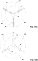
- FIGS. 1 -5 illustrate a related configuration of a mitral valve device 20.
- the device 20 has an atrial flange 22, an annulus support 24, a neck section 26 that connects the atrial flange 22 to the annulus support 24, and a valve body 28 that functions as a leaflet supporting structure.
- Each of these components is defined by struts that define cells that in turn make up a cellular matrix.
- the atrial flange 22, the annulus support 24 and the valve body 28 can be made from either a Nitinol superelastic material or stainless steel, Co-Cr based alloy, Titanium and its alloys, and other balloon expandable biocompatible materials. Other polymer biocompatible materials can also be used to fabricate these components of the device 20.
- the device 20 can be folded or compacted into a delivery system and delivered to the location of the mitral valve through transcatheter delivery (e.g., transfemoral or transapical).
- the device 20 can be released from the delivery system and positioned at the mitral valve annulus area.
- the atrial flange 22 can be placed at or on the native annulus of the mitral valve, with a portion of the atrial flange 22 extending inside the left atrium. See FIG. 5B .
- the atrial flange 22 can have a surface area that is equal or larger than the mitral annulus area.
- the atrial flange 22 can be covered by biocompatible polymer fabric, tissue or other biocompatible materials to provide a sealing effect around the device 20 and to promote tissue growth and speed up the healing effect.
- the annulus support 24 functions as an anchoring feature, and can interact with the annulus, native leaflet(s), and other internal heart structures, or subvalvular structures, to provide the desired anchoring effect. See FIG. 5B .
- the "clipping effect" created by the atrial flange 22 and the annulus support 24 can also help the device 20 to self- align and to resist potential migration during cardiac cycle.
- the components of the device 20 will be released out of the delivery system in sequence. For example, during transapical delivery, the atrial flange 22 will be deployed from the delivery system first, then the annulus support 24. In contrast, during transfemoral (trans-septal) delivery, the annulus support 24 will be deployed first, then the atrial flange 22.
- the procedures can be performed under the guidance from x-ray and/or TEE, ICE, etc.
- FIGS. 4 and 5A illustrate the typical dimensional or geometry range for each component of the device 20.
- the atrial flange 22 can either have a circular profile or a profile different from a full circle. Where the atrial flange 22 has a circular profile, the diameter of the atrial portion can be in the range from 20mm to 70mm. If the atrial flange 22 has a profile which is different from full circle, the long axis can be in the range from 20-70mm, and the shorter axis can be in the range from 15-65mm. In addition, the height H1 of the atrial flange 22 can range from 0.5mm to 20mm.
- each cell that defines the atrial flange 22 has peaks and valleys, with a rounded non-traumatic tip 34 at each peak thereof.
- the angle ⁇ 1 of the atrial flange 22 in relation to the axis of the valve body 28 can be in the range from 0 to 150 degrees.
- the atrial flange 22 can be either fully or partially covered by fabric or tissue material, or a combination of tissue and fabric materials.
- the atrial flange 22 can have barbs or spikes at the side that faces the floor of the atrium to help engage the atrial tissue and/or the annulus.
- the valve body 28 can have a height H3 in the range from 2mm to 30mm.
- the end of the valve body 28 that is closer to the atrium side can be higher and extrude above the atrial flange 22 to reduce the length of the valve body 28 inside the ventricle.
- the cross-sectional profile of the valve body 28 can either be a full circular shape or a profile that is different from a circular shape. Where the valve body 28 has a full circular profile, its diameter can be in the range from 15mm to 50mm.
- valve body 28 has a profile which is different from a circular shape
- the long axis can be in the range from 15mm to 50mm
- the shorter axis can be in the range from 10-45mm.
- the valve body 28 can also have a variable profile along its height.
- the portion of the valve body 28 near the atrial flange 22 can have an oval-shaped profile or some other profile which is different from a full circle, while the portion of the valve body 28 further away from the atrial flange 22 can have a full circular profile.
- the tissue leaflet(s) can be integrated into the valve body 28 either fully in the circular portion or encompass both circular and non-circular portions.
- the valve body 28 can be either fully or partially covered by fabric or tissue material, or a combination of tissue and fabric materials.
- the upper portion of the valve body 28 can be covered by fabric, and the lower portion of the valve body 28 can be covered by tissue, or vice versa.
- the fabric material and tissue can either be sewn/connected together first, or sewn/connected individually onto the valve body 28.
- the valve body 28 can be covered either along one surface (i.e. , internal or external surface), or along both surfaces (i.e. , internal and external surface).
- each cell that defines the valve body 28 has peaks and valleys, with a rounded nontraumatic tip 38 at the bottom thereof.
- An optional smaller diameter neck 26 provides a transition from the atrial flange 22 to the annulus support 24.
- the neck 26 extends radially inwardly from the atrial flange 22 to form a U-shaped neck 26.
- the cross-sectional profile of the neck 26 can either be a full circular shape or a profile that is different from a circular shape. Where the neck 26 has a full circular profile, its diameter can be in the range from 15 mm to 50 mm. Where the neck 26 has a profile which is different from a circular shape, the long axis can be in the range from 15 mm to 50 mm, and the shorter axis can be in the range from 10 mm to 45 mm.
- the neck 26 then transitions radially outwardly to the annulus support 24, which comprises a ring of U-shaped sections 29 that alternate with a ring of spaced- apart inverted V-shaped tabs 30.
- the neck 26 actually transitions radially outwardly to the ring of U-shaped sections 29, which extend radially outwardly before extending radially inwardly to transition to the valve body 28.
- the tabs 30 extend radially outwardly from the valve body 28 and have a generally perpendicular upward bend to define a ring that encircles the neck 26.
- the number of tabs 30 ranges from 1 to 20.
- the cross-sectional profile of the ring of tabs 30 can either be a full circular shape or a profile that is different from a circular shape.
- the ring of tabs 30 has a full circular profile, its diameter can be in the range from 15 mm to 70 mm.
- the ring of tabs 30 has a profile which is different from a circular shape, the long axis can be in the range from 15mm to 70 mm, and the shorter axis can be in the range from 10 mm to 65 mm.
- the connection point of the inverted V-shape for the tabs 30 is an enlarged point 32 whose function is to contact or press against the annulus or the native leaflet(s) of the mitral valve region of the heart to secure the device 20 at the annulus area, and therefore function as anchoring features.
- Each tab 30 has a height H4 that ranges from 0.5 mm to 10 mm.
- the tabs 30 can be either fully or partially covered by tissue or fabrics.
- the enlarged point 32 can be uncovered by fabric/tissue, while the remainder of the annulus support 24 can be covered.
- Use of fabric can promote tissue in- growth and provide better securement of the device 20 at the annulus in addition to providing additional sealing effect to prevent Perivalvular leakage (PVL).
- the ring of U-shaped sections 29 has a diameter that is greater than the diameter of the valve body 28 and the neck 26, but less than the diameter of the atrial flange 22.
- the ring of tabs 30 has a diameter that is greater than the diameter of the valve body 28 and the neck 26. but less than the diameter of the atrial flange 22.
- the tabs 30 and U-shaped sections 29 can be arranged to alternate each other in the same general ring, and can have diameters that are about the same as each other.
- each tail 36 can be formed by extending from two lower tips 38 of the valve body 28 to join a U-shaped bottom, and is used to allow a suture or other string to be tied thereto so that the suture or string can be used to adjust the position of the device 20 during deployment thereof.
- the tails 36 can also be connected with some features in the delivery system to help with (1 ) valve loading (i.e., loading the valve into the delivery system sheath): and (2) valve positioning at the annulus region of the heart.
- each tail 36 can range from 5 mm to 25 mm.
- the tail can be shape-set and bent into a shape, so that the tail(s) 36 can be extended away from the circular profile defined by the valve body 28 if desired.
- the tail 36 can suspend from the distal end of the valve body 28, and bend inwardly toward the lumen of the valve body 28.
- the tabs 30 are deployed and "seat" at/on the annulus, with a portion of the atrial flange 22 extending inside the left atrium.
- This interaction of the atrial flange 22 (from above) and the tabs 30 (from below) provide a "clipping effect” that is effective in securing the device 20 at the desired location.
- the U-shaped sections 29 can positioned at a location just below the annulus, to provide an additional sealing effect.
- the struts/cell space in the atrium can be fully, or partially, or not covered, by fabric and/or tissue.
- tissue leaflet(s) 48 of the device 20 is/are integrated into the valve body 28 to replace the function of the native mitral leaflets. As shown in FIG. 7 A and 7B , the native leaflets are positioned adjacent to, and at the outside surface of, the valve body 28.
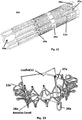
- FIGS. 6A-6B show the exemplary laser cut configuration of the device 20.
- the device 20 can be laser cut from metal or polymer tubing to reach the configuration shown in FIG. 6A .
- the cut structure would then go through shape setting, micro- blasting, and electro-polishing processes to achieve the desired profile/shape, as shown in FIGS. 1 -5B .
- the width of each strut 50 can range from 0.2 mm to 1 .5mm, and the thickness of each strut 50 can range from 0.2mm to 0.75mm.
- the length of each cell can be in the range from 2mm to 20mm.
- the number of rings along the length of the device 20 can range from 2 to 20.
- the number of cells along the circumference of the device 20 can range from 2 to 20.
- the device 20 can also be fabricated from flat sheet, and then rolled to the desired shape.
- the device 20 can be delivered according to more than one delivery method.
- a transapical delivery can be used where the atrial flange 22 can be deployed first, and provide tactile feedback during the delivery procedure.
- the annulus support 24 i.e. , tabs 30
- the tabs 30 can be deployed first, and provide tactile feedback during the delivery procedure.
- the atrial flange 22 will be released and deployed last to complete the implantation of the device 20.
- the tabs 30 can be bent inward (either up and inward, or down and inward) towards the valve body 28. When the tabs 30 are released/deployed, they can expand and press against the valve annulus or native leaflet(s).
- the device 20 can be compacted into a smaller profile for easy delivery and can be delivered and deployed once it reaches the target implant site.
- the compacted device profile can be less than 48 Fr, with 15 Fr to 40 Fr being the typical range for such applications
- FIG. 7A shows a top view of an assembled mitral valve replacement device that includes the leaflets 48 incorporated with the mitral device 20 described above.
- FIG. 7B shows a bottom view of the assembly of FIG. 7k.
- FIGS. 7A and 7B show the leaflets 48 in an opened position, so that blood flow from the left ventricle to the left atrium is prevented.
- the coaption area is between the leaflets 48 and the skirt defined by the device 20 along the internal lumen of the device 20 in the valve body 28.
- FIGS. 8A and 8B are top and bottom views, respectively, of the assembled mitral valve device of FIGS. 7 A and 7B , showing the leaflets 48 in a closed position, so that blood can flow from the left atrium to the left ventricle.
- the present invention also provides a novel leaflet configuration.
- the leaflets 48 have a configuration that is essentially the opposite of the natural leaflet configuration, such that the valve leaflets 48 open inwardly and close by expanding outwardly to contact the inner surface of the valve body 28.
- the leaflets 48 are attached to the device 20 in a manner which allows the leaflets to freely close inward to allow forward blood flow through the valve device.
- the height (depth) of the tissue leaflet(s) can vary from 2-30 mm, depending on the anatomy of the heart.
- the leaflet structure is best shown in FIGS. 7A-11 , and this embodiment shows the use of the three leaflets 48A, 48B and 48C that have been sewn together along three longitudinal stitch or suture lines 72, 74 and 76.
- the stitch lines 72, 74, 76 extend along outer edges of the leaflets 48A, 48B and 48C, and also form junction lines where the leaflet structure is connected to the valve body 28.
- the leaflets 48A, 48B and 48C are sewn along their edges to the struts 50 that make up the valve body 28.
- radial stitch or suture lines 82, 84 and 86 extend from the longitudinal stitch lines 72, 74 and 76, respectively, towards a central point 88 where a flat tip 60 is located.
- Three inner stitch or suture lines 52, 54 and 56 originate from an apex 58 where the atrial edge of the leaflets 48A, 48B, 48C are crimped together to form the central flat tip 60, so that the starting point of the stitch lines 52, 54, 56 are offset from the stitch lines 82, 84, 86.
- Each stitch line 52 is
- stitch or suture lines allows the three leaflets 48A, 48B and 48C to form an umbrella-shaped configuration for its valvular structure where the leaflets 48A, 48B, 48C will not open all the way to the top (atrial) stitch lines 82. 84, 86 under ventricular pressure to prevent the leaflet(s) from flipping over, and to minimize leakages.
- the distance between the domed ceiling defined by the leaflets 48A, 48B, 48C and the top (atrial) stitch lines 82, 84, 86 is between 0.25 mm and 10 mm.
- the leaflet structure inside the device 20 can be made using multiple leaflets 48 (as shown and described above) or a single leaflet 48.
- the single piece of leaflet 48 can be folded and sewn to the shapes shown in FIGS. 7A- 11 above.
- the leaflet design preferably uses the reverse leaflet action to regulate the blood flow between the left atrium and left ventricle.
- This reverse or "umbrella-" or “balloon- like” leaflet(s) design provides better sealing/coaptation, and also improves fatigue performance of the valve body 28 by eliminating the contraction/squeezing force/deformation that typically acts on the valve body 28 using a conventional leaflet design.
- FIGS. 12-14 illustrate a second related configuration of a mitral valve device 20, which includes the addition of clips 80.
- the device 20 in FIGS. 12-14 also have an atrial flange 22, an annulus support 24, a neck section 26 that connects the atrial flange 22 to the annulus support 24, and a valve body 28 that functions as a leaflet supporting structure, all of which can be the same as the corresponding elements in FIGS. 1 -5 .
- Each of these components is also defined by struts that define cells that in turn make up a cellular matrix.
- each clip 80 is somewhat L- shaped in that each clip 80 can extend vertically from any of the struts in the valve body 28, then horizontally in a radial direction before terminating in a short bend at its tip.
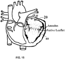
- the clips 80 function to clip or hold a portion of the native leaflet after the device 20 has been deployed, as best shown in FIG. 15 . This clipping function improves the securement of the device 20 the annulus region of the mitral valve area.
- the clipping effect provided by the atrial flange 22 and the tabs 30 is also in play here, but the clips 80 provide improved securement.
- the height H2 defines the combined height of the neck 26 and the annulus support 24, and can also be varied to accommodate for the clips 80, and can range from 0 mm to 10 mm.
- the atrial flange 22, the valve body 28 and the anchoring mechanisms e.g. , the clipping effect of the atrial flange and the tabs 30; the addition of the clips 80
- the anchoring mechanisms e.g. , the clipping effect of the atrial flange and the tabs 30; the addition of the clips 80
- the atrial flange 22 and the valve body 28 will maintain the device 20 in the desired position.
- the pressure from the left ventricle will generate an uplifting force and trying to push the device 20 up toward the atrium. That is one of the reasons why a reliable and adequate anchoring mechanism is needed to maintain the device 20 in position after the device 20 is implanted.
- the tissue leaflet(s) 48 will close the valve lumen, so that the blood will be pumped toward the aortic valve to the aorta.
- the native leaflet(s) move up (inward) toward the outside surface of the valve body 28 (wrap around), and try to seal/close the mitral valve to prevent PVL.
- the anchoring feature(s) built in the device 20 can engage the native leaflet(s) and other internal heart structure to prevent the device 20 from being pushed upward.
- the tissue leaflet(s) 48 on the device 20 will turn to a smaller profile to allow the blood to flow through and fill the left ventricle.
- the tissue leaflet(s) 48 can be operated (opened or closed) by the combined effect of blood flow, cardiac pressure, and cyclic-pulsatile movement of the supporting structure during the cardiac cycle.
- the pressure applied on to the valve body 28 by the native leaflet(s) during ventricular systole can also help to keep the device 20 from moving upward to the atrium by applying a clamping force onto the device 20.
- This is a dynamic anchoring mechanism and it takes effect only during the ventricular systole, at which stage, the device 20 under the highest uplifting force trying to push the device 20 up toward the atrium direction.
- This additional dynamic anchoring effect helps to maintain the proper position of the device 20 and reduces the anchoring force and its duration acting onto the native heart anatomy. Over time, tissue growth/healing would connect /fuse the native leaflet(s) onto the valve body 28.
- FIGS. 16-22 illustrate an embodiment of a mitral valve device 20a according to the present invention.
- the device 20a in FIGS. 16-22 also has an atrial flange 22a, an annulus support 24a, and a neck section 26a that connects the atrial flange 22a to the annulus support 24a.
- the valve body VB is now defined by the atrial flange 22a, the annulus support 24a, and a ventricular portion that is defined by V-shaped tabs 28a.
- the atrial flange 22a is similar to the atrial flange 22, except that the atrial flange 22a may have a lower profile.
- a ring of spaced-apart inverted V-shaped tabs 34a defines peaks and valleys for the atrial flange 22a, with a rounded non-traumatic tip 35a at each peak thereof.
- a plurality of leaflet holders or posts 37a extends from selected tips 35a, and each functions to support and hold portions of the leaflet. Each post 37a can be straight or curved.
- the atrial flange 22a can be placed at or on the native annulus of the mitral valve, with a portion of the atrial flange 22a extending inside the left atrium. See FIG. 20 .
- the atrial flange 22a can have a surface area that is equal or larger than the mitral annulus area.
- the atrial flange 22a can be covered by biocompatible polymer fabric, tissue or other biocompatible materials to provide a sealing effect around the device 20a and to promote tissue growth and speed up the healing effect.
- the atrial flange 22a can either have a circular profile or a profile different from a full circle (e.g., D-shaped or oval). Where the atrial flange 22a has a circular profile, the diameter of the atrial portion can be in the range from 12 mm to 75 mm. If the atrial flange 22a has a profile which is different from full circle, the long axis can be in the range from 12 mm to 75 mm, and the shorter axis can be in the range from 6 mm to 70 mm. In addition, the height H1 1 of the atrial flange 22a can range from 0.5 mm to 30 mm.
- the atrial flange 22a can be either fully or partially covered by fabric or tissue material, or a combination of tissue and fabric materials.
- the annulus support 24a functions as an anchoring feature, and can interact with the annulus, native leaflet(s), and other internal heart structures, or subvalvular structures, to provide the desired anchoring effect.
- the "clipping effect" created by the atrial flange 22a and the anchors 29a can also help the device 20a to self-align and to resist potential migration during cardiac cycle.
- the components of the device 20a will be released out of the delivery system in sequence.
- the atrial flange 22a will be deployed from the delivery system first, then the annulus support 24a, or vice versa.
- the annulus support 24a will be deployed first, then the atrial flange 22a.
- the procedures can be performed under the guidance from x-ray and/or TEE, ICE, etc.
- the neck 26a transitions from the flange 22a radially outwardly to the annulus support 24a, which comprises a ring of anchors 29a.
- the neck 26a actually transitions radially outwardly to the ring of anchors 29a, which extend radially outwardly before extending radially inwardly to transition to the V-shaped tabs 28a that extend into the ventricular portion.
- the number of anchors 29a ranges from 1 to 20.
- the cross-sectional profile of the ring of anchors 29a can either be a full circular shape or a profile (e.g., oval or D-shaped) that is different from a circular shape. Where the ring of anchors 29a has a full circular profile, its diameter can be in the range from 10 mm to 75 mm.
- the long axis can be in the range from 10 mm to 75 mm, and the shorter axis can be in the range from 5 mm to 70 mm.
- An annular clipping space is defined between the ring of anchors 29a and the atrial flange 22a, and this clipping space has a height H14 (see FIG. 19 ) that can be in the range from 0.5 mm to 30 mm.
- Each anchor 29a ends in a rounded tip 32a whose function is to contact or press against the annulus or the native leaflet(s) of the mitral valve region of the heart to secure the device 20a at the annulus area, and therefore function as anchoring features.
- Each anchor 29a can be either fully or partially covered by tissue or fabrics.
- the ring of anchors 29a has a diameter that is greater than the diameter of the valve body VB and the neck 26a, but can be less than, equal to, or even greater than the diameter of the atrial flange 22a.
- a plurality of enclosed valve holders 36a can extend from the V-shaped tabs 28a at the end of the ventricular portion. Even though a specific number of holders 36a are shown, it is possible to provide the device 20a with any number, ranging from one or more holders 36a. As best shown in FIGS. 16 , 1 9 and 21 , each holder 36a is connected to the tip 38a of a corresponding V-shaped tab 28a. The holders 36a are provided for performing the same functions as the tails 36. The length of each holder 36a can range from 5 mm to 25 mm.
- the ventricular portion can have a height H 12 in the range from 2 mm to 15 mm.
- the combined valve body VB can have a height H 13 in the range from 4 mm to 30 mm, and preferably between 8 mm to 20 mm.
- the cross-sectional profile of the ventricular portion can either be a full circular shape or a profile (e.g.. oval or D-shaped) that is different from a circular shape. Where the ventricular portion has a full circular profile, its diameter can be in the range from 10 mm to 75 mm. Where the ventricular portion has a profile which is different from a circular shape, the long axis can be in the range from 10 mm to 75 mm, and the shorter axis can be in the range from 5 mm to 70 mm.
- the ventricular portion can also have a variable profile along its height.
- the portion of the ventricular portion near the annulus support 24a can have an oval-shaped profile or some other profile which is different from a full circle, while the portion of the ventricular portion further away from the annulus support 24a can have a full circular profile.
- the ventricular portion can be positioned in the left ventricle only, in the left atrium only, or in both the left atrium and the left ventricle.
- An important aspect of this embodiment is the shortened length (i.e., height H12) of the ventricular portion, resulting in a device 20a that has a shorter profile than conventional valve replacement devices.
- the shorter profile is beneficial in that it minimizes the potential LVOT obstruction to facilitate better cardiac output.
- the shorter profile minimizes the interference with the cardiac structures in the left ventricle, such as the chordaes, and the papalary muscles, among others.
- the tissue leaflet(s) are positioned primarily within the atrial flange 22 and above the atrial flange 22 (see FIG. 23 ), so that the posts 37a can be used to hold or connect the upper portions of the leaflet(s).
- the leaflet(s) can also be integrated into the valve body VB either fully in the circular portion, or encompassing both circular and non-circular portions.
- the valve body VB can be either fully or partially covered by fabric or tissue material, or a combination of tissue and fabric materials.
- the inner surface of the valve body VB can be covered by fabric, and the outer surface can be covered by tissue, or vice versa.
- the fabric material and tissue can either be sewn/connected together first, or sewn/connected individually onto the valve body VB.
- the valve body VB can be covered either along one surface (i.e. , internal or external surface), or along both surfaces (i.e., internal and external surface).
- the ventricular portion and the holders 36a can be pulled straight and inserted into a delivery system.
- the annulus support 24a When deployed, the annulus support 24a is deployed either at the level of the native annulus or a level below the native annulus, and engages the native valvular structure through the clipping effect created by clipping the native annulus and/or native leaflets between the atrial flange 22a and the anchors 29a. See FIG. 20 .
- the atrial flange 22a is first deployed in the left atrium, and then the ventricular portion is deployed in the left ventricle (or vice versa) so that the device 20a and its leaflet assembly can experience partial or full leaflet function.
- the tabs 38a without the holder 36a are released/deployed so that the annulus ring 24a can be firmly retained at the location of the native annulus.
- the device 20a is manipulated to adjust its position, and then the tabs 38a with the holders 36a are released/deployed. This staged deployment action provides more accurate valve positioning and improved anchoring effect.
- the device 20a can be used for mitral valve replacement, or aortic valve replacement.
- the leaflet(s) can be positioned above, at or below the native annulus.
- the leaflet(s) can be positioned at or above the native annulus.
- the leaflet(s) When the device 20a has been fully deployed inside the heart at the location of a mitral valve, the leaflet(s) will be positioned primarily above the location of the native annulus. See FIG. 23 .
- the slightly high leaflet location makes it possible to reduce the length of the valve body VB length extending inside the left ventricle.
- the key advantages/novelty of the device 20 of the present invention include the following:
- the inner shaft in the delivery system may be loose from the proximal handle end of the delivery system, and pulled back proximally, so that the inner shaft will not be inside the lumen of the device. Therefore, all leaflet(s) 48 on the device 20 can move freely. This means that the device 20 can achieve a better valve function when the tails 36 are still connected with the delivery system. In other words, the fact that the leaflet(s) 48 on the device 20 are functioning during the deployment will give the physician more time to adjust the valve position/angle for optimal performance.
- adhesive bonding/interface can also be used to secure the device 20 in the native mitral position.
- biocompatible glue/adhesive to connect/fix/secure the device 20 in the mitral position.
- the biocompatible adhesive/glue can be applied on the outer surfaces of the device 20, such as along the outer surface of the valve body 28, the atrial flange 22 or any surface of the device 20 that might contact any native mitral structures, such as the annulus, the atrial surface above or on the annulus level, native leaflet(s), heart muscles, and other valvular and/or subvalvular structure(s), to maintain the position of the device 20 after implantation.
- Bioagents can also be added into the biocompatible adhesive/glue to promote healing and tissue growth.
- the adhesive/glue can be fast reacting in nature, and form a bond with the native mitral structure instantly upon contact with the blood. It can also be actuated by heat or temperature; the heat or temperature can be generated/controlled by electrolytic heating, or FR heating, or ultrasound energy, or magnetic energy, or microwave energy, or the blood temperature itself, or chemical reaction, through the portion or entire structure of the device 20.
- the adhesive/glue can be also be slow reacting in nature, and form a bond with the native mitral structure after a period of time upon contact with the blood.
- the time needed to form the bond can vary from 1 second to 2 hours, from 1 second to 28 hours, etc.
- the adhesive/glue can also have a controlled reaction in nature, and form a bond with the native mitral structure in a controlled manner upon contact with the blood.
- One example of this concept is to apply a top layer (or layers) of other biocompatible materials over the adhesive/glue layer/material on the device 20.
- the top layer(s) of the other biocompatible material can be removed or dissolved in a controlled manner either through the use of energy, heating, chemical reaction, or mechanically, or magnetically, to ensure that the adhesive/glue underneath the top layer can effectively form the bond with the native mitral structure.
- controlled manner means the time needed to form the bond can vary from 1 second to 48 hours.
Claims (9)
- Dispositif de remplacement de valve mitrale apte à être mise en œuvre à un emplacement de valve mitrale dans un cœur humain, comprenant :
une bride atriale (22a) définissant une extrémité atriale du dispositif :une partie ventriculaire (28a) définissant une extrémité ventriculaire du dispositif ;un support d'anneau (24a) agencé entre la bride atriale (22a) et la partie ventriculaire (28a), le support d'anneau (24a) présentant une bague de pièces d'ancrage (29a) s'étendant radialement à partir de celle-ci, un espace annulaire d'attache (H4, H14) étant défini entre la bride atriale (22a) et la bague de pièces d'ancrage (29a) ;la valve comprenant en outre à l'état de mise en œuvre dans le cœur humainune pluralité de moyens de retenue de feuillet (37a) agencés à l'extrémité atriale de la bride atriale (22a) ; etune pluralité de feuillets de valve (48A, 48B, 48C) fixés aux moyens de retenue de feuillets (37a) et agencés à l'intérieur de la bride atriale (22a) à un endroit situé au-dessus de l'anneau natif,caractérisé en ce quela bride atriale (22a) présente une bague de pattes (34a) espacées en forme de V inversé définissant des sommets et des creux pour la bride atriale (22a), avec une pointe arrondie non traumatique (35a) à chaque sommet de celle-ci, chaque patte s'étendant radialement vers l'extérieur jusqu'à une courbure où la patte se courbe dans un sens longitudinal du dispositif vers l'extrémité atriale, et s'étendant ensuite radialement vers l'intérieur. - Dispositif selon la revendication 1, comprenant en outre au moins un moyen de retenue de valve (36a) s'étendant à partir de l'extrémité ventriculaire de la partie ventriculaire (28a).
- Dispositif de la revendication 1, comprenant en outre un col (26a) agencé entre la bride atriale (22a) et le support d'anneau (24a).
- Dispositif selon la revendication 1, comprenant en outre un corps de valve (28), au moins une partie de la bride atriale (22a) et/ou du support d'anneau (24a) et/ou du corps de valve (28) étant recouverte de tissu.
- Dispositif selon la revendication 1, comprenant en outre un corps de valve (28), au moins une partie de la bride atriale (22a) et/ou du support d'anneau (24a) et/ou du corps de valve (28) étant recouverte d'étoffe.
- Dispositif selon la revendication 1, comprenant en outre un corps de valve (28), au moins une partie de la bride atriale (22a) et/ou du support d'anneau (24a) et/ou du corps de valve (28) étant recouverte de tissu et d'étoffe.
- Dispositif selon la revendication 6, le tissu et l'étoffe étant composés d'une couche de tissu et d'étoffe combinés.
- Dispositif selon la revendication 1, au moins une partie de la bride atriale (22a) et/ou du support d'anneau (24a) et/ou d'un corps de valve (28) étant revêtue d'un adhésif biocompatible.
- Dispositif selon la revendication 1, la partie ventriculaire présentant une hauteur (H12) comprise entre 2 mm et 15 mm.
Applications Claiming Priority (5)
| Application Number | Priority Date | Filing Date | Title |
|---|---|---|---|
| US201361887343P | 2013-10-05 | 2013-10-05 | |
| US201461927490P | 2014-01-15 | 2014-01-15 | |
| US14/279,511 US9393111B2 (en) | 2014-01-15 | 2014-05-16 | Device and method for mitral valve regurgitation treatment |
| US201462024097P | 2014-07-14 | 2014-07-14 | |
| PCT/US2014/059076 WO2015057407A1 (fr) | 2013-10-05 | 2014-10-03 | Dispositif et procédé pour procédé de régurgitation mitrale |
Publications (3)
| Publication Number | Publication Date |
|---|---|
| EP3052053A1 EP3052053A1 (fr) | 2016-08-10 |
| EP3052053A4 EP3052053A4 (fr) | 2017-06-28 |
| EP3052053B1 true EP3052053B1 (fr) | 2020-08-12 |
Family
ID=52828549
Family Applications (1)
| Application Number | Title | Priority Date | Filing Date |
|---|---|---|---|
| EP14853635.2A Active EP3052053B1 (fr) | 2013-10-05 | 2014-10-03 | Dispositif pour procédé de régurgitation mitrale |
Country Status (2)
| Country | Link |
|---|---|
| EP (1) | EP3052053B1 (fr) |
| WO (1) | WO2015057407A1 (fr) |
Families Citing this family (55)
| Publication number | Priority date | Publication date | Assignee | Title |
|---|---|---|---|---|
| US8579964B2 (en) | 2010-05-05 | 2013-11-12 | Neovasc Inc. | Transcatheter mitral valve prosthesis |
| EP2654624B1 (fr) | 2010-12-23 | 2023-10-04 | Twelve, Inc. | Système de réparation et remplacement de valvule mitrale |
| US9554897B2 (en) | 2011-04-28 | 2017-01-31 | Neovasc Tiara Inc. | Methods and apparatus for engaging a valve prosthesis with tissue |
| US9308087B2 (en) | 2011-04-28 | 2016-04-12 | Neovasc Tiara Inc. | Sequentially deployed transcatheter mitral valve prosthesis |
| CA2840084C (fr) | 2011-06-21 | 2019-11-05 | Foundry Newco Xii, Inc. | Dispositifs de valvule cardiaque prosthetiques et systemes et procedes associes |
| US9655722B2 (en) | 2011-10-19 | 2017-05-23 | Twelve, Inc. | Prosthetic heart valve devices, prosthetic mitral valves and associated systems and methods |
| US9039757B2 (en) | 2011-10-19 | 2015-05-26 | Twelve, Inc. | Prosthetic heart valve devices, prosthetic mitral valves and associated systems and methods |
| US11202704B2 (en) | 2011-10-19 | 2021-12-21 | Twelve, Inc. | Prosthetic heart valve devices, prosthetic mitral valves and associated systems and methods |
| EA201400481A1 (ru) | 2011-10-19 | 2014-10-30 | Твелв, Инк. | Искусственные сердечно-клапанные устройства, искусственные митральные клапаны и соответствующие системы и способы |
| EA201400478A1 (ru) | 2011-10-19 | 2014-10-30 | Твелв, Инк. | Устройства, системы и способы протезирования сердечного клапана |
| US9763780B2 (en) | 2011-10-19 | 2017-09-19 | Twelve, Inc. | Devices, systems and methods for heart valve replacement |
| US9579198B2 (en) | 2012-03-01 | 2017-02-28 | Twelve, Inc. | Hydraulic delivery systems for prosthetic heart valve devices and associated methods |
| US9345573B2 (en) | 2012-05-30 | 2016-05-24 | Neovasc Tiara Inc. | Methods and apparatus for loading a prosthesis onto a delivery system |
| US10849755B2 (en) | 2012-09-14 | 2020-12-01 | Boston Scientific Scimed, Inc. | Mitral valve inversion prostheses |
| US9572665B2 (en) | 2013-04-04 | 2017-02-21 | Neovasc Tiara Inc. | Methods and apparatus for delivering a prosthetic valve to a beating heart |
| US10111747B2 (en) | 2013-05-20 | 2018-10-30 | Twelve, Inc. | Implantable heart valve devices, mitral valve repair devices and associated systems and methods |
| US9901444B2 (en) * | 2013-12-17 | 2018-02-27 | Edwards Lifesciences Corporation | Inverted valve structure |
| US9782256B2 (en) * | 2015-04-27 | 2017-10-10 | Venus Medtech (Hangzhou) Inc | Heart valve assembly |
| CN111658234B (zh) | 2015-08-21 | 2023-03-10 | 托尔福公司 | 可植入心脏瓣膜装置、二尖瓣修复装置以及相关系统和方法 |
| DE202017007326U1 (de) | 2016-01-29 | 2020-10-20 | Neovasc Tiara Inc. | Klappenprothese zum Verhindern einer Abflussobstruktion |
| JP2019503813A (ja) * | 2016-02-04 | 2019-02-14 | ミリピード, インコーポレイテッドMillipede, Inc. | 僧帽弁反転プロテーゼ |
| WO2017189276A1 (fr) | 2016-04-29 | 2017-11-02 | Medtronic Vascular Inc. | Dispositifs de valve cardiaque prothétiques et systèmes et procédés associés |
| US10398553B2 (en) * | 2016-11-11 | 2019-09-03 | Evalve, Inc. | Opposing disk device for grasping cardiac valve tissue |
| EP3541462A4 (fr) | 2016-11-21 | 2020-06-17 | Neovasc Tiara Inc. | Procédés et systèmes de rétraction rapide d'un système de pose de valvule cardiaque transcathéter |
| US10575950B2 (en) | 2017-04-18 | 2020-03-03 | Twelve, Inc. | Hydraulic systems for delivering prosthetic heart valve devices and associated methods |
| US10702378B2 (en) | 2017-04-18 | 2020-07-07 | Twelve, Inc. | Prosthetic heart valve device and associated systems and methods |
| US10433961B2 (en) | 2017-04-18 | 2019-10-08 | Twelve, Inc. | Delivery systems with tethers for prosthetic heart valve devices and associated methods |
| US10792151B2 (en) | 2017-05-11 | 2020-10-06 | Twelve, Inc. | Delivery systems for delivering prosthetic heart valve devices and associated methods |
| US10646338B2 (en) | 2017-06-02 | 2020-05-12 | Twelve, Inc. | Delivery systems with telescoping capsules for deploying prosthetic heart valve devices and associated methods |
| US10709591B2 (en) | 2017-06-06 | 2020-07-14 | Twelve, Inc. | Crimping device and method for loading stents and prosthetic heart valves |
| US10786352B2 (en) | 2017-07-06 | 2020-09-29 | Twelve, Inc. | Prosthetic heart valve devices and associated systems and methods |
| US10729541B2 (en) | 2017-07-06 | 2020-08-04 | Twelve, Inc. | Prosthetic heart valve devices and associated systems and methods |
| WO2019036810A1 (fr) | 2017-08-25 | 2019-02-28 | Neovasc Tiara Inc. | Prothèse de valvule mitrale transcathéter à déploiement séquentiel |
| WO2019195860A2 (fr) | 2018-04-04 | 2019-10-10 | Vdyne, Llc | Dispositifs et procédés d'ancrage d'une valvule cardiaque transcathéter |
| US10595994B1 (en) | 2018-09-20 | 2020-03-24 | Vdyne, Llc | Side-delivered transcatheter heart valve replacement |
| US11344413B2 (en) | 2018-09-20 | 2022-05-31 | Vdyne, Inc. | Transcatheter deliverable prosthetic heart valves and methods of delivery |
| US10321995B1 (en) | 2018-09-20 | 2019-06-18 | Vdyne, Llc | Orthogonally delivered transcatheter heart valve replacement |
| US11278437B2 (en) | 2018-12-08 | 2022-03-22 | Vdyne, Inc. | Compression capable annular frames for side delivery of transcatheter heart valve replacement |
| US11071627B2 (en) | 2018-10-18 | 2021-07-27 | Vdyne, Inc. | Orthogonally delivered transcatheter heart valve frame for valve in valve prosthesis |
| US11109969B2 (en) | 2018-10-22 | 2021-09-07 | Vdyne, Inc. | Guidewire delivery of transcatheter heart valve |
| CA3118599A1 (fr) | 2018-11-08 | 2020-05-14 | Neovasc Tiara Inc. | Deploiement ventriculaire d'une prothese de valvule mitrale transcatheter |
| US11253359B2 (en) | 2018-12-20 | 2022-02-22 | Vdyne, Inc. | Proximal tab for side-delivered transcatheter heart valves and methods of delivery |
| US11273032B2 (en) | 2019-01-26 | 2022-03-15 | Vdyne, Inc. | Collapsible inner flow control component for side-deliverable transcatheter heart valve prosthesis |
| US11185409B2 (en) | 2019-01-26 | 2021-11-30 | Vdyne, Inc. | Collapsible inner flow control component for side-delivered transcatheter heart valve prosthesis |
| CN113543750A (zh) | 2019-03-05 | 2021-10-22 | 维迪内股份有限公司 | 用于正交经导管心脏瓣膜假体的三尖瓣反流控制装置 |
| US11076956B2 (en) | 2019-03-14 | 2021-08-03 | Vdyne, Inc. | Proximal, distal, and anterior anchoring tabs for side-delivered transcatheter mitral valve prosthesis |
| US11173027B2 (en) | 2019-03-14 | 2021-11-16 | Vdyne, Inc. | Side-deliverable transcatheter prosthetic valves and methods for delivering and anchoring the same |
| EP3946163A4 (fr) | 2019-04-01 | 2022-12-21 | Neovasc Tiara Inc. | Valve prothétique déployable de manière contrôlable |
| AU2020271896B2 (en) | 2019-04-10 | 2022-10-13 | Neovasc Tiara Inc. | Prosthetic valve with natural blood flow |
| JP2022530764A (ja) | 2019-05-04 | 2022-07-01 | ブイダイン,インコーポレイテッド | 生来の弁輪での側方送達される人工心臓弁を展開するための締め付けデバイス及び方法 |
| EP3972673A4 (fr) | 2019-05-20 | 2023-06-07 | Neovasc Tiara Inc. | Dispositif d'introduction avec mécanisme d'hémostase |
| AU2020295566B2 (en) | 2019-06-20 | 2023-07-20 | Neovasc Tiara Inc. | Low profile prosthetic mitral valve |
| CN114599316A (zh) | 2019-08-20 | 2022-06-07 | 维迪内股份有限公司 | 用于可侧面递送经导管人工瓣膜的递送和取回装置和方法 |
| WO2021040996A1 (fr) | 2019-08-26 | 2021-03-04 | Vdyne, Inc. | Valvules prothétiques transcathéter à pose latérale et procédés pour leurs pose et ancrage |
| US11234813B2 (en) | 2020-01-17 | 2022-02-01 | Vdyne, Inc. | Ventricular stability elements for side-deliverable prosthetic heart valves and methods of delivery |
Family Cites Families (14)
| Publication number | Priority date | Publication date | Assignee | Title |
|---|---|---|---|---|
| US6790229B1 (en) * | 1999-05-25 | 2004-09-14 | Eric Berreklouw | Fixing device, in particular for fixing to vascular wall tissue |
| US6821297B2 (en) * | 2000-02-02 | 2004-11-23 | Robert V. Snyders | Artificial heart valve, implantation instrument and method therefor |
| US20050137686A1 (en) * | 2003-12-23 | 2005-06-23 | Sadra Medical, A Delaware Corporation | Externally expandable heart valve anchor and method |
| AU2003299404A1 (en) * | 2003-12-23 | 2005-08-11 | Laboratoires Perouse | Kit which is intended to be implanted in a conduit |
| US7311730B2 (en) * | 2004-02-13 | 2007-12-25 | Shlomo Gabbay | Support apparatus and heart valve prosthesis for sutureless implantation |
| US8876894B2 (en) * | 2006-09-19 | 2014-11-04 | Medtronic Ventor Technologies Ltd. | Leaflet-sensitive valve fixation member |
| EP2901966B1 (fr) * | 2008-09-29 | 2016-06-29 | Edwards Lifesciences CardiAQ LLC | Valvule cardiaque |
| US20100217382A1 (en) * | 2009-02-25 | 2010-08-26 | Edwards Lifesciences | Mitral valve replacement with atrial anchoring |
| US8414644B2 (en) | 2009-04-15 | 2013-04-09 | Cardiaq Valve Technologies, Inc. | Vascular implant and delivery system |
| AU2010315030B2 (en) * | 2009-11-05 | 2016-03-10 | The Trustees Of The University Of Pennsylvania | Valve prosthesis |
| US8657872B2 (en) * | 2010-07-19 | 2014-02-25 | Jacques Seguin | Cardiac valve repair system and methods of use |
| US9132009B2 (en) * | 2010-07-21 | 2015-09-15 | Mitraltech Ltd. | Guide wires with commissural anchors to advance a prosthetic valve |
| EP3459500B1 (fr) * | 2010-09-23 | 2020-09-16 | Edwards Lifesciences CardiAQ LLC | Valvules cardiaques de remplacement et dispositifs |
| US9308087B2 (en) * | 2011-04-28 | 2016-04-12 | Neovasc Tiara Inc. | Sequentially deployed transcatheter mitral valve prosthesis |
-
2014
- 2014-10-03 WO PCT/US2014/059076 patent/WO2015057407A1/fr active Application Filing
- 2014-10-03 EP EP14853635.2A patent/EP3052053B1/fr active Active
Non-Patent Citations (1)
| Title |
|---|
| None * |
Also Published As
| Publication number | Publication date |
|---|---|
| EP3052053A4 (fr) | 2017-06-28 |
| WO2015057407A1 (fr) | 2015-04-23 |
| EP3052053A1 (fr) | 2016-08-10 |
Similar Documents
| Publication | Publication Date | Title |
|---|---|---|
| US10426605B2 (en) | Device and method for mitral valve regurgitation treatment | |
| EP3052053B1 (fr) | Dispositif pour procédé de régurgitation mitrale | |
| US9393111B2 (en) | Device and method for mitral valve regurgitation treatment | |
| CA2922123C (fr) | Dispositif et utilisation pour un traitement de regurgitation mitrale | |
| US20200360138A1 (en) | Method and Design for a Mitral Regurgitation Treatment Device | |
| US10856974B2 (en) | Heart valve repair and replacement | |
| US20210038381A1 (en) | Transcatheter prosthetic valve for mitral or tricuspid valve replacement | |
| EP3769721B1 (fr) | Système d'accueil de valvule cardiaque | |
| CN106963519B (zh) | 假体二尖瓣接合增强装置 | |
| EP2999433B1 (fr) | Valve transcathéter prothétique pour remplacement de valve mitrale ou tricuspide | |
| JP6545665B2 (ja) | 埋込可能な心臓弁デバイス、僧帽弁修復デバイス、および関連するシステムおよび方法 | |
| JP2023184533A (ja) | 人工弁尖器具 | |
| WO2016073741A1 (fr) | Prothèse transcathéter de valvule cardiaque | |
| US10058422B2 (en) | Transcatheter valve stent anchors | |
| JP2018528810A (ja) | 埋込可能な心臓弁デバイス、僧帽弁修復デバイス、ならびに関連するシステム及び方法 | |
| CA2865074A1 (fr) | Support de valvule cardiaque a anneau unique | |
| US20140155993A1 (en) | Device for mitigating or preventing paravalvular leaks |
Legal Events
| Date | Code | Title | Description |
|---|---|---|---|
| PUAI | Public reference made under article 153(3) epc to a published international application that has entered the european phase |
Free format text: ORIGINAL CODE: 0009012 |
|
| 17P | Request for examination filed |
Effective date: 20160308 |
|
| AK | Designated contracting states |
Kind code of ref document: A1 Designated state(s): AL AT BE BG CH CY CZ DE DK EE ES FI FR GB GR HR HU IE IS IT LI LT LU LV MC MK MT NL NO PL PT RO RS SE SI SK SM TR |
|
| AX | Request for extension of the european patent |
Extension state: BA ME |
|
| DAX | Request for extension of the european patent (deleted) | ||
| A4 | Supplementary search report drawn up and despatched |
Effective date: 20170530 |
|
| RIC1 | Information provided on ipc code assigned before grant |
Ipc: A61F 2/24 20060101AFI20170523BHEP |
|
| STAA | Information on the status of an ep patent application or granted ep patent |
Free format text: STATUS: EXAMINATION IS IN PROGRESS |
|
| 17Q | First examination report despatched |
Effective date: 20190327 |
|
| GRAP | Despatch of communication of intention to grant a patent |
Free format text: ORIGINAL CODE: EPIDOSNIGR1 |
|
| STAA | Information on the status of an ep patent application or granted ep patent |
Free format text: STATUS: GRANT OF PATENT IS INTENDED |
|
| INTG | Intention to grant announced |
Effective date: 20200316 |
|
| RIN1 | Information on inventor provided before grant (corrected) |
Inventor name: MENG, LEI Inventor name: MA, JIANXIANG Inventor name: MA, JIANLU Inventor name: HUO, YONG Inventor name: LI, TIANZHU Inventor name: ZHAO, JINHONG |
|
| GRAS | Grant fee paid |
Free format text: ORIGINAL CODE: EPIDOSNIGR3 |
|
| GRAA | (expected) grant |
Free format text: ORIGINAL CODE: 0009210 |
|
| STAA | Information on the status of an ep patent application or granted ep patent |
Free format text: STATUS: THE PATENT HAS BEEN GRANTED |
|
| AK | Designated contracting states |
Kind code of ref document: B1 Designated state(s): AL AT BE BG CH CY CZ DE DK EE ES FI FR GB GR HR HU IE IS IT LI LT LU LV MC MK MT NL NO PL PT RO RS SE SI SK SM TR |
|
| REG | Reference to a national code |
Ref country code: CH Ref legal event code: EP |
|
| REG | Reference to a national code |
Ref country code: IE Ref legal event code: FG4D |
|
| REG | Reference to a national code |
Ref country code: DE Ref legal event code: R096 Ref document number: 602014068982 Country of ref document: DE |
|
| REG | Reference to a national code |
Ref country code: AT Ref legal event code: REF Ref document number: 1300781 Country of ref document: AT Kind code of ref document: T Effective date: 20200915 |
|
| REG | Reference to a national code |
Ref country code: LT Ref legal event code: MG4D |
|
| REG | Reference to a national code |
Ref country code: NL Ref legal event code: MP Effective date: 20200812 |
|
| PG25 | Lapsed in a contracting state [announced via postgrant information from national office to epo] |
Ref country code: FI Free format text: LAPSE BECAUSE OF FAILURE TO SUBMIT A TRANSLATION OF THE DESCRIPTION OR TO PAY THE FEE WITHIN THE PRESCRIBED TIME-LIMIT Effective date: 20200812 Ref country code: HR Free format text: LAPSE BECAUSE OF FAILURE TO SUBMIT A TRANSLATION OF THE DESCRIPTION OR TO PAY THE FEE WITHIN THE PRESCRIBED TIME-LIMIT Effective date: 20200812 Ref country code: LT Free format text: LAPSE BECAUSE OF FAILURE TO SUBMIT A TRANSLATION OF THE DESCRIPTION OR TO PAY THE FEE WITHIN THE PRESCRIBED TIME-LIMIT Effective date: 20200812 Ref country code: NO Free format text: LAPSE BECAUSE OF FAILURE TO SUBMIT A TRANSLATION OF THE DESCRIPTION OR TO PAY THE FEE WITHIN THE PRESCRIBED TIME-LIMIT Effective date: 20201112 Ref country code: GR Free format text: LAPSE BECAUSE OF FAILURE TO SUBMIT A TRANSLATION OF THE DESCRIPTION OR TO PAY THE FEE WITHIN THE PRESCRIBED TIME-LIMIT Effective date: 20201113 Ref country code: BG Free format text: LAPSE BECAUSE OF FAILURE TO SUBMIT A TRANSLATION OF THE DESCRIPTION OR TO PAY THE FEE WITHIN THE PRESCRIBED TIME-LIMIT Effective date: 20201112 Ref country code: SE Free format text: LAPSE BECAUSE OF FAILURE TO SUBMIT A TRANSLATION OF THE DESCRIPTION OR TO PAY THE FEE WITHIN THE PRESCRIBED TIME-LIMIT Effective date: 20200812 |
|
| REG | Reference to a national code |
Ref country code: AT Ref legal event code: MK05 Ref document number: 1300781 Country of ref document: AT Kind code of ref document: T Effective date: 20200812 |
|
| PG25 | Lapsed in a contracting state [announced via postgrant information from national office to epo] |
Ref country code: RS Free format text: LAPSE BECAUSE OF FAILURE TO SUBMIT A TRANSLATION OF THE DESCRIPTION OR TO PAY THE FEE WITHIN THE PRESCRIBED TIME-LIMIT Effective date: 20200812 Ref country code: NL Free format text: LAPSE BECAUSE OF FAILURE TO SUBMIT A TRANSLATION OF THE DESCRIPTION OR TO PAY THE FEE WITHIN THE PRESCRIBED TIME-LIMIT Effective date: 20200812 Ref country code: PL Free format text: LAPSE BECAUSE OF FAILURE TO SUBMIT A TRANSLATION OF THE DESCRIPTION OR TO PAY THE FEE WITHIN THE PRESCRIBED TIME-LIMIT Effective date: 20200812 Ref country code: LV Free format text: LAPSE BECAUSE OF FAILURE TO SUBMIT A TRANSLATION OF THE DESCRIPTION OR TO PAY THE FEE WITHIN THE PRESCRIBED TIME-LIMIT Effective date: 20200812 Ref country code: IS Free format text: LAPSE BECAUSE OF FAILURE TO SUBMIT A TRANSLATION OF THE DESCRIPTION OR TO PAY THE FEE WITHIN THE PRESCRIBED TIME-LIMIT Effective date: 20201212 |
|
| PG25 | Lapsed in a contracting state [announced via postgrant information from national office to epo] |
Ref country code: EE Free format text: LAPSE BECAUSE OF FAILURE TO SUBMIT A TRANSLATION OF THE DESCRIPTION OR TO PAY THE FEE WITHIN THE PRESCRIBED TIME-LIMIT Effective date: 20200812 Ref country code: SM Free format text: LAPSE BECAUSE OF FAILURE TO SUBMIT A TRANSLATION OF THE DESCRIPTION OR TO PAY THE FEE WITHIN THE PRESCRIBED TIME-LIMIT Effective date: 20200812 Ref country code: RO Free format text: LAPSE BECAUSE OF FAILURE TO SUBMIT A TRANSLATION OF THE DESCRIPTION OR TO PAY THE FEE WITHIN THE PRESCRIBED TIME-LIMIT Effective date: 20200812 Ref country code: CZ Free format text: LAPSE BECAUSE OF FAILURE TO SUBMIT A TRANSLATION OF THE DESCRIPTION OR TO PAY THE FEE WITHIN THE PRESCRIBED TIME-LIMIT Effective date: 20200812 Ref country code: DK Free format text: LAPSE BECAUSE OF FAILURE TO SUBMIT A TRANSLATION OF THE DESCRIPTION OR TO PAY THE FEE WITHIN THE PRESCRIBED TIME-LIMIT Effective date: 20200812 |
|
| REG | Reference to a national code |
Ref country code: DE Ref legal event code: R097 Ref document number: 602014068982 Country of ref document: DE |
|
| PG25 | Lapsed in a contracting state [announced via postgrant information from national office to epo] |
Ref country code: AL Free format text: LAPSE BECAUSE OF FAILURE TO SUBMIT A TRANSLATION OF THE DESCRIPTION OR TO PAY THE FEE WITHIN THE PRESCRIBED TIME-LIMIT Effective date: 20200812 Ref country code: AT Free format text: LAPSE BECAUSE OF FAILURE TO SUBMIT A TRANSLATION OF THE DESCRIPTION OR TO PAY THE FEE WITHIN THE PRESCRIBED TIME-LIMIT Effective date: 20200812 Ref country code: ES Free format text: LAPSE BECAUSE OF FAILURE TO SUBMIT A TRANSLATION OF THE DESCRIPTION OR TO PAY THE FEE WITHIN THE PRESCRIBED TIME-LIMIT Effective date: 20200812 |
|
| REG | Reference to a national code |
Ref country code: CH Ref legal event code: PL |
|
| PLBE | No opposition filed within time limit |
Free format text: ORIGINAL CODE: 0009261 |
|
| STAA | Information on the status of an ep patent application or granted ep patent |
Free format text: STATUS: NO OPPOSITION FILED WITHIN TIME LIMIT |
|
| PG25 | Lapsed in a contracting state [announced via postgrant information from national office to epo] |
Ref country code: MC Free format text: LAPSE BECAUSE OF FAILURE TO SUBMIT A TRANSLATION OF THE DESCRIPTION OR TO PAY THE FEE WITHIN THE PRESCRIBED TIME-LIMIT Effective date: 20200812 Ref country code: LU Free format text: LAPSE BECAUSE OF NON-PAYMENT OF DUE FEES Effective date: 20201003 Ref country code: SK Free format text: LAPSE BECAUSE OF FAILURE TO SUBMIT A TRANSLATION OF THE DESCRIPTION OR TO PAY THE FEE WITHIN THE PRESCRIBED TIME-LIMIT Effective date: 20200812 |
|
| REG | Reference to a national code |
Ref country code: BE Ref legal event code: MM Effective date: 20201031 |
|
| 26N | No opposition filed |
Effective date: 20210514 |
|
| PG25 | Lapsed in a contracting state [announced via postgrant information from national office to epo] |
Ref country code: IT Free format text: LAPSE BECAUSE OF FAILURE TO SUBMIT A TRANSLATION OF THE DESCRIPTION OR TO PAY THE FEE WITHIN THE PRESCRIBED TIME-LIMIT Effective date: 20200812 |
|
| PG25 | Lapsed in a contracting state [announced via postgrant information from national office to epo] |
Ref country code: SI Free format text: LAPSE BECAUSE OF FAILURE TO SUBMIT A TRANSLATION OF THE DESCRIPTION OR TO PAY THE FEE WITHIN THE PRESCRIBED TIME-LIMIT Effective date: 20200812 Ref country code: LI Free format text: LAPSE BECAUSE OF NON-PAYMENT OF DUE FEES Effective date: 20201031 Ref country code: BE Free format text: LAPSE BECAUSE OF NON-PAYMENT OF DUE FEES Effective date: 20201031 Ref country code: CH Free format text: LAPSE BECAUSE OF NON-PAYMENT OF DUE FEES Effective date: 20201031 |
|
| PG25 | Lapsed in a contracting state [announced via postgrant information from national office to epo] |
Ref country code: IE Free format text: LAPSE BECAUSE OF NON-PAYMENT OF DUE FEES Effective date: 20201003 |
|
| REG | Reference to a national code |
Ref country code: DE Ref legal event code: R081 Ref document number: 602014068982 Country of ref document: DE Owner name: SINOMED CARDIOVITA TECHNOLOGY INC., CN Free format text: FORMER OWNER: SINO MEDICAL SCIENCES TECHNOLOGY, INC., TIANJIN, CN |
|
| REG | Reference to a national code |
Ref country code: GB Ref legal event code: 732E Free format text: REGISTERED BETWEEN 20220414 AND 20220420 |
|
| PG25 | Lapsed in a contracting state [announced via postgrant information from national office to epo] |
Ref country code: TR Free format text: LAPSE BECAUSE OF FAILURE TO SUBMIT A TRANSLATION OF THE DESCRIPTION OR TO PAY THE FEE WITHIN THE PRESCRIBED TIME-LIMIT Effective date: 20200812 Ref country code: MT Free format text: LAPSE BECAUSE OF FAILURE TO SUBMIT A TRANSLATION OF THE DESCRIPTION OR TO PAY THE FEE WITHIN THE PRESCRIBED TIME-LIMIT Effective date: 20200812 Ref country code: CY Free format text: LAPSE BECAUSE OF FAILURE TO SUBMIT A TRANSLATION OF THE DESCRIPTION OR TO PAY THE FEE WITHIN THE PRESCRIBED TIME-LIMIT Effective date: 20200812 |
|
| PG25 | Lapsed in a contracting state [announced via postgrant information from national office to epo] |
Ref country code: MK Free format text: LAPSE BECAUSE OF FAILURE TO SUBMIT A TRANSLATION OF THE DESCRIPTION OR TO PAY THE FEE WITHIN THE PRESCRIBED TIME-LIMIT Effective date: 20200812 |
|
| PG25 | Lapsed in a contracting state [announced via postgrant information from national office to epo] |
Ref country code: PT Free format text: LAPSE BECAUSE OF FAILURE TO SUBMIT A TRANSLATION OF THE DESCRIPTION OR TO PAY THE FEE WITHIN THE PRESCRIBED TIME-LIMIT Effective date: 20200812 |
|
| PGFP | Annual fee paid to national office [announced via postgrant information from national office to epo] |
Ref country code: GB Payment date: 20231020 Year of fee payment: 10 |
|
| PGFP | Annual fee paid to national office [announced via postgrant information from national office to epo] |
Ref country code: FR Payment date: 20231026 Year of fee payment: 10 Ref country code: DE Payment date: 20231026 Year of fee payment: 10 |