EP3051690A1 - Wireless power transmission device - Google Patents
Wireless power transmission device Download PDFInfo
- Publication number
- EP3051690A1 EP3051690A1 EP13894055.6A EP13894055A EP3051690A1 EP 3051690 A1 EP3051690 A1 EP 3051690A1 EP 13894055 A EP13894055 A EP 13894055A EP 3051690 A1 EP3051690 A1 EP 3051690A1
- Authority
- EP
- European Patent Office
- Prior art keywords
- power
- input
- coil
- ground
- feeding
- Prior art date
- Legal status (The legal status is an assumption and is not a legal conclusion. Google has not performed a legal analysis and makes no representation as to the accuracy of the status listed.)
- Withdrawn
Links
Images


Classifications
-
- H—ELECTRICITY
- H02—GENERATION; CONVERSION OR DISTRIBUTION OF ELECTRIC POWER
- H02J—CIRCUIT ARRANGEMENTS OR SYSTEMS FOR SUPPLYING OR DISTRIBUTING ELECTRIC POWER; SYSTEMS FOR STORING ELECTRIC ENERGY
- H02J50/00—Circuit arrangements or systems for wireless supply or distribution of electric power
- H02J50/10—Circuit arrangements or systems for wireless supply or distribution of electric power using inductive coupling
-
- B—PERFORMING OPERATIONS; TRANSPORTING
- B60—VEHICLES IN GENERAL
- B60L—PROPULSION OF ELECTRICALLY-PROPELLED VEHICLES; SUPPLYING ELECTRIC POWER FOR AUXILIARY EQUIPMENT OF ELECTRICALLY-PROPELLED VEHICLES; ELECTRODYNAMIC BRAKE SYSTEMS FOR VEHICLES IN GENERAL; MAGNETIC SUSPENSION OR LEVITATION FOR VEHICLES; MONITORING OPERATING VARIABLES OF ELECTRICALLY-PROPELLED VEHICLES; ELECTRIC SAFETY DEVICES FOR ELECTRICALLY-PROPELLED VEHICLES
- B60L53/00—Methods of charging batteries, specially adapted for electric vehicles; Charging stations or on-board charging equipment therefor; Exchange of energy storage elements in electric vehicles
- B60L53/10—Methods of charging batteries, specially adapted for electric vehicles; Charging stations or on-board charging equipment therefor; Exchange of energy storage elements in electric vehicles characterised by the energy transfer between the charging station and the vehicle
- B60L53/12—Inductive energy transfer
- B60L53/122—Circuits or methods for driving the primary coil, e.g. supplying electric power to the coil
-
- H—ELECTRICITY
- H02—GENERATION; CONVERSION OR DISTRIBUTION OF ELECTRIC POWER
- H02J—CIRCUIT ARRANGEMENTS OR SYSTEMS FOR SUPPLYING OR DISTRIBUTING ELECTRIC POWER; SYSTEMS FOR STORING ELECTRIC ENERGY
- H02J50/00—Circuit arrangements or systems for wireless supply or distribution of electric power
- H02J50/10—Circuit arrangements or systems for wireless supply or distribution of electric power using inductive coupling
- H02J50/12—Circuit arrangements or systems for wireless supply or distribution of electric power using inductive coupling of the resonant type
-
- H—ELECTRICITY
- H02—GENERATION; CONVERSION OR DISTRIBUTION OF ELECTRIC POWER
- H02J—CIRCUIT ARRANGEMENTS OR SYSTEMS FOR SUPPLYING OR DISTRIBUTING ELECTRIC POWER; SYSTEMS FOR STORING ELECTRIC ENERGY
- H02J50/00—Circuit arrangements or systems for wireless supply or distribution of electric power
- H02J50/80—Circuit arrangements or systems for wireless supply or distribution of electric power involving the exchange of data, concerning supply or distribution of electric power, between transmitting devices and receiving devices
-
- H—ELECTRICITY
- H02—GENERATION; CONVERSION OR DISTRIBUTION OF ELECTRIC POWER
- H02J—CIRCUIT ARRANGEMENTS OR SYSTEMS FOR SUPPLYING OR DISTRIBUTING ELECTRIC POWER; SYSTEMS FOR STORING ELECTRIC ENERGY
- H02J2310/00—The network for supplying or distributing electric power characterised by its spatial reach or by the load
- H02J2310/40—The network being an on-board power network, i.e. within a vehicle
- H02J2310/48—The network being an on-board power network, i.e. within a vehicle for electric vehicles [EV] or hybrid vehicles [HEV]
-
- H—ELECTRICITY
- H02—GENERATION; CONVERSION OR DISTRIBUTION OF ELECTRIC POWER
- H02J—CIRCUIT ARRANGEMENTS OR SYSTEMS FOR SUPPLYING OR DISTRIBUTING ELECTRIC POWER; SYSTEMS FOR STORING ELECTRIC ENERGY
- H02J7/00—Circuit arrangements for charging or depolarising batteries or for supplying loads from batteries
- H02J7/0029—Circuit arrangements for charging or depolarising batteries or for supplying loads from batteries with safety or protection devices or circuits
- H02J7/00304—Overcurrent protection
-
- H—ELECTRICITY
- H02—GENERATION; CONVERSION OR DISTRIBUTION OF ELECTRIC POWER
- H02J—CIRCUIT ARRANGEMENTS OR SYSTEMS FOR SUPPLYING OR DISTRIBUTING ELECTRIC POWER; SYSTEMS FOR STORING ELECTRIC ENERGY
- H02J7/00—Circuit arrangements for charging or depolarising batteries or for supplying loads from batteries
- H02J7/0029—Circuit arrangements for charging or depolarising batteries or for supplying loads from batteries with safety or protection devices or circuits
- H02J7/00308—Overvoltage protection
-
- Y—GENERAL TAGGING OF NEW TECHNOLOGICAL DEVELOPMENTS; GENERAL TAGGING OF CROSS-SECTIONAL TECHNOLOGIES SPANNING OVER SEVERAL SECTIONS OF THE IPC; TECHNICAL SUBJECTS COVERED BY FORMER USPC CROSS-REFERENCE ART COLLECTIONS [XRACs] AND DIGESTS
- Y02—TECHNOLOGIES OR APPLICATIONS FOR MITIGATION OR ADAPTATION AGAINST CLIMATE CHANGE
- Y02T—CLIMATE CHANGE MITIGATION TECHNOLOGIES RELATED TO TRANSPORTATION
- Y02T10/00—Road transport of goods or passengers
- Y02T10/60—Other road transportation technologies with climate change mitigation effect
- Y02T10/70—Energy storage systems for electromobility, e.g. batteries
-
- Y—GENERAL TAGGING OF NEW TECHNOLOGICAL DEVELOPMENTS; GENERAL TAGGING OF CROSS-SECTIONAL TECHNOLOGIES SPANNING OVER SEVERAL SECTIONS OF THE IPC; TECHNICAL SUBJECTS COVERED BY FORMER USPC CROSS-REFERENCE ART COLLECTIONS [XRACs] AND DIGESTS
- Y02—TECHNOLOGIES OR APPLICATIONS FOR MITIGATION OR ADAPTATION AGAINST CLIMATE CHANGE
- Y02T—CLIMATE CHANGE MITIGATION TECHNOLOGIES RELATED TO TRANSPORTATION
- Y02T10/00—Road transport of goods or passengers
- Y02T10/60—Other road transportation technologies with climate change mitigation effect
- Y02T10/7072—Electromobility specific charging systems or methods for batteries, ultracapacitors, supercapacitors or double-layer capacitors
-
- Y—GENERAL TAGGING OF NEW TECHNOLOGICAL DEVELOPMENTS; GENERAL TAGGING OF CROSS-SECTIONAL TECHNOLOGIES SPANNING OVER SEVERAL SECTIONS OF THE IPC; TECHNICAL SUBJECTS COVERED BY FORMER USPC CROSS-REFERENCE ART COLLECTIONS [XRACs] AND DIGESTS
- Y02—TECHNOLOGIES OR APPLICATIONS FOR MITIGATION OR ADAPTATION AGAINST CLIMATE CHANGE
- Y02T—CLIMATE CHANGE MITIGATION TECHNOLOGIES RELATED TO TRANSPORTATION
- Y02T90/00—Enabling technologies or technologies with a potential or indirect contribution to GHG emissions mitigation
- Y02T90/10—Technologies relating to charging of electric vehicles
- Y02T90/12—Electric charging stations
-
- Y—GENERAL TAGGING OF NEW TECHNOLOGICAL DEVELOPMENTS; GENERAL TAGGING OF CROSS-SECTIONAL TECHNOLOGIES SPANNING OVER SEVERAL SECTIONS OF THE IPC; TECHNICAL SUBJECTS COVERED BY FORMER USPC CROSS-REFERENCE ART COLLECTIONS [XRACs] AND DIGESTS
- Y02—TECHNOLOGIES OR APPLICATIONS FOR MITIGATION OR ADAPTATION AGAINST CLIMATE CHANGE
- Y02T—CLIMATE CHANGE MITIGATION TECHNOLOGIES RELATED TO TRANSPORTATION
- Y02T90/00—Enabling technologies or technologies with a potential or indirect contribution to GHG emissions mitigation
- Y02T90/10—Technologies relating to charging of electric vehicles
- Y02T90/14—Plug-in electric vehicles
-
- Y—GENERAL TAGGING OF NEW TECHNOLOGICAL DEVELOPMENTS; GENERAL TAGGING OF CROSS-SECTIONAL TECHNOLOGIES SPANNING OVER SEVERAL SECTIONS OF THE IPC; TECHNICAL SUBJECTS COVERED BY FORMER USPC CROSS-REFERENCE ART COLLECTIONS [XRACs] AND DIGESTS
- Y02—TECHNOLOGIES OR APPLICATIONS FOR MITIGATION OR ADAPTATION AGAINST CLIMATE CHANGE
- Y02T—CLIMATE CHANGE MITIGATION TECHNOLOGIES RELATED TO TRANSPORTATION
- Y02T90/00—Enabling technologies or technologies with a potential or indirect contribution to GHG emissions mitigation
- Y02T90/10—Technologies relating to charging of electric vehicles
- Y02T90/16—Information or communication technologies improving the operation of electric vehicles
Definitions
- the present invention relates to a contactless power transmission apparatus used for charging or the like of an electric propulsion vehicle such as an electric automobile or plug-in hybrid automobile.
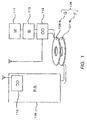
- FIG. 1 is a schematic diagram illustrating a configuration of contactless power transmission apparatus 106 according to the related art.
- a power feeding apparatus (primary side) F connected to a power panel of power supply 109 on a ground side is disposed so as to face a power receiving apparatus (secondary side) G with an air gap interposed in between and without any physical contact during power supply.
- This air gap is a void space.
- Power receiving apparatus G is mounted on an electric propulsion vehicle.
- an alternating current (AC) is given to primary coil 107 (power feeding coil) provided for power feeding apparatus F and a magnetic field is generated
- secondary coil 108 power receiving coil
- Power is thereby transmitted contactlessly from primary coil 107 to secondary coil 108.
- Power receiving apparatus G is connected to, for example, vehicle-mounted battery 110, and vehicle-mounted battery 110 is charged with the power transmitted as described above. Vehicle-mounted motor 111 is driven by the power stored in battery 110. Note that necessary information is exchanged between power feeding apparatus F and power receiving apparatus G during contactless power supply processing via, for example, wireless communication apparatus 112.
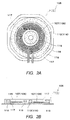
- FIGS. 2A and 2B are schematic diagrams illustrating an inner structure of power feeding apparatus F and power receiving apparatus G. Particularly, FIG. 2A is a schematic diagram illustrating an inner structure of power feeding apparatus F seen from above and power receiving apparatus G seen from below. FIG 2B is a schematic diagram illustrating an inner structure of power feeding apparatus F and power receiving apparatus G seen laterally.
- power feeding apparatus F includes primary coil 107, primary magnetic core 113, back plate 115 and cover 116 or the like.
- power receiving apparatus G has a structure symmetric with respect to power feeding apparatus F and includes secondary coil 108, secondary magnetic core 114, back plate 115, and cover 116, for example. Surfaces of primary coil 107 and primary magnetic core 113 and surfaces of secondary coil 108 and secondary magnetic core 114 are respectively covered fixedly with mold resin 117 into which foamed material 118 is mixed.
- primary coil 107 of power feeding apparatus F and secondary coil 108 of power receiving apparatus G are formed by spirally winding litz wires 121 and 122 which are a bundle of a plurality of elemental wires.
- primary coil 107 of power feeding apparatus F on the ground side is disposed so as to face secondary coil 108 of power receiving apparatus G mounted on the vehicle.
- primary coil 107 and secondary coil 108 facing each other, and a magnetic field generated from primary coil 107 interlinking with secondary coil 108 over a wide range, power is transmitted contactlessly.
- Wireless communication apparatus 112 performs processing such as information processing, encryption processing for preventing crosstalk, and device authentication processing in parallel, and thus the speed of wireless communication is restricted to a certain degree.
- a relay or the like for switching to another device is disposed between power receiving apparatus G and battery 110.
- the relay for switching to another device is opened due to some malfunction during power transmission, thus leading to the open-load condition of power receiving apparatus G.
- the speed of wireless communication is insufficient in this situation and thus allows the power transmission to continue from power feeding apparatus F, the inside of power receiving apparatus G may suffer overvoltage, which may break power receiving apparatus G.
- power feeding apparatus F detect abnormal conditions with power feeding apparatus F alone and handle the abnormal conditions including the overvoltage condition of power receiving apparatus G in consideration of a case where malfunction occurs to the wireless communication itself.
- An object of the present invention is to provide a contactless power transmission apparatus capable of preventing breaking a power receiving apparatus by detecting input of a power supply, and by stopping supply of a current to a primary coil when the variation width of magnitude of the input is equal to or more than a predetermined value.
- the present invention employs the following configuration.
- a contactless power transmission apparatus includes: a primary coil that generates a magnetic field through a current supplied from a power supply; an input detection section that detects a magnitude of input from the power supply; a control section that controls the current supplied from the power supply to the primary coil based on a detection signal of the input detection section; and a secondary coil that receives power through a magnetic field from the primary coil, in which the control section stops supply of a current to the primary coil when an input variation equal to or more than a predetermined value is detected based on a detection signal of the input detection section.
- the primary coil and the secondary coil are opposite to each other with a gap interposed therebetween, and thus the degree of magnetic coupling of the primary coil relative to the secondary coil is low, with apparent impedance being small. That is, the steepness (Q) of resonance is high, and the frequency characteristics of input power, output power, and the like are extremely steep.
- the input power increases or decreases abruptly when the apparent impedance seen from the primary coil varies in the case where a malfunction occurs to a relay connecting a rectification section with a battery or the like, which is a load, and causes a sudden open-load condition, or in the case where a short-circuit breakdown or the like of the secondary coil occurs.
- the present invention includes an input detection section that detects the magnitude of power or the like input to a power supply, and a control section that controls a current supplied from the power supply to a primary coil based on a detection signal of the input detection section; when the control section detects a variation in magnitude of input equal to or more than a predetermined value, supply of a current to the primary coil is stopped, and thus it is possible to detect abnormality in a secondary coil, a rectification section, or the like without using wireless communication to quickly move on to a safe operation.
- a contactless power transmission apparatus includes: a primary coil that generates a magnetic field through a current supplied from a power supply; an input detection section that detects a magnitude of input from the power supply; a control section that controls the current supplied from the power supply to the primary coil based on a detection signal of the input detection section; and a secondary coil that receives power through a magnetic field from the primary coil, in which the control section stops supply of a current to the primary coil when an input variation equal to or more than a predetermined value is detected based on a detection signal of the input detection section.
- Such a configuration allows the control section to control the power supply to stop supply of a current to the primary coil when the control section detects a variation in magnitude of input equal to or more than a predetermined value. Therefore, it is possible to detect abnormality in the secondary coil, the rectification section, or the like without using wireless communication to quickly move on to a safe operation.
- FIG. 4 is a block diagram of a contactless power transmission apparatus according to the present invention.
- FIGS. 5 and 6 are outline views of a vehicle placed in a parking space.
- the contactless power transmission apparatus is composed of power feeding apparatus 1 placed, for example, in a parking space, and power receiving apparatus 8 mounted on, for example, an electric propulsion vehicle.
- Power feeding apparatus 1 includes primary-side rectification circuit 3 connected to AC power supply 2, inverter section 4, ground-side coil unit 5, control section (power-feeding-apparatus side control section, for example, microcomputer) 6, and input detection section (for example, current transformer that detects an input current) 23.
- Primary-side rectification circuit 3 and inverter section 4 constitute power control apparatus 7 which is a high-frequency power supply.
- power receiving apparatus 8 includes vehicle-side coil unit 9, secondary-side rectification section 10 which is a rectification section that rectifies power, battery 11 which is a load, and control section (power-receiving-apparatus side control section, for example, microcomputer) 12.
- AC power supply 2 is a 200 V commercial power supply which is a low-frequency AC power supply, and is connected to an input end of primary-side rectification circuit 3, an output end of primary-side rectification circuit 3 is connected to an input end of inverter section 4, and an output end of inverter section 4 is connected to ground-side coil unit 5.
- an output end of vehicle-side coil unit 9 is connected to an input end of secondary-side rectification section 10, and an output end of secondary-side rectification section 10 is connected to battery 11.
- Ground-side coil unit 5 is installed on the ground, and power control apparatus 7 is installed in an upright position at a predetermined distance from, for example, ground-side coil unit 5 (see FIG. 5 ). Meanwhile, vehicle-side coil unit 9 is attached to, for example, a body bottom section (e.g., chassis).
- a body bottom section e.g., chassis
- Ground-side coil 13 which is a primary coil and ground-side resonance capacitor 14 are installed inside ground-side coil unit 5 which is placed on the ground. Ground-side coil 13 and ground-side resonance capacitor 14 are connected in series, and their other terminals are connected to the output end of inverter section 4.
- vehicle-side coil 15 which is a secondary coil and vehicle-side resonance capacitor 16 are installed inside vehicle-side coil unit 9 attached to the body bottom section.
- Vehicle-side coil 15 and vehicle-side resonance capacitor 16 are connected in series, and their other terminals are connected to the input end of secondary-side rectification section 10.
- a resonance frequency between ground-side coil 13 and ground-side resonance capacitor 14 is set to be substantially identical to a resonance frequency between vehicle-side coil 15 and vehicle-side resonance capacitor 16.
- the number of turns of each of ground-side coil 13 and vehicle-side coil 15 is 30. Note that, in FIG. 7 to be described hereinafter, the number of turns of each of ground-side coil 13 and vehicle-side coil 15 is illustrated in a simplified manner.
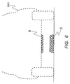
- FIG. 7 is a cross-sectional view of portions of ground-side coil 13 and vehicle-side coil 15 in particular in ground-side coil unit 5 and vehicle-side coil unit 9 of the contactless power transmission apparatus of the present embodiment.
- ground-side coil unit 5 includes base 17 fixed on the ground side, ground-side coil 13 installed on base 17, and cover 18 which is a case that covers ground-side coil 13.
- Vehicle-side coil unit 9 includes base 19 fixed to the body, vehicle-side coil 15 installed on base 19, and cover 20 which is a case that covers vehicle-side coil 15.
- Ground-side coil 13 is formed by spirally winding coil wire 21 to form a plurality of turns
- vehicle-side coil 15 is formed by spirally winding coil wire 22 to form a plurality of turns.
- Ground-side coil 13 and vehicle-side coil 15 each have a circular-plate shape and are designed to have substantially the same outer and inner diameters.
- Litz wires are used as coil wires 21 and 22 of ground-side coil 13 and vehicle-side coil 15, but other conductive wires may also be used.
- power-feeding-apparatus side control section 6 wirelessly communicates with power-receiving-apparatus side control section 12, and power-receiving-apparatus side control section 12 determines a power command value according to a detected residual voltage of battery 11 and sends the determined power command value to power-feeding-apparatus side control section 6.
- power-receiving-apparatus side control section 12 transmits the voltage and current of battery 11 and receiving power calculated therefrom to power-feeding-apparatus side control section 6.
- Power-feeding-apparatus side control section 6 compares the received power command value with the actual receiving power, and drives inverter section 4 so as to obtain receiving power corresponding to the power command value within a range not exceeding rated input power of power feeding apparatus 1.
- power-feeding-apparatus side control section 6 starts driving inverter section 4 at a high frequency, by a predetermined width, apart from a resonance frequency between ground-side coil 13 and ground-side resonance capacitor 14 and a resonance frequency between vehicle-side coil 15 and vehicle-side resonance capacitor 16.
- the reason that driving is started at a high frequency apart from the resonance frequencies is that being apart from the resonance frequencies makes the impedance seen from ground-side coil 13 and inverter section 4 higher and makes it possible to suppress the output power to a low level and avoid a transient overloaded operation state (overvoltage and overcurrent) immediately after the driving starts.
- power-feeding-apparatus side control section 6 causes the drive frequency of inverter section 4 to gradually decrease to approach the resonance frequencies.
- the impedance seen from ground-side coil 13 and inverter section 4 decreases and the receiving power gradually increases.
- power-receiving-apparatus side control section 12 detects receiving power and changes a power command value for power-feeding-apparatus side control section 6 so that no overcurrent or overvoltage is applied to battery 11.
- current transformer 23 which is an input detection section outputs a voltage in accordance with the magnitude of an input current input to power feeding apparatus 1, and then outputs a detection signal in accordance with the magnitude of the input current to power-feeding-apparatus side control section 6 via a circuit (not illustrated) that rectifies an output voltage.
- Power-feeding-apparatus side control section 6 recognizes the magnitude of an input current from the detection signal, estimates the input current from a voltage of a commercial power supply connected to power feeding apparatus 1, and controls inverter section 4 to autonomously limit transmission power to power receiving apparatus 8 so as not to exceed rated input power.
- power-feeding-apparatus side control section 6 sets the drive frequency of inverter section 4 to be higher. Further, when the input power does not reach the rated input power and the receiving power of power receiving apparatus 8 does not reach the power command value, either, power-feeding-apparatus side control section 6 sets the drive frequency of inverter section 4 to be lower.
- vehicle-side coil unit 9 is located opposite to ground-side coil unit 5 by moving the body (vehicle) as appropriate.
- Power-feeding-apparatus side control section 6 controls driving of inverter section 4 to thereby cause ground-side coil 13 to generate a high-frequency magnetic field.
- vehicle-side coil 15 an induced electromotive force is generated by the magnetic field of ground-side coil 13 disposed opposite thereto and a high-frequency current is induced in vehicle-side coil 15.
- Power receiving apparatus 8 extracts power using this high-frequency current and charges battery 11 with the extracted power.
- power-feeding-apparatus side control section 6 and power-receiving-apparatus side control section 12 pair with each other in order to prevent crosstalk and erroneous operation due to noise or the like from the outside, and communicate information while sending and receiving authentication signals.
- information is encrypted for wireless communication, and decoding processing is performed on the receiving side.
- processing is highly concentrated on the wireless communication portions of power-feeding-apparatus side control section 6 and power-receiving-apparatus side control section 12.
- an increase in the speed of wireless communication may broaden the wireless communication frequency band, which may affect the wireless communication in other channels communicating at the same frequency, or may increase heat generation of the wireless communication portions of power-feeding-apparatus side control section 6 and power-receiving-apparatus side control section 12.
- the wireless communication portions of power-feeding-apparatus side control section 6 and power-receiving-apparatus side control section 12 must reduce the influence received by the outside noise while suppressing the influence on other wireless communication, so that there is a limit to the amount of information communicable by the wireless communication and the speed thereof.
- ground-side coil 13 and vehicle-side coil 15 are opposite to each other, there is a distance therebetween, and thus the degree of magnetic coupling of ground-side coil 13 relative to vehicle-side coil 15 is low, with apparent impedance being small. That is, the steepness (Q) of resonance is high, and the frequency characteristics of input power, output power, and the like are extremely steep.
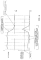
- FIG. 8 is a graph in which the horizontal axis represents a frequency and the vertical axis represents input power.
- the inductance decreases, and thus the resonance frequency becomes higher, which causes the frequency characteristic of input power to shift toward a higher frequency. Therefore, when inverter section 4 continues the operation at the same frequency, the input power increases abruptly.
- the impedance seen from ground-side coil 13 varies, and thus the resonance frequency becomes lower, which causes the frequency characteristic of the input power to shift toward a lower frequency. Therefore, the input power decreases abruptly in this case.
- power, a voltage, and a current to be received by power-receiving apparatus 8 also vary largely, and thus it is possible for power-receiving-apparatus side control section 12 to detect the variations in power, a voltage, and a current and transmit information to power-feeding-apparatus side control section 6 by wireless communication.
- the variations in power, a voltage, and a current to be received by power-receiving apparatus 8 during abnormality are very fast variations of about several hundred ⁇ sec, and thus it is difficult for the wireless communication which performs mutual authentication, encryption and decoding, while suppressing the influence on other communications to secure sufficiently faster speed than the variation speeds of power, a voltage, and a current.
- There is a fear that insufficient transmission of information by wireless communication may lead to secondary damage to the components of power feeding apparatus 1 and power receiving apparatus 8 due to excessive input power.
- power feeding apparatus 1 includes current transformer 23 which is an input detection section.
- the detection signal of current transformer 23 is input to power-feeding-apparatus side control section 6.
- FIG. 9 is a graph illustrating temporal variations in an input current during power feeding operation recognized by power-feeding-apparatus side control section 6 and in an absolute value of a variation width of the input current.
- power-feeding-apparatus side control section 6 recognizes, through AD conversion, a detection signal in accordance with the magnitude of an input current at a predetermined time interval.
- power-feeding-apparatus side control section 6 retains therein a threshold of acceptable variation width of an input current within a predetermined period of time, and compares an input current newly recognized through AD conversion this time with an input current having been recognized through AD conversion up to this time to determine whether the input current exceeds the threshold of acceptable variation width.
- power-feeding-apparatus side control section 6 immediately stops driving inverter section 4 irrespective of wireless communication from power-receiving-apparatus side control section 12 to stop feeding power to power receiving apparatus 8.
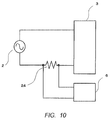
- the present embodiment provides an example of using current transformer 23 for an input detection section; however, as illustrated, for example, in FIG. 10 , resistor 24 may be inserted in series into a power line connecting AC power supply 2 to power feeding apparatus 1 to detect a voltage generated across the terminals of resistor 24 for detection of magnitude of the input.
- a suitable input detection section may be provided, depending on power feeding apparatus 1.
- FIG. 11 is a graph illustrating temporal variations in an input current during power feeding operation recognized by power-feeding-apparatus side control section 6 and in an absolute value of a variation width of the input current.
- power-feeding-apparatus side control section 6 has a first threshold of acceptable variation width of magnitude of the input and a second threshold of acceptable variation width greater than that of the first threshold.
- power-feeding-apparatus side control section 6 When the variation width of magnitude of the input exceeds the first threshold due to, for example, the operation of a vehicle-side component, but does not exceed the second threshold, power-feeding-apparatus side control section 6 does not stop driving inverter section 4 and controls the input power to be decreased, thus making possible to continue stable power feeding.
- the variation width of magnitude of the input exceeds the second threshold due to, for example, the malfunction of a component power-feeding-apparatus side control section 6 performs a control to immediately stop driving inverter section 4 to thereby reduce the number of stopping times of power feeding apparatus 1, thus making possible to continue stable power feeding.
- relay 25 which is a connection section for switching between conduction and cutoff is typically provided between power receiving apparatus 8 and battery 11, in order to avoid electrical interference with other vehicle-side components.
- battery 11 is disposed outside power receiving apparatus 8.
- the relay 25 is controlled by power-receiving-apparatus side control section 12 so as to switch between conduction and cutoff, and is designed to be conducted during power transmission from power feeding apparatus 1 to power receiving apparatus 8 and to be cut off in other occasions.
- power-feeding-apparatus side control section 6 can perform detection and can perform stopping without any problem, and thus can also serve the role of relay 25 of detecting erroneous operation, which relay 25 is a connection section for switching between conduction and cutoff disposed between power receiving apparatus 8 and battery 11.
- FIG. 13 is a graph illustrating temporal variations in an input current during power feeding operation recognized by power-feeding-apparatus side control section 6 and in an absolute value of a variation width of the input current.
- the variation in the voltage of battery 11 leads to the variation in apparent impedance seen from ground-side coil 13; thus, for example, when the control of power-feeding-apparatus side control section 6 over inverter section 4 is slower than the variation in the voltage of battery 11, variations in input power, receiving power, and the like occur. Therefore, by providing a threshold for a variation which occurs for a shorter period of time than the time of the variation of input magnitude caused by the variation in apparent impedance due to, for example, the variation in the voltage of battery 11 which may occur during a normal operation, it becomes possible for power-feeding-apparatus side control section 6 to detect only the period of abnormality.
- a threshold of acceptable variation width of magnitude of the input within a predetermined period of time which is retained by power-feeding-apparatus side control section 6, to be greater than the variation width of magnitude of the input within a predetermined period of time which may occur during normal operation, it becomes possible to detect only the period of abnormality.
- the present embodiment provides an example of detecting the period of abnormality with the variation in magnitude of the input.
- the voltage or current depends on apparent impedance and input power. Therefore, when the apparent impedance becomes lower due to some malfunction than apparent impedance during normal operation, and as a result the frequency characteristic of the input power varies to cause the input power to be lowered, there are almost no variations in coil currents and voltages, causing a case where detection is not possible during abnormality. Accordingly, it is desirable to perform detection with input magnitude.
- the present invention is also applicable to a configuration in which the power receiving apparatus is disposed on the ground side and the power feeding apparatus is disposed on the vehicle side.
- the present invention it is possible to detect abnormality in a secondary coil, a rectification section, or the like without using wireless communication to quickly move on to a safe operation. Therefore, it is applicable to a power feeding apparatus and a power receiving apparatus of contactless power transmission used for charging or the like of an electric propulsion vehicle such as an electric automobile or plug-in hybrid automobile.
Landscapes
- Engineering & Computer Science (AREA)
- Power Engineering (AREA)
- Computer Networks & Wireless Communication (AREA)
- Transportation (AREA)
- Mechanical Engineering (AREA)
- Electric Propulsion And Braking For Vehicles (AREA)
- Charge And Discharge Circuits For Batteries Or The Like (AREA)
Abstract
Description
- The present invention relates to a contactless power transmission apparatus used for charging or the like of an electric propulsion vehicle such as an electric automobile or plug-in hybrid automobile.
-
FIG. 1 is a schematic diagram illustrating a configuration of contactlesspower transmission apparatus 106 according to the related art. InFIG. 1 , a power feeding apparatus (primary side) F connected to a power panel ofpower supply 109 on a ground side is disposed so as to face a power receiving apparatus (secondary side) G with an air gap interposed in between and without any physical contact during power supply. This air gap is a void space. Power receiving apparatus G is mounted on an electric propulsion vehicle. In such a configuration, when an alternating current (AC) is given to primary coil 107 (power feeding coil) provided for power feeding apparatus F and a magnetic field is generated, an induced electromotive force is generated in secondary coil 108 (power receiving coil) provided for power receiving apparatus G. Power is thereby transmitted contactlessly fromprimary coil 107 tosecondary coil 108. - Power receiving apparatus G is connected to, for example, vehicle-mounted
battery 110, and vehicle-mountedbattery 110 is charged with the power transmitted as described above. Vehicle-mountedmotor 111 is driven by the power stored inbattery 110. Note that necessary information is exchanged between power feeding apparatus F and power receiving apparatus G during contactless power supply processing via, for example,wireless communication apparatus 112. -
FIGS. 2A and 2B are schematic diagrams illustrating an inner structure of power feeding apparatus F and power receiving apparatus G. Particularly,FIG. 2A is a schematic diagram illustrating an inner structure of power feeding apparatus F seen from above and power receiving apparatus G seen from below.FIG 2B is a schematic diagram illustrating an inner structure of power feeding apparatus F and power receiving apparatus G seen laterally. - In
FIGS. 2A and 2B , power feeding apparatus F includesprimary coil 107, primarymagnetic core 113,back plate 115 andcover 116 or the like. Briefly, power receiving apparatus G has a structure symmetric with respect to power feeding apparatus F and includessecondary coil 108, secondarymagnetic core 114,back plate 115, andcover 116, for example. Surfaces ofprimary coil 107 and primarymagnetic core 113 and surfaces ofsecondary coil 108 and secondarymagnetic core 114 are respectively covered fixedly withmold resin 117 into whichfoamed material 118 is mixed. - Here, a relationship between
primary coil 107 of power feeding apparatus F andsecondary coil 108 of power receiving apparatus G in the related art will be described using a schematic diagram inFIG. 3 . As illustrated inFIG. 3 ,primary coil 107 andsecondary coil 108 are formed by spirally windinglitz wires primary coil 107 of power feeding apparatus F on the ground side is disposed so as to facesecondary coil 108 of power receiving apparatus G mounted on the vehicle. Withprimary coil 107 andsecondary coil 108 facing each other, and a magnetic field generated fromprimary coil 107 interlinking withsecondary coil 108 over a wide range, power is transmitted contactlessly. - Japanese Patent Application Laid-Open No.
2008-87733 - As illustrated in
FIG. 3 , there is an air gap betweenprimary coil 107 andsecondary coil 108 in the contactless power transmission apparatus according to the related art. Thus, information on voltage, current, and power or the like at power receiving apparatus G is transmitted to power feeding apparatus F bywireless communication apparatus 112.Wireless communication apparatus 112 performs processing such as information processing, encryption processing for preventing crosstalk, and device authentication processing in parallel, and thus the speed of wireless communication is restricted to a certain degree. - Further, when some malfunction occurs in power receiving apparatus G, it is necessary to stop power transmission from power feeding apparatus F immediately. For example, a relay or the like for switching to another device is disposed between power receiving apparatus G and
battery 110. Consider a situation where the relay for switching to another device is opened due to some malfunction during power transmission, thus leading to the open-load condition of power receiving apparatus G. When the speed of wireless communication is insufficient in this situation and thus allows the power transmission to continue from power feeding apparatus F, the inside of power receiving apparatus G may suffer overvoltage, which may break power receiving apparatus G. - It is desirable that power feeding apparatus F detect abnormal conditions with power feeding apparatus F alone and handle the abnormal conditions including the overvoltage condition of power receiving apparatus G in consideration of a case where malfunction occurs to the wireless communication itself.
- An object of the present invention is to provide a contactless power transmission apparatus capable of preventing breaking a power receiving apparatus by detecting input of a power supply, and by stopping supply of a current to a primary coil when the variation width of magnitude of the input is equal to or more than a predetermined value.
- In order to achieve the above described object, the present invention employs the following configuration.
- A contactless power transmission apparatus according to an aspect of the present invention includes: a primary coil that generates a magnetic field through a current supplied from a power supply; an input detection section that detects a magnitude of input from the power supply; a control section that controls the current supplied from the power supply to the primary coil based on a detection signal of the input detection section; and a secondary coil that receives power through a magnetic field from the primary coil, in which the control section stops supply of a current to the primary coil when an input variation equal to or more than a predetermined value is detected based on a detection signal of the input detection section.
- The primary coil and the secondary coil are opposite to each other with a gap interposed therebetween, and thus the degree of magnetic coupling of the primary coil relative to the secondary coil is low, with apparent impedance being small. That is, the steepness (Q) of resonance is high, and the frequency characteristics of input power, output power, and the like are extremely steep.
- For example, the input power increases or decreases abruptly when the apparent impedance seen from the primary coil varies in the case where a malfunction occurs to a relay connecting a rectification section with a battery or the like, which is a load, and causes a sudden open-load condition, or in the case where a short-circuit breakdown or the like of the secondary coil occurs.
- The present invention includes an input detection section that detects the magnitude of power or the like input to a power supply, and a control section that controls a current supplied from the power supply to a primary coil based on a detection signal of the input detection section; when the control section detects a variation in magnitude of input equal to or more than a predetermined value, supply of a current to the primary coil is stopped, and thus it is possible to detect abnormality in a secondary coil, a rectification section, or the like without using wireless communication to quickly move on to a safe operation.
-
-
FIG. 1 is a schematic diagram illustrating a configuration of a contactless power transmission apparatus according to the related art; -
FIGS. 2A and 2B are diagrams illustrating an inner structure of a power receiving apparatus (power feeding apparatus) disposed opposite to a power feeding apparatus (power receiving apparatus) inFIG. 1 ; -
FIG. 3 is a cross-sectional view of the power feeding apparatus and the power receiving apparatus inFIGS. 2A and 2B ; -
FIG. 4 is a block diagram of a contactless power transmission apparatus according to an embodiment of the present invention; -
FIG. 5 is an outline view of the contactless power transmission apparatus inFIG. 4 ; -
FIG. 6 is an outline view of the contactless power transmission apparatus inFIG. 4 ; -
FIG. 7 is a cross-sectional view of a ground-side coil unit and a vehicle-side coil unit; -
FIG. 8 is a graph illustrating a variation in frequency characteristic of input power during normal operation and abnormal operation; -
FIG. 9 is a graph illustrating temporal variations in an input current recognized by a power-feeding-apparatus side control section and in an absolute value of a variation width of the input current; -
FIG. 10 is a block diagram ofVariation 1 of an input detection section; -
FIG. 11 is a graph ofVariation 2 illustrating temporal variations in an input current recognized by a power-feeding-apparatus side control section and in an absolute value of a variation width of the input current; -
FIG. 12 is a block diagram ofVariation 3 of a contactless power transmission apparatus; and -
FIG. 13 is a graph ofVariation 4 illustrating temporal variations in an input current recognized by a power-feeding-apparatus side control section and in an absolute value of a variation width of the input current. - A contactless power transmission apparatus according to an aspect of the present invention includes: a primary coil that generates a magnetic field through a current supplied from a power supply; an input detection section that detects a magnitude of input from the power supply; a control section that controls the current supplied from the power supply to the primary coil based on a detection signal of the input detection section; and a secondary coil that receives power through a magnetic field from the primary coil, in which the control section stops supply of a current to the primary coil when an input variation equal to or more than a predetermined value is detected based on a detection signal of the input detection section.
- Such a configuration allows the control section to control the power supply to stop supply of a current to the primary coil when the control section detects a variation in magnitude of input equal to or more than a predetermined value. Therefore, it is possible to detect abnormality in the secondary coil, the rectification section, or the like without using wireless communication to quickly move on to a safe operation.
- Hereinafter, an embodiment of the present invention will be described with reference to the accompanying drawings. Note that the present embodiment is not intended to limit the present invention.
-
FIG. 4 is a block diagram of a contactless power transmission apparatus according to the present invention.FIGS. 5 and6 are outline views of a vehicle placed in a parking space. As illustrated inFIGS. 4 ,5 and6 , the contactless power transmission apparatus is composed ofpower feeding apparatus 1 placed, for example, in a parking space, andpower receiving apparatus 8 mounted on, for example, an electric propulsion vehicle. -
Power feeding apparatus 1 includes primary-side rectification circuit 3 connected toAC power supply 2,inverter section 4, ground-side coil unit 5, control section (power-feeding-apparatus side control section, for example, microcomputer) 6, and input detection section (for example, current transformer that detects an input current) 23. Primary-side rectification circuit 3 andinverter section 4 constitutepower control apparatus 7 which is a high-frequency power supply. Further,power receiving apparatus 8 includes vehicle-side coil unit 9, secondary-side rectification section 10 which is a rectification section that rectifies power,battery 11 which is a load, and control section (power-receiving-apparatus side control section, for example, microcomputer) 12. - In
power feeding apparatus 1,AC power supply 2 is a 200 V commercial power supply which is a low-frequency AC power supply, and is connected to an input end of primary-side rectification circuit 3, an output end of primary-side rectification circuit 3 is connected to an input end ofinverter section 4, and an output end ofinverter section 4 is connected to ground-side coil unit 5. Meanwhile, inpower receiving apparatus 8, an output end of vehicle-side coil unit 9 is connected to an input end of secondary-side rectification section 10, and an output end of secondary-side rectification section 10 is connected tobattery 11. - Ground-
side coil unit 5 is installed on the ground, andpower control apparatus 7 is installed in an upright position at a predetermined distance from, for example, ground-side coil unit 5 (seeFIG. 5 ). Meanwhile, vehicle-side coil unit 9 is attached to, for example, a body bottom section (e.g., chassis). - Ground-
side coil 13 which is a primary coil and ground-side resonance capacitor 14 are installed inside ground-side coil unit 5 which is placed on the ground. Ground-side coil 13 and ground-side resonance capacitor 14 are connected in series, and their other terminals are connected to the output end ofinverter section 4. - Similarly, vehicle-
side coil 15 which is a secondary coil and vehicle-side resonance capacitor 16 are installed inside vehicle-side coil unit 9 attached to the body bottom section. Vehicle-side coil 15 and vehicle-side resonance capacitor 16 are connected in series, and their other terminals are connected to the input end of secondary-side rectification section 10. - A resonance frequency between ground-
side coil 13 and ground-side resonance capacitor 14 is set to be substantially identical to a resonance frequency between vehicle-side coil 15 and vehicle-side resonance capacitor 16. Specifically, in the present embodiment, the number of turns of each of ground-side coil 13 and vehicle-side coil 15 is 30. Note that, inFIG. 7 to be described hereinafter, the number of turns of each of ground-side coil 13 and vehicle-side coil 15 is illustrated in a simplified manner. -
FIG. 7 is a cross-sectional view of portions of ground-side coil 13 and vehicle-side coil 15 in particular in ground-side coil unit 5 and vehicle-side coil unit 9 of the contactless power transmission apparatus of the present embodiment. As illustrated inFIG. 7 , ground-side coil unit 5 includesbase 17 fixed on the ground side, ground-side coil 13 installed onbase 17, and cover 18 which is a case that covers ground-side coil 13. Vehicle-side coil unit 9 includesbase 19 fixed to the body, vehicle-side coil 15 installed onbase 19, and cover 20 which is a case that covers vehicle-side coil 15. - Ground-
side coil 13 is formed by spirally windingcoil wire 21 to form a plurality of turns, and similarly, vehicle-side coil 15 is formed by spirally windingcoil wire 22 to form a plurality of turns. Ground-side coil 13 and vehicle-side coil 15 each have a circular-plate shape and are designed to have substantially the same outer and inner diameters. Litz wires are used ascoil wires side coil 13 and vehicle-side coil 15, but other conductive wires may also be used. - In the above-described configuration, power-feeding-apparatus
side control section 6 wirelessly communicates with power-receiving-apparatusside control section 12, and power-receiving-apparatusside control section 12 determines a power command value according to a detected residual voltage ofbattery 11 and sends the determined power command value to power-feeding-apparatusside control section 6. At the same time, power-receiving-apparatusside control section 12 transmits the voltage and current ofbattery 11 and receiving power calculated therefrom to power-feeding-apparatusside control section 6. Power-feeding-apparatusside control section 6 compares the received power command value with the actual receiving power, and drivesinverter section 4 so as to obtain receiving power corresponding to the power command value within a range not exceeding rated input power ofpower feeding apparatus 1. - More specifically, power-feeding-apparatus
side control section 6 starts drivinginverter section 4 at a high frequency, by a predetermined width, apart from a resonance frequency between ground-side coil 13 and ground-side resonance capacitor 14 and a resonance frequency between vehicle-side coil 15 and vehicle-side resonance capacitor 16. The reason that driving is started at a high frequency apart from the resonance frequencies is that being apart from the resonance frequencies makes the impedance seen from ground-side coil 13 andinverter section 4 higher and makes it possible to suppress the output power to a low level and avoid a transient overloaded operation state (overvoltage and overcurrent) immediately after the driving starts. - After that, power-feeding-apparatus
side control section 6 causes the drive frequency ofinverter section 4 to gradually decrease to approach the resonance frequencies. The impedance seen from ground-side coil 13 andinverter section 4 decreases and the receiving power gradually increases. - During a power supply, power-receiving-apparatus
side control section 12 detects receiving power and changes a power command value for power-feeding-apparatusside control section 6 so that no overcurrent or overvoltage is applied tobattery 11. - In
power feeding apparatus 1,current transformer 23 which is an input detection section outputs a voltage in accordance with the magnitude of an input current input topower feeding apparatus 1, and then outputs a detection signal in accordance with the magnitude of the input current to power-feeding-apparatusside control section 6 via a circuit (not illustrated) that rectifies an output voltage. Power-feeding-apparatusside control section 6 recognizes the magnitude of an input current from the detection signal, estimates the input current from a voltage of a commercial power supply connected topower feeding apparatus 1, and controlsinverter section 4 to autonomously limit transmission power to power receivingapparatus 8 so as not to exceed rated input power. When the input power exceeds the rated input power, or when the receiving power ofpower receiving apparatus 8 exceeds the power command value, power-feeding-apparatusside control section 6 sets the drive frequency ofinverter section 4 to be higher. Further, when the input power does not reach the rated input power and the receiving power ofpower receiving apparatus 8 does not reach the power command value, either, power-feeding-apparatusside control section 6 sets the drive frequency ofinverter section 4 to be lower. - As illustrated in
FIGS. 5 and6 , when power is supplied frompower feeding apparatus 1 to power receivingapparatus 8, vehicle-side coil unit 9 is located opposite to ground-side coil unit 5 by moving the body (vehicle) as appropriate. Power-feeding-apparatusside control section 6 controls driving ofinverter section 4 to thereby cause ground-side coil 13 to generate a high-frequency magnetic field. In vehicle-side coil 15, an induced electromotive force is generated by the magnetic field of ground-side coil 13 disposed opposite thereto and a high-frequency current is induced in vehicle-side coil 15.Power receiving apparatus 8 extracts power using this high-frequency current and chargesbattery 11 with the extracted power. - At this time, power-feeding-apparatus
side control section 6 and power-receiving-apparatusside control section 12 pair with each other in order to prevent crosstalk and erroneous operation due to noise or the like from the outside, and communicate information while sending and receiving authentication signals. At the same time, in order to prevent interception of wireless communication by others, or reception of misinformation transmitted intentionally, information is encrypted for wireless communication, and decoding processing is performed on the receiving side. Thus, processing is highly concentrated on the wireless communication portions of power-feeding-apparatusside control section 6 and power-receiving-apparatusside control section 12. Further, an increase in the speed of wireless communication may broaden the wireless communication frequency band, which may affect the wireless communication in other channels communicating at the same frequency, or may increase heat generation of the wireless communication portions of power-feeding-apparatusside control section 6 and power-receiving-apparatusside control section 12. - Therefore, the wireless communication portions of power-feeding-apparatus
side control section 6 and power-receiving-apparatusside control section 12 must reduce the influence received by the outside noise while suppressing the influence on other wireless communication, so that there is a limit to the amount of information communicable by the wireless communication and the speed thereof. - Meanwhile, while ground-
side coil 13 and vehicle-side coil 15 are opposite to each other, there is a distance therebetween, and thus the degree of magnetic coupling of ground-side coil 13 relative to vehicle-side coil 15 is low, with apparent impedance being small. That is, the steepness (Q) of resonance is high, and the frequency characteristics of input power, output power, and the like are extremely steep. - For example, as in the case where vehicle-
side coil 15 undergoes variation in inductance due to layer short, disconnection or the like, or as in the case where the malfunction of a vehicle-side component causes opening/short-circuit, when the apparent impedance seen from ground-side coil 13 varies, frequency characteristics of input power, output power, and the like vary, thus causing the input power to increase or decrease abruptly at a frequency at whichinverter section 4 operates. -
FIG. 8 is a graph in which the horizontal axis represents a frequency and the vertical axis represents input power. For example, when vehicle-side coil 15 is short-circuited due to layer short, the inductance decreases, and thus the resonance frequency becomes higher, which causes the frequency characteristic of input power to shift toward a higher frequency. Therefore, wheninverter section 4 continues the operation at the same frequency, the input power increases abruptly. On the other hand, when a component ofpower receiving apparatus 8 undergoes an open breakdown, the impedance seen from ground-side coil 13 varies, and thus the resonance frequency becomes lower, which causes the frequency characteristic of the input power to shift toward a lower frequency. Therefore, the input power decreases abruptly in this case. - Due to the above-mentioned malfunction or the like, power, a voltage, and a current to be received by power-receiving
apparatus 8 also vary largely, and thus it is possible for power-receiving-apparatusside control section 12 to detect the variations in power, a voltage, and a current and transmit information to power-feeding-apparatusside control section 6 by wireless communication. - However, the variations in power, a voltage, and a current to be received by power-receiving
apparatus 8 during abnormality are very fast variations of about several hundred µsec, and thus it is difficult for the wireless communication which performs mutual authentication, encryption and decoding, while suppressing the influence on other communications to secure sufficiently faster speed than the variation speeds of power, a voltage, and a current. There is a fear that insufficient transmission of information by wireless communication may lead to secondary damage to the components ofpower feeding apparatus 1 andpower receiving apparatus 8 due to excessive input power. - In the present embodiment,
power feeding apparatus 1 includescurrent transformer 23 which is an input detection section. The detection signal ofcurrent transformer 23 is input to power-feeding-apparatusside control section 6.FIG. 9 is a graph illustrating temporal variations in an input current during power feeding operation recognized by power-feeding-apparatusside control section 6 and in an absolute value of a variation width of the input current. As illustrated inFIG. 9 , power-feeding-apparatusside control section 6 recognizes, through AD conversion, a detection signal in accordance with the magnitude of an input current at a predetermined time interval. Further, power-feeding-apparatusside control section 6 retains therein a threshold of acceptable variation width of an input current within a predetermined period of time, and compares an input current newly recognized through AD conversion this time with an input current having been recognized through AD conversion up to this time to determine whether the input current exceeds the threshold of acceptable variation width. When the input current exceeds the threshold of acceptable variation width, power-feeding-apparatusside control section 6 immediately stops drivinginverter section 4 irrespective of wireless communication from power-receiving-apparatusside control section 12 to stop feeding power to power receivingapparatus 8. Therefore, for example, as in the case where vehicle-side coil 15 undergoes variation in inductance due to layer short or disconnection, or as in the case where the malfunction of a vehicle-side component causes opening/short-circuit, even when the apparent impedance seen from ground-side coil 13 varies to thereby cause the input power to increase or decrease abruptly or cause the power to be received bypower receiving apparatus 8 to increase or decrease abruptly, it is possible to securely stop feeding power to power receivingapparatus 8. - The present embodiment provides an example of using
current transformer 23 for an input detection section; however, as illustrated, for example, inFIG. 10 ,resistor 24 may be inserted in series into a power line connectingAC power supply 2 topower feeding apparatus 1 to detect a voltage generated across the terminals ofresistor 24 for detection of magnitude of the input. A suitable input detection section may be provided, depending onpower feeding apparatus 1. - In addition, while an example is provided in which power-feeding-apparatus
side control section 6 immediately stops drivinginverter section 4 when the input current exceeds the threshold of acceptable variation width of magnitude of the input; however, power-feeding-apparatusside control section 6 is not construed to be limited to this example. Similarly toFIG. 9 ,FIG. 11 is a graph illustrating temporal variations in an input current during power feeding operation recognized by power-feeding-apparatusside control section 6 and in an absolute value of a variation width of the input current. - Even when, for example, a heater or the like which is a vehicle-side component is connected to between
power receiving apparatus 8 andbattery 11 to allow the heater or the like to be operated or stopped by the vehicle-side control section, the apparent impedance seen from ground-side coil 13 varies, and thus similar variations in input power, receiving power, and the like occur. Here,battery 11 is disposed outsidepower receiving apparatus 8. However, the variation is smaller than that in the case of opening/short-circuit due to malfunction of a component, and thus variation in magnitude of the input also becomes smaller. Accordingly, power-feeding-apparatusside control section 6 has a first threshold of acceptable variation width of magnitude of the input and a second threshold of acceptable variation width greater than that of the first threshold. When the variation width of magnitude of the input exceeds the first threshold due to, for example, the operation of a vehicle-side component, but does not exceed the second threshold, power-feeding-apparatusside control section 6 does not stop drivinginverter section 4 and controls the input power to be decreased, thus making possible to continue stable power feeding. When the variation width of magnitude of the input exceeds the second threshold due to, for example, the malfunction of a component, power-feeding-apparatusside control section 6 performs a control to immediately stop drivinginverter section 4 to thereby reduce the number of stopping times ofpower feeding apparatus 1, thus making possible to continue stable power feeding. - Further, as illustrated in
FIG. 12 ,relay 25 which is a connection section for switching between conduction and cutoff is typically provided betweenpower receiving apparatus 8 andbattery 11, in order to avoid electrical interference with other vehicle-side components. Here,battery 11 is disposed outsidepower receiving apparatus 8. Therelay 25 is controlled by power-receiving-apparatusside control section 12 so as to switch between conduction and cutoff, and is designed to be conducted during power transmission frompower feeding apparatus 1 to power receivingapparatus 8 and to be cut off in other occasions. For example, as in the case where impact is applied to a vehicle, or as in the case where the power supply voltage of power-receiving-apparatusside control section 12 is lowered, during the power transmission frompower feeding apparatus 1 to power receivingapparatus 8, whenrelay 25 is cut off at a timing whenrelay 25 should be conducted, the connection ofpower receiving apparatus 8 tobattery 11 is cut off. Thus, the apparent impedance seen from ground-side coil 13 varies largely to cause variations in input power, receiving power, and the like to occur. - Even in this case, power-feeding-apparatus
side control section 6 can perform detection and can perform stopping without any problem, and thus can also serve the role ofrelay 25 of detecting erroneous operation, which relay 25 is a connection section for switching between conduction and cutoff disposed betweenpower receiving apparatus 8 andbattery 11. - Further, the voltage of
battery 11 varies at different speeds, depending on power to be received bypower receiving apparatus 8, the volume ofbattery 11, and the distance or the degree of magnetic coupling between ground-side coil 13 and vehicle-side coil 15. Similarly toFIGS. 9 and11 ,FIG. 13 is a graph illustrating temporal variations in an input current during power feeding operation recognized by power-feeding-apparatusside control section 6 and in an absolute value of a variation width of the input current. - The variation in the voltage of
battery 11 leads to the variation in apparent impedance seen from ground-side coil 13; thus, for example, when the control of power-feeding-apparatusside control section 6 overinverter section 4 is slower than the variation in the voltage ofbattery 11, variations in input power, receiving power, and the like occur. Therefore, by providing a threshold for a variation which occurs for a shorter period of time than the time of the variation of input magnitude caused by the variation in apparent impedance due to, for example, the variation in the voltage ofbattery 11 which may occur during a normal operation, it becomes possible for power-feeding-apparatusside control section 6 to detect only the period of abnormality. For example, by setting a threshold of acceptable variation width of magnitude of the input within a predetermined period of time, which is retained by power-feeding-apparatusside control section 6, to be greater than the variation width of magnitude of the input within a predetermined period of time which may occur during normal operation, it becomes possible to detect only the period of abnormality. - Noted that, the present embodiment provides an example of detecting the period of abnormality with the variation in magnitude of the input. For example, when detecting a voltage to be generated, or a current flowing in ground-
side coil 13 or vehicle-side coil 15, the voltage or current depends on apparent impedance and input power. Therefore, when the apparent impedance becomes lower due to some malfunction than apparent impedance during normal operation, and as a result the frequency characteristic of the input power varies to cause the input power to be lowered, there are almost no variations in coil currents and voltages, causing a case where detection is not possible during abnormality. Accordingly, it is desirable to perform detection with input magnitude. - Although the above description provides as an example a case where
power feeding apparatus 1 is disposed on the ground side, andpower receiving apparatus 8 is mounted on a vehicle, the present invention is also applicable to a configuration in which the power receiving apparatus is disposed on the ground side and the power feeding apparatus is disposed on the vehicle side. - Note that some of the above-described various embodiments may be optionally combined as appropriate so as to exert their effects.
- The disclosure of Japanese Patent Application No.
2012-096351, filled on April 20, 2012 - According to the present invention, it is possible to detect abnormality in a secondary coil, a rectification section, or the like without using wireless communication to quickly move on to a safe operation. Therefore, it is applicable to a power feeding apparatus and a power receiving apparatus of contactless power transmission used for charging or the like of an electric propulsion vehicle such as an electric automobile or plug-in hybrid automobile.
-
- 2
- AC power supply
- 6
- Power-feeding-apparatus side control section
- 7
- High-frequency power supply (power control apparatus)
- 10
- Secondary-side rectification section
- 11
- Load (battery)
- 13
- Primary coil (ground-side coil)
- 15
- Secondary coil (vehicle-side coil)
- 23
- Input detection section (current transformer)
Claims (1)
- A contactless power transmission apparatus, comprising:a primary coil that generates a magnetic field through a current supplied from a power supply;an input detection section that detects a magnitude of input from the power supply;a control section that controls the current supplied from the power supply to the primary coil based on a detection signal of the input detection section; anda secondary coil that receives power through a magnetic field from the primary coil, whereinthe control section stops supply of a current to the primary coil when detecting an input variation equal to or more than a predetermined value based on the detection signal of the input detection section.
Applications Claiming Priority (1)
| Application Number | Priority Date | Filing Date | Title |
|---|---|---|---|
| PCT/JP2013/005493 WO2015040649A1 (en) | 2013-09-17 | 2013-09-17 | Wireless power transmission device |
Publications (2)
| Publication Number | Publication Date |
|---|---|
| EP3051690A1 true EP3051690A1 (en) | 2016-08-03 |
| EP3051690A4 EP3051690A4 (en) | 2016-08-24 |
Family
ID=52688338
Family Applications (1)
| Application Number | Title | Priority Date | Filing Date |
|---|---|---|---|
| EP13894055.6A Withdrawn EP3051690A4 (en) | 2013-09-17 | 2013-09-17 | Wireless power transmission device |
Country Status (4)
| Country | Link |
|---|---|
| US (1) | US10110062B2 (en) |
| EP (1) | EP3051690A4 (en) |
| CN (1) | CN105531899A (en) |
| WO (1) | WO2015040649A1 (en) |
Cited By (2)
| Publication number | Priority date | Publication date | Assignee | Title |
|---|---|---|---|---|
| WO2019001818A1 (en) * | 2017-06-29 | 2019-01-03 | Audi Ag | Method for controlling a contactless energy transmission process, motor vehicle and charging station |
| US10797521B2 (en) | 2017-08-15 | 2020-10-06 | Delta Electronics (Thailand) Public Company Limited | Control circuit and control method for wireless power transmission device |
Families Citing this family (5)
| Publication number | Priority date | Publication date | Assignee | Title |
|---|---|---|---|---|
| JP6043462B2 (en) * | 2012-09-27 | 2016-12-14 | Ihi運搬機械株式会社 | Vehicle power supply device |
| CN105674551B (en) * | 2016-01-05 | 2018-12-21 | 芜湖美的厨卫电器制造有限公司 | The power supply and control method of wireless power electric heater and wireless power electric heater |
| GB2546787A (en) * | 2016-01-29 | 2017-08-02 | Bombardier Primove Gmbh | A system and a method for deactivating an inductive power transfer and a secondary unit |
| CN105680572B (en) * | 2016-03-10 | 2019-01-08 | 江苏亚开电气有限公司 | A kind of non-intrusion type self-power wireless sensing and detecting system |
| CN110957751A (en) * | 2019-12-02 | 2020-04-03 | 中国科学院电工研究所 | Bidirectional wireless charging system for high-power electric automobile and power distribution method thereof |
Family Cites Families (8)
| Publication number | Priority date | Publication date | Assignee | Title |
|---|---|---|---|---|
| JP4356844B2 (en) | 2006-10-05 | 2009-11-04 | 昭和飛行機工業株式会社 | Non-contact power feeding device |
| JP5262785B2 (en) * | 2009-02-09 | 2013-08-14 | 株式会社豊田自動織機 | Non-contact power transmission device |
| JP2011211760A (en) * | 2010-03-26 | 2011-10-20 | Panasonic Electric Works Co Ltd | Contactless power supply device and contactless charging system |
| US9553485B2 (en) * | 2011-10-13 | 2017-01-24 | Integrated Device Technology, Inc. | Apparatus, system, and method for detecting a foreign object in an inductive wireless power transfer system based on input power |
| US9450648B2 (en) * | 2011-10-13 | 2016-09-20 | Integrated Device Technology, Inc. | Apparatus, system, and method for detecting a foreign object in an inductive wireless power transfer system |
| KR101338654B1 (en) * | 2011-12-19 | 2013-12-06 | 엘지이노텍 주식회사 | Apparatus for transmitting wireless power, apparatus for receiving wireless power, system for transmitting wireless power and method for transmitting wireless power |
| KR101848097B1 (en) * | 2012-01-11 | 2018-04-11 | 삼성전자주식회사 | Overvoltage protecting device for resonance wireless power transmitting apparatus and controlling method thereof |
| JP2013225962A (en) * | 2012-04-20 | 2013-10-31 | Panasonic Corp | Non-contact power transmission device |
-
2013
- 2013-09-17 WO PCT/JP2013/005493 patent/WO2015040649A1/en active Application Filing
- 2013-09-17 EP EP13894055.6A patent/EP3051690A4/en not_active Withdrawn
- 2013-09-17 CN CN201380079524.8A patent/CN105531899A/en active Pending
-
2016
- 2016-03-11 US US15/067,301 patent/US10110062B2/en active Active
Cited By (2)
| Publication number | Priority date | Publication date | Assignee | Title |
|---|---|---|---|---|
| WO2019001818A1 (en) * | 2017-06-29 | 2019-01-03 | Audi Ag | Method for controlling a contactless energy transmission process, motor vehicle and charging station |
| US10797521B2 (en) | 2017-08-15 | 2020-10-06 | Delta Electronics (Thailand) Public Company Limited | Control circuit and control method for wireless power transmission device |
Also Published As
| Publication number | Publication date |
|---|---|
| EP3051690A4 (en) | 2016-08-24 |
| CN105531899A (en) | 2016-04-27 |
| US10110062B2 (en) | 2018-10-23 |
| WO2015040649A1 (en) | 2015-03-26 |
| US20160193930A1 (en) | 2016-07-07 |
Similar Documents
| Publication | Publication Date | Title |
|---|---|---|
| JP6152960B2 (en) | Non-contact power transmission apparatus and non-contact power transmission method | |
| US10110062B2 (en) | Wireless power transmission device | |
| JP4478729B1 (en) | Resonant non-contact charging device | |
| US9685800B2 (en) | Charging/discharging system | |
| KR101171024B1 (en) | Non-contact power reception device and vehicle including the same | |
| EP3166203A1 (en) | Power-receiving device, contactless power supply system, and power-feeding device | |
| JP2010154625A (en) | Resonance type contactless charging system | |
| US10279691B2 (en) | Contactless feeding pad and contactless feeding device | |
| US20190296580A1 (en) | Output device for wireless charging | |
| US10252626B2 (en) | Charger | |
| KR20170137490A (en) | Integrated Module of OBC and Inverter and the Controlling Method thereof | |
| JP2011167036A (en) | Electric power feed device for vehicle, and electric power reception device | |
| US20160197492A1 (en) | Contactless power transmission device | |
| CN105099001A (en) | Apparatus for contactless energy transmission | |
| CN109756006B (en) | System and method for electric vehicle wireless charger output protection | |
| CN105071554A (en) | Electric automobile wireless charging apparatus and wireless charging system | |
| US11577618B2 (en) | Wired/wireless integrated power reception system | |
| JP2015220853A (en) | Non-contact power supply system | |
| CN101954868A (en) | Collision protection device and method of electromobile | |
| CN103427464A (en) | Automatic wireless charging method for electric automobile and complete device | |
| EP4272996A1 (en) | Electric vehicle charging controller | |
| Sato et al. | Experimental verification of wireless in-wheel motor using magnetic resonance coupling |
Legal Events
| Date | Code | Title | Description |
|---|---|---|---|
| PUAI | Public reference made under article 153(3) epc to a published international application that has entered the european phase |
Free format text: ORIGINAL CODE: 0009012 |
|
| 17P | Request for examination filed |
Effective date: 20160310 |
|
| AK | Designated contracting states |
Kind code of ref document: A1 Designated state(s): AL AT BE BG CH CY CZ DE DK EE ES FI FR GB GR HR HU IE IS IT LI LT LU LV MC MK MT NL NO PL PT RO RS SE SI SK SM TR |
|
| AX | Request for extension of the european patent |
Extension state: BA ME |
|
| A4 | Supplementary search report drawn up and despatched |
Effective date: 20160726 |
|
| RIC1 | Information provided on ipc code assigned before grant |
Ipc: B60L 11/18 20060101ALN20160720BHEP Ipc: H02J 7/08 20060101AFI20160720BHEP Ipc: H02J 50/10 20160101ALI20160720BHEP Ipc: H02J 7/00 20060101ALN20160720BHEP Ipc: H02J 7/02 20060101ALI20160720BHEP |
|
| DAX | Request for extension of the european patent (deleted) | ||
| 17Q | First examination report despatched |
Effective date: 20190423 |
|
| STAA | Information on the status of an ep patent application or granted ep patent |
Free format text: STATUS: THE APPLICATION IS DEEMED TO BE WITHDRAWN |
|
| 18D | Application deemed to be withdrawn |
Effective date: 20200903 |