EP3051609A1 - Plasmabehandelter Abscheider - Google Patents
Plasmabehandelter Abscheider Download PDFInfo
- Publication number
- EP3051609A1 EP3051609A1 EP15153138.1A EP15153138A EP3051609A1 EP 3051609 A1 EP3051609 A1 EP 3051609A1 EP 15153138 A EP15153138 A EP 15153138A EP 3051609 A1 EP3051609 A1 EP 3051609A1
- Authority
- EP
- European Patent Office
- Prior art keywords
- separator
- gas
- battery
- dopant gas
- fuel cell
- Prior art date
- Legal status (The legal status is an assumption and is not a legal conclusion. Google has not performed a legal analysis and makes no representation as to the accuracy of the status listed.)
- Withdrawn
Links
- 239000007789 gas Substances 0.000 claims abstract description 53
- 239000002019 doping agent Substances 0.000 claims abstract description 26
- 239000012298 atmosphere Substances 0.000 claims abstract description 22
- 238000000034 method Methods 0.000 claims abstract description 22
- 238000009832 plasma treatment Methods 0.000 claims abstract description 19
- 239000000446 fuel Substances 0.000 claims abstract description 18
- 239000000376 reactant Substances 0.000 claims abstract description 13
- QVGXLLKOCUKJST-UHFFFAOYSA-N atomic oxygen Chemical compound [O] QVGXLLKOCUKJST-UHFFFAOYSA-N 0.000 claims abstract description 11
- 239000001301 oxygen Substances 0.000 claims abstract description 11
- 229910052760 oxygen Inorganic materials 0.000 claims abstract description 11
- IJGRMHOSHXDMSA-UHFFFAOYSA-N Atomic nitrogen Chemical compound N#N IJGRMHOSHXDMSA-UHFFFAOYSA-N 0.000 claims description 22
- 229920000642 polymer Polymers 0.000 claims description 15
- XKRFYHLGVUSROY-UHFFFAOYSA-N Argon Chemical compound [Ar] XKRFYHLGVUSROY-UHFFFAOYSA-N 0.000 claims description 12
- 239000003792 electrolyte Substances 0.000 claims description 12
- 239000001257 hydrogen Substances 0.000 claims description 11
- 229910052739 hydrogen Inorganic materials 0.000 claims description 11
- 229910052757 nitrogen Inorganic materials 0.000 claims description 11
- 239000011248 coating agent Substances 0.000 claims description 10
- 238000000576 coating method Methods 0.000 claims description 10
- 239000001307 helium Substances 0.000 claims description 8
- 229910052734 helium Inorganic materials 0.000 claims description 8
- SWQJXJOGLNCZEY-UHFFFAOYSA-N helium atom Chemical compound [He] SWQJXJOGLNCZEY-UHFFFAOYSA-N 0.000 claims description 8
- 230000002829 reductive effect Effects 0.000 claims description 8
- 229930195735 unsaturated hydrocarbon Natural products 0.000 claims description 8
- 229920006254 polymer film Polymers 0.000 claims description 7
- UFHFLCQGNIYNRP-UHFFFAOYSA-N Hydrogen Chemical compound [H][H] UFHFLCQGNIYNRP-UHFFFAOYSA-N 0.000 claims description 6
- 239000004952 Polyamide Substances 0.000 claims description 6
- 229910052786 argon Inorganic materials 0.000 claims description 6
- 229920002678 cellulose Polymers 0.000 claims description 6
- 239000001913 cellulose Substances 0.000 claims description 6
- 229920002647 polyamide Polymers 0.000 claims description 6
- 229920000515 polycarbonate Polymers 0.000 claims description 6
- 239000004417 polycarbonate Substances 0.000 claims description 6
- 229920000728 polyester Polymers 0.000 claims description 6
- 229920000098 polyolefin Polymers 0.000 claims description 6
- 239000000835 fiber Substances 0.000 claims description 5
- 239000000463 material Substances 0.000 claims description 5
- 230000004888 barrier function Effects 0.000 claims description 4
- 230000001590 oxidative effect Effects 0.000 claims description 4
- 150000004756 silanes Chemical class 0.000 claims description 4
- HBBGRARXTFLTSG-UHFFFAOYSA-N Lithium ion Chemical group [Li+] HBBGRARXTFLTSG-UHFFFAOYSA-N 0.000 claims description 3
- 229910001416 lithium ion Inorganic materials 0.000 claims description 3
- 239000010408 film Substances 0.000 claims 1
- QGZKDVFQNNGYKY-UHFFFAOYSA-N Ammonia Chemical compound N QGZKDVFQNNGYKY-UHFFFAOYSA-N 0.000 description 10
- KMTRUDSVKNLOMY-UHFFFAOYSA-N Ethylene carbonate Chemical compound O=C1OCCO1 KMTRUDSVKNLOMY-UHFFFAOYSA-N 0.000 description 10
- CURLTUGMZLYLDI-UHFFFAOYSA-N Carbon dioxide Chemical compound O=C=O CURLTUGMZLYLDI-UHFFFAOYSA-N 0.000 description 8
- 230000015556 catabolic process Effects 0.000 description 7
- OIFBSDVPJOWBCH-UHFFFAOYSA-N Diethyl carbonate Chemical compound CCOC(=O)OCC OIFBSDVPJOWBCH-UHFFFAOYSA-N 0.000 description 6
- 239000011261 inert gas Substances 0.000 description 6
- 229910000069 nitrogen hydride Inorganic materials 0.000 description 6
- 229910002092 carbon dioxide Inorganic materials 0.000 description 5
- IEJIGPNLZYLLBP-UHFFFAOYSA-N dimethyl carbonate Chemical compound COC(=O)OC IEJIGPNLZYLLBP-UHFFFAOYSA-N 0.000 description 5
- -1 polyethylene Polymers 0.000 description 5
- 229910001290 LiPF6 Inorganic materials 0.000 description 4
- 239000004743 Polypropylene Substances 0.000 description 4
- 229920001155 polypropylene Polymers 0.000 description 4
- GQPLMRYTRLFLPF-UHFFFAOYSA-N Nitrous Oxide Chemical compound [O-][N+]#N GQPLMRYTRLFLPF-UHFFFAOYSA-N 0.000 description 3
- 230000007423 decrease Effects 0.000 description 3
- 238000006731 degradation reaction Methods 0.000 description 3
- 150000002431 hydrogen Chemical class 0.000 description 3
- 239000011148 porous material Substances 0.000 description 3
- 241000894007 species Species 0.000 description 3
- 238000009736 wetting Methods 0.000 description 3
- MYMOFIZGZYHOMD-UHFFFAOYSA-N Dioxygen Chemical compound O=O MYMOFIZGZYHOMD-UHFFFAOYSA-N 0.000 description 2
- WHXSMMKQMYFTQS-UHFFFAOYSA-N Lithium Chemical group [Li] WHXSMMKQMYFTQS-UHFFFAOYSA-N 0.000 description 2
- 229910017843 NF3 Inorganic materials 0.000 description 2
- 229910018503 SF6 Inorganic materials 0.000 description 2
- 230000009286 beneficial effect Effects 0.000 description 2
- 229910001882 dioxygen Inorganic materials 0.000 description 2
- 230000000694 effects Effects 0.000 description 2
- 125000004435 hydrogen atom Chemical group [H]* 0.000 description 2
- 229910052744 lithium Inorganic materials 0.000 description 2
- VNWKTOKETHGBQD-UHFFFAOYSA-N methane Chemical compound C VNWKTOKETHGBQD-UHFFFAOYSA-N 0.000 description 2
- 239000012299 nitrogen atmosphere Substances 0.000 description 2
- RUOJZAUFBMNUDX-UHFFFAOYSA-N propylene carbonate Chemical compound CC1COC(=O)O1 RUOJZAUFBMNUDX-UHFFFAOYSA-N 0.000 description 2
- 238000010926 purge Methods 0.000 description 2
- 238000001878 scanning electron micrograph Methods 0.000 description 2
- 239000000758 substrate Substances 0.000 description 2
- 239000004094 surface-active agent Substances 0.000 description 2
- 238000005011 time of flight secondary ion mass spectroscopy Methods 0.000 description 2
- UGFAIRIUMAVXCW-UHFFFAOYSA-N Carbon monoxide Chemical compound [O+]#[C-] UGFAIRIUMAVXCW-UHFFFAOYSA-N 0.000 description 1
- 241000045365 Microporus <basidiomycete fungus> Species 0.000 description 1
- 239000004698 Polyethylene Substances 0.000 description 1
- 229910021529 ammonia Inorganic materials 0.000 description 1
- 238000004458 analytical method Methods 0.000 description 1
- 239000001569 carbon dioxide Substances 0.000 description 1
- 229910002091 carbon monoxide Inorganic materials 0.000 description 1
- 238000006243 chemical reaction Methods 0.000 description 1
- 230000000052 comparative effect Effects 0.000 description 1
- 150000001875 compounds Chemical class 0.000 description 1
- 238000003851 corona treatment Methods 0.000 description 1
- 230000001627 detrimental effect Effects 0.000 description 1
- 238000010894 electron beam technology Methods 0.000 description 1
- 230000007613 environmental effect Effects 0.000 description 1
- 239000012634 fragment Substances 0.000 description 1
- 230000002209 hydrophobic effect Effects 0.000 description 1
- 238000010884 ion-beam technique Methods 0.000 description 1
- 150000002500 ions Chemical class 0.000 description 1
- 239000011244 liquid electrolyte Substances 0.000 description 1
- 238000004519 manufacturing process Methods 0.000 description 1
- 229920000573 polyethylene Polymers 0.000 description 1
- 238000009790 rate-determining step (RDS) Methods 0.000 description 1
- 230000036647 reaction Effects 0.000 description 1
- 239000002904 solvent Substances 0.000 description 1
- TXEYQDLBPFQVAA-UHFFFAOYSA-N tetrafluoromethane Chemical compound FC(F)(F)F TXEYQDLBPFQVAA-UHFFFAOYSA-N 0.000 description 1
Images

Classifications
-
- H—ELECTRICITY
- H01—ELECTRIC ELEMENTS
- H01M—PROCESSES OR MEANS, e.g. BATTERIES, FOR THE DIRECT CONVERSION OF CHEMICAL ENERGY INTO ELECTRICAL ENERGY
- H01M8/00—Fuel cells; Manufacture thereof
- H01M8/10—Fuel cells with solid electrolytes
- H01M8/1016—Fuel cells with solid electrolytes characterised by the electrolyte material
- H01M8/1018—Polymeric electrolyte materials
- H01M8/1058—Polymeric electrolyte materials characterised by a porous support having no ion-conducting properties
- H01M8/106—Polymeric electrolyte materials characterised by a porous support having no ion-conducting properties characterised by the chemical composition of the porous support
-
- H—ELECTRICITY
- H01—ELECTRIC ELEMENTS
- H01M—PROCESSES OR MEANS, e.g. BATTERIES, FOR THE DIRECT CONVERSION OF CHEMICAL ENERGY INTO ELECTRICAL ENERGY
- H01M50/00—Constructional details or processes of manufacture of the non-active parts of electrochemical cells other than fuel cells, e.g. hybrid cells
- H01M50/40—Separators; Membranes; Diaphragms; Spacing elements inside cells
- H01M50/409—Separators, membranes or diaphragms characterised by the material
- H01M50/411—Organic material
- H01M50/414—Synthetic resins, e.g. thermoplastics or thermosetting resins
-
- H—ELECTRICITY
- H01—ELECTRIC ELEMENTS
- H01M—PROCESSES OR MEANS, e.g. BATTERIES, FOR THE DIRECT CONVERSION OF CHEMICAL ENERGY INTO ELECTRICAL ENERGY
- H01M50/00—Constructional details or processes of manufacture of the non-active parts of electrochemical cells other than fuel cells, e.g. hybrid cells
- H01M50/40—Separators; Membranes; Diaphragms; Spacing elements inside cells
- H01M50/409—Separators, membranes or diaphragms characterised by the material
- H01M50/411—Organic material
- H01M50/414—Synthetic resins, e.g. thermoplastics or thermosetting resins
- H01M50/417—Polyolefins
-
- H—ELECTRICITY
- H01—ELECTRIC ELEMENTS
- H01M—PROCESSES OR MEANS, e.g. BATTERIES, FOR THE DIRECT CONVERSION OF CHEMICAL ENERGY INTO ELECTRICAL ENERGY
- H01M50/00—Constructional details or processes of manufacture of the non-active parts of electrochemical cells other than fuel cells, e.g. hybrid cells
- H01M50/40—Separators; Membranes; Diaphragms; Spacing elements inside cells
- H01M50/409—Separators, membranes or diaphragms characterised by the material
- H01M50/411—Organic material
- H01M50/414—Synthetic resins, e.g. thermoplastics or thermosetting resins
- H01M50/423—Polyamide resins
-
- H—ELECTRICITY
- H01—ELECTRIC ELEMENTS
- H01M—PROCESSES OR MEANS, e.g. BATTERIES, FOR THE DIRECT CONVERSION OF CHEMICAL ENERGY INTO ELECTRICAL ENERGY
- H01M50/00—Constructional details or processes of manufacture of the non-active parts of electrochemical cells other than fuel cells, e.g. hybrid cells
- H01M50/40—Separators; Membranes; Diaphragms; Spacing elements inside cells
- H01M50/409—Separators, membranes or diaphragms characterised by the material
- H01M50/411—Organic material
- H01M50/429—Natural polymers
-
- H—ELECTRICITY
- H01—ELECTRIC ELEMENTS
- H01M—PROCESSES OR MEANS, e.g. BATTERIES, FOR THE DIRECT CONVERSION OF CHEMICAL ENERGY INTO ELECTRICAL ENERGY
- H01M50/00—Constructional details or processes of manufacture of the non-active parts of electrochemical cells other than fuel cells, e.g. hybrid cells
- H01M50/40—Separators; Membranes; Diaphragms; Spacing elements inside cells
- H01M50/409—Separators, membranes or diaphragms characterised by the material
- H01M50/44—Fibrous material
-
- H—ELECTRICITY
- H01—ELECTRIC ELEMENTS
- H01M—PROCESSES OR MEANS, e.g. BATTERIES, FOR THE DIRECT CONVERSION OF CHEMICAL ENERGY INTO ELECTRICAL ENERGY
- H01M50/00—Constructional details or processes of manufacture of the non-active parts of electrochemical cells other than fuel cells, e.g. hybrid cells
- H01M50/40—Separators; Membranes; Diaphragms; Spacing elements inside cells
- H01M50/409—Separators, membranes or diaphragms characterised by the material
- H01M50/411—Organic material
- H01M50/429—Natural polymers
- H01M50/4295—Natural cotton, cellulose or wood
-
- H—ELECTRICITY
- H01—ELECTRIC ELEMENTS
- H01M—PROCESSES OR MEANS, e.g. BATTERIES, FOR THE DIRECT CONVERSION OF CHEMICAL ENERGY INTO ELECTRICAL ENERGY
- H01M50/00—Constructional details or processes of manufacture of the non-active parts of electrochemical cells other than fuel cells, e.g. hybrid cells
- H01M50/40—Separators; Membranes; Diaphragms; Spacing elements inside cells
- H01M50/409—Separators, membranes or diaphragms characterised by the material
- H01M50/449—Separators, membranes or diaphragms characterised by the material having a layered structure
-
- H—ELECTRICITY
- H01—ELECTRIC ELEMENTS
- H01M—PROCESSES OR MEANS, e.g. BATTERIES, FOR THE DIRECT CONVERSION OF CHEMICAL ENERGY INTO ELECTRICAL ENERGY
- H01M50/00—Constructional details or processes of manufacture of the non-active parts of electrochemical cells other than fuel cells, e.g. hybrid cells
- H01M50/40—Separators; Membranes; Diaphragms; Spacing elements inside cells
- H01M50/409—Separators, membranes or diaphragms characterised by the material
- H01M50/449—Separators, membranes or diaphragms characterised by the material having a layered structure
- H01M50/454—Separators, membranes or diaphragms characterised by the material having a layered structure comprising a non-fibrous layer and a fibrous layer superimposed on one another
-
- Y—GENERAL TAGGING OF NEW TECHNOLOGICAL DEVELOPMENTS; GENERAL TAGGING OF CROSS-SECTIONAL TECHNOLOGIES SPANNING OVER SEVERAL SECTIONS OF THE IPC; TECHNICAL SUBJECTS COVERED BY FORMER USPC CROSS-REFERENCE ART COLLECTIONS [XRACs] AND DIGESTS
- Y02—TECHNOLOGIES OR APPLICATIONS FOR MITIGATION OR ADAPTATION AGAINST CLIMATE CHANGE
- Y02E—REDUCTION OF GREENHOUSE GAS [GHG] EMISSIONS, RELATED TO ENERGY GENERATION, TRANSMISSION OR DISTRIBUTION
- Y02E60/00—Enabling technologies; Technologies with a potential or indirect contribution to GHG emissions mitigation
- Y02E60/10—Energy storage using batteries
-
- Y—GENERAL TAGGING OF NEW TECHNOLOGICAL DEVELOPMENTS; GENERAL TAGGING OF CROSS-SECTIONAL TECHNOLOGIES SPANNING OVER SEVERAL SECTIONS OF THE IPC; TECHNICAL SUBJECTS COVERED BY FORMER USPC CROSS-REFERENCE ART COLLECTIONS [XRACs] AND DIGESTS
- Y02—TECHNOLOGIES OR APPLICATIONS FOR MITIGATION OR ADAPTATION AGAINST CLIMATE CHANGE
- Y02E—REDUCTION OF GREENHOUSE GAS [GHG] EMISSIONS, RELATED TO ENERGY GENERATION, TRANSMISSION OR DISTRIBUTION
- Y02E60/00—Enabling technologies; Technologies with a potential or indirect contribution to GHG emissions mitigation
- Y02E60/30—Hydrogen technology
- Y02E60/50—Fuel cells
Definitions
- the present invention relates to an improved separator for use in a battery or a fuel cell, specifically a separator that has undergone plasma treatment.
- Separators in batteries or fuel cells facilitate ionic transport while preventing physical contact between the anode and cathode. While the separator itself does not participate in the cell reaction, its structure and performance influence the performance of the battery, such as its power density, cycle life and safety.
- the low surface energy of polymeric battery separators causes poor wetting to liquid electrolytes such as ethylene carbonate (EC), propylene carbonate (PC), diethyl carbonate (DEC) and dimethyl carbonate.
- Poor separator wettability can be caused by the hydrophobic character of the surface and can limit the performance of a battery by increasing separator and cell resistance. Solvent leakage from the interface between the separator and the electrodes is also known to cause a decline in the life cycle of secondary lithium batteries.
- the separator can have a significant effect on the manufacturing process and/or speed, with slow electrolyte filling being a rate limiting step in the battery assembly process.
- the wetting speed is also influenced by the separator's pore size, porosity and tortuosity.
- Coating or grafting the separator with a polymeric material is also known in the art.
- this can lead to a reduction in porosity as a result of pore filling, which thereby increases cell resistance.
- grafting involves complex, multi-step processes.
- WO0034384 discloses the use of ion beams, gamma rays, plasma or electron beams in the presence of a reactive gas selected from a group consisting of hydrogen, oxygen, nitrogen, ammonia, carbon monoxide, carbon dioxide, carbon tetrafluoride, methane, and N2O to improve the wettability of a separator for use in a battery.
- a reactive gas selected from a group consisting of hydrogen, oxygen, nitrogen, ammonia, carbon monoxide, carbon dioxide, carbon tetrafluoride, methane, and N2O to improve the wettability of a separator for use in a battery.
- the treatment is generally done under a vacuum.
- US2014/0050989 discloses a separator having a surface energy of about 45 to 50 mN/m which can be prepared by radiating a plasma on a polymer film, using standard corona treatment. This treatment acts to improve wettability of the separator.
- US2009/130547 discloses a polyethylene film with a specific composition and made in a certain way, which may be used to create a separator for a lithium battery.
- the film may be plasma treated in a number of different ways in the presence of numerous different gases.
- a separator for use in a battery or a fuel cell, wherein the separator has an increased surface energy relative to an untreated separator, the increased surface energy resulting from plasma treatment at atmospheric or other pressure and under an inert atmosphere that further comprises a reactant dopant gas, wherein the oxygen level in the atmosphere is less than 50 ppm.
- the separator of the first aspect of the present invention has a high wettability and therefore has a low separator resistance, which can act to improve the performance of the cell. Additionally, treating the separator in the claimed manner is relatively low cost as no vacuum is required. The process is also scalable and easily applicable to a number of separators.
- the low level of oxygen present during the plasma treatment reduces the level of degradation of the backbone of the polymeric compounds in the separator. This can lead to low molecular weight fragments that may become solubilized into the electrolyte, which can have a detrimental effect on the performance of the fuel cell or battery.
- the use of a separator with an increased surface energy can increase the speed of electrolyte filling, decrease the number of bubbles forming in the electrolyte, decrease the voltage drop and increase ionic mass transport.
- the oxygen level in the atmosphere during plasma treatment is less than 15 ppm.
- oxygen level refers to the level of oxygen gas (O 2 ) in the atmosphere.
- the plasma treatment may be carried at atmospheric pressure. Alternatively, the plasma treatment may be carried out under increased pressure.
- the reactant dopant gas may comprise an unsaturated hydrocarbon, organic and inorganic silanes, an oxidative gas or a reductive gas. These are particularly effective in increasing the surface energy of the separator.
- the dopant gas comprises an unsaturated hydrocarbon or a reductive gas.
- the dopant gas may alternatively be selected from C 2 H 2 , CO 2 , N 2 O, NF 3 , NH 3 and SF 6 , more preferably from C 2 H 2 , N 2 O, NF 3 , NH 3 and SF 6 .
- only the inert gas of the inert atmosphere and the reactant dopant gas are present in the atmosphere during the treatment of the film.
- the concentration of the dopant gas may be between 0.005 to 20%, or preferably 0.01 to 2% or more preferably 0.02 to 0.2%. Percentages are by volume of the total gas flow.
- the inert atmosphere may comprise an inert gas such as nitrogen, argon, hydrogen and/or helium, or any other inert gas known to the skilled person.
- Nitrogen is preferred due to cost. However, nitrogen has the highest relative breakdown voltage, followed by argon, then hydrogen, with helium having the lowest. Lower breakdown voltages require less power to generate a plasma and so hydrogen or helium may also be beneficial to use.
- the flow of gas during plasma treatment may be between 0.004 and 20 slm, preferably between 0.01 and 12 slm, more preferably between 0.02 and 8 slm and even more preferably between 0.04 and 4 slm.
- the plasma treatment may comprise pulsed corona discharge or dielectric barrier discharge.
- the contact angle of the electrolyte and the separator surface may be less than 60°, preferably less than 50° and more preferably less than 40°.
- One preferred electrolyte may be 1 M LiPF6 in 1:1 ethylene carbonate (EC): diethylcarbonate (DMC), with which the contact angle with the separator may be less than 60°, preferably less than 50° and more preferably less than 40°.
- the separator may comprise a polymeric compound.
- the polymeric compound may be in the form of a polymer film or fibre.
- the polymer film may comprise a polyolefin, polyesters, polyamides, polycarbonates and bio-polymers such as cellulose and PLA.
- the film may be a multi-layered film, a microporous film, a woven web or a non-woven web.
- the separator may additionally or alternatively comprise a polymeric material coating.
- the polymer coating may comprise a polyolefin, polyesters, polyamides, polycarbonates and bio-polymers such as cellulose and PLA.
- the present invention is particularly advantageous when the separator comprises polypropylene. It is thought that the tertiary hydrogen on the backbone of the polypropylene molecule is particularly susceptible to the degradation discussed above.
- a battery or a fuel cell comprising a separator as discussed above.
- the battery may be a lithium ion battery.
- a method of increasing the surface energy of a separator for use in a battery or a fuel cell comprising plasma treating the separator at atmospheric or other pressure under an inert atmosphere that further comprises a reactant dopant gas wherein the oxygen level in the atmosphere is less than 50 ppm.
- the oxygen level in the atmosphere during plasma treatment is less than 15 ppm.
- oxygen level refers to the level of oxygen gas (O 2 ) in the atmosphere.
- the plasma treatment may be carried at atmospheric pressure. Alternatively, the plasma treatment may be carried out under increased pressure.
- the reactant dopant gas may comprise an unsaturated hydrocarbon, organic and inorganic silanes, an oxidative gas or a reductive gas. These are particularly effective in increasing the surface energy of the separator.
- the dopant gas comprises an unsaturated hydrocarbon or a reductive gas.
- the dopant gas may alternatively be selected from C 2 H 2 , CO 2 , N 2 O, NF 3 , NH 3 and SF 6 , more preferably from C 2 H 2 , N 2 O, NF 3 , NH 3 and SF 6 .
- only the inert gas of the inert atmosphere and the reactant dopant gas are present in the atmosphere during the treatment of the film.
- the concentration of the dopant gas may be between 0.005 to 20%, or preferably 0.01 to 2% or more preferably 0.02 to 0.2%. Percentages are by volume of the total gas flow.
- the inert atmosphere may comprise an inert gas such as nitrogen, argon, hydrogen and/or helium, or any other inert gas known to the skilled person.
- Nitrogen is preferred due to cost. However, nitrogen has the highest relative breakdown voltage, followed by argon, then hydrogen, with helium having the lowest. Lower breakdown voltages require less power to generate a plasma and so hydrogen or helium may also be beneficial to use.
- the flow of gas during plasma treatment may be between 0.004 and 20 slm, preferably between 0.01 and 12 slm, more preferably between 0.02 and 8 slm and even more preferably between 0.04 and 4 slm.
- the plasma treatment may comprise pulsed corona discharge or dielectric barrier discharge.
- the contact angle of the electrolyte and the separator surface may be less than 60°, preferably less than 50° and more preferably less than 40°.
- One preferred electrolyte may be 1 M LiPF6 in 1:1 ethylene carbonate (EC): diethylcarbonate (DMC), with which the contact angle with the separator may be less than 60°, preferably less than 50° and more preferably less than 40°.
- the separator may comprise a polymeric compound.
- the polymeric compound may be in the form of a polymer film or fibre.
- the polymer film may comprise a polyolefin, polyesters, polyamides, polycarbonates and bio-polymers such as cellulose and PLA.
- the film may be a multi-layered film, a microporus film, a woven web or a non-woven web.
- the separator may additionally or alternatively comprise a polymeric material coating.
- the polymer coating may comprise a polyolefin, polyesters, polyamides, polycarbonates and bio-polymers such as cellulose and PLA.
- the present invention is particularly advantageous when the separator comprises polypropylene. It is thought that the tertiary hydrogen on the backbone of the polypropylene molecule is particularly susceptible to the degradation discussed above.
- an electronic device, automobile or CHP station including a battery or fuel cell described above.
- a separator for use in a battery or a fuel cell, wherein the separator has an increased surface energy relative to an untreated separator, the increased surface energy resulting from plasma treatment at atmospheric pressure and under a nitrogen atmosphere that further comprises a reactant dopant gas.
- a battery or a fuel cell comprising a separator according to any preceding claim.
- the battery may be a lithium ion battery.
- a method of increasing the surface energy of a separator for use in a battery or a fuel cell comprising plasma treating the separator at atmospheric pressure under a nitrogen atmosphere that further comprises a reactant dopant gas.
- a high voltage generator and transformers with a maximum power of 2000 W and a maximum voltage of 17 kV were used.
- the high voltage electrode consisted of four parts, each of which generated an aerial plasma zone of 200 mm x 303 mm.
- the gap between the electrode system and the substrate was adjusted to 1 mm.
- Figure 1 illustrates the gas feeding system that was used to create the separators according to an aspect of the present invention.
- the system comprised a height adjustable electrode and gas supply system (1,2), a chamber for adjustment of environmental gas (3), which contained a siliconised roller (4) and a drive motor (8).
- Sheets of Celgard 2400 were treated one side with plasma at a corona dose of 65 W min/m 2 under atmospheric pressure.
- the phase consisted of pure nitrogen with a gas flow of 20 slm (standard litre per minute), with the addition of a doping gas at both high and low concentration (see Tables 1 and 2).
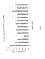
- Table 1 Fixed process parameters Parameter Value Unit Combined gas flow 20 slm Purge gas flow (N2) 70 slm Roller velocity 300 mm.s-1 Treatment cycles 1 Treatment width 303 mm Treatment length 80 mm Generator power 355 W Corona dose 65 W.min.m-2 Electrode substrate gap 1 mm Table 2 - Dopant gas and process variables Sample number Doping Gas Concentration / % Flow / slm Purge time / min 1 Untreated Celgard 2400 2 N2 - 20 2 3 C2H2 0.02 0.004 20 and 12 4 C2H2 0.5 0.1 2 5 CO2 0.2 0.04 2 6 CO2 20 4 2 7 N2O 0.2 0.04 2 8 N2O 2 4 2 9 NF3 0.2 0.04 2 10 NF3 2 4 2 11 NH3 0.2 0.04 2 12 NH3 2 4 2 13 SF6 0.2 0.04 2 14 SF6 2 0.4 2
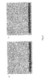
- Figure 3 illustrates SEM images showing a) sample 1 (comparative), untreated Celgard 2400, and b) sample 4, Celgard 2400 plasma treated with 0.5 % C 2 H 2 in N 2 .
- the images confirm that there is no change in the morphology of Celgard 2400 as a result of the plasma treatment. There is therefore expected to be no reduction in porosity as a result of pore filling.
- Negative Ion ToF-SIMs analysis of samples 1, 2 and 4 confirm the increased presence of electronegative species on the plasma treated separators, as shown in Table 3.
- Sample 4 displays particularly high levels of C-N species and gives rise to the lowest observed electrolyte contact angle.
- Table 3 - Species ratio data from Negative ToF SIMs O/C OH/C O/CH OH/CH CN/C Sample 1 tbc Sample 2 3.625 3.255 0.965 0.87 3.215 Sample 4 3.66 3.07 1.215 1.015 14.485
Landscapes
- Chemical & Material Sciences (AREA)
- General Chemical & Material Sciences (AREA)
- Chemical Kinetics & Catalysis (AREA)
- Electrochemistry (AREA)
- Life Sciences & Earth Sciences (AREA)
- Engineering & Computer Science (AREA)
- Manufacturing & Machinery (AREA)
- Sustainable Development (AREA)
- Sustainable Energy (AREA)
- Treatments Of Macromolecular Shaped Articles (AREA)
- Cell Separators (AREA)
Priority Applications (2)
| Application Number | Priority Date | Filing Date | Title |
|---|---|---|---|
| EP15153138.1A EP3051609A1 (de) | 2015-01-29 | 2015-01-29 | Plasmabehandelter Abscheider |
| PCT/EP2016/051880 WO2016120427A1 (en) | 2015-01-29 | 2016-01-29 | Plasma-treated separator |
Applications Claiming Priority (1)
| Application Number | Priority Date | Filing Date | Title |
|---|---|---|---|
| EP15153138.1A EP3051609A1 (de) | 2015-01-29 | 2015-01-29 | Plasmabehandelter Abscheider |
Publications (1)
| Publication Number | Publication Date |
|---|---|
| EP3051609A1 true EP3051609A1 (de) | 2016-08-03 |
Family
ID=52432717
Family Applications (1)
| Application Number | Title | Priority Date | Filing Date |
|---|---|---|---|
| EP15153138.1A Withdrawn EP3051609A1 (de) | 2015-01-29 | 2015-01-29 | Plasmabehandelter Abscheider |
Country Status (2)
| Country | Link |
|---|---|
| EP (1) | EP3051609A1 (de) |
| WO (1) | WO2016120427A1 (de) |
Citations (7)
| Publication number | Priority date | Publication date | Assignee | Title |
|---|---|---|---|---|
| WO2000034384A1 (en) | 1998-12-08 | 2000-06-15 | Lg Chemical Co. Ltd | Separator for secondary battery and porous film made of polyolefin blend and process for preparing the same |
| US20020170169A1 (en) * | 2001-05-21 | 2002-11-21 | Gonzalez Jose E. | System and method for multilayer fabrication of lithium polymer batteries and cells using surface treated separators |
| US6710098B1 (en) * | 1998-12-02 | 2004-03-23 | Lg Chemical Ltd. | Methods for reforming polymer surface for improved wettability |
| US20040213985A1 (en) * | 2000-06-23 | 2004-10-28 | Sang-Young Lee | Multi-component composite membrane and method for preparing the same |
| US20090130547A1 (en) | 2007-11-16 | 2009-05-21 | Young-Keun Lee | Microporous polyethylene film with improved strength, permeability and surface energy |
| WO2013058061A1 (ja) * | 2011-10-20 | 2013-04-25 | 東レバッテリーセパレータフィルム株式会社 | 多孔質膜の製造方法及びその多孔質膜、電池用セパレーター及び電池 |
| US20140050989A1 (en) | 2012-08-20 | 2014-02-20 | Samsung Sdi Co., Ltd. | Separator for rechargeable lithium battery and rechargeable lithium battery including same |
-
2015
- 2015-01-29 EP EP15153138.1A patent/EP3051609A1/de not_active Withdrawn
-
2016
- 2016-01-29 WO PCT/EP2016/051880 patent/WO2016120427A1/en not_active Ceased
Patent Citations (7)
| Publication number | Priority date | Publication date | Assignee | Title |
|---|---|---|---|---|
| US6710098B1 (en) * | 1998-12-02 | 2004-03-23 | Lg Chemical Ltd. | Methods for reforming polymer surface for improved wettability |
| WO2000034384A1 (en) | 1998-12-08 | 2000-06-15 | Lg Chemical Co. Ltd | Separator for secondary battery and porous film made of polyolefin blend and process for preparing the same |
| US20040213985A1 (en) * | 2000-06-23 | 2004-10-28 | Sang-Young Lee | Multi-component composite membrane and method for preparing the same |
| US20020170169A1 (en) * | 2001-05-21 | 2002-11-21 | Gonzalez Jose E. | System and method for multilayer fabrication of lithium polymer batteries and cells using surface treated separators |
| US20090130547A1 (en) | 2007-11-16 | 2009-05-21 | Young-Keun Lee | Microporous polyethylene film with improved strength, permeability and surface energy |
| WO2013058061A1 (ja) * | 2011-10-20 | 2013-04-25 | 東レバッテリーセパレータフィルム株式会社 | 多孔質膜の製造方法及びその多孔質膜、電池用セパレーター及び電池 |
| US20140050989A1 (en) | 2012-08-20 | 2014-02-20 | Samsung Sdi Co., Ltd. | Separator for rechargeable lithium battery and rechargeable lithium battery including same |
Also Published As
| Publication number | Publication date |
|---|---|
| WO2016120427A1 (en) | 2016-08-04 |
Similar Documents
| Publication | Publication Date | Title |
|---|---|---|
| EP2721193B1 (de) | Verfahren zur herstellung einer sperrschicht auf einem flexiblen substrat | |
| WO2022136699A1 (en) | Method for applying a protective layer to an alkali metal or alkali metal alloy surface, and article comprising such protective layer | |
| US20190386287A1 (en) | Separator for secondary cell having excellent heat resistance and shutdown properties | |
| US9627727B2 (en) | Lithium-air battery with cathode separated from free lithium ion | |
| EP2060599A1 (de) | Mikroporöse Polyethylenfolie mit verbesserter Festigkeit, Durchlässigkeit und Oberflächenenergie | |
| CN1170877C (zh) | 由聚烯烃掺混物制备的二次电池隔板和微孔膜及其制备方法 | |
| US6710098B1 (en) | Methods for reforming polymer surface for improved wettability | |
| US10446371B2 (en) | Boron implanting using a co-gas | |
| US20160351872A2 (en) | Separator | |
| EP2897197A1 (de) | Trennmembran für eine elektrochemische vorrichtung und herstellungsverfahren dafür | |
| JP6589440B2 (ja) | 蓄電池 | |
| EP3416211A1 (de) | Geätzte ionenspur poröse polymermembran als batterieseparator | |
| CN117813415A (zh) | 用于将保护层施用至金属或金属合金表面的方法和包括此保护层的制品 | |
| EP3051609A1 (de) | Plasmabehandelter Abscheider | |
| JP2006108047A (ja) | 電池の製造方法 | |
| WO2016120580A1 (en) | Separator | |
| KR102283543B1 (ko) | 반공유성 탄소-불소 관능기가 도입되어 안정성이 향상된 리튬이온배터리 음극재용 흑연의 제조방법 | |
| KR20010011032A (ko) | 2차전지용 금속 알루미늄과 구리 집전체의 처리 방법 | |
| JP7202526B2 (ja) | 非水電解液二次電池の製造方法 | |
| US20150318527A1 (en) | Plasma treatment of an electrochemical membrane | |
| JP3782716B2 (ja) | アルカリ電解質型二次電池用セパレーター、その製造方法及びそれを用いたアルカリ電解質型二次電池 | |
| KR20220023515A (ko) | 음극의 전리튬화 장치 및 음극의 전리튬화 방법 | |
| KR102219501B1 (ko) | 작업물 내로 프로세싱 종을 주입하는 방법 및 작업물 내로 도펀트를 주입하는 방법, 및 작업물을 프로세싱하기 위한 장치 | |
| EP4711491A1 (de) | Verfahren zum aufbringen einer schutzschicht auf eine metall- oder metalllegierungsoberfläche und artikel mit einer derartigen schutzschicht | |
| US20130120909A1 (en) | Lithium ion capacitor |
Legal Events
| Date | Code | Title | Description |
|---|---|---|---|
| PUAI | Public reference made under article 153(3) epc to a published international application that has entered the european phase |
Free format text: ORIGINAL CODE: 0009012 |
|
| 17P | Request for examination filed |
Effective date: 20150129 |
|
| AK | Designated contracting states |
Kind code of ref document: A1 Designated state(s): AL AT BE BG CH CY CZ DE DK EE ES FI FR GB GR HR HU IE IS IT LI LT LU LV MC MK MT NL NO PL PT RO RS SE SI SK SM TR |
|
| AX | Request for extension of the european patent |
Extension state: BA ME |
|
| 17Q | First examination report despatched |
Effective date: 20171026 |
|
| STAA | Information on the status of an ep patent application or granted ep patent |
Free format text: STATUS: THE APPLICATION IS DEEMED TO BE WITHDRAWN |
|
| 18D | Application deemed to be withdrawn |
Effective date: 20180306 |