EP3051500A1 - On-board device for an electronic fee collection system for vehicles - Google Patents
On-board device for an electronic fee collection system for vehicles Download PDFInfo
- Publication number
- EP3051500A1 EP3051500A1 EP15465501.3A EP15465501A EP3051500A1 EP 3051500 A1 EP3051500 A1 EP 3051500A1 EP 15465501 A EP15465501 A EP 15465501A EP 3051500 A1 EP3051500 A1 EP 3051500A1
- Authority
- EP
- European Patent Office
- Prior art keywords
- board device
- unit
- chip
- vehicle
- application processor
- Prior art date
- Legal status (The legal status is an assumption and is not a legal conclusion. Google has not performed a legal analysis and makes no representation as to the accuracy of the status listed.)
- Granted
Links
Images

Classifications
-
- G—PHYSICS
- G07—CHECKING-DEVICES
- G07B—TICKET-ISSUING APPARATUS; FARE-REGISTERING APPARATUS; FRANKING APPARATUS
- G07B15/00—Arrangements or apparatus for collecting fares, tolls or entrance fees at one or more control points
- G07B15/06—Arrangements for road pricing or congestion charging of vehicles or vehicle users, e.g. automatic toll systems
- G07B15/063—Arrangements for road pricing or congestion charging of vehicles or vehicle users, e.g. automatic toll systems using wireless information transmission between the vehicle and a fixed station
Definitions
- the present invention relates to an electronic fee collection system on toll roads. More particularly, the present invention relates to an on-board device for an electronic fee collection system and to a vehicle comprising such an on-board device.
- an on-board device for an electronic fee collection system for a vehicle comprising a positioning unit and an application processor, wherein the application processor and the positioning unit are integrated in one single chip as a system on chip.
- a vehicle in this context may be every vehicle that is subject to electronic fee collection when driving on a road or motorway on which toll is collected. This may include - but is not limited to - cars, busses, trucks, motorbikes, and tractors.
- on-board device means that the device is mounted to or is inside the respective vehicle, i.e. carried with it. This device can also be interoperable with existing vehicle systems.
- Electronic fee collection systems may affect drivers or others related to the vehicle on streets in countries which have decided to collect fees for driving on some or all streets with a vehicle.
- the on-board device comprises a positioning unit and an application processor.
- the positioning unit is a device which is designed to provide information about the vehicle position.
- the output of the positioning unit is information about the vehicle position, for instance an array of numbers describing geodetic coordinates, e.g. of the WGS-84 (World Geodetic System 1984), in a format that is readable by or compatible with the application processor.
- a main purpose of the application processor is the coordination of processes, which are executed in the processor or somewhere else in the device.
- the application processor executes its algorithms, collects data from peripheral units and commands tasks to peripheral units.
- Peripheral units can for example be the human-machine interface, a communication module, inertia sensors, temperature sensors, light sensors, or interfaces like a USB (universal serial bus) connection interface.
- Both, the application processor and the positioning unit are integrated in one single chip as a system on chip. This means that both, the application processor and the positioning unit, are merged together on one single board, and in addition, in one single chip. This single chip unifies the otherwise separated units, application processor and positioning unit. In other words, both, the application processor and the positioning unit, may not be distinguishable for an observer looking at the board and the chip.
- the functions of the application processor and the positioning unit are united in one piece of hardware, i.e. the one chip.
- the positioning unit may be in a standby mode most of the time, leaving all the computational power available to the application processor.
- the application processor and the positioning unit share hardware resources despite being generally physically separated on the system on chip. In all cases the implementation on one single chip may result in a system with a low footprint regarding costs, space and energy consumption in the vehicle.
- the on-board device further comprises a cryptographic unit, wherein the cryptographic unit is configured to encrypt and/or digitally sign data generated by the system on chip and wherein the cryptographic unit is connected to the system on chip.
- This cryptographic unit can be used to comply with privacy and data protection requirements. Information about the vehicle position is subject to privacy concerns and thus may be required to be protected sufficiently, e.g. against eavesdropping or fraud.
- the cryptographic unit in this embodiment is connected to the system on chip by respective interfaces and busses.
- the on-board device may be configured for data transmission between the cryptographic unit and the system on chip in both ways, i.e., back and forth, but it may also be configured for a one-way transmission from the cryptographic unit to the system on chip, e.g., by passing the signing key to the application processor.
- the on-board device further comprises a communication unit for transmitting data from the on-board device to, e.g., a backend office, wherein the communication unit is connected to the system on chip.
- the communication unit is capable of sending and receiving data, which data is, for instance, acquired by the application processor.
- a backend office may be placed at a company site and may include a server for data processing.
- the system on chip can be designed to be small, and a time critical data transmission may not necessary.
- the communication unit can also be designed to be minimalistic, i.e. small in its dimensions and with low hardware performance requirements. For instance, if a data packet is scheduled every 5 minutes to be sent from the communication unit, it may not even matter whether it is sent every 5 minutes or every 5 minutes and 20 seconds.
- the road tolling system can be configured to execute a less time critical workflow, e.g., by saving tasks into a queue of the system on chip and executing the tasks whenever it is appropriate. "Appropriate" in this context can mean that sufficient energy supply is available, or that a network connection with a sufficiently high signal-strength is available, or sufficient computing power can be provided to execute or coordinate a task.
- the communication unit is a GSM/GPRS module.
- GSM Global System for Mobile Communications
- GPRS General Packet Radio Service
- a GSM/GPRS module is a communication unit, that connects for example on the 2G or 3G cellular communication system for mobile communications.
- the data is position data to be sent to e.g. a backend office.
- the data stem for instance from the application processor.
- the position data is then sent to a backend office or the like.
- the application processor is configured to control peripheral devices.
- Peripheral devices can be the communication unit, the cryptographic unit, or other units that are configured as module to be connected to the on-board device.
- the application processor coordinates all tasks to be executed by the on-board device and the communication and commands between the peripheral devices and the application processor itself.
- Peripheral units can for example be the human-machine interface, a communication module, inertia sensors, temperature sensors, light sensors, or interface such as a USB (universal serial bus) connection interfaces.
- the application processor is running the software application which is managing all the peripherals.
- the positioning unit is a satellite navigation unit with a processor element for determining the vehicle position and coordinating processes within the satellite navigation unit and determining the vehicle position, wherein the positioning unit is connected to a satellite antenna for receiving satellite signals.
- a satellite navigation unit determines the position by means of signals emitted by satellites. Usually, determining one's location by satellite navigation is done by space based satellites, as for instance by NAVSTAR, GLONASS, GALILEO, IRNSS or the like. This includes the solving of equations, which can be done by a separate processor element in the satellite navigation unit or within shared resources with the application processor.
- the positioning unit is capable of determining the vehicle position without the help of devices other than the on-board device.
- the onboard-device is capable of determining the vehicle location without requiring any separate positioning system or navigation system.
- the on-board device is thus an independent system regarding determining the position of the vehicle. All elements necessary to determine the position of the vehicle, to which the on-board device is mounted or in which the on-board device is included, are contained in the on-board device, comprising an antenna for receiving signals emitted by satellites.
- the satellite antenna is an existing satellite antenna of the vehicle, which may also be configured to provide the satellite signals to a navigation system of the vehicle.
- the satellite antenna of the vehicle may be shared by the satellite navigation unit and, e.g., a navigation system, which is installed in the vehicle and independent from the on-board device.
- the positioning unit is a unit for acquiring the vehicle position.
- the position is determined by a vehicle navigation system, and corresponding position information is then transmitted to the positioning unit.
- the positioning unit can be provided with information about the vehicle position by, e.g., the navigation system of the vehicle. This requires an interface between the positioning unit and the existing system. With this embodiment, redundancy of systems for determining the vehicle position may be prevented.
- This embodiment contributes to the advantageous integration of the positioning unit and the application processor in one chip by allowing for the device to be smaller in size than in other embodiments. By sharing resources with existing systems, the size and energy consumption of the on-board device may be further reduced. This may also add to the required safety levels, as less weight and less space may contribute to a save integration in the vehicle of the on-board device.
- the on-board device comprises a cryptographic unit, wherein the cryptographic unit is configured to encrypt and/or digitally sign data generated by the system on chip and wherein the cryptographic unit is integrated in the system on chip.
- the cryptographic unit is part of the system on chip.
- the application processor, the positioning unit, and the cryptographic unit are integrated in one single chip as system on chip. For this reason, the cryptographic unit no longer belongs to the peripherals, but is part of the system on chip.
- Fig.1 shows an exemplary embodiment of an on-board device 100 for a vehicle, which comprises a positioning unit 111, an application processor 112, a satellite antenna 1117 and a cryptographic unit 113.
- the application processor 112, the positioning unit 111, and the cryptographic unit 113 are integrated in one single chip as a system on chip 110. Both, the positioning unit 111 and the application processor 112 may have interfaces to other units of the on-board device 100.
- One of these other units can be a communication unit 201 for transmitting data, wherein this unit is connected via an interface 114 to the system on a chip 110, for example to the application processor 112.
- the cryptopraphic unit 113' however may also be integrated in an external chip, i.e. it would not be integrated in the system on chip 110. In this case, the cryptopraphic unit 113' is connected to the system on chip rather than a cryptopraphic unit 113, which is integrated in the system on chip.
- a satellite antenna 1117 is integrated in the positioning unit 111 for determining the vehicle position inside the on-board device 100.
- the satellite antenna 1117' may also be connected to the system on chip 110, as opposed to be integrated in the system on chip 110.
- the communication unit 201 communicates with a backend office 800.
- the backend office is a central company site with a server, which serves as data logger for example.
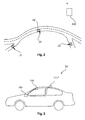
- Fig. 2 shows a route of a vehicle, on which positions 21, 22, 23 are located.
- the positions correspond to a driving time of 5 minutes between each position.
- the time span of 5 minutes may be chosen by the on-board device 100.
- every 5 minutes a determination of the vehicle position is to be conducted by the on-bard device 100.
- the position data is to be transmitted via the communication unit 201, e.g. in the GSM network, to a backend office 800.
- Fig. 3 shows a vehicle 50, with an onboard device 100, a satellite antenna 1117', and a car navigation system 300.
- the vehicle 50 as shown in this example is a passenger car. As many passenger cars it features a navigation system 300 which receives signals from a satellite positioning network.
- the navigation system 300 is connected to or comprises the satellite antenna 1117', by which satellite signals for the navigation system 300 are received.
- the navigation system 300 is generally capable of determining a vehicle position when connected to the satellite antenna 1117'.
- the navigation system 300 may have one or more interfaces for transmission of the position in WGS-84 compliant coordinates, e.g. Longitude and Latitude, while the altitude is discarded.
- the positioning unit 111 receives the position information and ensures the right format for the application processor 112. For instance, every 5 minutes the system on chip 110 requests the current position from the navigation system 300 or listens at the respective port for the information to be sent, which information may be periodically sent by the navigation system 300.
- the positioning unit 111, integrated in the system on chip, 110 can be designed such that it consumes very little space in the on-board device, thus allowing for the on-board device itself being of small size.
Landscapes
- Engineering & Computer Science (AREA)
- Computer Networks & Wireless Communication (AREA)
- Business, Economics & Management (AREA)
- Finance (AREA)
- Physics & Mathematics (AREA)
- General Physics & Mathematics (AREA)
- Devices For Checking Fares Or Tickets At Control Points (AREA)
- Traffic Control Systems (AREA)
Abstract
Description
- The present invention relates to an electronic fee collection system on toll roads. More particularly, the present invention relates to an on-board device for an electronic fee collection system and to a vehicle comprising such an on-board device.
- In countries where toll roads account for a significant amount of the road system, electronic road tolling systems are widely used. The integration of devices in vehicles may be subject to safety concerns and acceptance of vehicle drivers may be crucial. There are several kinds of systems available. Some use satellite based navigation, others are limited in data transmission range by near field communication or comparable technologies and communicate directly with systems mounted nearby the road, and are thus part of the infrastructure. In all applications of automated toll collecting, data security and privacy may play a major role for users.
- It may be desirable to have a cost-effective, small, and simple device onboard a vehicle for an electronic fee collection system.
- The object of the present invention is solved by the subject-matter of the independent claims, wherein further embodiments are incorporated in the dependent claims and the following description of aspects and embodiments.
- According to an aspect of the invention, an on-board device for an electronic fee collection system for a vehicle is provided, comprising a positioning unit and an application processor, wherein the application processor and the positioning unit are integrated in one single chip as a system on chip.
- A vehicle in this context may be every vehicle that is subject to electronic fee collection when driving on a road or motorway on which toll is collected. This may include - but is not limited to - cars, busses, trucks, motorbikes, and tractors.
- The expression "on-board device" means that the device is mounted to or is inside the respective vehicle, i.e. carried with it. This device can also be interoperable with existing vehicle systems.
- Electronic fee collection systems may affect drivers or others related to the vehicle on streets in countries which have decided to collect fees for driving on some or all streets with a vehicle.
- The on-board device comprises a positioning unit and an application processor. The positioning unit is a device which is designed to provide information about the vehicle position. The output of the positioning unit is information about the vehicle position, for instance an array of numbers describing geodetic coordinates, e.g. of the WGS-84 (World Geodetic System 1984), in a format that is readable by or compatible with the application processor. A main purpose of the application processor is the coordination of processes, which are executed in the processor or somewhere else in the device. The application processor executes its algorithms, collects data from peripheral units and commands tasks to peripheral units. Peripheral units can for example be the human-machine interface, a communication module, inertia sensors, temperature sensors, light sensors, or interfaces like a USB (universal serial bus) connection interface.
- Both, the application processor and the positioning unit are integrated in one single chip as a system on chip. This means that both, the application processor and the positioning unit, are merged together on one single board, and in addition, in one single chip. This single chip unifies the otherwise separated units, application processor and positioning unit. In other words, both, the application processor and the positioning unit, may not be distinguishable for an observer looking at the board and the chip. The functions of the application processor and the positioning unit are united in one piece of hardware, i.e. the one chip.
- Combining the application processor and the positioning unit in one chip can have several benefits:
- First, the costs for hardware may be lowered. By unifying two subsystems in one single entity, interfaces rather reduce to software interfaces than being physically implemented in two separate units. This may be achieved by replacing two electronic boards or two processors by a single one, whereby the single board or the single processor can be of higher performance.
- Second, the system on chip may also require less space in the device and therefore the device may be designed smaller, taking less space in the vehicle. As the two units are united and integrated in one chip, the device may be less energy consuming. In addition, as an electronic toll system is not critical regarding the acquisition rate and transmission rate of position information, the system may have low requirements regarding hardware performance. If, for example, the system on chip is realized in the Von Neumann architecture, for instance the "Memory Unit" of the processor can be shared by the two logical units, i.e. the application processor and the positioning unit. Also other elements can be shared, for example the ALU (arithmetic logic unit).
- Assuming that information about the vehicle position is required with a specific minimum rate, i.e., position measurements per time or position measurements per distance, e.g. every 5 minutes or every 5 kilometers, the positioning unit may be in a standby mode most of the time, leaving all the computational power available to the application processor.
- It may also be provided that the application processor and the positioning unit share hardware resources despite being generally physically separated on the system on chip. In all cases the implementation on one single chip may result in a system with a low footprint regarding costs, space and energy consumption in the vehicle.
- According to an exemplary embodiment of the present invention, the on-board device further comprises a cryptographic unit, wherein the cryptographic unit is configured to encrypt and/or digitally sign data generated by the system on chip and wherein the cryptographic unit is connected to the system on chip. This cryptographic unit can be used to comply with privacy and data protection requirements. Information about the vehicle position is subject to privacy concerns and thus may be required to be protected sufficiently, e.g. against eavesdropping or fraud. The cryptographic unit in this embodiment is connected to the system on chip by respective interfaces and busses. The on-board device may be configured for data transmission between the cryptographic unit and the system on chip in both ways, i.e., back and forth, but it may also be configured for a one-way transmission from the cryptographic unit to the system on chip, e.g., by passing the signing key to the application processor.
- According to another exemplary embodiment of the present invention, the on-board device further comprises a communication unit for transmitting data from the on-board device to, e.g., a backend office, wherein the communication unit is connected to the system on chip. The communication unit is capable of sending and receiving data, which data is, for instance, acquired by the application processor. A backend office may be placed at a company site and may include a server for data processing.
- With the work flow of acquiring or transmitting data required to be repeated in relatively low frequency, for instance every 1 to 10 minutes, or every 1 to 10 kilometers, the system on chip can be designed to be small, and a time critical data transmission may not necessary. Hence, the communication unit can also be designed to be minimalistic, i.e. small in its dimensions and with low hardware performance requirements. For instance, if a data packet is scheduled every 5 minutes to be sent from the communication unit, it may not even matter whether it is sent every 5 minutes or every 5 minutes and 20 seconds. The road tolling system can be configured to execute a less time critical workflow, e.g., by saving tasks into a queue of the system on chip and executing the tasks whenever it is appropriate. "Appropriate" in this context can mean that sufficient energy supply is available, or that a network connection with a sufficiently high signal-strength is available, or sufficient computing power can be provided to execute or coordinate a task.
- According to another exemplary embodiment of the present invention, the communication unit is a GSM/GPRS module. (GSM: "Global System for Mobile Communications"; GPRS: "General Packet Radio Service") A GSM/GPRS module is a communication unit, that connects for example on the 2G or 3G cellular communication system for mobile communications.
- According to another exemplary embodiment of the present invention, the data is position data to be sent to e.g. a backend office. The data stem for instance from the application processor. The position data is then sent to a backend office or the like.
- According to another exemplary embodiment of the present invention, the application processor is configured to control peripheral devices. Peripheral devices can be the communication unit, the cryptographic unit, or other units that are configured as module to be connected to the on-board device. In this sense, the application processor coordinates all tasks to be executed by the on-board device and the communication and commands between the peripheral devices and the application processor itself. Peripheral units can for example be the human-machine interface, a communication module, inertia sensors, temperature sensors, light sensors, or interface such as a USB (universal serial bus) connection interfaces. In other words, the application processor is running the software application which is managing all the peripherals.
- According to another exemplary embodiment of the present invention, the positioning unit is a satellite navigation unit with a processor element for determining the vehicle position and coordinating processes within the satellite navigation unit and determining the vehicle position, wherein the positioning unit is connected to a satellite antenna for receiving satellite signals. A satellite navigation unit determines the position by means of signals emitted by satellites. Usually, determining one's location by satellite navigation is done by space based satellites, as for instance by NAVSTAR, GLONASS, GALILEO, IRNSS or the like. This includes the solving of equations, which can be done by a separate processor element in the satellite navigation unit or within shared resources with the application processor. According to this embodiment, the positioning unit is capable of determining the vehicle position without the help of devices other than the on-board device. This means, the onboard-device is capable of determining the vehicle location without requiring any separate positioning system or navigation system. The on-board device is thus an independent system regarding determining the position of the vehicle. All elements necessary to determine the position of the vehicle, to which the on-board device is mounted or in which the on-board device is included, are contained in the on-board device, comprising an antenna for receiving signals emitted by satellites.
- According to another exemplary embodiment of the present invention, the satellite antenna is an existing satellite antenna of the vehicle, which may also be configured to provide the satellite signals to a navigation system of the vehicle. In other words, the satellite antenna of the vehicle may be shared by the satellite navigation unit and, e.g., a navigation system, which is installed in the vehicle and independent from the on-board device.
- According to another exemplary embodiment of the present invention, the positioning unit is a unit for acquiring the vehicle position. The position is determined by a vehicle navigation system, and corresponding position information is then transmitted to the positioning unit. In other words, the positioning unit can be provided with information about the vehicle position by, e.g., the navigation system of the vehicle. This requires an interface between the positioning unit and the existing system. With this embodiment, redundancy of systems for determining the vehicle position may be prevented.
- This embodiment contributes to the advantageous integration of the positioning unit and the application processor in one chip by allowing for the device to be smaller in size than in other embodiments. By sharing resources with existing systems, the size and energy consumption of the on-board device may be further reduced. This may also add to the required safety levels, as less weight and less space may contribute to a save integration in the vehicle of the on-board device.
- According to another exemplary embodiment of the present invention, the on-board device comprises a cryptographic unit, wherein the cryptographic unit is configured to encrypt and/or digitally sign data generated by the system on chip and wherein the cryptographic unit is integrated in the system on chip. This means that the cryptographic unit is part of the system on chip. In other words, the application processor, the positioning unit, and the cryptographic unit are integrated in one single chip as system on chip. For this reason, the cryptographic unit no longer belongs to the peripherals, but is part of the system on chip.
- These and other aspects of the invention will become apparent from and elucidated with reference to the embodiments hereinafter. Exemplary embodiments of the present invention will now be described in the following, with reference to the following drawings.
-
Fig. 1 shows a topology of the on-board device according to an exemplary embodiment of the present invention. -
Fig. 2 shows a route of a vehicle with points of data capturing and data transmission according to an exemplary embodiment of the present invention. -
Fig. 3 shows a vehicle according to an exemplary embodiment of the present invention comprising an on-board device. - The illustration in the drawings is schematically. In different drawings, similar or identical elements are provided with the same reference numerals.
- The following detailed description is merely exemplary in nature and is not intended to limit application and uses. Furthermore, there is no intention to be bound by any theory presented in the preceding background or summary or the following detailed description.
-
Fig.1 shows an exemplary embodiment of an on-board device 100 for a vehicle, which comprises apositioning unit 111, anapplication processor 112, asatellite antenna 1117 and acryptographic unit 113. Theapplication processor 112, thepositioning unit 111, and thecryptographic unit 113 are integrated in one single chip as a system onchip 110. Both, thepositioning unit 111 and theapplication processor 112 may have interfaces to other units of the on-board device 100. One of these other units can be acommunication unit 201 for transmitting data, wherein this unit is connected via aninterface 114 to the system on achip 110, for example to theapplication processor 112. The cryptopraphic unit 113' however may also be integrated in an external chip, i.e. it would not be integrated in the system onchip 110. In this case, the cryptopraphic unit 113' is connected to the system on chip rather than acryptopraphic unit 113, which is integrated in the system on chip. - In this example, a
satellite antenna 1117 is integrated in thepositioning unit 111 for determining the vehicle position inside the on-board device 100. However, the satellite antenna 1117' may also be connected to the system onchip 110, as opposed to be integrated in the system onchip 110. - The
communication unit 201 communicates with abackend office 800. In this example, the backend office is a central company site with a server, which serves as data logger for example. -
Fig. 2 shows a route of a vehicle, on which positions 21, 22, 23 are located. In this example, the positions correspond to a driving time of 5 minutes between each position. The time span of 5 minutes may be chosen by the on-board device 100. In this manner, every 5 minutes a determination of the vehicle position is to be conducted by the on-bard device 100. Also, as scheduled process after the determination of the vehicle position, after every 5 minutes during driving, the position data is to be transmitted via thecommunication unit 201, e.g. in the GSM network, to abackend office 800. -
Fig. 3 shows avehicle 50, with anonboard device 100, a satellite antenna 1117', and acar navigation system 300. Thevehicle 50 as shown in this example is a passenger car. As many passenger cars it features anavigation system 300 which receives signals from a satellite positioning network. - The
navigation system 300 is connected to or comprises the satellite antenna 1117', by which satellite signals for thenavigation system 300 are received. In this example, thenavigation system 300 is generally capable of determining a vehicle position when connected to the satellite antenna 1117'. Thenavigation system 300 may have one or more interfaces for transmission of the position in WGS-84 compliant coordinates, e.g. Longitude and Latitude, while the altitude is discarded. - With the
navigation system 300 being connected to the on-board device 100 for electronic fee collection, thepositioning unit 111 receives the position information and ensures the right format for theapplication processor 112. For instance, every 5 minutes the system onchip 110 requests the current position from thenavigation system 300 or listens at the respective port for the information to be sent, which information may be periodically sent by thenavigation system 300. Thus, thepositioning unit 111, integrated in the system on chip, 110 can be designed such that it consumes very little space in the on-board device, thus allowing for the on-board device itself being of small size.
Claims (12)
- On-board device (100) for an electronic fee collection system for a vehicle (50), comprising:a positioning unit (111) and an application processor (112);wherein the application processor (112) and the positioning unit (111) are integrated in one single chip as a system on chip (110).
- On-board device (100) according to any one of the preceding claims, further comprising:a communication unit (201) for transmitting data from the on-board device (100) to a backend office (800) of the electronic fee collection system;wherein the communication unit (201) is connected to the system on chip (110).
- On-board device (100) according to claim 2,
wherein the communication unit (201) is a GSM/GPRS module. - On-board device (100) according to any one of claims 2 to 3,
wherein the data is position data to be sent to a backend office (800). - On-board device (100) according to any one of the preceding claims,
wherein the application processor (112) is configured to control peripheral devices. - On-board device (100) according to any one of the preceding claims;
wherein the positioning unit (111) is a satellite navigation unit; and
wherein the positioning unit (111) is connected to a satellite antenna (1117') for receiving satellite signals. - On-board device (100) according to claim 6,
wherein the satellite antenna (1117) is integrated in the system on chip (110). - On-board device (100) according to claim 6,
wherein the satellite antenna (1117') is a satellite antenna of the vehicle. - On-board device (100) according to any one of the claims 1 to 5,
wherein the positioning unit (111) is a unit for acquiring the vehicle position, which position is determined by a vehicle navigation system providing navigational assistance to the driver. - On-board device (100) according to one of the claims 1 to 9, further comprising:a cryptographic unit (113');wherein the cryptographic unit (113') is configured to encrypt and/or digitally sign data generated by the system on chip (110); andwherein the cryptographic unit (113') is connected to the system on chip (110).
- On-board device (100) according to one of the claims 1 to 9, further comprising:a cryptographic unit (113), wherein the cryptographic unit (113) is configured to encrypt and/or digitally sign data generated by the system on chip (110) andwherein the cryptographic unit (113) is integrated in the system on chip (110).
- Vehicle (50) comprising an on-board device according to one of the preceding claims.
Priority Applications (1)
| Application Number | Priority Date | Filing Date | Title |
|---|---|---|---|
| EP15465501.3A EP3051500B1 (en) | 2015-01-29 | 2015-01-29 | On-board device for an electronic fee collection system for vehicles |
Applications Claiming Priority (1)
| Application Number | Priority Date | Filing Date | Title |
|---|---|---|---|
| EP15465501.3A EP3051500B1 (en) | 2015-01-29 | 2015-01-29 | On-board device for an electronic fee collection system for vehicles |
Publications (2)
| Publication Number | Publication Date |
|---|---|
| EP3051500A1 true EP3051500A1 (en) | 2016-08-03 |
| EP3051500B1 EP3051500B1 (en) | 2021-05-19 |
Family
ID=52824211
Family Applications (1)
| Application Number | Title | Priority Date | Filing Date |
|---|---|---|---|
| EP15465501.3A Active EP3051500B1 (en) | 2015-01-29 | 2015-01-29 | On-board device for an electronic fee collection system for vehicles |
Country Status (1)
| Country | Link |
|---|---|
| EP (1) | EP3051500B1 (en) |
Citations (4)
| Publication number | Priority date | Publication date | Assignee | Title |
|---|---|---|---|---|
| US20090254270A1 (en) * | 2008-04-02 | 2009-10-08 | O2Micro, Inc. | System and method for tracking a path of a vehicle |
| CN102903150A (en) * | 2011-07-29 | 2013-01-30 | 深圳光启高等理工研究院 | Toll collection system, toll collection method and bus utilizing toll collection system |
| US20130090991A1 (en) * | 2011-10-05 | 2013-04-11 | Verizon Patent And Licensing Inc. | Apparatus, system, and method for toll payment via smart phone |
| US20130317741A1 (en) * | 2012-05-23 | 2013-11-28 | Vectornav Technologies, Llc | System on a chip inertial navigation system |
-
2015
- 2015-01-29 EP EP15465501.3A patent/EP3051500B1/en active Active
Patent Citations (4)
| Publication number | Priority date | Publication date | Assignee | Title |
|---|---|---|---|---|
| US20090254270A1 (en) * | 2008-04-02 | 2009-10-08 | O2Micro, Inc. | System and method for tracking a path of a vehicle |
| CN102903150A (en) * | 2011-07-29 | 2013-01-30 | 深圳光启高等理工研究院 | Toll collection system, toll collection method and bus utilizing toll collection system |
| US20130090991A1 (en) * | 2011-10-05 | 2013-04-11 | Verizon Patent And Licensing Inc. | Apparatus, system, and method for toll payment via smart phone |
| US20130317741A1 (en) * | 2012-05-23 | 2013-11-28 | Vectornav Technologies, Llc | System on a chip inertial navigation system |
Non-Patent Citations (1)
| Title |
|---|
| NXP: "NXP and Siemens develop GPS/GSM-based toll system for private vehicles", 6 May 2008 (2008-05-06), Eindhoven, The Netherlands, XP002741885, Retrieved from the Internet <URL:http://www.nxp.com/news/press-releases/2008/05/nxp-and-siemens-develop-gps-gsm-based-toll-system-for-private-vehicles.html> [retrieved on 20150707] * |
Also Published As
| Publication number | Publication date |
|---|---|
| EP3051500B1 (en) | 2021-05-19 |
Similar Documents
| Publication | Publication Date | Title |
|---|---|---|
| US11887406B2 (en) | Vehicle-based electronic toll system with interface to vehicle display | |
| CN109307877A (en) | High-precision vehicle positioning system and high-precision vehicle positioning method | |
| JP2013101013A (en) | Position orientation device, on-vehicle unit, position orientation method, position orientation program, driving support method, driving support program, road accounting method, road accounting program, position orientation system, driving support system and road accounting system | |
| CN101950027A (en) | Navigational satellite signal receiving module and information processing method applied to same | |
| WO2015002219A1 (en) | Vehicle-mounted device and spoofing detection method | |
| CN103149572A (en) | GNSS architecture | |
| KR102806901B1 (en) | Method for image processing based on message and electronic device implementing the same | |
| CN115004271A (en) | Method for embedding protected vehicle identifier information in cellular vehicle-to-all (C-V2X) messages | |
| US20160313135A1 (en) | Method, portable terminal, in-vehicle terminal and system for vehicle positioning | |
| CN110751808B (en) | Information processing method and device, electronic equipment and storage medium | |
| JP2019008709A (en) | Vehicle, information processing system, information processing device, and data structure | |
| WO2016145886A1 (en) | On board unit | |
| CN111947677A (en) | Shared vehicle positioning method and device | |
| EP2752642B1 (en) | Tachograph | |
| CN103091690A (en) | Traffic Violation Cooperative Management Positioning System Based on NFC and GPS | |
| EP3046090A1 (en) | An apparatus, a method, and a computer program for assisting a driver | |
| EP3051500B1 (en) | On-board device for an electronic fee collection system for vehicles | |
| CN110832563B (en) | Information communication device and location management system | |
| JP6946660B2 (en) | Positioning device | |
| EP3972227B1 (en) | Method for driving control, device and system | |
| CN202998481U (en) | Traffic Violation Cooperative Management Positioning System Based on NFC and GPS | |
| JP2019096153A (en) | On-vehicle device, the same road traveling determination method, and the same road traveling determination program | |
| Shah et al. | Decentralized fleet monitoring and tracking system | |
| JP4305417B2 (en) | Probe information collection system and FCD in-vehicle device | |
| CZ200696A3 (en) | Device for determination of position |
Legal Events
| Date | Code | Title | Description |
|---|---|---|---|
| PUAI | Public reference made under article 153(3) epc to a published international application that has entered the european phase |
Free format text: ORIGINAL CODE: 0009012 |
|
| AK | Designated contracting states |
Kind code of ref document: A1 Designated state(s): AL AT BE BG CH CY CZ DE DK EE ES FI FR GB GR HR HU IE IS IT LI LT LU LV MC MK MT NL NO PL PT RO RS SE SI SK SM TR |
|
| AX | Request for extension of the european patent |
Extension state: BA ME |
|
| STAA | Information on the status of an ep patent application or granted ep patent |
Free format text: STATUS: REQUEST FOR EXAMINATION WAS MADE |
|
| 17P | Request for examination filed |
Effective date: 20170203 |
|
| RBV | Designated contracting states (corrected) |
Designated state(s): AL AT BE BG CH CY CZ DE DK EE ES FI FR GB GR HR HU IE IS IT LI LT LU LV MC MK MT NL NO PL PT RO RS SE SI SK SM TR |
|
| RAP1 | Party data changed (applicant data changed or rights of an application transferred) |
Owner name: CONTINENTAL AUTOMOTIVE GMBH |
|
| GRAP | Despatch of communication of intention to grant a patent |
Free format text: ORIGINAL CODE: EPIDOSNIGR1 |
|
| STAA | Information on the status of an ep patent application or granted ep patent |
Free format text: STATUS: GRANT OF PATENT IS INTENDED |
|
| INTG | Intention to grant announced |
Effective date: 20210122 |
|
| GRAS | Grant fee paid |
Free format text: ORIGINAL CODE: EPIDOSNIGR3 |
|
| GRAA | (expected) grant |
Free format text: ORIGINAL CODE: 0009210 |
|
| STAA | Information on the status of an ep patent application or granted ep patent |
Free format text: STATUS: THE PATENT HAS BEEN GRANTED |
|
| AK | Designated contracting states |
Kind code of ref document: B1 Designated state(s): AL AT BE BG CH CY CZ DE DK EE ES FI FR GB GR HR HU IE IS IT LI LT LU LV MC MK MT NL NO PL PT RO RS SE SI SK SM TR |
|
| REG | Reference to a national code |
Ref country code: GB Ref legal event code: FG4D |
|
| REG | Reference to a national code |
Ref country code: CH Ref legal event code: EP |
|
| REG | Reference to a national code |
Ref country code: DE Ref legal event code: R096 Ref document number: 602015069388 Country of ref document: DE |
|
| REG | Reference to a national code |
Ref country code: AT Ref legal event code: REF Ref document number: 1394717 Country of ref document: AT Kind code of ref document: T Effective date: 20210615 |
|
| REG | Reference to a national code |
Ref country code: IE Ref legal event code: FG4D |
|
| REG | Reference to a national code |
Ref country code: LT Ref legal event code: MG9D |
|
| REG | Reference to a national code |
Ref country code: AT Ref legal event code: MK05 Ref document number: 1394717 Country of ref document: AT Kind code of ref document: T Effective date: 20210519 |
|
| REG | Reference to a national code |
Ref country code: NL Ref legal event code: MP Effective date: 20210519 |
|
| PG25 | Lapsed in a contracting state [announced via postgrant information from national office to epo] |
Ref country code: BG Free format text: LAPSE BECAUSE OF FAILURE TO SUBMIT A TRANSLATION OF THE DESCRIPTION OR TO PAY THE FEE WITHIN THE PRESCRIBED TIME-LIMIT Effective date: 20210819 Ref country code: AT Free format text: LAPSE BECAUSE OF FAILURE TO SUBMIT A TRANSLATION OF THE DESCRIPTION OR TO PAY THE FEE WITHIN THE PRESCRIBED TIME-LIMIT Effective date: 20210519 Ref country code: HR Free format text: LAPSE BECAUSE OF FAILURE TO SUBMIT A TRANSLATION OF THE DESCRIPTION OR TO PAY THE FEE WITHIN THE PRESCRIBED TIME-LIMIT Effective date: 20210519 Ref country code: FI Free format text: LAPSE BECAUSE OF FAILURE TO SUBMIT A TRANSLATION OF THE DESCRIPTION OR TO PAY THE FEE WITHIN THE PRESCRIBED TIME-LIMIT Effective date: 20210519 Ref country code: LT Free format text: LAPSE BECAUSE OF FAILURE TO SUBMIT A TRANSLATION OF THE DESCRIPTION OR TO PAY THE FEE WITHIN THE PRESCRIBED TIME-LIMIT Effective date: 20210519 |
|
| PG25 | Lapsed in a contracting state [announced via postgrant information from national office to epo] |
Ref country code: LV Free format text: LAPSE BECAUSE OF FAILURE TO SUBMIT A TRANSLATION OF THE DESCRIPTION OR TO PAY THE FEE WITHIN THE PRESCRIBED TIME-LIMIT Effective date: 20210519 Ref country code: IS Free format text: LAPSE BECAUSE OF FAILURE TO SUBMIT A TRANSLATION OF THE DESCRIPTION OR TO PAY THE FEE WITHIN THE PRESCRIBED TIME-LIMIT Effective date: 20210919 Ref country code: GR Free format text: LAPSE BECAUSE OF FAILURE TO SUBMIT A TRANSLATION OF THE DESCRIPTION OR TO PAY THE FEE WITHIN THE PRESCRIBED TIME-LIMIT Effective date: 20210820 Ref country code: RS Free format text: LAPSE BECAUSE OF FAILURE TO SUBMIT A TRANSLATION OF THE DESCRIPTION OR TO PAY THE FEE WITHIN THE PRESCRIBED TIME-LIMIT Effective date: 20210519 Ref country code: SE Free format text: LAPSE BECAUSE OF FAILURE TO SUBMIT A TRANSLATION OF THE DESCRIPTION OR TO PAY THE FEE WITHIN THE PRESCRIBED TIME-LIMIT Effective date: 20210519 Ref country code: PT Free format text: LAPSE BECAUSE OF FAILURE TO SUBMIT A TRANSLATION OF THE DESCRIPTION OR TO PAY THE FEE WITHIN THE PRESCRIBED TIME-LIMIT Effective date: 20210920 Ref country code: NO Free format text: LAPSE BECAUSE OF FAILURE TO SUBMIT A TRANSLATION OF THE DESCRIPTION OR TO PAY THE FEE WITHIN THE PRESCRIBED TIME-LIMIT Effective date: 20210819 Ref country code: PL Free format text: LAPSE BECAUSE OF FAILURE TO SUBMIT A TRANSLATION OF THE DESCRIPTION OR TO PAY THE FEE WITHIN THE PRESCRIBED TIME-LIMIT Effective date: 20210519 Ref country code: ES Free format text: LAPSE BECAUSE OF FAILURE TO SUBMIT A TRANSLATION OF THE DESCRIPTION OR TO PAY THE FEE WITHIN THE PRESCRIBED TIME-LIMIT Effective date: 20210519 |
|
| PG25 | Lapsed in a contracting state [announced via postgrant information from national office to epo] |
Ref country code: NL Free format text: LAPSE BECAUSE OF FAILURE TO SUBMIT A TRANSLATION OF THE DESCRIPTION OR TO PAY THE FEE WITHIN THE PRESCRIBED TIME-LIMIT Effective date: 20210519 |
|
| PG25 | Lapsed in a contracting state [announced via postgrant information from national office to epo] |
Ref country code: RO Free format text: LAPSE BECAUSE OF FAILURE TO SUBMIT A TRANSLATION OF THE DESCRIPTION OR TO PAY THE FEE WITHIN THE PRESCRIBED TIME-LIMIT Effective date: 20210519 Ref country code: SM Free format text: LAPSE BECAUSE OF FAILURE TO SUBMIT A TRANSLATION OF THE DESCRIPTION OR TO PAY THE FEE WITHIN THE PRESCRIBED TIME-LIMIT Effective date: 20210519 Ref country code: SK Free format text: LAPSE BECAUSE OF FAILURE TO SUBMIT A TRANSLATION OF THE DESCRIPTION OR TO PAY THE FEE WITHIN THE PRESCRIBED TIME-LIMIT Effective date: 20210519 Ref country code: EE Free format text: LAPSE BECAUSE OF FAILURE TO SUBMIT A TRANSLATION OF THE DESCRIPTION OR TO PAY THE FEE WITHIN THE PRESCRIBED TIME-LIMIT Effective date: 20210519 Ref country code: CZ Free format text: LAPSE BECAUSE OF FAILURE TO SUBMIT A TRANSLATION OF THE DESCRIPTION OR TO PAY THE FEE WITHIN THE PRESCRIBED TIME-LIMIT Effective date: 20210519 Ref country code: DK Free format text: LAPSE BECAUSE OF FAILURE TO SUBMIT A TRANSLATION OF THE DESCRIPTION OR TO PAY THE FEE WITHIN THE PRESCRIBED TIME-LIMIT Effective date: 20210519 |
|
| REG | Reference to a national code |
Ref country code: DE Ref legal event code: R097 Ref document number: 602015069388 Country of ref document: DE |
|
| PLBE | No opposition filed within time limit |
Free format text: ORIGINAL CODE: 0009261 |
|
| STAA | Information on the status of an ep patent application or granted ep patent |
Free format text: STATUS: NO OPPOSITION FILED WITHIN TIME LIMIT |
|
| 26N | No opposition filed |
Effective date: 20220222 |
|
| PG25 | Lapsed in a contracting state [announced via postgrant information from national office to epo] |
Ref country code: IS Free format text: LAPSE BECAUSE OF FAILURE TO SUBMIT A TRANSLATION OF THE DESCRIPTION OR TO PAY THE FEE WITHIN THE PRESCRIBED TIME-LIMIT Effective date: 20210919 Ref country code: AL Free format text: LAPSE BECAUSE OF FAILURE TO SUBMIT A TRANSLATION OF THE DESCRIPTION OR TO PAY THE FEE WITHIN THE PRESCRIBED TIME-LIMIT Effective date: 20210519 |
|
| REG | Reference to a national code |
Ref country code: DE Ref legal event code: R081 Ref document number: 602015069388 Country of ref document: DE Owner name: CONTINENTAL AUTOMOTIVE TECHNOLOGIES GMBH, DE Free format text: FORMER OWNER: CONTINENTAL AUTOMOTIVE GMBH, 30165 HANNOVER, DE Ref country code: DE Ref legal event code: R081 Ref document number: 602015069388 Country of ref document: DE Owner name: AUMOVIO GERMANY GMBH, DE Free format text: FORMER OWNER: CONTINENTAL AUTOMOTIVE GMBH, 30165 HANNOVER, DE |
|
| PG25 | Lapsed in a contracting state [announced via postgrant information from national office to epo] |
Ref country code: IT Free format text: LAPSE BECAUSE OF FAILURE TO SUBMIT A TRANSLATION OF THE DESCRIPTION OR TO PAY THE FEE WITHIN THE PRESCRIBED TIME-LIMIT Effective date: 20210519 |
|
| PG25 | Lapsed in a contracting state [announced via postgrant information from national office to epo] |
Ref country code: MC Free format text: LAPSE BECAUSE OF FAILURE TO SUBMIT A TRANSLATION OF THE DESCRIPTION OR TO PAY THE FEE WITHIN THE PRESCRIBED TIME-LIMIT Effective date: 20210519 |
|
| REG | Reference to a national code |
Ref country code: CH Ref legal event code: PL |
|
| GBPC | Gb: european patent ceased through non-payment of renewal fee |
Effective date: 20220129 |
|
| REG | Reference to a national code |
Ref country code: BE Ref legal event code: MM Effective date: 20220131 |
|
| PG25 | Lapsed in a contracting state [announced via postgrant information from national office to epo] |
Ref country code: LU Free format text: LAPSE BECAUSE OF NON-PAYMENT OF DUE FEES Effective date: 20220129 Ref country code: GB Free format text: LAPSE BECAUSE OF NON-PAYMENT OF DUE FEES Effective date: 20220129 |
|
| PG25 | Lapsed in a contracting state [announced via postgrant information from national office to epo] |
Ref country code: BE Free format text: LAPSE BECAUSE OF NON-PAYMENT OF DUE FEES Effective date: 20220131 |
|
| PG25 | Lapsed in a contracting state [announced via postgrant information from national office to epo] |
Ref country code: LI Free format text: LAPSE BECAUSE OF NON-PAYMENT OF DUE FEES Effective date: 20220131 Ref country code: CH Free format text: LAPSE BECAUSE OF NON-PAYMENT OF DUE FEES Effective date: 20220131 |
|
| PG25 | Lapsed in a contracting state [announced via postgrant information from national office to epo] |
Ref country code: IE Free format text: LAPSE BECAUSE OF NON-PAYMENT OF DUE FEES Effective date: 20220129 |
|
| P01 | Opt-out of the competence of the unified patent court (upc) registered |
Effective date: 20230522 |
|
| REG | Reference to a national code |
Ref country code: DE Ref legal event code: R081 Ref document number: 602015069388 Country of ref document: DE Owner name: CONTINENTAL AUTOMOTIVE TECHNOLOGIES GMBH, DE Free format text: FORMER OWNER: CONTINENTAL AUTOMOTIVE TECHNOLOGIES GMBH, 30165 HANNOVER, DE Ref country code: DE Ref legal event code: R081 Ref document number: 602015069388 Country of ref document: DE Owner name: AUMOVIO GERMANY GMBH, DE Free format text: FORMER OWNER: CONTINENTAL AUTOMOTIVE TECHNOLOGIES GMBH, 30165 HANNOVER, DE |
|
| PG25 | Lapsed in a contracting state [announced via postgrant information from national office to epo] |
Ref country code: HU Free format text: LAPSE BECAUSE OF FAILURE TO SUBMIT A TRANSLATION OF THE DESCRIPTION OR TO PAY THE FEE WITHIN THE PRESCRIBED TIME-LIMIT; INVALID AB INITIO Effective date: 20150129 |
|
| PG25 | Lapsed in a contracting state [announced via postgrant information from national office to epo] |
Ref country code: MK Free format text: LAPSE BECAUSE OF FAILURE TO SUBMIT A TRANSLATION OF THE DESCRIPTION OR TO PAY THE FEE WITHIN THE PRESCRIBED TIME-LIMIT Effective date: 20210519 Ref country code: CY Free format text: LAPSE BECAUSE OF FAILURE TO SUBMIT A TRANSLATION OF THE DESCRIPTION OR TO PAY THE FEE WITHIN THE PRESCRIBED TIME-LIMIT Effective date: 20210519 |
|
| PG25 | Lapsed in a contracting state [announced via postgrant information from national office to epo] |
Ref country code: TR Free format text: LAPSE BECAUSE OF FAILURE TO SUBMIT A TRANSLATION OF THE DESCRIPTION OR TO PAY THE FEE WITHIN THE PRESCRIBED TIME-LIMIT Effective date: 20210519 |
|
| PG25 | Lapsed in a contracting state [announced via postgrant information from national office to epo] |
Ref country code: MT Free format text: LAPSE BECAUSE OF FAILURE TO SUBMIT A TRANSLATION OF THE DESCRIPTION OR TO PAY THE FEE WITHIN THE PRESCRIBED TIME-LIMIT Effective date: 20210519 |
|
| REG | Reference to a national code |
Ref country code: DE Ref legal event code: R081 Ref document number: 602015069388 Country of ref document: DE Owner name: AUMOVIO GERMANY GMBH, DE Free format text: FORMER OWNER: CONTINENTAL AUTOMOTIVE TECHNOLOGIES GMBH, 30175 HANNOVER, DE |
|
| PGFP | Annual fee paid to national office [announced via postgrant information from national office to epo] |
Ref country code: DE Payment date: 20260131 Year of fee payment: 12 |
|
| PGFP | Annual fee paid to national office [announced via postgrant information from national office to epo] |
Ref country code: FR Payment date: 20260126 Year of fee payment: 12 |