EP3051202B1 - Lampe à del multidirectionnelle - Google Patents
Lampe à del multidirectionnelle Download PDFInfo
- Publication number
- EP3051202B1 EP3051202B1 EP15186561.5A EP15186561A EP3051202B1 EP 3051202 B1 EP3051202 B1 EP 3051202B1 EP 15186561 A EP15186561 A EP 15186561A EP 3051202 B1 EP3051202 B1 EP 3051202B1
- Authority
- EP
- European Patent Office
- Prior art keywords
- wall
- cooling cylinder
- lamp
- lamp housing
- unit
- Prior art date
- Legal status (The legal status is an assumption and is not a legal conclusion. Google has not performed a legal analysis and makes no representation as to the accuracy of the status listed.)
- Not-in-force
Links
Images


Classifications
-
- F—MECHANICAL ENGINEERING; LIGHTING; HEATING; WEAPONS; BLASTING
- F21—LIGHTING
- F21V—FUNCTIONAL FEATURES OR DETAILS OF LIGHTING DEVICES OR SYSTEMS THEREOF; STRUCTURAL COMBINATIONS OF LIGHTING DEVICES WITH OTHER ARTICLES, NOT OTHERWISE PROVIDED FOR
- F21V3/00—Globes; Bowls; Cover glasses
- F21V3/02—Globes; Bowls; Cover glasses characterised by the shape
-
- F—MECHANICAL ENGINEERING; LIGHTING; HEATING; WEAPONS; BLASTING
- F21—LIGHTING
- F21K—NON-ELECTRIC LIGHT SOURCES USING LUMINESCENCE; LIGHT SOURCES USING ELECTROCHEMILUMINESCENCE; LIGHT SOURCES USING CHARGES OF COMBUSTIBLE MATERIAL; LIGHT SOURCES USING SEMICONDUCTOR DEVICES AS LIGHT-GENERATING ELEMENTS; LIGHT SOURCES NOT OTHERWISE PROVIDED FOR
- F21K9/00—Light sources using semiconductor devices as light-generating elements, e.g. using light-emitting diodes [LED] or lasers
- F21K9/20—Light sources comprising attachment means
- F21K9/23—Retrofit light sources for lighting devices with a single fitting for each light source, e.g. for substitution of incandescent lamps with bayonet or threaded fittings
- F21K9/232—Retrofit light sources for lighting devices with a single fitting for each light source, e.g. for substitution of incandescent lamps with bayonet or threaded fittings specially adapted for generating an essentially omnidirectional light distribution, e.g. with a glass bulb
-
- F—MECHANICAL ENGINEERING; LIGHTING; HEATING; WEAPONS; BLASTING
- F21—LIGHTING
- F21V—FUNCTIONAL FEATURES OR DETAILS OF LIGHTING DEVICES OR SYSTEMS THEREOF; STRUCTURAL COMBINATIONS OF LIGHTING DEVICES WITH OTHER ARTICLES, NOT OTHERWISE PROVIDED FOR
- F21V17/00—Fastening of component parts of lighting devices, e.g. shades, globes, refractors, reflectors, filters, screens, grids or protective cages
- F21V17/10—Fastening of component parts of lighting devices, e.g. shades, globes, refractors, reflectors, filters, screens, grids or protective cages characterised by specific fastening means or way of fastening
- F21V17/16—Fastening of component parts of lighting devices, e.g. shades, globes, refractors, reflectors, filters, screens, grids or protective cages characterised by specific fastening means or way of fastening by deformation of parts; Snap action mounting
- F21V17/164—Fastening of component parts of lighting devices, e.g. shades, globes, refractors, reflectors, filters, screens, grids or protective cages characterised by specific fastening means or way of fastening by deformation of parts; Snap action mounting the parts being subjected to bending, e.g. snap joints
-
- F—MECHANICAL ENGINEERING; LIGHTING; HEATING; WEAPONS; BLASTING
- F21—LIGHTING
- F21V—FUNCTIONAL FEATURES OR DETAILS OF LIGHTING DEVICES OR SYSTEMS THEREOF; STRUCTURAL COMBINATIONS OF LIGHTING DEVICES WITH OTHER ARTICLES, NOT OTHERWISE PROVIDED FOR
- F21V23/00—Arrangement of electric circuit elements in or on lighting devices
- F21V23/003—Arrangement of electric circuit elements in or on lighting devices the elements being electronics drivers or controllers for operating the light source, e.g. for a LED array
- F21V23/007—Arrangement of electric circuit elements in or on lighting devices the elements being electronics drivers or controllers for operating the light source, e.g. for a LED array enclosed in a casing
- F21V23/009—Arrangement of electric circuit elements in or on lighting devices the elements being electronics drivers or controllers for operating the light source, e.g. for a LED array enclosed in a casing the casing being inside the housing of the lighting device
-
- F—MECHANICAL ENGINEERING; LIGHTING; HEATING; WEAPONS; BLASTING
- F21—LIGHTING
- F21V—FUNCTIONAL FEATURES OR DETAILS OF LIGHTING DEVICES OR SYSTEMS THEREOF; STRUCTURAL COMBINATIONS OF LIGHTING DEVICES WITH OTHER ARTICLES, NOT OTHERWISE PROVIDED FOR
- F21V29/00—Protecting lighting devices from thermal damage; Cooling or heating arrangements specially adapted for lighting devices or systems
- F21V29/50—Cooling arrangements
- F21V29/70—Cooling arrangements characterised by passive heat-dissipating elements, e.g. heat-sinks
- F21V29/83—Cooling arrangements characterised by passive heat-dissipating elements, e.g. heat-sinks the elements having apertures, ducts or channels, e.g. heat radiation holes
-
- F—MECHANICAL ENGINEERING; LIGHTING; HEATING; WEAPONS; BLASTING
- F21—LIGHTING
- F21Y—INDEXING SCHEME ASSOCIATED WITH SUBCLASSES F21K, F21L, F21S and F21V, RELATING TO THE FORM OR THE KIND OF THE LIGHT SOURCES OR OF THE COLOUR OF THE LIGHT EMITTED
- F21Y2115/00—Light-generating elements of semiconductor light sources
- F21Y2115/10—Light-emitting diodes [LED]
Definitions
- the present invention relates to a LED lamp. More particularly, the present invention relates to a multi-directional LED lamp.
- LED Light Emitting Diode
- a LED bulb using the LED as the light source has a lamp cap connector wherein the lamp cap connector connects to a driving circuit board. Since the lamp cap is the same as the lamp cap of the traditional tungsten lamp, it has the usage convenience to be assembled on the traditional lamp holder directly.
- the LED bulb typically contains a cooling lamp holder, a lamp cap, a LED lighting unit, a lampshade and a driving circuit board.
- the LED lighting unit is installed at an end of the cooling lamp holder and is covered by the lampshade.
- the driving circuit board is arranged at the other end of the cooling lamp holder, and is electrically connected to the LED lighting unit and the lamp cap. The heat generated by the light emitting unit passes out from the cooling lamp holder.
- the elements of the LED lamp such as the driving circuit board and the cooling lamp holder are often located on the side of the lampshade facing towards the lamp cap, thereby the light emitted from the LED lighting unit in a direction towards the lamp cap will be covered by the cooling lamp holder. That is, the light emitted from the LED lighting unit can merely only radiate in a direction of the opposite side of the lamp cap, and is incapable of radiating toward a direction of the lamp cap, thus forming a dark area at the direction of the lamp cap and reducing its lighting performance.
- EP 2 789 893 A1 , WO2012/122095A2 and US2012/187818A1 describe multidirectional LED lamps which form part of the state of the art for the present invention.
- the invention provides a multi-directional LED lamp, which has the advantage of multi-direction radiating.
- a multi-directional LED lamp includes: a cooling cylinder, a lamp housing unit assembled at a top of the cooling cylinder, a lamp cap assembled at a top of the lamp housing unit, a LED lighting unit installed in an interior of the cooling cylinder, a driving circuit board installed in an interior of the lamp housing unit and electrically connected to the lamp cap and the LED lighting unit, and a transparent lampshade unit assembled at a bottom of the cooling cylinder and covering the LED lighting unit, wherein a cross-sectional area of the transparent lampshade unit is greater than a cross-sectional area of the cooling cylinder, to outwardly protrude from the cooling cylinder.
- the transparent lampshade unit includes an upper transparent lampshade and a lower transparent lampshade, the lower transparent lampshade assembled at a bottom of the upper transparent lampshade.
- the upper transparent lampshade is a convex lampshade, which includes an upper inner wall, a flat shade body and a lower outer wall connected in order, an inner wall of the lower outer wall has a plurality of inner notches spaced to each other.
- the lower transparent lampshade is a bowl lampshade, which has a bowl shade body and a convex wall connecting around the bowl shade body, the convex wall has a plurality outer hook bodies spaced to each other, and each of the outer hook bodies engaged in each of the inner notches separately.
- the cooling cylinder has an annular wall
- the annular wall has a first outer end and an opposite second outer end
- the annular wall has a plurality of air channels running from the first outer end to the second outer end
- a transverse carrier plate between the interior of the cooling cylinder is a transverse carrier plate, where the LED lighting unit is installed at a basal plane of the transverse carrier plate.
- the upper inner wall of the transparent lampshade unit has a plurality of first engaging sections spaced to each other, each of the first engaging sections is engaged with the first annular groove.
- the lamp housing unit includes an upper lamp housing and a lower lamp housing
- the lower lamp housing is assembled on a basal plane of the upper lamp housing
- an interior of the upper lamp housing and an interior of the lower lamp housing form a containing room
- the driving circuit board is installed in the containing room.
- a bottom of the upper lamp housing of the lamp housing unit has a plurality of second engaging sections spaced to each other, each of the second engaging sections is engaged with the second annular groove.
- the LED lighting unit has a substrate and a plurality of LEDs installed on the substrate.
- a cross-sectional area of a transparent lampshade unit is greater than a cross-sectional area of the cooling cylinder, and which protrudes from a cross-sectional of the cooling cylinder, in this way, the light emitting from the LED lighting unit radiates in a direction of an opposite side of the lamp cap through the lower transparent lampshade, a part of the light reflected by the lower transparent lampshade and transmits toward a direction of the lamp cap through the upper transparent lampshade, to achieve a goal of the multi-directional lighting and solving the problems of a dark area at the direction of the lamp cap.
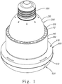
- a multi-directional LED lamp includes a cooling cylinder 100, a lamp housing unit 200, a lamp cap 300, a LED lighting unit 400, a driving circuit board 500 and a transparent lampshade unit 600 is disclosed.
- the cooling cylinder 100 is made by good heat conducting materials, such as aluminum, copper or its alloy.
- the cooling cylinder 100 includes an annular wall 110, which has a first outer end 111 and an opposite second outer end 112.
- the annular wall 110 of the cooling cylinder 100 is penetrated by a plurality of air channels 120 running through the first outer end 111 to the second outer end 112.
- a transverse carrier plate 130 is disposed between inner walls of the interior of cooling cylinder 100.
- a first annular groove 140 is set at a bottom of the inner wall of the annular wall 110 of the cooling cylinder 100 and a second annular groove 150 is set at a top of the inner wall of the annular wall 110 of the cooling cylinder 100.
- the lamp housing unit 200 includes an upper lamp housing 210 and a lower lamp housing 220.
- the lower lamp housing 220 is assembled at a basal plane of the upper lamp housing 210.
- An interior of the upper lamp housing 210 and an interior of the lower lamp housing 220 form a containing room 230.
- the lamp cap 300 is assembled at a top of the upper lamp housing 210 of the lamp housing unit 200.
- the driving circuit board 500 is installed in the containing room 230 of the interior of the lamp housing unit 200, and is electrically connected to the lamp cap 300 and the LED lighting unit 400.
- a bottom of the upper lamp housing 210 of the lamp housing unit 200 has a plurality of second engaging sections 211 spaced to each other, each of the second engaging sections 211 is engaged with the second annular groove 150 of the cooling cylinder 100.
- the LED lighting unit 400 has a substrate 410 and a plurality of LEDs 420 installed on the substrate 410.
- the LED lighting unit 400 is installed on the basal plane of the transverse carrier plate 130 of the cooling cylinder 100, and facing an opposite end of the lamp cap 300, that is, facing the direction of the transparent lampshade unit 600. Besides passing via the transverse carrier plate 130 and via a surface of the annular wall 110 of the cooling cylinder 100, the heat generated during the operation of the LEDs 420 can also pass by the natural convection of the air channels 120 at the same time.
- the transparent lampshade unit 600 is assembled at the bottom of the cooling cylinder 100, and covers the LED lighting unit 400.
- a cross-sectional area of the transparent lampshade unit 600 is greater than a cross-sectional area of the cooling cylinder 100, to thereby outwardly protrude from the cooling cylinder 100.
- the transparent lampshade unit 600 includes an upper transparent lampshade 610 and a lower transparent lampshade 620.
- the lower transparent lampshade 620 is assembled at the bottom of the upper transparent lampshade 610.
- the upper transparent lampshade 610 is a convex lampshade, which includes an upper inner wall 611, a flat shade body 612, and a lower outer wall 613 connected in order, an inner wall of the lower outer wall 613 has a plurality of inner notches 614 spaced to each other.
- the lower transparent lampshade 620 is a bowl lampshade, which has a bowl shade body 621 and an annular wall 622 connecting around the bowl shade body 621, the annular wall 622 has a plurality of outer hook bodies 623 spaced to each other, and each of the outer hook bodies 623 is engaged with one of the inner notches 614 of the upper transparent lampshade 610, to combine the upper transparent lampshade 610 and the lower transparent lampshade 620 together.
- the upper inner wall 611 of the transparent lampshade unit 600 has a plurality of first engaging sections 615 spaced to each other, which engage with the first annular groove 140 at the bottom of the cooling cylinder 100.
- the transparent lampshade unit 600 is assembled at the cooling cylinder 100 by the upper inner wall 611 of the upper transparent lampshade 610, the flat shade body 612 of the upper transparent lampshade 610 therefore is outwardly protrude from the cooling cylinder 100 a width W.
- the multi-directional LED lamp of the present invention since the flat shade body 612 of the upper transparent lampshade 610 of the transparent lampshade unit 600 is not covered by the cooling cylinder100 at the direction of the lamp cap 300, therefore, the light emitted by the LED lighting unit 400 can radiate in a direction opposite to the lamp cap 300 through the bowl shade body 621 and the annular wall 622 of the lower transparent lampshade 620, a part of the light can also reflect by the bowl shade body 621 and transmits toward a direction of the lamp cap 300 through the flat shade body 612 of the upper transparent lampshade 610, thereby achieving a goal of the multi-directional lighting and solving the problems of a dark area at the direction of the lamp cap 300.
Landscapes
- Engineering & Computer Science (AREA)
- General Engineering & Computer Science (AREA)
- Microelectronics & Electronic Packaging (AREA)
- Physics & Mathematics (AREA)
- Optics & Photonics (AREA)
- Non-Portable Lighting Devices Or Systems Thereof (AREA)
- Arrangement Of Elements, Cooling, Sealing, Or The Like Of Lighting Devices (AREA)
Claims (6)
- Lampe à DEL multidirectionnelle comprenant :un cylindre de refroidissement (100) ;une unité de logement de lampe (200), assemblée en haut du cylindre de refroidissement (100) ;un culot de lampe (300), assemblé en haut de l'unité de logement de lampe (200) ;une unité d'éclairage à DEL (400), installée à l'intérieur du cylindre de refroidissement (100) ;un circuit imprimé de pilotage (500), installé à l'intérieur de l'unité de logement de lampe (200), et connecté électriquement au culot de lampe (300) et à l'unité d'éclairage à DEL (400) ; etune unité d'abat-jour transparent (600), assemblée en bas du cylindre de refroidissement (100) et couvrant l'unité d'éclairage à DEL (400), une section transversale de l'unité d'abat-jour transparent (600) est plus grande qu'une section transversale du cylindre de refroidissement (100), pour dépasser vers l'extérieur du cylindre de refroidissement (100), dans laquelle l'unité d'abat-jour transparent (600) comprend un abat-jour transparent supérieur (610) et un abat-jour transparent inférieur (620), et l'abat-jour transparent inférieur (620) est assemblé en bas de l'abat-jour transparent supérieur (610), l'abat-jour transparent supérieur (610) est un abat-jour convexe, comprend une paroi interne supérieure (611), un corps d'abat-jour plat (612) et une paroi externe inférieure (613) raccordés dans cet ordre, une paroi interne de la paroi externe inférieure (613) comporte une pluralité d'encoches internes (614) espacées les unes des autres, l'abat-jour transparent inférieur (620) est un abat-jour en cloche, qui a un corps d'abat-jour en cloche (621) et une paroi convexe (622) se raccordant autour du corps d'abat-jour en cloche (621), la paroi convexe (622) comporte une pluralité de corps de crochet externe (623) espacés les uns des autres, et chacun des corps de crochet externe (623) est respectivement en prise avec l'une des encoches internes (614), et le corps d'abat-jour plat (612) permet à une lumière réfléchie par le corps d'abat-jour en cloche (621) de se transmettre vers une direction du culot de lampe (300) par le biais du corps d'abat-jour plat (612).
- Lampe à DEL multidirectionnelle selon la revendication 1, dans laquelle le cylindre de refroidissement (100) a une paroi annulaire (110), la paroi annulaire (110) a une première extrémité externe (111) et une seconde extrémité externe (112) opposée à la première extrémité externe (111), la paroi annulaire (110) est percée par une pluralité de canaux à air (120) circulant de la première extrémité externe (111) à la seconde extrémité externe (112), une plaque de support transversale (130) est disposée entre une paroi interne de l'intérieur du cylindre de refroidissement (100), l'unité d'éclairage à DEL (400) est installée au niveau d'un plan de base de la plaque de support transversale (130).
- Lampe à DEL multidirectionnelle selon la revendication 2, dans laquelle une première rainure annulaire (140) est située en bas de la paroi interne de la paroi annulaire (110) du cylindre de refroidissement (100), la paroi interne supérieure (611) de l'unité d'abat-jour transparent (600) comporte une pluralité de premières sections de mise en prise (615) espacées les unes des autres, chacune des premières sections de mise en prise (615) est en prise avec la première rainure annulaire (140).
- Lampe à DEL multidirectionnelle selon la revendication 2, dans laquelle l'unité de logement de lampe (200) comprend un logement de lampe supérieur (210) et un logement de lampe inférieur (220), le logement de lampe inférieur (220) est assemblé sur un plan de base du logement de lampe supérieur (210), un intérieur du logement de lampe supérieur (210) et un intérieur du logement de lampe inférieur (220) forment une chambre de confinement (230), dans laquelle le circuit imprimé de pilotage (500) est installé dans la chambre de confinement (230).
- Lampe à DEL multidirectionnelle selon la revendication 4, dans laquelle une seconde rainure annulaire (150) est située en haut de la paroi interne de la paroi annulaire (110) du cylindre de refroidissement (100), un bas du logement de lampe supérieur (210) de l'unité de logement de lampe (200) comporte une pluralité de secondes sections de mise en prise (211) espacées les unes des autres, chacune des secondes sections de mise en prise est en prise avec la seconde rainure annulaire (150).
- Lampe à DEL multidirectionnelle selon la revendication 1, dans laquelle l'unité d'éclairage à DEL (400) comprend un substrat (410) et une pluralité de DEL (420) installées sur le substrat (410).
Applications Claiming Priority (1)
| Application Number | Priority Date | Filing Date | Title |
|---|---|---|---|
| TW104102869A TWI558947B (zh) | 2015-01-28 | 2015-01-28 | Multi-directional light bulb |
Publications (2)
| Publication Number | Publication Date |
|---|---|
| EP3051202A1 EP3051202A1 (fr) | 2016-08-03 |
| EP3051202B1 true EP3051202B1 (fr) | 2017-11-29 |
Family
ID=54207318
Family Applications (1)
| Application Number | Title | Priority Date | Filing Date |
|---|---|---|---|
| EP15186561.5A Not-in-force EP3051202B1 (fr) | 2015-01-28 | 2015-09-23 | Lampe à del multidirectionnelle |
Country Status (7)
| Country | Link |
|---|---|
| US (1) | US9696003B2 (fr) |
| EP (1) | EP3051202B1 (fr) |
| DK (1) | DK3051202T3 (fr) |
| ES (1) | ES2660995T3 (fr) |
| NO (1) | NO3051202T3 (fr) |
| PT (1) | PT3051202T (fr) |
| TW (1) | TWI558947B (fr) |
Families Citing this family (3)
| Publication number | Priority date | Publication date | Assignee | Title |
|---|---|---|---|---|
| US10433418B2 (en) * | 2015-12-08 | 2019-10-01 | Signify Holding B.V. | Assembly and lighting device comprising the assembly |
| USD899639S1 (en) * | 2019-05-30 | 2020-10-20 | Shenzhen Sangshen E-commerce Co., Ltd. | LED lamp |
| USD899640S1 (en) * | 2019-05-30 | 2020-10-20 | Shenzhen Sangshen E-commerce Co., Ltd. | LED lamp |
Family Cites Families (16)
| Publication number | Priority date | Publication date | Assignee | Title |
|---|---|---|---|---|
| NL1028678C2 (nl) | 2005-04-01 | 2006-10-03 | Lemnis Lighting Ip Gmbh | Koellichaam, lamp en werkwijze voor het vervaardigen van een koellichaam. |
| TWI335402B (en) * | 2007-08-03 | 2011-01-01 | Foxconn Tech Co Ltd | Led lamp with a heat sink |
| CN101509653B (zh) * | 2009-03-09 | 2015-01-14 | 张春涛 | 带有风扇的大功率led灯结构 |
| DE102009051373A1 (de) | 2009-10-30 | 2011-05-05 | Zumtobel Lighting Gmbh | Kühlkörper für LED-Leuchte |
| CN101893176A (zh) * | 2010-07-15 | 2010-11-24 | 鸿富锦精密工业(深圳)有限公司 | Led照明灯具 |
| TWI401394B (zh) * | 2010-08-02 | 2013-07-11 | Foxsemicon Integrated Tech Inc | 燈泡及其燈殼 |
| TW201207316A (en) | 2010-08-13 | 2012-02-16 | Foxsemicon Integrated Tech Inc | Lamp and lamp envelope thereof |
| CN201748229U (zh) * | 2010-08-25 | 2011-02-16 | 品能光电(苏州)有限公司 | Led灯 |
| US8421320B2 (en) * | 2011-01-24 | 2013-04-16 | Sheng-Yi CHUANG | LED light bulb equipped with light transparent shell fastening structure |
| US8608341B2 (en) | 2011-03-07 | 2013-12-17 | Lighting Science Group Corporation | LED luminaire |
| KR101227525B1 (ko) * | 2011-08-12 | 2013-01-31 | 엘지전자 주식회사 | 조명 장치 |
| US9255674B2 (en) * | 2012-10-04 | 2016-02-09 | Once Innovations, Inc. | Method of manufacturing a light emitting diode lighting assembly |
| US9291331B2 (en) * | 2013-03-15 | 2016-03-22 | Cordelia Lighting, Inc. | Snap-on lens for LED light fixture |
| US20140307427A1 (en) | 2013-04-11 | 2014-10-16 | Lg Innotek Co., Ltd. | Lighting device |
| US10030819B2 (en) * | 2014-01-30 | 2018-07-24 | Cree, Inc. | LED lamp and heat sink |
| CN105805605A (zh) * | 2014-12-31 | 2016-07-27 | 全亿大科技(佛山)有限公司 | 灯具 |
-
2015
- 2015-01-28 TW TW104102869A patent/TWI558947B/zh not_active IP Right Cessation
- 2015-09-10 US US14/849,610 patent/US9696003B2/en not_active Expired - Fee Related
- 2015-09-23 EP EP15186561.5A patent/EP3051202B1/fr not_active Not-in-force
- 2015-09-23 PT PT151865615T patent/PT3051202T/pt unknown
- 2015-09-23 NO NO15186561A patent/NO3051202T3/no unknown
- 2015-09-23 DK DK15186561.5T patent/DK3051202T3/en active
- 2015-09-23 ES ES15186561.5T patent/ES2660995T3/es active Active
Non-Patent Citations (1)
| Title |
|---|
| None * |
Also Published As
| Publication number | Publication date |
|---|---|
| US9696003B2 (en) | 2017-07-04 |
| PT3051202T (pt) | 2018-02-21 |
| NO3051202T3 (fr) | 2018-04-28 |
| DK3051202T3 (en) | 2018-02-19 |
| ES2660995T3 (es) | 2018-03-27 |
| TW201627601A (zh) | 2016-08-01 |
| TWI558947B (zh) | 2016-11-21 |
| US20160215953A1 (en) | 2016-07-28 |
| EP3051202A1 (fr) | 2016-08-03 |
Similar Documents
| Publication | Publication Date | Title |
|---|---|---|
| US8348471B2 (en) | LED lamp assembly | |
| JP5163896B2 (ja) | 照明装置及び照明器具 | |
| US20110057551A1 (en) | Heat dissipating device for lightings | |
| US20130240920A1 (en) | Multi-direction bulb-type lamp | |
| US8764251B2 (en) | Heat dissipation structure for light bulb assembly | |
| EP2796784A1 (fr) | Structure d'ampoule et son couvercle de lampe de guidage de lumière | |
| JP2012084316A (ja) | 照明器具 | |
| US9689560B2 (en) | LED light bulb simultaneously using as nightlight | |
| EP3051202B1 (fr) | Lampe à del multidirectionnelle | |
| JP5690961B2 (ja) | 照明用光源及び照明装置 | |
| TW201312041A (zh) | 發光裝置以及照明裝置 | |
| JP3166116U (ja) | ランプヘッドモジュールと発光ダイオードバルブ | |
| US20140085908A1 (en) | Led lamp structure having free convection cooling | |
| US20130215615A1 (en) | Laterally installable rotating lamp | |
| US20140286014A1 (en) | Lamp Device and Luminaire | |
| US9423099B2 (en) | LED lamp having reflector with high heat dissipation rate | |
| TW201812207A (zh) | 照明裝置 | |
| KR20150075462A (ko) | Led 조명 장치 | |
| US20140104860A1 (en) | Lighting device for a car lamp | |
| TWM500861U (zh) | 多向出光之led燈泡 | |
| CN203231126U (zh) | Led灯 | |
| CN209782351U (zh) | 一种具有散热功能的双色温led灯具 | |
| US20150354757A1 (en) | Led lamp | |
| KR101458810B1 (ko) | 다색형 발광 다이오드 램프 | |
| KR20160073182A (ko) | 엘이디 램프 |
Legal Events
| Date | Code | Title | Description |
|---|---|---|---|
| PUAI | Public reference made under article 153(3) epc to a published international application that has entered the european phase |
Free format text: ORIGINAL CODE: 0009012 |
|
| 17P | Request for examination filed |
Effective date: 20160510 |
|
| AK | Designated contracting states |
Kind code of ref document: A1 Designated state(s): AL AT BE BG CH CY CZ DE DK EE ES FI FR GB GR HR HU IE IS IT LI LT LU LV MC MK MT NL NO PL PT RO RS SE SI SK SM TR |
|
| AX | Request for extension of the european patent |
Extension state: BA ME |
|
| GRAP | Despatch of communication of intention to grant a patent |
Free format text: ORIGINAL CODE: EPIDOSNIGR1 |
|
| RIC1 | Information provided on ipc code assigned before grant |
Ipc: F21V 23/00 20150101ALI20170522BHEP Ipc: F21Y 115/10 20160101ALN20170522BHEP Ipc: F21K 9/66 20160101ALI20170522BHEP Ipc: F21V 3/02 20060101AFI20170522BHEP Ipc: F21K 9/232 20160101ALI20170522BHEP Ipc: F21V 17/16 20060101ALI20170522BHEP |
|
| INTG | Intention to grant announced |
Effective date: 20170623 |
|
| GRAS | Grant fee paid |
Free format text: ORIGINAL CODE: EPIDOSNIGR3 |
|
| GRAA | (expected) grant |
Free format text: ORIGINAL CODE: 0009210 |
|
| AK | Designated contracting states |
Kind code of ref document: B1 Designated state(s): AL AT BE BG CH CY CZ DE DK EE ES FI FR GB GR HR HU IE IS IT LI LT LU LV MC MK MT NL NO PL PT RO RS SE SI SK SM TR |
|
| REG | Reference to a national code |
Ref country code: CH Ref legal event code: EP |
|
| REG | Reference to a national code |
Ref country code: AT Ref legal event code: REF Ref document number: 950719 Country of ref document: AT Kind code of ref document: T Effective date: 20171215 |
|
| REG | Reference to a national code |
Ref country code: IE Ref legal event code: FG4D |
|
| REG | Reference to a national code |
Ref country code: DE Ref legal event code: R096 Ref document number: 602015006298 Country of ref document: DE |
|
| REG | Reference to a national code |
Ref country code: DK Ref legal event code: T3 Effective date: 20180215 |
|
| REG | Reference to a national code |
Ref country code: NL Ref legal event code: FP Ref country code: PT Ref legal event code: SC4A Ref document number: 3051202 Country of ref document: PT Date of ref document: 20180221 Kind code of ref document: T Free format text: AVAILABILITY OF NATIONAL TRANSLATION Effective date: 20180212 |
|
| REG | Reference to a national code |
Ref country code: SE Ref legal event code: TRGR |
|
| REG | Reference to a national code |
Ref country code: CH Ref legal event code: NV Representative=s name: MICHELI AND CIE SA, CH |
|
| REG | Reference to a national code |
Ref country code: ES Ref legal event code: FG2A Ref document number: 2660995 Country of ref document: ES Kind code of ref document: T3 Effective date: 20180327 |
|
| REG | Reference to a national code |
Ref country code: LT Ref legal event code: MG4D |
|
| PG25 | Lapsed in a contracting state [announced via postgrant information from national office to epo] |
Ref country code: LT Free format text: LAPSE BECAUSE OF FAILURE TO SUBMIT A TRANSLATION OF THE DESCRIPTION OR TO PAY THE FEE WITHIN THE PRESCRIBED TIME-LIMIT Effective date: 20171129 Ref country code: FI Free format text: LAPSE BECAUSE OF FAILURE TO SUBMIT A TRANSLATION OF THE DESCRIPTION OR TO PAY THE FEE WITHIN THE PRESCRIBED TIME-LIMIT Effective date: 20171129 |
|
| REG | Reference to a national code |
Ref country code: NO Ref legal event code: T2 Effective date: 20171129 |
|
| PG25 | Lapsed in a contracting state [announced via postgrant information from national office to epo] |
Ref country code: GR Free format text: LAPSE BECAUSE OF FAILURE TO SUBMIT A TRANSLATION OF THE DESCRIPTION OR TO PAY THE FEE WITHIN THE PRESCRIBED TIME-LIMIT Effective date: 20180301 Ref country code: BG Free format text: LAPSE BECAUSE OF FAILURE TO SUBMIT A TRANSLATION OF THE DESCRIPTION OR TO PAY THE FEE WITHIN THE PRESCRIBED TIME-LIMIT Effective date: 20180228 Ref country code: HR Free format text: LAPSE BECAUSE OF FAILURE TO SUBMIT A TRANSLATION OF THE DESCRIPTION OR TO PAY THE FEE WITHIN THE PRESCRIBED TIME-LIMIT Effective date: 20171129 Ref country code: RS Free format text: LAPSE BECAUSE OF FAILURE TO SUBMIT A TRANSLATION OF THE DESCRIPTION OR TO PAY THE FEE WITHIN THE PRESCRIBED TIME-LIMIT Effective date: 20171129 Ref country code: LV Free format text: LAPSE BECAUSE OF FAILURE TO SUBMIT A TRANSLATION OF THE DESCRIPTION OR TO PAY THE FEE WITHIN THE PRESCRIBED TIME-LIMIT Effective date: 20171129 |
|
| PG25 | Lapsed in a contracting state [announced via postgrant information from national office to epo] |
Ref country code: CZ Free format text: LAPSE BECAUSE OF FAILURE TO SUBMIT A TRANSLATION OF THE DESCRIPTION OR TO PAY THE FEE WITHIN THE PRESCRIBED TIME-LIMIT Effective date: 20171129 Ref country code: EE Free format text: LAPSE BECAUSE OF FAILURE TO SUBMIT A TRANSLATION OF THE DESCRIPTION OR TO PAY THE FEE WITHIN THE PRESCRIBED TIME-LIMIT Effective date: 20171129 Ref country code: CY Free format text: LAPSE BECAUSE OF FAILURE TO SUBMIT A TRANSLATION OF THE DESCRIPTION OR TO PAY THE FEE WITHIN THE PRESCRIBED TIME-LIMIT Effective date: 20171129 Ref country code: SK Free format text: LAPSE BECAUSE OF FAILURE TO SUBMIT A TRANSLATION OF THE DESCRIPTION OR TO PAY THE FEE WITHIN THE PRESCRIBED TIME-LIMIT Effective date: 20171129 |
|
| REG | Reference to a national code |
Ref country code: DE Ref legal event code: R097 Ref document number: 602015006298 Country of ref document: DE |
|
| PG25 | Lapsed in a contracting state [announced via postgrant information from national office to epo] |
Ref country code: SM Free format text: LAPSE BECAUSE OF FAILURE TO SUBMIT A TRANSLATION OF THE DESCRIPTION OR TO PAY THE FEE WITHIN THE PRESCRIBED TIME-LIMIT Effective date: 20171129 Ref country code: RO Free format text: LAPSE BECAUSE OF FAILURE TO SUBMIT A TRANSLATION OF THE DESCRIPTION OR TO PAY THE FEE WITHIN THE PRESCRIBED TIME-LIMIT Effective date: 20171129 Ref country code: PL Free format text: LAPSE BECAUSE OF FAILURE TO SUBMIT A TRANSLATION OF THE DESCRIPTION OR TO PAY THE FEE WITHIN THE PRESCRIBED TIME-LIMIT Effective date: 20171129 |
|
| PLBE | No opposition filed within time limit |
Free format text: ORIGINAL CODE: 0009261 |
|
| STAA | Information on the status of an ep patent application or granted ep patent |
Free format text: STATUS: NO OPPOSITION FILED WITHIN TIME LIMIT |
|
| PGFP | Annual fee paid to national office [announced via postgrant information from national office to epo] |
Ref country code: IT Payment date: 20180930 Year of fee payment: 4 Ref country code: DE Payment date: 20180912 Year of fee payment: 4 |
|
| 26N | No opposition filed |
Effective date: 20180830 |
|
| PG25 | Lapsed in a contracting state [announced via postgrant information from national office to epo] |
Ref country code: SI Free format text: LAPSE BECAUSE OF FAILURE TO SUBMIT A TRANSLATION OF THE DESCRIPTION OR TO PAY THE FEE WITHIN THE PRESCRIBED TIME-LIMIT Effective date: 20171129 |
|
| REG | Reference to a national code |
Ref country code: NO Ref legal event code: MMEP |
|
| PG25 | Lapsed in a contracting state [announced via postgrant information from national office to epo] |
Ref country code: MC Free format text: LAPSE BECAUSE OF FAILURE TO SUBMIT A TRANSLATION OF THE DESCRIPTION OR TO PAY THE FEE WITHIN THE PRESCRIBED TIME-LIMIT Effective date: 20171129 |
|
| REG | Reference to a national code |
Ref country code: SE Ref legal event code: EUG Ref country code: CH Ref legal event code: PL |
|
| REG | Reference to a national code |
Ref country code: DK Ref legal event code: EBP Effective date: 20180930 |
|
| REG | Reference to a national code |
Ref country code: NL Ref legal event code: MM Effective date: 20181001 |
|
| PG25 | Lapsed in a contracting state [announced via postgrant information from national office to epo] |
Ref country code: SE Free format text: LAPSE BECAUSE OF NON-PAYMENT OF DUE FEES Effective date: 20180924 |
|
| REG | Reference to a national code |
Ref country code: BE Ref legal event code: MM Effective date: 20180930 |
|
| REG | Reference to a national code |
Ref country code: IE Ref legal event code: MM4A |
|
| PG25 | Lapsed in a contracting state [announced via postgrant information from national office to epo] |
Ref country code: NL Free format text: LAPSE BECAUSE OF NON-PAYMENT OF DUE FEES Effective date: 20181001 Ref country code: LU Free format text: LAPSE BECAUSE OF NON-PAYMENT OF DUE FEES Effective date: 20180923 |
|
| PG25 | Lapsed in a contracting state [announced via postgrant information from national office to epo] |
Ref country code: IE Free format text: LAPSE BECAUSE OF NON-PAYMENT OF DUE FEES Effective date: 20180923 Ref country code: NO Free format text: LAPSE BECAUSE OF NON-PAYMENT OF DUE FEES Effective date: 20180930 Ref country code: PT Free format text: LAPSE BECAUSE OF NON-PAYMENT OF DUE FEES Effective date: 20190624 |
|
| PG25 | Lapsed in a contracting state [announced via postgrant information from national office to epo] |
Ref country code: BE Free format text: LAPSE BECAUSE OF NON-PAYMENT OF DUE FEES Effective date: 20180930 Ref country code: FR Free format text: LAPSE BECAUSE OF NON-PAYMENT OF DUE FEES Effective date: 20180930 Ref country code: LI Free format text: LAPSE BECAUSE OF NON-PAYMENT OF DUE FEES Effective date: 20180930 Ref country code: CH Free format text: LAPSE BECAUSE OF NON-PAYMENT OF DUE FEES Effective date: 20180930 |
|
| REG | Reference to a national code |
Ref country code: ES Ref legal event code: FD2A Effective date: 20191030 |
|
| PG25 | Lapsed in a contracting state [announced via postgrant information from national office to epo] |
Ref country code: DK Free format text: LAPSE BECAUSE OF NON-PAYMENT OF DUE FEES Effective date: 20180930 |
|
| PG25 | Lapsed in a contracting state [announced via postgrant information from national office to epo] |
Ref country code: MT Free format text: LAPSE BECAUSE OF NON-PAYMENT OF DUE FEES Effective date: 20180923 |
|
| PG25 | Lapsed in a contracting state [announced via postgrant information from national office to epo] |
Ref country code: ES Free format text: LAPSE BECAUSE OF NON-PAYMENT OF DUE FEES Effective date: 20180924 |
|
| PG25 | Lapsed in a contracting state [announced via postgrant information from national office to epo] |
Ref country code: TR Free format text: LAPSE BECAUSE OF FAILURE TO SUBMIT A TRANSLATION OF THE DESCRIPTION OR TO PAY THE FEE WITHIN THE PRESCRIBED TIME-LIMIT Effective date: 20171129 |
|
| REG | Reference to a national code |
Ref country code: DE Ref legal event code: R119 Ref document number: 602015006298 Country of ref document: DE |
|
| REG | Reference to a national code |
Ref country code: AT Ref legal event code: UEP Ref document number: 950719 Country of ref document: AT Kind code of ref document: T Effective date: 20171129 |
|
| PG25 | Lapsed in a contracting state [announced via postgrant information from national office to epo] |
Ref country code: HU Free format text: LAPSE BECAUSE OF FAILURE TO SUBMIT A TRANSLATION OF THE DESCRIPTION OR TO PAY THE FEE WITHIN THE PRESCRIBED TIME-LIMIT; INVALID AB INITIO Effective date: 20150923 Ref country code: MK Free format text: LAPSE BECAUSE OF NON-PAYMENT OF DUE FEES Effective date: 20171129 |
|
| PG25 | Lapsed in a contracting state [announced via postgrant information from national office to epo] |
Ref country code: DE Free format text: LAPSE BECAUSE OF NON-PAYMENT OF DUE FEES Effective date: 20200401 Ref country code: AL Free format text: LAPSE BECAUSE OF FAILURE TO SUBMIT A TRANSLATION OF THE DESCRIPTION OR TO PAY THE FEE WITHIN THE PRESCRIBED TIME-LIMIT Effective date: 20171129 Ref country code: IS Free format text: LAPSE BECAUSE OF FAILURE TO SUBMIT A TRANSLATION OF THE DESCRIPTION OR TO PAY THE FEE WITHIN THE PRESCRIBED TIME-LIMIT Effective date: 20180329 |
|
| PG25 | Lapsed in a contracting state [announced via postgrant information from national office to epo] |
Ref country code: IT Free format text: LAPSE BECAUSE OF NON-PAYMENT OF DUE FEES Effective date: 20190923 |
|
| GBPC | Gb: european patent ceased through non-payment of renewal fee |
Effective date: 20190923 |
|
| PG25 | Lapsed in a contracting state [announced via postgrant information from national office to epo] |
Ref country code: GB Free format text: LAPSE BECAUSE OF NON-PAYMENT OF DUE FEES Effective date: 20190923 |
|
| REG | Reference to a national code |
Ref country code: AT Ref legal event code: MM01 Ref document number: 950719 Country of ref document: AT Kind code of ref document: T Effective date: 20200923 |
|
| PG25 | Lapsed in a contracting state [announced via postgrant information from national office to epo] |
Ref country code: AT Free format text: LAPSE BECAUSE OF NON-PAYMENT OF DUE FEES Effective date: 20200923 |