EP3051069B1 - Method of assembling of a gas turbine engine section - Google Patents
Method of assembling of a gas turbine engine section Download PDFInfo
- Publication number
- EP3051069B1 EP3051069B1 EP16152936.7A EP16152936A EP3051069B1 EP 3051069 B1 EP3051069 B1 EP 3051069B1 EP 16152936 A EP16152936 A EP 16152936A EP 3051069 B1 EP3051069 B1 EP 3051069B1
- Authority
- EP
- European Patent Office
- Prior art keywords
- section
- vane
- row
- vanes
- compressor
- Prior art date
- Legal status (The legal status is an assumption and is not a legal conclusion. Google has not performed a legal analysis and makes no representation as to the accuracy of the status listed.)
- Active
Links
Images


Classifications
-
- F—MECHANICAL ENGINEERING; LIGHTING; HEATING; WEAPONS; BLASTING
- F01—MACHINES OR ENGINES IN GENERAL; ENGINE PLANTS IN GENERAL; STEAM ENGINES
- F01D—NON-POSITIVE DISPLACEMENT MACHINES OR ENGINES, e.g. STEAM TURBINES
- F01D25/00—Component parts, details, or accessories, not provided for in, or of interest apart from, other groups
- F01D25/24—Casings; Casing parts, e.g. diaphragms, casing fastenings
- F01D25/246—Fastening of diaphragms or stator-rings
-
- B—PERFORMING OPERATIONS; TRANSPORTING
- B23—MACHINE TOOLS; METAL-WORKING NOT OTHERWISE PROVIDED FOR
- B23K—SOLDERING OR UNSOLDERING; WELDING; CLADDING OR PLATING BY SOLDERING OR WELDING; CUTTING BY APPLYING HEAT LOCALLY, e.g. FLAME CUTTING; WORKING BY LASER BEAM
- B23K31/00—Processes relevant to this subclass, specially adapted for particular articles or purposes, but not covered by only one of the preceding main groups
- B23K31/02—Processes relevant to this subclass, specially adapted for particular articles or purposes, but not covered by only one of the preceding main groups relating to soldering or welding
-
- F—MECHANICAL ENGINEERING; LIGHTING; HEATING; WEAPONS; BLASTING
- F01—MACHINES OR ENGINES IN GENERAL; ENGINE PLANTS IN GENERAL; STEAM ENGINES
- F01D—NON-POSITIVE DISPLACEMENT MACHINES OR ENGINES, e.g. STEAM TURBINES
- F01D17/00—Regulating or controlling by varying flow
- F01D17/10—Final actuators
- F01D17/12—Final actuators arranged in stator parts
- F01D17/14—Final actuators arranged in stator parts varying effective cross-sectional area of nozzles or guide conduits
- F01D17/16—Final actuators arranged in stator parts varying effective cross-sectional area of nozzles or guide conduits by means of nozzle vanes
- F01D17/162—Final actuators arranged in stator parts varying effective cross-sectional area of nozzles or guide conduits by means of nozzle vanes for axial flow, i.e. the vanes turning around axes which are essentially perpendicular to the rotor centre line
-
- F—MECHANICAL ENGINEERING; LIGHTING; HEATING; WEAPONS; BLASTING
- F01—MACHINES OR ENGINES IN GENERAL; ENGINE PLANTS IN GENERAL; STEAM ENGINES
- F01D—NON-POSITIVE DISPLACEMENT MACHINES OR ENGINES, e.g. STEAM TURBINES
- F01D5/00—Blades; Blade-carrying members; Heating, heat-insulating, cooling or antivibration means on the blades or the members
- F01D5/02—Blade-carrying members, e.g. rotors
- F01D5/06—Rotors for more than one axial stage, e.g. of drum or multiple disc type; Details thereof, e.g. shafts, shaft connections
- F01D5/063—Welded rotors
-
- F—MECHANICAL ENGINEERING; LIGHTING; HEATING; WEAPONS; BLASTING
- F01—MACHINES OR ENGINES IN GENERAL; ENGINE PLANTS IN GENERAL; STEAM ENGINES
- F01D—NON-POSITIVE DISPLACEMENT MACHINES OR ENGINES, e.g. STEAM TURBINES
- F01D9/00—Stators
- F01D9/02—Nozzles; Nozzle boxes; Stator blades; Guide conduits, e.g. individual nozzles
- F01D9/04—Nozzles; Nozzle boxes; Stator blades; Guide conduits, e.g. individual nozzles forming ring or sector
- F01D9/041—Nozzles; Nozzle boxes; Stator blades; Guide conduits, e.g. individual nozzles forming ring or sector using blades
-
- F—MECHANICAL ENGINEERING; LIGHTING; HEATING; WEAPONS; BLASTING
- F01—MACHINES OR ENGINES IN GENERAL; ENGINE PLANTS IN GENERAL; STEAM ENGINES
- F01D—NON-POSITIVE DISPLACEMENT MACHINES OR ENGINES, e.g. STEAM TURBINES
- F01D9/00—Stators
- F01D9/02—Nozzles; Nozzle boxes; Stator blades; Guide conduits, e.g. individual nozzles
- F01D9/04—Nozzles; Nozzle boxes; Stator blades; Guide conduits, e.g. individual nozzles forming ring or sector
- F01D9/042—Nozzles; Nozzle boxes; Stator blades; Guide conduits, e.g. individual nozzles forming ring or sector fixing blades to stators
-
- F—MECHANICAL ENGINEERING; LIGHTING; HEATING; WEAPONS; BLASTING
- F02—COMBUSTION ENGINES; HOT-GAS OR COMBUSTION-PRODUCT ENGINE PLANTS
- F02C—GAS-TURBINE PLANTS; AIR INTAKES FOR JET-PROPULSION PLANTS; CONTROLLING FUEL SUPPLY IN AIR-BREATHING JET-PROPULSION PLANTS
- F02C9/00—Controlling gas-turbine plants; Controlling fuel supply in air- breathing jet-propulsion plants
- F02C9/16—Control of working fluid flow
- F02C9/20—Control of working fluid flow by throttling; by adjusting vanes
- F02C9/22—Control of working fluid flow by throttling; by adjusting vanes by adjusting turbine vanes
-
- F—MECHANICAL ENGINEERING; LIGHTING; HEATING; WEAPONS; BLASTING
- F05—INDEXING SCHEMES RELATING TO ENGINES OR PUMPS IN VARIOUS SUBCLASSES OF CLASSES F01-F04
- F05D—INDEXING SCHEME FOR ASPECTS RELATING TO NON-POSITIVE-DISPLACEMENT MACHINES OR ENGINES, GAS-TURBINES OR JET-PROPULSION PLANTS
- F05D2220/00—Application
- F05D2220/30—Application in turbines
- F05D2220/32—Application in turbines in gas turbines
-
- F—MECHANICAL ENGINEERING; LIGHTING; HEATING; WEAPONS; BLASTING
- F05—INDEXING SCHEMES RELATING TO ENGINES OR PUMPS IN VARIOUS SUBCLASSES OF CLASSES F01-F04
- F05D—INDEXING SCHEME FOR ASPECTS RELATING TO NON-POSITIVE-DISPLACEMENT MACHINES OR ENGINES, GAS-TURBINES OR JET-PROPULSION PLANTS
- F05D2230/00—Manufacture
- F05D2230/20—Manufacture essentially without removing material
- F05D2230/23—Manufacture essentially without removing material by permanently joining parts together
- F05D2230/232—Manufacture essentially without removing material by permanently joining parts together by welding
-
- F—MECHANICAL ENGINEERING; LIGHTING; HEATING; WEAPONS; BLASTING
- F05—INDEXING SCHEMES RELATING TO ENGINES OR PUMPS IN VARIOUS SUBCLASSES OF CLASSES F01-F04
- F05D—INDEXING SCHEME FOR ASPECTS RELATING TO NON-POSITIVE-DISPLACEMENT MACHINES OR ENGINES, GAS-TURBINES OR JET-PROPULSION PLANTS
- F05D2230/00—Manufacture
- F05D2230/60—Assembly methods
-
- Y—GENERAL TAGGING OF NEW TECHNOLOGICAL DEVELOPMENTS; GENERAL TAGGING OF CROSS-SECTIONAL TECHNOLOGIES SPANNING OVER SEVERAL SECTIONS OF THE IPC; TECHNICAL SUBJECTS COVERED BY FORMER USPC CROSS-REFERENCE ART COLLECTIONS [XRACs] AND DIGESTS
- Y10—TECHNICAL SUBJECTS COVERED BY FORMER USPC
- Y10T—TECHNICAL SUBJECTS COVERED BY FORMER US CLASSIFICATION
- Y10T29/00—Metal working
- Y10T29/49—Method of mechanical manufacture
- Y10T29/49316—Impeller making
- Y10T29/4932—Turbomachine making
- Y10T29/49321—Assembling individual fluid flow interacting members, e.g., blades, vanes, buckets, on rotary support member
-
- Y—GENERAL TAGGING OF NEW TECHNOLOGICAL DEVELOPMENTS; GENERAL TAGGING OF CROSS-SECTIONAL TECHNOLOGIES SPANNING OVER SEVERAL SECTIONS OF THE IPC; TECHNICAL SUBJECTS COVERED BY FORMER USPC CROSS-REFERENCE ART COLLECTIONS [XRACs] AND DIGESTS
- Y10—TECHNICAL SUBJECTS COVERED BY FORMER USPC
- Y10T—TECHNICAL SUBJECTS COVERED BY FORMER US CLASSIFICATION
- Y10T29/00—Metal working
- Y10T29/49—Method of mechanical manufacture
- Y10T29/49826—Assembling or joining
- Y10T29/49895—Associating parts by use of aligning means [e.g., use of a drift pin or a "fixture"]
-
- Y—GENERAL TAGGING OF NEW TECHNOLOGICAL DEVELOPMENTS; GENERAL TAGGING OF CROSS-SECTIONAL TECHNOLOGIES SPANNING OVER SEVERAL SECTIONS OF THE IPC; TECHNICAL SUBJECTS COVERED BY FORMER USPC CROSS-REFERENCE ART COLLECTIONS [XRACs] AND DIGESTS
- Y10—TECHNICAL SUBJECTS COVERED BY FORMER USPC
- Y10T—TECHNICAL SUBJECTS COVERED BY FORMER US CLASSIFICATION
- Y10T29/00—Metal working
- Y10T29/49—Method of mechanical manufacture
- Y10T29/49826—Assembling or joining
- Y10T29/49904—Assembling a subassembly, then assembling with a second subassembly
-
- Y—GENERAL TAGGING OF NEW TECHNOLOGICAL DEVELOPMENTS; GENERAL TAGGING OF CROSS-SECTIONAL TECHNOLOGIES SPANNING OVER SEVERAL SECTIONS OF THE IPC; TECHNICAL SUBJECTS COVERED BY FORMER USPC CROSS-REFERENCE ART COLLECTIONS [XRACs] AND DIGESTS
- Y10—TECHNICAL SUBJECTS COVERED BY FORMER USPC
- Y10T—TECHNICAL SUBJECTS COVERED BY FORMER US CLASSIFICATION
- Y10T29/00—Metal working
- Y10T29/49—Method of mechanical manufacture
- Y10T29/49826—Assembling or joining
- Y10T29/49947—Assembling or joining by applying separate fastener
- Y10T29/49963—Threaded fastener
Definitions
- the present invention refers to a method of assembling a section of a gas turbine engine.
- a gas turbine engine typically includes a fan section, a compressor section, a combustor section and a turbine section. Air entering the compressor section is compressed and delivered into the combustion section where it is mixed with fuel and ignited to generate a high-speed exhaust gas flow. The high-speed exhaust gas flow expands through the turbine section to drive the compressor and the fan section.
- the compressor section typically includes low and high pressure compressors, and the turbine section includes low and high pressure turbines.
- the high pressure turbine drives the high pressure compressor through a high spool
- the low pressure turbine drives the low pressure compressor through a low spool.
- the fan section may also be driven by the low spool.
- a direct-drive gas turbine engine includes a fan section driven by the low spool, without a gear mechanism, such that the low pressure compressor, low pressure turbine and fan section rotate at a common speed.
- US 2011/0223013 A1 discloses a reduced monobloc multistage drum of axial compressor.
- the plurality of vane arc segments have equivalent arc lengths.
- the plurality of vane arc segments have different arc lengths.
- a further embodiment of any of the foregoing embodiments includes providing a seal at an interface between two of the plurality of vane arc segments.
- each of the plurality of vane arc segments includes a plurality of vanes in a vane support structure.
- the multi-row rotor drum and the vane segments are in a high compressor section of a gas turbine engine.
- FIG 1 schematically illustrates a gas turbine engine 20 ("engine 20").
- the engine 20 has a direct-drive engine architecture. Unlike a geared engine architecture that drives the fan through a gear mechanism to change the rotational speed of the fan relative to the driving portion of the turbine, a direct-drive engine architecture drives the fan without such a gear mechanism such that the fan rotates at the same speed as the driving portion of the turbine.
- the engine 20 is a two-spool arrangement that generally includes a fan section 22, a compressor section 24, a combustor section 26, and a turbine section 28.
- these sections are arranged serially along engine central axis A with respect to flow through the engine 20, although the examples herein may also be applicable to reverse-flow arrangements and other multi-spool arrangements, such as three-spool arrangements.
- the engine 20 includes a first (or low) spool 30 and a second (or high) spool 32 mounted on bearing systems 38 for concentric rotation about the engine central axis A relative to an engine static structure 36.
- bearing systems 38 are shown at various locations, these locations can vary as appropriate to the engine design, and fewer or additional bearing systems 38 may be provided.
- the first spool 30 may be referred to as a low speed spool and the second spool 32 may be referred to as a high speed spool, relative to the speed of the low speed spool.
- the compressor section 24 includes a low compressor section 24a and a high compressor section 24b
- the turbine section 28 includes a low turbine section 28a and a high turbine section 28b.
- the low compressor section 24a may also be referred to as a low pressure compressor and the high compressor section 24b may be referred to as a high pressure compressor, relative to pressure in the low pressure compressor.
- the low turbine section 28a may also be referred to as a low pressure turbine and the high turbine section 28b may be referred to as a high pressure turbine, relative to pressure in the low pressure turbine.
- the low compressor section 24a and the high compressor section 24b include, respectively, rows of rotatable compressor blades 40a and 40b that are interleaved with rows of static compressor vanes 42a and 42b.
- a row of compressor vanes and an adjacent row of compressor blades are a compressor stage.
- the low turbine section 28a and the high turbine section 28b include, respectively, rows of rotatable turbine blades 44a and 44b that are interleaved with rows of static turbine vanes 46a and 46b.
- a row of turbine vanes and an adjacent row of turbine blades are a turbine stage.
- the low turbine section 28a has four stages. In other examples, the low turbine section 28a may have three or fewer stages. In other examples, the low turbine section 28a may have more than four stages such as, for example, five, six, or seven stages.
- the fan section 22 includes at least one row of fan blades 22a.
- a case 48 extends around the fan section 22 and bounds an outer periphery of a bypass passage 50.
- the fan blades 22a are located generally at the inlet of the bypass passage 50.
- One or more rows of guide vanes 52 can be provided downstream from the fan blades 22a.
- the guide vanes 52 extend between the case 48 and the static structure 36.
- the combustion section 26 includes a combustor 54.
- the combustor 54 is arranged axially between the high compressor section 24b and the high turbine section 28b.
- the first spool 30 directly couples the low turbine section 28a with the low compressor section 24a and the fan section 22.
- the second spool 32 couples the high turbine section 28b with the high compressor section 24b. Since there is no gear mechanism in the interconnection between the low turbine section 28a and the fan section 22, the engine 20 is a direct-drive engine architecture, and the fan section 22 will rotate at the same rotational speed as the low turbine section 28a.
- the compressor section 24, the combustor section 26, and the turbine section 28 form a core engine, which drives the fan section 22.
- the compressor section 24 drives core air C along a core flow path through the low compressor section 24a and then the high compressor section 24b.
- Compressed air from the high compressor section 24b is mixed with fuel and burned in the combustor 54 to generate an exhaust gas stream.
- the exhaust gas stream is expanded through the high turbine section 28b and then the low turbine section 28a.
- the expansion over the high turbine section 28b rotationally drives the second spool 32 to thus drive the high compressor section 24b.
- the expansion over the low turbine section 28a rotationally drives the first spool 30 to thus drive the low compressor section 24a and the fan section 22.
- the rotation of the fan section 22 drives bypass air B through the bypass passage 50 (to provide a significant amount of the thrust of the engine 20) and core air C to the low compressor section 42a.
- the bypass ratio is the ratio of the amount of air that passes through the bypass passage 50 as bypass air B to the amount of air that passes through the core engine as core air C at a given performance point.
- a direct drive turbofan engine will not be able to exceed a bypass ratio of about 8 due to engine performance limitations.
- the core engine includes a bypass ratio of 8.5 - 11 even without a gear and with an engine has a thrust rating equal to or less than 40,000 pounds (18,180 kg).
- the thrust rating is from 30,000 pounds (13,640 kg) to 40,000 pounds (18,180 kg), and the overall pressure ratio (“OPR”) is approximately 40 to approximately 50.
- the OPR is the ratio of stagnation pressure at the inlet of the fan section 22, such as at P 1 in Figure 1 , to the stagnation pressure at the outlet of the high compressor section 24b, such as at P 2 in Figure 1 .
- the performance point for determining the overall pressure ratios herein is the flight condition at the top of climb prior to leveling off for cruise flight condition.
- the performance point for determining the bypass ratios herein is a particular flight condition -- typically cruise at about 0.8 Mach and about 35,000 feet (10,668 m).
- the flight condition of 0.8 Mach and 35,000 ft is the ratio of stagnation pressure at the inlet of the fan section 22, such as at P 1 in Figure 1 , to the stagnation pressure at the outlet of the high compressor section 24b, such as at P 2 in Figure 1 .
- the performance point for determining the overall pressure ratios herein is the flight condition at the top of climb prior to leveling off for cruise flight condition.
- the performance point for determining the bypass ratios herein is a particular flight condition -- typically cruise at
- the fan section 22 (at the root of the fan blades 22a), the low compressor section 24a and the high compressor section 24b together have an OPR of approximately 40 to approximately 60
- enhanced performance can be achieved by including a first row of turbine blades 46b of the high turbine section 28b that has an operating temperature of approximately 2700°F to approximately 3000°F (approximately 1482°C to approximately 1649°C) at maximum takeoff thrust, and with an engine that has a thrust rating equal to or less than 40,000 pounds (18,180 kg).
- the thrust rating is from 30,000 pounds to 40,000 pounds (13,640 kg to 18,180 kg), and the OPR is approximately 40 to approximately 50.
- the bypass ratio is greater than 4 and the OPR is greater than 40, and in one additional example embodiment the bypass ratio is 8.5-11 and the OPR is greater than 55.
- the row of blades 22a of the fan section 22 have a fan diameter, D fan
- the high compressor section 24b has a final compressor blade row prior to the combustor section 26 that has a compressor diameter, D comp
- the stages of the low turbine section 28a have a maximum diameter, D turb .
- the fan diameter, the compressor diameter, and the maximum diameter of the low turbine section 28a have an interdependence represented by a scalable ratio D fan /D comp from 3.5 to 5.0 and a scalable ratio D fan /D turb from 1.4 to 1.8, and the fan diameter is at least 68 inches.
- the interdependence is such that the value of any one of the fan diameter, the compressor diameter, and the maximum diameter depends on the values of the other two through the above ratios.
- Figure 2 illustrates selected portions of a further example of the high compressor section 24b.
- the high compressor section 24b includes a multi-row integrally bladed rotor drum 60 that is formed of a single-piece body 62.
- the single-piece body 62 instead of bonded joints or mechanical joints that are used to secure several hub pieces together, the single-piece body 62 includes no joints.
- the single-piece body 62 is a single, continuous piece of material.
- the multi-row integrally bladed rotor drum 60 includes one or more bonded joints that serve solely, or at least primarily, to hold the multi-row integrally bladed rotor drum 60 together as a unit.
- the multi-row integrally bladed rotor drum 60 may include one or more mechanical joints that supplement the one or more bonded joints.
- a bonded joint may be a joint that is secured by an adhesive, by pressure, by heat, or a combination thereof, such that there is a distinct boundary or discontinuity between the bonded portions that is at least microscopically discernible.
- Weld and braze joints are examples of bonded, metallurgical joints.
- the multi-row integrally bladed rotor drum 60 presents a challenge to assembly of the high compressor section 24b.
- a continuous hoop vane assembly can be assembled axially between rotors.
- the single-piece body 62 may not permit this assembly approach because the blades would interfere with the vanes of the vane assembly during installation; therefore, a different assembly methodology that meets this challenge is needed.
- assembly can include assembling sections of the high compressor section 24b into the engine 20 to form the high compressor section 24b in the engine 20, or assembling the sections to separately form the high compressor section 24b and then assembling the high compressor section 24b into the engine 20.
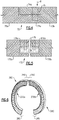
- the compressor vanes 42b that are axially between the rows of the compressor blades 40b of the multi-row integrally bladed rotor drum 60 are in a split vane assembly 70, shown in Figure 3 .
- the split vane assembly 70 includes two 180° arc segments 70a and 70b.
- the arc segments 70a/70b can each be inserted in a radial direction (see "R" Figure 2 ) into an assembled position between the rows of the compressor blades 40b to provide the row of compressor vanes 42b.
- the arc segments 70a and 70b have unequal arc lengths.
- the vane assembly 70 could have three or more arc segments, which may have equal or unequal arc lengths, or a combination thereof.
- FIG. 4 illustrates an overlapping joint, according to the invention.
- the arc segments 70a/70b include, respectively, tabs 74a/74b that overlap with respect to the radial direction R.
- the overlapping joint 72 can serve any or all of several functions, including but not limited to, facilitating alignment of the arc segments 70a/70b, locking the arc segments 70a/70b, and providing labyrinth sealing at the interface.
- one or more alignment pins 75 can also be used to facilitate axial alignment.
- Figure 5 illustrates another example joint 172.
- like reference numerals designate like elements where appropriate and reference numerals with the addition of one-hundred or multiples thereof designate modified elements that are understood to incorporate the same features and benefits of the corresponding elements.
- the arc segments 170a/170b include, respectively, slots 176a/176b.
- the slots 170a/170b cooperatively retain a circumferential seal element 178 in the interface of the joint 172, to reduce the potential for the escape of core air.
- at least portions of the interfaces can be non-mechanically bonded, such as by weld or braze, to provide sealing.
- one or more alignment pins 175 can also be used to facilitate axial alignment.
- Figure 6 illustrates a further embodiment of the invention in which arc segments 270a/270b include end portions 280 that are stronger than intermediate portions 282 of the arc segments 270a/270b.
- the end portions 280 are made stronger by adding mechanical features, such as increased thickness of vanes 42b in the end portions 280 relative to the other vanes in the arc segment 270a/270b or features in the end portions 280 that allow for structural bonding of the end portions 280 in addition to the arc segments, as described in Figure 4 and 5 .
- the end portions 280 are made stronger by using a different, stronger material for the end portions than the intermediate portions 282. The stronger end portions 280 resist deflection of the full vane ring at the joints between the arc segments 270a/270b, which may reduce "ovalization" during operational loading.
- Figure 7 illustrates another example multi-row integrally bladed rotor drum 160 that has a single piece body 162.
- the single piece body 162 includes one or more bonded joints, such as at Ji.
- a bonded joint may be a joint that is secured by an adhesive, by pressure, by heat, or a combination thereof, such that there is a distinct boundary or discontinuity between the bonded portions that is at least microscopically discernible.
- the single piece body 162 can include a first, forward hub 162a and a second, aft hub 162b that are bonded together at bonded joint Ji.
- Each hub 162a/162b includes a row of the compressor blades 40b which are bonded to or machined with each hub 162a/162b, with the row of compressor vanes 42b axially there between.
- the first hub 162a can be assembled, followed by axial assembly of a vane assembly, followed by assembly of the second hub 162b, which is then bonded in joint Ji to the first hub 162a.
- the bonded joint permits the use of an axial assembly approach.
- the compressor vanes 42b can be assembled by moving a vane ring 170 with the compressor vanes 42b into alignment with the first hub 162a such that the row of vanes 42b is adjacent the first row of blades 40b.
- the vane ring 170 is a continuous full hoop.
- the second rotor hub 162b is then moved into alignment with the vane ring 170 such that the second row of blades 40b is adjacent the row of vanes 42b and the row of vanes 42b is axially between the first and second rows of blades 40b.
- the first hub 162a and the second hub 162b are then non-mechanically bonded at bonded joint Ji.
- the bonded joint Ji permits the use of an axial assembly approach.
- Figure 8 illustrates another example in which vanes 142b of vane ring 270 are variable vanes, to permit axial assembly of the vane ring 270 onto the multi-row integrally bladed rotor drum 60.
- the vane ring 270 is a full hoop with the variable vanes 142b circumferentially-spaced there around.
- the variable vanes 142b can be pivoted about their individual radial axis.
- the variable vanes 142b are interconnected with a common actuation mechanism such that the variable vanes 142b are moveable in unison.
- a unison ring can be provided to link the variable vanes 142b such that rotation of the unison ring causes each variable vane 142b to pivot about its own radial axis.
- each variable vane 142b can be moved independently of the other variable vanes 142b.
- the variable vanes 142b can be moved in an automated fashion using a powered actuator, or the variable vanes 142b can be moved manually or using a tool, such as a torque wrench or other device.
- the multi-row integrally bladed rotor drum 60 includes at its axial end an end row 90 of blades 40b.
- the blades 40b are circumferentially spaced-apart by respective throat regions 92.
- each variable vane 142b is aligned with a corresponding throat region 92 of the end row 90. For instance, the chords or the variable vanes 142b are aligned relative to the throat regions 92.
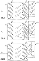
- the vane ring 270 is then moved such that the variable vanes 142b move through the throat regions 92 past the end row 90 into an assembled position axially between the end row 90 and a next row (shown at 94) of blades 40b from the end row 90.
- variable vanes 142b and the multi-row integrally bladed rotor drum 60 can be adapted to permit the axial assembly of the variable vanes 142b past the blades 40b into the assembled position.
- vanes often seal against a portion of a rotor.
- the seal includes a knife edge 271a provided or formed on the multi-row integrally bladed rotor drum 60 ( Figure 2 ), and the variable vanes 142b include honeycombs 271b on radially inner diameters.
- the honeycomb could be on the rotor and the knife edges on the vanes.
- a radial clearance gap is provided between the knife edge 271a and the honeycomb 271b to permit the honeycombs 271b of the variable vanes 142b to move into axial alignment with the knife edges 271a (or alternatively the knife edges to move into axial alignment with the honeycomb).
- the clearance gap can be at least as large as dimensional and assembly tolerances to ensure that there is no interference during assembly.
- the vane ring 270 is moved axially and circumferentially to navigate the variable vanes 142b through the throat regions 92, with no or little contact with the blades 40b.
- the axial and circumferential movement is represented at stepped lines 96.
- variable vanes 142b are pivoted about their radial axes to navigate through the throat regions 92 with no or little contact with the blades 40b.
- the pivoting movement is represented at lines 98.
- the variable vanes 142b be pivoted, in combination with also moving axially and circumferentially, to navigate through the throat regions 92.
- the blades 40b of at least one row of the multi-row integrally bladed rotor drum 60 are initially separate such that a full hoop vane ring 370 can be axially assembled over the multi-row integrally bladed rotor drum 60.
- the blades 40b of the second row are then secured to, or formed on, the multi-row integrally bladed rotor drum 60.
- the blades 40b can be pre-fabricated and then secured or, alternatively, fabricated in-situ on the multi-row integrally bladed rotor drum 60 using an additive fabrication technique.
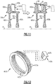
- Figure 12 illustrates another example vane assembly 470 for installing the row of compressor vanes 42b axially between the rows of the compressor blades 40b of the multi-row integrally bladed rotor drum 60.
- the vane assembly 470 is a continuous full hoop that includes an annular support 473 with a plurality of vane openings 473a arranged around the circumference thereof.
- the annular support 473 can be positioned axially between the rows of rotor blades 40b, and the vanes 42b can then be inserted radially through the vane openings 473a.
- the vanes 42b are vane multiplets that have two or more airfoils that are attached to a common platform 475. Each multiplet is assembled into the annular support 470.
- the vanes 42b can be individual vanes that are assembled into the annular support 470 individually.
- the vanes 42b are secured to the annular support 473 by mechanical fastener, bonded joint, or combination thereof.
- the mechanical joint can include a tab that extends from the vane 42b adjacent the annular support 473.
- the tab and annular support 473 can have an opening that receives a fastener there through.
- the bonded joint can be a braze joint or a weld joint around the perimeter of the vane 42b at the interface with the annular support 473.
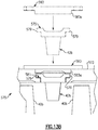
- Figures 13A and 13B illustrate another example vane assembly 570 for installing the row of compressor vanes 42b axially between the rows of the compressor blades 40b of the multi-row integrally bladed rotor drum 60.
- the vane assembly 570 is a continuous full hoop that includes an annular support 573 with at least one window 577 that opens radially outwards.
- the annular support 573 can be positioned axially between the rows of rotor blades 40b, and the vanes 42b can then be inserted radially through the window 577.
- the platforms 575 of the vanes 42b have opposed hooks 579 that engage a slot 581 at the inner diameter of the annular support 573.
- the slot 581 extends circumferentially around the inner diameter of the annular support 573.
- Each vane 42b is inserted through the window 577 and into the slot 581.
- the hooks 579 engage the slot 581 such that the vane 42b can then be slid circumferentially around the slot 581 to its final assembly position.
- a cover 583 is secured over the window 577.
- the cover 583 has a stop portion 583a that protrudes radially inwards in between adjacent vanes 42b.
- the stop 583a circumferentially locks the vanes 42b in place.
- the stop portion 583a can be a separate piece from the cover 583.
- Figure 14 illustrates another example gas turbine engine 120 that is similar to the engine 20.
- the case 148 is separable to permit a relatively large access work space 100 through the case 148 between an exterior of the case 148 and the core engine.
- the case 148 has a first section 148a and a second, hoop section 148b aft of the first section 148a.
- the second section 148b is axially moveable from the first section 148a to provide the access work space 100.
- the case 148 includes a track 102 on which the second section 148b is slidable.
- Lock members 104a/104b can be provided to selectively secure the first section 148a and the second section 148b together.
- the lock members 104a/104b include a latch, a V-groove arrangement, or the like, which also ensure axial alignment of the sections 148a/148b.
Landscapes
- Engineering & Computer Science (AREA)
- Mechanical Engineering (AREA)
- General Engineering & Computer Science (AREA)
- Chemical & Material Sciences (AREA)
- Combustion & Propulsion (AREA)
- Physics & Mathematics (AREA)
- Fluid Mechanics (AREA)
- Structures Of Non-Positive Displacement Pumps (AREA)
Description
- The present invention refers to a method of assembling a section of a gas turbine engine.
- A gas turbine engine typically includes a fan section, a compressor section, a combustor section and a turbine section. Air entering the compressor section is compressed and delivered into the combustion section where it is mixed with fuel and ignited to generate a high-speed exhaust gas flow. The high-speed exhaust gas flow expands through the turbine section to drive the compressor and the fan section. The compressor section typically includes low and high pressure compressors, and the turbine section includes low and high pressure turbines.
- The high pressure turbine drives the high pressure compressor through a high spool, and the low pressure turbine drives the low pressure compressor through a low spool. The fan section may also be driven by the low spool. A direct-drive gas turbine engine includes a fan section driven by the low spool, without a gear mechanism, such that the low pressure compressor, low pressure turbine and fan section rotate at a common speed.
-
US 2011/0223013 A1 discloses a reduced monobloc multistage drum of axial compressor. - From a first aspect there is provided a method for assembling a section of a gas turbine engine as recited in claim 1.
- In an embodiment, the plurality of vane arc segments have equivalent arc lengths.
- In a further embodiment of any of the foregoing embodiments, the plurality of vane arc segments have different arc lengths.
- A further embodiment of any of the foregoing embodiments includes providing a seal at an interface between two of the plurality of vane arc segments.
- In a further embodiment of any of the foregoing embodiments, each of the plurality of vane arc segments includes a plurality of vanes in a vane support structure.
- In a further embodiment of any of the foregoing embodiments, the multi-row rotor drum and the vane segments are in a high compressor section of a gas turbine engine.
- The various features and advantages of the present disclosure will become apparent to those skilled in the art from the following detailed description. The drawings that accompany the detailed description can be briefly described as follows.
-
Figure 1 illustrates an example gas turbine engine that has a direct-drive engine architecture. -
Figure 2 illustrates an example multi-row rotor drum of a low compressor section. -
Figure 3 illustrates an example split vane assembly. -
Figure 4 illustrates an overlapping joint of a split vane assembly according to the present invention; -
Figure 5 illustrates an example sealed joint of a split vanes assembly. -
Figure 6 illustrates a split vane assembly with arc segments that have end portions that are stronger than intermediate portions of the arc segments, according to the present invention; -
Figure 7 illustrates an example multi-row rotor drum that is assembled from two hub sections that are bonded together. -
Figure 8 illustrates an example of a vane ring that is assembled onto a multi-row rotor drum by sliding variable vanes through the throat regions between blades of an end row of the rotor. -
Figure 9 illustrates an example of a vane ring that is assembled onto a multi-row rotor drum by sliding variable vanes axially and circumferentially. -
Figure 10 illustrates an example of a vane ring that is assembled onto a multi-row rotor drum by pivoting variable vanes. -
Figure 11 illustrates an example vane ring that is assembled onto a multi-row integrally bladed rotor drum, where at least one row of blades is secured to, or fabricated in-situ on, the multi-row integrally bladed rotor drum. -
Figure 12 illustrates an example continuous hoop vane ring. -
Figure 13A illustrates another example continuous hoop vane ring. -
Figure 13B illustrates a cross-section of the continuous hoop vane ring ofFigure 13A after insertion of a vane. -
Figure 14 illustrates an example of a gas turbine engine with a case that has a first section and a second, hoop section aft of the first section. -
Figure 1 schematically illustrates a gas turbine engine 20 ("engine 20"). The engine 20 has a direct-drive engine architecture. Unlike a geared engine architecture that drives the fan through a gear mechanism to change the rotational speed of the fan relative to the driving portion of the turbine, a direct-drive engine architecture drives the fan without such a gear mechanism such that the fan rotates at the same speed as the driving portion of the turbine. - The engine 20 is a two-spool arrangement that generally includes a
fan section 22, acompressor section 24, acombustor section 26, and aturbine section 28. In this example, these sections are arranged serially along engine central axis A with respect to flow through the engine 20, although the examples herein may also be applicable to reverse-flow arrangements and other multi-spool arrangements, such as three-spool arrangements. - The engine 20 includes a first (or low) spool 30 and a second (or high)
spool 32 mounted onbearing systems 38 for concentric rotation about the engine central axis A relative to an enginestatic structure 36. Although thebearing systems 38 are shown at various locations, these locations can vary as appropriate to the engine design, and fewer oradditional bearing systems 38 may be provided. The first spool 30 may be referred to as a low speed spool and thesecond spool 32 may be referred to as a high speed spool, relative to the speed of the low speed spool. - The
compressor section 24 includes alow compressor section 24a and ahigh compressor section 24b, and theturbine section 28 includes alow turbine section 28a and ahigh turbine section 28b. Thelow compressor section 24a may also be referred to as a low pressure compressor and thehigh compressor section 24b may be referred to as a high pressure compressor, relative to pressure in the low pressure compressor. Likewise, thelow turbine section 28a may also be referred to as a low pressure turbine and thehigh turbine section 28b may be referred to as a high pressure turbine, relative to pressure in the low pressure turbine. - The
low compressor section 24a and thehigh compressor section 24b include, respectively, rows ofrotatable compressor blades static compressor vanes 42a and 42b. A row of compressor vanes and an adjacent row of compressor blades are a compressor stage. - The
low turbine section 28a and thehigh turbine section 28b include, respectively, rows ofrotatable turbine blades static turbine vanes 46a and 46b. A row of turbine vanes and an adjacent row of turbine blades are a turbine stage. In this example, thelow turbine section 28a has four stages. In other examples, thelow turbine section 28a may have three or fewer stages. In other examples, thelow turbine section 28a may have more than four stages such as, for example, five, six, or seven stages. - The
fan section 22 includes at least one row offan blades 22a. Acase 48 extends around thefan section 22 and bounds an outer periphery of abypass passage 50. Thefan blades 22a are located generally at the inlet of thebypass passage 50. One or more rows ofguide vanes 52 can be provided downstream from thefan blades 22a. The guide vanes 52 extend between thecase 48 and thestatic structure 36. - The
combustion section 26 includes acombustor 54. In this example, thecombustor 54 is arranged axially between thehigh compressor section 24b and thehigh turbine section 28b. - The first spool 30 directly couples the
low turbine section 28a with thelow compressor section 24a and thefan section 22. Thesecond spool 32 couples thehigh turbine section 28b with thehigh compressor section 24b. Since there is no gear mechanism in the interconnection between thelow turbine section 28a and thefan section 22, the engine 20 is a direct-drive engine architecture, and thefan section 22 will rotate at the same rotational speed as thelow turbine section 28a. - The
compressor section 24, thecombustor section 26, and theturbine section 28 form a core engine, which drives thefan section 22. Thecompressor section 24 drives core air C along a core flow path through thelow compressor section 24a and then thehigh compressor section 24b. Compressed air from thehigh compressor section 24b is mixed with fuel and burned in thecombustor 54 to generate an exhaust gas stream. The exhaust gas stream is expanded through thehigh turbine section 28b and then thelow turbine section 28a. The expansion over thehigh turbine section 28b rotationally drives thesecond spool 32 to thus drive thehigh compressor section 24b. The expansion over thelow turbine section 28a rotationally drives the first spool 30 to thus drive thelow compressor section 24a and thefan section 22. The rotation of thefan section 22 drives bypass air B through the bypass passage 50 (to provide a significant amount of the thrust of the engine 20) and core air C to the low compressor section 42a. - One characteristic of a turbofan engine is the bypass ratio of the turbofan engine. The bypass ratio is the ratio of the amount of air that passes through the
bypass passage 50 as bypass air B to the amount of air that passes through the core engine as core air C at a given performance point. Typically a direct drive turbofan engine will not be able to exceed a bypass ratio of about 8 due to engine performance limitations. However, according to an embodiment, the core engine includes a bypass ratio of 8.5 - 11 even without a gear and with an engine has a thrust rating equal to or less than 40,000 pounds (18,180 kg). In one further embodiment, the thrust rating is from 30,000 pounds (13,640 kg) to 40,000 pounds (18,180 kg), and the overall pressure ratio ("OPR") is approximately 40 to approximately 50. The OPR is the ratio of stagnation pressure at the inlet of thefan section 22, such as at P1 inFigure 1 , to the stagnation pressure at the outlet of thehigh compressor section 24b, such as at P2 inFigure 1 . The performance point for determining the overall pressure ratios herein is the flight condition at the top of climb prior to leveling off for cruise flight condition. The performance point for determining the bypass ratios herein is a particular flight condition -- typically cruise at about 0.8 Mach and about 35,000 feet (10,668 m). The flight condition of 0.8 Mach and 35,000 ft. (10,668 m), with the engine at its best fuel consumption - also known as "bucket cruise Thrust Specific Fuel Consumption ('TSFC')" - is the industry standard parameter of mass of fuel being burned divided by force of thrust the engine produces at that minimum point. - In a further example, the fan section 22 (at the root of the
fan blades 22a), thelow compressor section 24a and thehigh compressor section 24b together have an OPR of approximately 40 to approximately 60 In a further embodiment, enhanced performance can be achieved by including a first row ofturbine blades 46b of thehigh turbine section 28b that has an operating temperature of approximately 2700°F to approximately 3000°F (approximately 1482°C to approximately 1649°C) at maximum takeoff thrust, and with an engine that has a thrust rating equal to or less than 40,000 pounds (18,180 kg). In one further embodiment, the thrust rating is from 30,000 pounds to 40,000 pounds (13,640 kg to 18,180 kg), and the OPR is approximately 40 to approximately 50. In another example embodiment, the bypass ratio is greater than 4 and the OPR is greater than 40, and in one additional example embodiment the bypass ratio is 8.5-11 and the OPR is greater than 55. - In a further example, the row of
blades 22a of thefan section 22 have a fan diameter, Dfan, thehigh compressor section 24b has a final compressor blade row prior to thecombustor section 26 that has a compressor diameter, Dcomp, and the stages of thelow turbine section 28a have a maximum diameter, Dturb. The fan diameter, the compressor diameter, and the maximum diameter of thelow turbine section 28a have an interdependence represented by a scalable ratio Dfan/Dcomp from 3.5 to 5.0 and a scalable ratio Dfan/Dturb from 1.4 to 1.8, and the fan diameter is at least 68 inches. The interdependence is such that the value of any one of the fan diameter, the compressor diameter, and the maximum diameter depends on the values of the other two through the above ratios. -
Figure 2 illustrates selected portions of a further example of thehigh compressor section 24b. In this example, thehigh compressor section 24b includes a multi-row integrally bladedrotor drum 60 that is formed of a single-piece body 62. In one example, instead of bonded joints or mechanical joints that are used to secure several hub pieces together, the single-piece body 62 includes no joints. For instance, the single-piece body 62 is a single, continuous piece of material. In other examples, the multi-row integrally bladedrotor drum 60 includes one or more bonded joints that serve solely, or at least primarily, to hold the multi-row integrally bladedrotor drum 60 together as a unit. In this case, the multi-row integrally bladedrotor drum 60 may include one or more mechanical joints that supplement the one or more bonded joints. A bonded joint may be a joint that is secured by an adhesive, by pressure, by heat, or a combination thereof, such that there is a distinct boundary or discontinuity between the bonded portions that is at least microscopically discernible. Weld and braze joints are examples of bonded, metallurgical joints. - The multi-row integrally bladed
rotor drum 60 presents a challenge to assembly of thehigh compressor section 24b. With single rotors, a continuous hoop vane assembly can be assembled axially between rotors. However, the single-piece body 62 may not permit this assembly approach because the blades would interfere with the vanes of the vane assembly during installation; therefore, a different assembly methodology that meets this challenge is needed. It is to be understood that the examples herein are also applicable to a turbine section that includes a multi-row rotor drum. Further, assembly can include assembling sections of thehigh compressor section 24b into the engine 20 to form thehigh compressor section 24b in the engine 20, or assembling the sections to separately form thehigh compressor section 24b and then assembling thehigh compressor section 24b into the engine 20. - In one example, the
compressor vanes 42b that are axially between the rows of thecompressor blades 40b of the multi-row integrally bladedrotor drum 60 are in asplit vane assembly 70, shown inFigure 3 . Thesplit vane assembly 70 includes two 180°arc segments arc segments 70a/70b can each be inserted in a radial direction (see "R"Figure 2 ) into an assembled position between the rows of thecompressor blades 40b to provide the row ofcompressor vanes 42b. In one modified example, thearc segments vane assembly 70 could have three or more arc segments, which may have equal or unequal arc lengths, or a combination thereof. - Once in the assembled position, the circumferential ends of the
arc segments 70a/70b meet at joints or interfaces. These joints or interfaces could be locations of weakness and/or locations at which core air could escape.Figure 4 illustrates an overlapping joint, according to the invention. In this embodiment, thearc segments 70a/70b include, respectively,tabs 74a/74b that overlap with respect to the radial direction R. The overlapping joint 72 can serve any or all of several functions, including but not limited to, facilitating alignment of thearc segments 70a/70b, locking thearc segments 70a/70b, and providing labyrinth sealing at the interface. Optionally, one or more alignment pins 75 can also be used to facilitate axial alignment. -
Figure 5 illustrates another example joint 172. In this disclosure, like reference numerals designate like elements where appropriate and reference numerals with the addition of one-hundred or multiples thereof designate modified elements that are understood to incorporate the same features and benefits of the corresponding elements. In this example, thearc segments 170a/170b include, respectively,slots 176a/176b. Theslots 170a/170b cooperatively retain acircumferential seal element 178 in the interface of the joint 172, to reduce the potential for the escape of core air. In further examples, at least portions of the interfaces can be non-mechanically bonded, such as by weld or braze, to provide sealing. Optionally, one or more alignment pins 175 can also be used to facilitate axial alignment. -
Figure 6 illustrates a further embodiment of the invention in whicharc segments 270a/270b includeend portions 280 that are stronger thanintermediate portions 282 of thearc segments 270a/270b. In one example falling outside the wording of the claims, theend portions 280 are made stronger by adding mechanical features, such as increased thickness ofvanes 42b in theend portions 280 relative to the other vanes in thearc segment 270a/270b or features in theend portions 280 that allow for structural bonding of theend portions 280 in addition to the arc segments, as described inFigure 4 and 5 . In accordance with the claims, theend portions 280 are made stronger by using a different, stronger material for the end portions than theintermediate portions 282. Thestronger end portions 280 resist deflection of the full vane ring at the joints between thearc segments 270a/270b, which may reduce "ovalization" during operational loading. -
Figure 7 illustrates another example multi-row integrally bladedrotor drum 160 that has asingle piece body 162. In this example, thesingle piece body 162 includes one or more bonded joints, such as at Ji. A bonded joint may be a joint that is secured by an adhesive, by pressure, by heat, or a combination thereof, such that there is a distinct boundary or discontinuity between the bonded portions that is at least microscopically discernible. For example, thesingle piece body 162 can include a first,forward hub 162a and a second,aft hub 162b that are bonded together at bonded joint Ji. Eachhub 162a/162b includes a row of thecompressor blades 40b which are bonded to or machined with eachhub 162a/162b, with the row ofcompressor vanes 42b axially there between. Thus, thefirst hub 162a can be assembled, followed by axial assembly of a vane assembly, followed by assembly of thesecond hub 162b, which is then bonded in joint Ji to thefirst hub 162a. In this regard, the bonded joint permits the use of an axial assembly approach. - As also shown in
Figure 7 , thecompressor vanes 42b can be assembled by moving avane ring 170 with thecompressor vanes 42b into alignment with thefirst hub 162a such that the row ofvanes 42b is adjacent the first row ofblades 40b. In a further embodiment, thevane ring 170 is a continuous full hoop. Thesecond rotor hub 162b is then moved into alignment with thevane ring 170 such that the second row ofblades 40b is adjacent the row ofvanes 42b and the row ofvanes 42b is axially between the first and second rows ofblades 40b. Thefirst hub 162a and thesecond hub 162b are then non-mechanically bonded at bonded joint Ji. In this regard, the bonded joint Ji permits the use of an axial assembly approach. -
Figure 8 illustrates another example in whichvanes 142b ofvane ring 270 are variable vanes, to permit axial assembly of thevane ring 270 onto the multi-row integrally bladedrotor drum 60. As can be appreciated, only a few of thevariable vanes 142b are shown, to demonstrate the assembly. It is to be understood that thevane ring 270 is a full hoop with thevariable vanes 142b circumferentially-spaced there around. Thevariable vanes 142b can be pivoted about their individual radial axis. In some embodiments, thevariable vanes 142b are interconnected with a common actuation mechanism such that thevariable vanes 142b are moveable in unison. For instance, a unison ring can be provided to link thevariable vanes 142b such that rotation of the unison ring causes eachvariable vane 142b to pivot about its own radial axis. In other embodiments, eachvariable vane 142b can be moved independently of the othervariable vanes 142b. Further, thevariable vanes 142b can be moved in an automated fashion using a powered actuator, or thevariable vanes 142b can be moved manually or using a tool, such as a torque wrench or other device. - In this embodiment, the multi-row integrally bladed
rotor drum 60 includes at its axial end anend row 90 ofblades 40b. Theblades 40b are circumferentially spaced-apart byrespective throat regions 92. To assemble thevane ring 270 onto the multi-row integrally bladedrotor drum 60, eachvariable vane 142b is aligned with acorresponding throat region 92 of theend row 90. For instance, the chords or thevariable vanes 142b are aligned relative to thethroat regions 92. Thevane ring 270 is then moved such that thevariable vanes 142b move through thethroat regions 92 past theend row 90 into an assembled position axially between theend row 90 and a next row (shown at 94) ofblades 40b from theend row 90. - In further embodiments, the design of the
variable vanes 142b and the multi-row integrally bladedrotor drum 60 can be adapted to permit the axial assembly of thevariable vanes 142b past theblades 40b into the assembled position. For instance, vanes often seal against a portion of a rotor. In one example, the seal includes aknife edge 271a provided or formed on the multi-row integrally bladed rotor drum 60 (Figure 2 ), and thevariable vanes 142b includehoneycombs 271b on radially inner diameters. Alternatively, the honeycomb could be on the rotor and the knife edges on the vanes. A radial clearance gap is provided between theknife edge 271a and thehoneycomb 271b to permit thehoneycombs 271b of thevariable vanes 142b to move into axial alignment with the knife edges 271a (or alternatively the knife edges to move into axial alignment with the honeycomb). The clearance gap can be at least as large as dimensional and assembly tolerances to ensure that there is no interference during assembly. - In another embodiment shown in
Figure 9 , thevane ring 270 is moved axially and circumferentially to navigate thevariable vanes 142b through thethroat regions 92, with no or little contact with theblades 40b. The axial and circumferential movement is represented at steppedlines 96. - In another example shown in
Figure 10 , thevariable vanes 142b are pivoted about their radial axes to navigate through thethroat regions 92 with no or little contact with theblades 40b. The pivoting movement is represented atlines 98. Of course, it is also contemplated that thevariable vanes 142b be pivoted, in combination with also moving axially and circumferentially, to navigate through thethroat regions 92. - In another example shown in
Figure 11 , theblades 40b of at least one row of the multi-row integrally bladedrotor drum 60 are initially separate such that a fullhoop vane ring 370 can be axially assembled over the multi-row integrally bladedrotor drum 60. Theblades 40b of the second row are then secured to, or formed on, the multi-row integrally bladedrotor drum 60. In this regard, theblades 40b can be pre-fabricated and then secured or, alternatively, fabricated in-situ on the multi-row integrally bladedrotor drum 60 using an additive fabrication technique. -
Figure 12 illustrates anotherexample vane assembly 470 for installing the row ofcompressor vanes 42b axially between the rows of thecompressor blades 40b of the multi-row integrally bladedrotor drum 60. In this example, thevane assembly 470 is a continuous full hoop that includes anannular support 473 with a plurality ofvane openings 473a arranged around the circumference thereof. Theannular support 473 can be positioned axially between the rows ofrotor blades 40b, and thevanes 42b can then be inserted radially through thevane openings 473a. In this example, thevanes 42b are vane multiplets that have two or more airfoils that are attached to acommon platform 475. Each multiplet is assembled into theannular support 470. Alternatively, thevanes 42b can be individual vanes that are assembled into theannular support 470 individually. - The
vanes 42b are secured to theannular support 473 by mechanical fastener, bonded joint, or combination thereof. If mechanical, the mechanical joint can include a tab that extends from thevane 42b adjacent theannular support 473. The tab andannular support 473 can have an opening that receives a fastener there through. If bonded, the bonded joint can be a braze joint or a weld joint around the perimeter of thevane 42b at the interface with theannular support 473. -
Figures 13A and13B illustrate anotherexample vane assembly 570 for installing the row ofcompressor vanes 42b axially between the rows of thecompressor blades 40b of the multi-row integrally bladedrotor drum 60. In this example, thevane assembly 570 is a continuous full hoop that includes anannular support 573 with at least onewindow 577 that opens radially outwards. Theannular support 573 can be positioned axially between the rows ofrotor blades 40b, and thevanes 42b can then be inserted radially through thewindow 577. - The
platforms 575 of thevanes 42b have opposedhooks 579 that engage aslot 581 at the inner diameter of theannular support 573. Theslot 581 extends circumferentially around the inner diameter of theannular support 573. Eachvane 42b is inserted through thewindow 577 and into theslot 581. Thehooks 579 engage theslot 581 such that thevane 42b can then be slid circumferentially around theslot 581 to its final assembly position. After all of thevanes 42b have been inserted and slid to final position, acover 583 is secured over thewindow 577. Thecover 583 has astop portion 583a that protrudes radially inwards in betweenadjacent vanes 42b. Thestop 583a circumferentially locks thevanes 42b in place. Alternatively, thestop portion 583a can be a separate piece from thecover 583. -
Figure 14 illustrates another examplegas turbine engine 120 that is similar to the engine 20. In this example, the case 148 is separable to permit a relatively largeaccess work space 100 through the case 148 between an exterior of the case 148 and the core engine. The case 148 has afirst section 148a and a second,hoop section 148b aft of thefirst section 148a. Thesecond section 148b is axially moveable from thefirst section 148a to provide theaccess work space 100. In one example, the case 148 includes atrack 102 on which thesecond section 148b is slidable.Lock members 104a/104b can be provided to selectively secure thefirst section 148a and thesecond section 148b together. For example, thelock members 104a/104b include a latch, a V-groove arrangement, or the like, which also ensure axial alignment of thesections 148a/148b. - The preceding description is exemplary rather than limiting in nature. Variations and modifications to the disclosed examples may become apparent to those skilled in the art that do not necessarily depart from this disclosure. The scope of legal protection given to this disclosure can only be determined by studying the following claims.
Claims (6)
- A method for assembling a section of a gas turbine engine (20; 120), the method comprising:inserting a plurality of vane arc segments (70a,b;170a,b;270a,b) in a radial direction into an assembled position that is axially between two rows of blades (40a,b) of a multi-row rotor drum (60; 160), the multi-row rotor drum (160) being formed of a single-piece body (62; 162) that has at least two rows of blades (40a,b) about a central axis (A);providing overlapping joints (72; 172) at circumferential ends of each of the plurality of vane arc segments (70a...270b); andmaking circumferential end portions (280) of the plurality of vane arc segments (70a... 270b) stronger than circumferential intermediate portions (282) of the plurality of vane arc segments (70a... 270b) by using a different, stronger, material for the circumferential end portions (280) than the material used for the circumferential intermediate portions (282) to resist deflection at the overlapping joints (72; 172).
- The method as recited in claim 1, wherein the plurality of vane arc segments (70a...270b) have equivalent arc lengths.
- The method as recited in claim 1, wherein the plurality of vane arc segments (70a...270b) have different arc lengths.
- The method as recited in any preceding claim, further comprising providing a seal (178) at an interface between two of the plurality of vane arc segments (170a,b).
- The method as recited in any preceding claim, wherein each of the plurality of vane arc segments (70a... 270b) includes a plurality of vanes (42b) in a vane support structure (473;573).
- The method as recited in any preceding claim, wherein the multi-row rotor drum (60; 160) and the vane segments (70a... 270b) are in a high compressor section (24b) of a gas turbine engine (20; 120).
Applications Claiming Priority (1)
| Application Number | Priority Date | Filing Date | Title |
|---|---|---|---|
| US14/607,301 US9333603B1 (en) | 2015-01-28 | 2015-01-28 | Method of assembling gas turbine engine section |
Publications (2)
| Publication Number | Publication Date |
|---|---|
| EP3051069A1 EP3051069A1 (en) | 2016-08-03 |
| EP3051069B1 true EP3051069B1 (en) | 2021-08-25 |
Family
ID=55262725
Family Applications (1)
| Application Number | Title | Priority Date | Filing Date |
|---|---|---|---|
| EP16152936.7A Active EP3051069B1 (en) | 2015-01-28 | 2016-01-27 | Method of assembling of a gas turbine engine section |
Country Status (2)
| Country | Link |
|---|---|
| US (2) | US9333603B1 (en) |
| EP (1) | EP3051069B1 (en) |
Families Citing this family (10)
| Publication number | Priority date | Publication date | Assignee | Title |
|---|---|---|---|---|
| FR3020658B1 (en) * | 2014-04-30 | 2020-05-15 | Safran Aircraft Engines | LUBRICATION OIL RECOVERY HOOD FOR TURBOMACHINE EQUIPMENT |
| US10125788B2 (en) * | 2016-01-08 | 2018-11-13 | General Electric Company | Ceramic tile fan blade containment |
| US10495108B2 (en) * | 2017-01-31 | 2019-12-03 | Honeywell International Inc. | Variable vane devices containing rotationally-driven translating vane structures and methods for the production thereof |
| EP3447244A1 (en) * | 2017-08-23 | 2019-02-27 | Siemens Aktiengesellschaft | Turbine rotor assembly with lap joints between the rotor discs for torque transmission |
| US10711629B2 (en) | 2017-09-20 | 2020-07-14 | Generl Electric Company | Method of clearance control for an interdigitated turbine engine |
| PL431184A1 (en) * | 2019-09-17 | 2021-03-22 | General Electric Company Polska Spółka Z Ograniczoną Odpowiedzialnością | Turboshaft engine set |
| US11428160B2 (en) | 2020-12-31 | 2022-08-30 | General Electric Company | Gas turbine engine with interdigitated turbine and gear assembly |
| EP4059649B1 (en) * | 2021-03-16 | 2025-09-17 | Newfrey LLC | Welding gun and method for monitoring a welding process |
| FR3137122B1 (en) * | 2022-06-22 | 2024-06-21 | Safran Aircraft Engines | Bladed assembly with inter-platform connection by friction member |
| CN115870699B (en) * | 2022-10-25 | 2024-11-12 | 杭州汽轮动力集团股份有限公司 | Gas turbine compressor stationary blade ring welding positioning fixture and related welding method |
Citations (1)
| Publication number | Priority date | Publication date | Assignee | Title |
|---|---|---|---|---|
| US5564897A (en) * | 1992-04-01 | 1996-10-15 | Abb Stal Ab | Axial turbo-machine assembly with multiple guide vane ring sectors and a method of mounting thereof |
Family Cites Families (49)
| Publication number | Priority date | Publication date | Assignee | Title |
|---|---|---|---|---|
| US3355890A (en) | 1965-06-09 | 1967-12-05 | Gen Electric | Cruise fan powerplant |
| US3287906A (en) | 1965-07-20 | 1966-11-29 | Gen Motors Corp | Cooled gas turbine vanes |
| GB1350431A (en) | 1971-01-08 | 1974-04-18 | Secr Defence | Gearing |
| US3887976A (en) * | 1971-02-03 | 1975-06-10 | J Rodger Sheilds | Stator blade assembly for turbo machines |
| US3892358A (en) | 1971-03-17 | 1975-07-01 | Gen Electric | Nozzle seal |
| US4010608A (en) | 1975-06-16 | 1977-03-08 | General Electric Company | Split fan work gas turbine engine |
| US4130872A (en) | 1975-10-10 | 1978-12-19 | The United States Of America As Represented By The Secretary Of The Air Force | Method and system of controlling a jet engine for avoiding engine surge |
| GB1516041A (en) | 1977-02-14 | 1978-06-28 | Secr Defence | Multistage axial flow compressor stators |
| GB2041090A (en) | 1979-01-31 | 1980-09-03 | Rolls Royce | By-pass gas turbine engines |
| GB2171150B (en) * | 1985-02-12 | 1989-07-26 | Rolls Royce Plc | Bladed rotor assembly for a turbomachine |
| FR2582720B1 (en) * | 1985-05-29 | 1989-06-02 | Snecma | PROCESS FOR PRODUCING A TURBOMACHINE BLADE PIVOT AND A STATOR BLADE COMPRISING SAME |
| US4790133A (en) | 1986-08-29 | 1988-12-13 | General Electric Company | High bypass ratio counterrotating turbofan engine |
| US5035573A (en) * | 1990-03-21 | 1991-07-30 | General Electric Company | Blade tip clearance control apparatus with shroud segment position adjustment by unison ring movement |
| US5127797A (en) * | 1990-09-12 | 1992-07-07 | United Technologies Corporation | Compressor case attachment means |
| US5203162A (en) | 1990-09-12 | 1993-04-20 | United Technologies Corporation | Compressor bleed manifold for a gas turbine engine |
| EP0503697B1 (en) | 1991-03-11 | 1995-06-21 | General Motors Corporation | Method for joining individual turbine blades within a multiple-property turbine rotor |
| US5447411A (en) | 1993-06-10 | 1995-09-05 | Martin Marietta Corporation | Light weight fan blade containment system |
| US5524847A (en) | 1993-09-07 | 1996-06-11 | United Technologies Corporation | Nacelle and mounting arrangement for an aircraft engine |
| US5433674A (en) | 1994-04-12 | 1995-07-18 | United Technologies Corporation | Coupling system for a planetary gear train |
| US5778659A (en) | 1994-10-20 | 1998-07-14 | United Technologies Corporation | Variable area fan exhaust nozzle having mechanically separate sleeve and thrust reverser actuation systems |
| EP0839285B1 (en) | 1994-12-14 | 2001-07-18 | United Technologies Corporation | Compressor stall and surge control using airflow asymmetry measruement |
| US5569018A (en) * | 1995-03-06 | 1996-10-29 | General Electric Company | Technique to prevent or divert cracks |
| US5857836A (en) | 1996-09-10 | 1999-01-12 | Aerodyne Research, Inc. | Evaporatively cooled rotor for a gas turbine engine |
| US5975841A (en) | 1997-10-03 | 1999-11-02 | Thermal Corp. | Heat pipe cooling for turbine stators |
| US6223616B1 (en) | 1999-12-22 | 2001-05-01 | United Technologies Corporation | Star gear system with lubrication circuit and lubrication method therefor |
| US6318070B1 (en) | 2000-03-03 | 2001-11-20 | United Technologies Corporation | Variable area nozzle for gas turbine engines driven by shape memory alloy actuators |
| US7651319B2 (en) * | 2002-02-22 | 2010-01-26 | Drs Power Technology Inc. | Compressor stator vane |
| US6814541B2 (en) | 2002-10-07 | 2004-11-09 | General Electric Company | Jet aircraft fan case containment design |
| US7021042B2 (en) | 2002-12-13 | 2006-04-04 | United Technologies Corporation | Geartrain coupling for a turbofan engine |
| CN100419220C (en) * | 2003-05-07 | 2008-09-17 | 斯奈克玛马达公司 | Turbine stator and method of assembly and disassembly thereof |
| US7185484B2 (en) | 2004-08-11 | 2007-03-06 | General Electric Company | Methods and apparatus for assembling a gas turbine engine |
| WO2007038674A1 (en) | 2005-09-28 | 2007-04-05 | Entrotech Composites, Llc | Braid-reinforced composites and processes for their preparation |
| US7591754B2 (en) | 2006-03-22 | 2009-09-22 | United Technologies Corporation | Epicyclic gear train integral sun gear coupling design |
| GB2436597A (en) * | 2006-03-27 | 2007-10-03 | Alstom Technology Ltd | Turbine blade and diaphragm |
| US7914255B2 (en) * | 2006-04-21 | 2011-03-29 | General Electric Company | Apparatus and method of diaphragm assembly |
| US7926260B2 (en) | 2006-07-05 | 2011-04-19 | United Technologies Corporation | Flexible shaft for gas turbine engine |
| US8017188B2 (en) | 2007-04-17 | 2011-09-13 | General Electric Company | Methods of making articles having toughened and untoughened regions |
| US8007229B2 (en) * | 2007-05-24 | 2011-08-30 | United Technologies Corporation | Variable area turbine vane arrangement |
| US20140157757A1 (en) | 2007-09-21 | 2014-06-12 | United Technologies Corporation | Gas turbine engine compressor arrangement |
| US8205432B2 (en) | 2007-10-03 | 2012-06-26 | United Technologies Corporation | Epicyclic gear train for turbo fan engine |
| US9273563B2 (en) | 2007-12-28 | 2016-03-01 | United Technologies Corporation | Integrally bladed rotor with slotted outer rim |
| US8092165B2 (en) * | 2008-01-21 | 2012-01-10 | Pratt & Whitney Canada Corp. | HP segment vanes |
| US8695920B2 (en) | 2008-06-02 | 2014-04-15 | United Technologies Corporation | Gas turbine engine with low stage count low pressure turbine |
| US20140174056A1 (en) | 2008-06-02 | 2014-06-26 | United Technologies Corporation | Gas turbine engine with low stage count low pressure turbine |
| US8511982B2 (en) * | 2008-11-24 | 2013-08-20 | Alstom Technology Ltd. | Compressor vane diaphragm |
| US8191352B2 (en) * | 2008-12-19 | 2012-06-05 | General Electric Company | Geared differential speed counter-rotatable low pressure turbine |
| US8172716B2 (en) | 2009-06-25 | 2012-05-08 | United Technologies Corporation | Epicyclic gear system with superfinished journal bearing |
| EP2369136B1 (en) * | 2010-03-12 | 2012-12-19 | Techspace Aero S.A. | Weight-reduced single-piece multi-stage drum of an axial flow compressor |
| US9534608B2 (en) * | 2012-02-17 | 2017-01-03 | Embry-Riddle Aeronautical University, Inc. | Multi-stage axial compressor with counter-rotation |
-
2015
- 2015-01-28 US US14/607,301 patent/US9333603B1/en active Active
-
2016
- 2016-01-27 EP EP16152936.7A patent/EP3051069B1/en active Active
- 2016-03-03 US US15/059,805 patent/US9909457B2/en active Active
Patent Citations (1)
| Publication number | Priority date | Publication date | Assignee | Title |
|---|---|---|---|---|
| US5564897A (en) * | 1992-04-01 | 1996-10-15 | Abb Stal Ab | Axial turbo-machine assembly with multiple guide vane ring sectors and a method of mounting thereof |
Also Published As
| Publication number | Publication date |
|---|---|
| US9909457B2 (en) | 2018-03-06 |
| EP3051069A1 (en) | 2016-08-03 |
| US9333603B1 (en) | 2016-05-10 |
| US20160215653A1 (en) | 2016-07-28 |
Similar Documents
| Publication | Publication Date | Title |
|---|---|---|
| EP3051069B1 (en) | Method of assembling of a gas turbine engine section | |
| EP3734018B1 (en) | Seal for a gas turbine engine component and corresponding method | |
| EP3663528B1 (en) | Gas turbine engine arc segments with arced walls | |
| EP3594452B1 (en) | Seal segment for a gas turbine engine | |
| EP1531236B1 (en) | Compressor housing with bleed apertures of a gas turbine engine | |
| US20100247293A1 (en) | Variable area turbine vane arrangement | |
| EP3653915B1 (en) | Seal disassembly aid | |
| EP3039252B1 (en) | Variable vane bushing | |
| EP3067541B1 (en) | Geared turbine engine | |
| EP3190266B1 (en) | Gas turbine engine comprising a rotor hub seal | |
| EP3056685B1 (en) | Stator vane with platform having sloped face | |
| EP3822459B1 (en) | Blade outer air seal including cooling trench | |
| EP4219907B1 (en) | Combustor mounting structures for gas turbine engines | |
| EP3450692B1 (en) | Seal assembly for the interface between combustor and vane | |
| EP3282101B1 (en) | Shim for gas turbine engine | |
| EP3800378B1 (en) | Stiffening member for epicyclical gear system housing assembly | |
| EP3667048B1 (en) | Planet carrier and method of assembling of a planet carrier | |
| EP2971690B1 (en) | Interlocking rotor assembly with thermal shield | |
| EP3623587B1 (en) | Airfoil assembly for a gas turbine engine | |
| EP2995778B1 (en) | Method and assembly for reducing secondary heat in a gas turbine engine | |
| EP3000966B1 (en) | Method and assembly for reducing secondary heat in a gas turbine engine | |
| US11021970B2 (en) | Turbomachine with alternatingly spaced rotor blades | |
| EP2961930B1 (en) | Edge treatment for blade outer air seal segment | |
| EP2961964B1 (en) | Gas turbine engine component and corresponding method of manufacturing an aperture | |
| EP2986823B1 (en) | Airfoil component |
Legal Events
| Date | Code | Title | Description |
|---|---|---|---|
| PUAI | Public reference made under article 153(3) epc to a published international application that has entered the european phase |
Free format text: ORIGINAL CODE: 0009012 |
|
| AK | Designated contracting states |
Kind code of ref document: A1 Designated state(s): AL AT BE BG CH CY CZ DE DK EE ES FI FR GB GR HR HU IE IS IT LI LT LU LV MC MK MT NL NO PL PT RO RS SE SI SK SM TR |
|
| AX | Request for extension of the european patent |
Extension state: BA ME |
|
| RAP1 | Party data changed (applicant data changed or rights of an application transferred) |
Owner name: UNITED TECHNOLOGIES CORPORATION |
|
| STAA | Information on the status of an ep patent application or granted ep patent |
Free format text: STATUS: REQUEST FOR EXAMINATION WAS MADE |
|
| 17P | Request for examination filed |
Effective date: 20170203 |
|
| RBV | Designated contracting states (corrected) |
Designated state(s): AL AT BE BG CH CY CZ DE DK EE ES FI FR GB GR HR HU IE IS IT LI LT LU LV MC MK MT NL NO PL PT RO RS SE SI SK SM TR |
|
| STAA | Information on the status of an ep patent application or granted ep patent |
Free format text: STATUS: EXAMINATION IS IN PROGRESS |
|
| 17Q | First examination report despatched |
Effective date: 20181030 |
|
| GRAP | Despatch of communication of intention to grant a patent |
Free format text: ORIGINAL CODE: EPIDOSNIGR1 |
|
| STAA | Information on the status of an ep patent application or granted ep patent |
Free format text: STATUS: GRANT OF PATENT IS INTENDED |
|
| RAP1 | Party data changed (applicant data changed or rights of an application transferred) |
Owner name: RAYTHEON TECHNOLOGIES CORPORATION |
|
| INTG | Intention to grant announced |
Effective date: 20210311 |
|
| GRAS | Grant fee paid |
Free format text: ORIGINAL CODE: EPIDOSNIGR3 |
|
| GRAA | (expected) grant |
Free format text: ORIGINAL CODE: 0009210 |
|
| STAA | Information on the status of an ep patent application or granted ep patent |
Free format text: STATUS: THE PATENT HAS BEEN GRANTED |
|
| AK | Designated contracting states |
Kind code of ref document: B1 Designated state(s): AL AT BE BG CH CY CZ DE DK EE ES FI FR GB GR HR HU IE IS IT LI LT LU LV MC MK MT NL NO PL PT RO RS SE SI SK SM TR |
|
| REG | Reference to a national code |
Ref country code: CH Ref legal event code: EP |
|
| REG | Reference to a national code |
Ref country code: IE Ref legal event code: FG4D Ref country code: AT Ref legal event code: REF Ref document number: 1423987 Country of ref document: AT Kind code of ref document: T Effective date: 20210915 |
|
| REG | Reference to a national code |
Ref country code: DE Ref legal event code: R096 Ref document number: 602016062600 Country of ref document: DE |
|
| REG | Reference to a national code |
Ref country code: LT Ref legal event code: MG9D |
|
| REG | Reference to a national code |
Ref country code: NL Ref legal event code: MP Effective date: 20210825 |
|
| REG | Reference to a national code |
Ref country code: AT Ref legal event code: MK05 Ref document number: 1423987 Country of ref document: AT Kind code of ref document: T Effective date: 20210825 |
|
| PG25 | Lapsed in a contracting state [announced via postgrant information from national office to epo] |
Ref country code: LT Free format text: LAPSE BECAUSE OF FAILURE TO SUBMIT A TRANSLATION OF THE DESCRIPTION OR TO PAY THE FEE WITHIN THE PRESCRIBED TIME-LIMIT Effective date: 20210825 Ref country code: BG Free format text: LAPSE BECAUSE OF FAILURE TO SUBMIT A TRANSLATION OF THE DESCRIPTION OR TO PAY THE FEE WITHIN THE PRESCRIBED TIME-LIMIT Effective date: 20211125 Ref country code: AT Free format text: LAPSE BECAUSE OF FAILURE TO SUBMIT A TRANSLATION OF THE DESCRIPTION OR TO PAY THE FEE WITHIN THE PRESCRIBED TIME-LIMIT Effective date: 20210825 Ref country code: ES Free format text: LAPSE BECAUSE OF FAILURE TO SUBMIT A TRANSLATION OF THE DESCRIPTION OR TO PAY THE FEE WITHIN THE PRESCRIBED TIME-LIMIT Effective date: 20210825 Ref country code: FI Free format text: LAPSE BECAUSE OF FAILURE TO SUBMIT A TRANSLATION OF THE DESCRIPTION OR TO PAY THE FEE WITHIN THE PRESCRIBED TIME-LIMIT Effective date: 20210825 Ref country code: NO Free format text: LAPSE BECAUSE OF FAILURE TO SUBMIT A TRANSLATION OF THE DESCRIPTION OR TO PAY THE FEE WITHIN THE PRESCRIBED TIME-LIMIT Effective date: 20211125 Ref country code: PT Free format text: LAPSE BECAUSE OF FAILURE TO SUBMIT A TRANSLATION OF THE DESCRIPTION OR TO PAY THE FEE WITHIN THE PRESCRIBED TIME-LIMIT Effective date: 20211227 Ref country code: HR Free format text: LAPSE BECAUSE OF FAILURE TO SUBMIT A TRANSLATION OF THE DESCRIPTION OR TO PAY THE FEE WITHIN THE PRESCRIBED TIME-LIMIT Effective date: 20210825 Ref country code: RS Free format text: LAPSE BECAUSE OF FAILURE TO SUBMIT A TRANSLATION OF THE DESCRIPTION OR TO PAY THE FEE WITHIN THE PRESCRIBED TIME-LIMIT Effective date: 20210825 Ref country code: SE Free format text: LAPSE BECAUSE OF FAILURE TO SUBMIT A TRANSLATION OF THE DESCRIPTION OR TO PAY THE FEE WITHIN THE PRESCRIBED TIME-LIMIT Effective date: 20210825 |
|
| PG25 | Lapsed in a contracting state [announced via postgrant information from national office to epo] |
Ref country code: PL Free format text: LAPSE BECAUSE OF FAILURE TO SUBMIT A TRANSLATION OF THE DESCRIPTION OR TO PAY THE FEE WITHIN THE PRESCRIBED TIME-LIMIT Effective date: 20210825 Ref country code: LV Free format text: LAPSE BECAUSE OF FAILURE TO SUBMIT A TRANSLATION OF THE DESCRIPTION OR TO PAY THE FEE WITHIN THE PRESCRIBED TIME-LIMIT Effective date: 20210825 Ref country code: GR Free format text: LAPSE BECAUSE OF FAILURE TO SUBMIT A TRANSLATION OF THE DESCRIPTION OR TO PAY THE FEE WITHIN THE PRESCRIBED TIME-LIMIT Effective date: 20211126 |
|
| PG25 | Lapsed in a contracting state [announced via postgrant information from national office to epo] |
Ref country code: NL Free format text: LAPSE BECAUSE OF FAILURE TO SUBMIT A TRANSLATION OF THE DESCRIPTION OR TO PAY THE FEE WITHIN THE PRESCRIBED TIME-LIMIT Effective date: 20210825 |
|
| PG25 | Lapsed in a contracting state [announced via postgrant information from national office to epo] |
Ref country code: DK Free format text: LAPSE BECAUSE OF FAILURE TO SUBMIT A TRANSLATION OF THE DESCRIPTION OR TO PAY THE FEE WITHIN THE PRESCRIBED TIME-LIMIT Effective date: 20210825 |
|
| REG | Reference to a national code |
Ref country code: DE Ref legal event code: R097 Ref document number: 602016062600 Country of ref document: DE |
|
| PG25 | Lapsed in a contracting state [announced via postgrant information from national office to epo] |
Ref country code: SM Free format text: LAPSE BECAUSE OF FAILURE TO SUBMIT A TRANSLATION OF THE DESCRIPTION OR TO PAY THE FEE WITHIN THE PRESCRIBED TIME-LIMIT Effective date: 20210825 Ref country code: SK Free format text: LAPSE BECAUSE OF FAILURE TO SUBMIT A TRANSLATION OF THE DESCRIPTION OR TO PAY THE FEE WITHIN THE PRESCRIBED TIME-LIMIT Effective date: 20210825 Ref country code: RO Free format text: LAPSE BECAUSE OF FAILURE TO SUBMIT A TRANSLATION OF THE DESCRIPTION OR TO PAY THE FEE WITHIN THE PRESCRIBED TIME-LIMIT Effective date: 20210825 Ref country code: EE Free format text: LAPSE BECAUSE OF FAILURE TO SUBMIT A TRANSLATION OF THE DESCRIPTION OR TO PAY THE FEE WITHIN THE PRESCRIBED TIME-LIMIT Effective date: 20210825 Ref country code: CZ Free format text: LAPSE BECAUSE OF FAILURE TO SUBMIT A TRANSLATION OF THE DESCRIPTION OR TO PAY THE FEE WITHIN THE PRESCRIBED TIME-LIMIT Effective date: 20210825 Ref country code: AL Free format text: LAPSE BECAUSE OF FAILURE TO SUBMIT A TRANSLATION OF THE DESCRIPTION OR TO PAY THE FEE WITHIN THE PRESCRIBED TIME-LIMIT Effective date: 20210825 |
|
| PLBE | No opposition filed within time limit |
Free format text: ORIGINAL CODE: 0009261 |
|
| STAA | Information on the status of an ep patent application or granted ep patent |
Free format text: STATUS: NO OPPOSITION FILED WITHIN TIME LIMIT |
|
| PG25 | Lapsed in a contracting state [announced via postgrant information from national office to epo] |
Ref country code: IT Free format text: LAPSE BECAUSE OF FAILURE TO SUBMIT A TRANSLATION OF THE DESCRIPTION OR TO PAY THE FEE WITHIN THE PRESCRIBED TIME-LIMIT Effective date: 20210825 |
|
| 26N | No opposition filed |
Effective date: 20220527 |
|
| PG25 | Lapsed in a contracting state [announced via postgrant information from national office to epo] |
Ref country code: SI Free format text: LAPSE BECAUSE OF FAILURE TO SUBMIT A TRANSLATION OF THE DESCRIPTION OR TO PAY THE FEE WITHIN THE PRESCRIBED TIME-LIMIT Effective date: 20210825 Ref country code: MC Free format text: LAPSE BECAUSE OF FAILURE TO SUBMIT A TRANSLATION OF THE DESCRIPTION OR TO PAY THE FEE WITHIN THE PRESCRIBED TIME-LIMIT Effective date: 20210825 |
|
| REG | Reference to a national code |
Ref country code: CH Ref legal event code: PL |
|
| REG | Reference to a national code |
Ref country code: BE Ref legal event code: MM Effective date: 20220131 |
|
| PG25 | Lapsed in a contracting state [announced via postgrant information from national office to epo] |
Ref country code: LU Free format text: LAPSE BECAUSE OF NON-PAYMENT OF DUE FEES Effective date: 20220127 |
|
| PG25 | Lapsed in a contracting state [announced via postgrant information from national office to epo] |
Ref country code: BE Free format text: LAPSE BECAUSE OF NON-PAYMENT OF DUE FEES Effective date: 20220131 |
|
| PG25 | Lapsed in a contracting state [announced via postgrant information from national office to epo] |
Ref country code: LI Free format text: LAPSE BECAUSE OF NON-PAYMENT OF DUE FEES Effective date: 20220131 Ref country code: CH Free format text: LAPSE BECAUSE OF NON-PAYMENT OF DUE FEES Effective date: 20220131 |
|
| PG25 | Lapsed in a contracting state [announced via postgrant information from national office to epo] |
Ref country code: IE Free format text: LAPSE BECAUSE OF NON-PAYMENT OF DUE FEES Effective date: 20220127 |
|
| P01 | Opt-out of the competence of the unified patent court (upc) registered |
Effective date: 20230520 |
|
| PG25 | Lapsed in a contracting state [announced via postgrant information from national office to epo] |
Ref country code: HU Free format text: LAPSE BECAUSE OF FAILURE TO SUBMIT A TRANSLATION OF THE DESCRIPTION OR TO PAY THE FEE WITHIN THE PRESCRIBED TIME-LIMIT; INVALID AB INITIO Effective date: 20160127 |
|
| PG25 | Lapsed in a contracting state [announced via postgrant information from national office to epo] |
Ref country code: MK Free format text: LAPSE BECAUSE OF FAILURE TO SUBMIT A TRANSLATION OF THE DESCRIPTION OR TO PAY THE FEE WITHIN THE PRESCRIBED TIME-LIMIT Effective date: 20210825 Ref country code: CY Free format text: LAPSE BECAUSE OF FAILURE TO SUBMIT A TRANSLATION OF THE DESCRIPTION OR TO PAY THE FEE WITHIN THE PRESCRIBED TIME-LIMIT Effective date: 20210825 |
|
| PG25 | Lapsed in a contracting state [announced via postgrant information from national office to epo] |
Ref country code: TR Free format text: LAPSE BECAUSE OF FAILURE TO SUBMIT A TRANSLATION OF THE DESCRIPTION OR TO PAY THE FEE WITHIN THE PRESCRIBED TIME-LIMIT Effective date: 20210825 |
|
| PG25 | Lapsed in a contracting state [announced via postgrant information from national office to epo] |
Ref country code: MT Free format text: LAPSE BECAUSE OF FAILURE TO SUBMIT A TRANSLATION OF THE DESCRIPTION OR TO PAY THE FEE WITHIN THE PRESCRIBED TIME-LIMIT Effective date: 20210825 |
|
| PGFP | Annual fee paid to national office [announced via postgrant information from national office to epo] |
Ref country code: DE Payment date: 20241218 Year of fee payment: 10 |
|
| REG | Reference to a national code |
Ref country code: DE Ref legal event code: R081 Ref document number: 602016062600 Country of ref document: DE Owner name: RTX CORPORATION (N.D.GES.D. STAATES DELAWARE),, US Free format text: FORMER OWNER: RAYTHEON TECHNOLOGIES CORPORATION, FARMINGTON, CT, US |
|
| PGFP | Annual fee paid to national office [announced via postgrant information from national office to epo] |
Ref country code: GB Payment date: 20251220 Year of fee payment: 11 |
|
| PGFP | Annual fee paid to national office [announced via postgrant information from national office to epo] |
Ref country code: FR Payment date: 20251218 Year of fee payment: 11 |