EP3663528B1 - Gas turbine engine arc segments with arced walls - Google Patents
Gas turbine engine arc segments with arced walls Download PDFInfo
- Publication number
- EP3663528B1 EP3663528B1 EP19213670.3A EP19213670A EP3663528B1 EP 3663528 B1 EP3663528 B1 EP 3663528B1 EP 19213670 A EP19213670 A EP 19213670A EP 3663528 B1 EP3663528 B1 EP 3663528B1
- Authority
- EP
- European Patent Office
- Prior art keywords
- feather seal
- back wall
- arced
- slot portion
- seal
- Prior art date
- Legal status (The legal status is an assumption and is not a legal conclusion. Google has not performed a legal analysis and makes no representation as to the accuracy of the status listed.)
- Active
Links
Images


Classifications
-
- F—MECHANICAL ENGINEERING; LIGHTING; HEATING; WEAPONS; BLASTING
- F01—MACHINES OR ENGINES IN GENERAL; ENGINE PLANTS IN GENERAL; STEAM ENGINES
- F01D—NON-POSITIVE DISPLACEMENT MACHINES OR ENGINES, e.g. STEAM TURBINES
- F01D11/00—Preventing or minimising internal leakage of working-fluid, e.g. between stages
- F01D11/005—Sealing means between non relatively rotating elements
-
- F—MECHANICAL ENGINEERING; LIGHTING; HEATING; WEAPONS; BLASTING
- F01—MACHINES OR ENGINES IN GENERAL; ENGINE PLANTS IN GENERAL; STEAM ENGINES
- F01D—NON-POSITIVE DISPLACEMENT MACHINES OR ENGINES, e.g. STEAM TURBINES
- F01D11/00—Preventing or minimising internal leakage of working-fluid, e.g. between stages
- F01D11/08—Preventing or minimising internal leakage of working-fluid, e.g. between stages for sealing space between rotor blade tips and stator
-
- F—MECHANICAL ENGINEERING; LIGHTING; HEATING; WEAPONS; BLASTING
- F01—MACHINES OR ENGINES IN GENERAL; ENGINE PLANTS IN GENERAL; STEAM ENGINES
- F01D—NON-POSITIVE DISPLACEMENT MACHINES OR ENGINES, e.g. STEAM TURBINES
- F01D25/00—Component parts, details, or accessories, not provided for in, or of interest apart from, other groups
- F01D25/24—Casings; Casing parts, e.g. diaphragms, casing fastenings
-
- F—MECHANICAL ENGINEERING; LIGHTING; HEATING; WEAPONS; BLASTING
- F01—MACHINES OR ENGINES IN GENERAL; ENGINE PLANTS IN GENERAL; STEAM ENGINES
- F01D—NON-POSITIVE DISPLACEMENT MACHINES OR ENGINES, e.g. STEAM TURBINES
- F01D9/00—Stators
- F01D9/02—Nozzles; Nozzle boxes; Stator blades; Guide conduits, e.g. individual nozzles
- F01D9/04—Nozzles; Nozzle boxes; Stator blades; Guide conduits, e.g. individual nozzles forming ring or sector
-
- F—MECHANICAL ENGINEERING; LIGHTING; HEATING; WEAPONS; BLASTING
- F16—ENGINEERING ELEMENTS AND UNITS; GENERAL MEASURES FOR PRODUCING AND MAINTAINING EFFECTIVE FUNCTIONING OF MACHINES OR INSTALLATIONS; THERMAL INSULATION IN GENERAL
- F16J—PISTONS; CYLINDERS; SEALINGS
- F16J15/00—Sealings
- F16J15/02—Sealings between relatively-stationary surfaces
- F16J15/06—Sealings between relatively-stationary surfaces with solid packing compressed between sealing surfaces
- F16J15/062—Sealings between relatively-stationary surfaces with solid packing compressed between sealing surfaces characterised by the geometry of the seat
-
- F—MECHANICAL ENGINEERING; LIGHTING; HEATING; WEAPONS; BLASTING
- F16—ENGINEERING ELEMENTS AND UNITS; GENERAL MEASURES FOR PRODUCING AND MAINTAINING EFFECTIVE FUNCTIONING OF MACHINES OR INSTALLATIONS; THERMAL INSULATION IN GENERAL
- F16J—PISTONS; CYLINDERS; SEALINGS
- F16J15/00—Sealings
- F16J15/02—Sealings between relatively-stationary surfaces
- F16J15/06—Sealings between relatively-stationary surfaces with solid packing compressed between sealing surfaces
- F16J15/08—Sealings between relatively-stationary surfaces with solid packing compressed between sealing surfaces with exclusively metal packing
- F16J15/0818—Flat gaskets
-
- F—MECHANICAL ENGINEERING; LIGHTING; HEATING; WEAPONS; BLASTING
- F05—INDEXING SCHEMES RELATING TO ENGINES OR PUMPS IN VARIOUS SUBCLASSES OF CLASSES F01-F04
- F05D—INDEXING SCHEME FOR ASPECTS RELATING TO NON-POSITIVE-DISPLACEMENT MACHINES OR ENGINES, GAS-TURBINES OR JET-PROPULSION PLANTS
- F05D2240/00—Components
- F05D2240/10—Stators
- F05D2240/11—Shroud seal segments
-
- F—MECHANICAL ENGINEERING; LIGHTING; HEATING; WEAPONS; BLASTING
- F05—INDEXING SCHEMES RELATING TO ENGINES OR PUMPS IN VARIOUS SUBCLASSES OF CLASSES F01-F04
- F05D—INDEXING SCHEME FOR ASPECTS RELATING TO NON-POSITIVE-DISPLACEMENT MACHINES OR ENGINES, GAS-TURBINES OR JET-PROPULSION PLANTS
- F05D2240/00—Components
- F05D2240/10—Stators
- F05D2240/14—Casings or housings protecting or supporting assemblies within
-
- F—MECHANICAL ENGINEERING; LIGHTING; HEATING; WEAPONS; BLASTING
- F05—INDEXING SCHEMES RELATING TO ENGINES OR PUMPS IN VARIOUS SUBCLASSES OF CLASSES F01-F04
- F05D—INDEXING SCHEME FOR ASPECTS RELATING TO NON-POSITIVE-DISPLACEMENT MACHINES OR ENGINES, GAS-TURBINES OR JET-PROPULSION PLANTS
- F05D2240/00—Components
- F05D2240/55—Seals
- F05D2240/57—Leaf seals
-
- F—MECHANICAL ENGINEERING; LIGHTING; HEATING; WEAPONS; BLASTING
- F05—INDEXING SCHEMES RELATING TO ENGINES OR PUMPS IN VARIOUS SUBCLASSES OF CLASSES F01-F04
- F05D—INDEXING SCHEME FOR ASPECTS RELATING TO NON-POSITIVE-DISPLACEMENT MACHINES OR ENGINES, GAS-TURBINES OR JET-PROPULSION PLANTS
- F05D2240/00—Components
- F05D2240/55—Seals
- F05D2240/59—Lamellar seals
-
- F—MECHANICAL ENGINEERING; LIGHTING; HEATING; WEAPONS; BLASTING
- F05—INDEXING SCHEMES RELATING TO ENGINES OR PUMPS IN VARIOUS SUBCLASSES OF CLASSES F01-F04
- F05D—INDEXING SCHEME FOR ASPECTS RELATING TO NON-POSITIVE-DISPLACEMENT MACHINES OR ENGINES, GAS-TURBINES OR JET-PROPULSION PLANTS
- F05D2250/00—Geometry
- F05D2250/70—Shape
- F05D2250/71—Shape curved
- F05D2250/712—Shape curved concave
-
- F—MECHANICAL ENGINEERING; LIGHTING; HEATING; WEAPONS; BLASTING
- F05—INDEXING SCHEMES RELATING TO ENGINES OR PUMPS IN VARIOUS SUBCLASSES OF CLASSES F01-F04
- F05D—INDEXING SCHEME FOR ASPECTS RELATING TO NON-POSITIVE-DISPLACEMENT MACHINES OR ENGINES, GAS-TURBINES OR JET-PROPULSION PLANTS
- F05D2260/00—Function
- F05D2260/30—Retaining components in desired mutual position
Definitions
- the present invention relates to gas turbine engines.
- a gas turbine engine typically includes a fan section, a compressor section, a combustor section and a turbine section. Air entering the compressor section is compressed and delivered into the combustion section where it is mixed with fuel and ignited to generate a high-speed exhaust gas flow. The high-speed exhaust gas flow expands through the turbine section to drive the compressor and the fan section.
- the compressor section typically includes low and high pressure compressors, and the turbine section includes low and high pressure turbines.
- the high pressure turbine drives the high pressure compressor through an outer shaft to form a high spool
- the low pressure turbine drives the low pressure compressor through an inner shaft to form a low spool.
- the fan section may also be driven by the low inner shaft.
- a direct drive gas turbine engine includes a fan section driven by the low spool such that the low pressure compressor, low pressure turbine and fan section rotate at a common speed in a common direction.
- EP 2 985 419 A1 discloses a turbomachine blade assembly with feather seals seated in slots of a blade root to seal the gap between blades.
- a gas turbine engine includes first and second arc segments each having leading and trailing sides and first and second circumferential sides.
- the first circumferential side includes a first slot portion and the second circumferential side includes a second slot portion.
- the first and second slot portions are in registration and together define a seal slot.
- At least the first slot portion has a first concave arced back wall, and a feather seal entrapped in the seal slot.
- the feather seal has first and second feather seal circumferential sides.
- At least the first feather seal circumferential side has a first convex arced edge that is adjacent the first concave arced back wall of the first slot portion.
- the first feather seal circumferential side is complementary in shape to the first concave arced back wall.
- the second slot portion includes a second concave arced back wall
- the second feather seal circumferential side has a second convex arced edge that is adjacent the second concave arced back wall.
- the first concave arced back wall includes a notch
- the first feather seal circumferential side includes a tab in the notch
- first convex arced edge and the second convex arced edge meet at first and second apexes.
- the feather seal is elongated and defines a feather seal longitudinal axis, and the feather seal is symmetric about the feather seal longitudinal axis.
- the feather seal excludes any straight edges.
- the first concave arced back wall includes a notch and the first feather seal circumferential side includes a tab that is in the notch.
- the first concave arced back wall is semi-circular.
- the first convex arced edge is semi-circular, and the first concave arced back wall and the first convex arced edge have equal radii of curvature.
- An assembly method for use in a gas turbine engine includes providing first and second arc segments and a feather seal.
- the first and second arc segments each have leading and trailing sides and first and second circumferential sides.
- the first circumferential side includes a first slot portion and the second circumferential side includes a second slot portion. At least the first slot portion has a concave arced back wall.
- the feather seal includes first and second feather seal circumferential sides. At least the first feather seal circumferential side has a convex arced edge.
- the first and second arc segments are brought together to entrap the feather seal in the first and second slot portions, with the convex arced edge adjacent the concave arced back wall of the first slot portion.
- the first feather seal circumferential side is complementary in shape to the first concave arced back wall.
- the second slot portion includes a second concave arced back wall
- the second feather seal circumferential side has a second convex arced edge that is adjacent the second concave arced back wall.
- the first concave arced back wall includes a notch and the first feather seal circumferential side includes a tab, and the tab is received into the notch when the first and second arc segments are brought together.
- the first concave arced back wall is semi-circular.
- FIG. 1 schematically illustrates a gas turbine engine 20.
- the gas turbine engine 20 is disclosed herein as a two-spool turbofan that generally incorporates a fan section 22, a compressor section 24, a combustor section 26 and a turbine section 28.
- the fan section 22 drives air along a bypass flow path B in a bypass duct defined within a nacelle 15, and also drives air along a core flow path C for compression and communication into the combustor section 26 then expansion through the turbine section 28.
- FIG. 1 schematic
- the exemplary engine 20 generally includes a low speed spool 30 and a high speed spool 32 mounted for rotation about an engine central longitudinal axis A relative to an engine static structure 36 via several bearing systems 38. It should be understood that various bearing systems 38 at various locations may alternatively or additionally be provided, and the location of bearing systems 38 may be varied as appropriate to the application.
- the low speed spool 30 generally includes an inner shaft 40 that interconnects, a first (or low) pressure compressor 44 and a first (or low) pressure turbine 46.
- the inner shaft 40 is connected to the fan 42 through a speed change mechanism, which in exemplary gas turbine engine 20 is illustrated as a geared architecture 48 to drive a fan 42 at a lower speed than the low speed spool 30.
- the high speed spool 32 includes an outer shaft 50 that interconnects a second (or high) pressure compressor 52 and a second (or high) pressure turbine 54.
- a combustor 56 is arranged in exemplary gas turbine 20 between the high pressure compressor 52 and the high pressure turbine 54.
- a mid-turbine frame 57 of the engine static structure 36 may be arranged generally between the high pressure turbine 54 and the low pressure turbine 46.
- the mid-turbine frame 57 further supports bearing systems 38 in the turbine section 28.
- the inner shaft 40 and the outer shaft 50 are concentric and rotate via bearing systems 38 about the engine central longitudinal axis A which is colline
- the core airflow is compressed by the low pressure compressor 44 then the high pressure compressor 52, mixed and burned with fuel in the combustor 56, then expanded over the high pressure turbine 54 and low pressure turbine 46.
- the mid-turbine frame 57 includes airfoils 59 which are in the core airflow path C.
- the turbines 46, 54 rotationally drive the respective low speed spool 30 and high speed spool 32 in response to the expansion.
- gear system 48 may be located aft of the low pressure compressor, or aft of the combustor section 26 or even aft of turbine section 28, and fan 42 may be positioned forward or aft of the location of gear system 48.
- the engine 20 in one example is a high-bypass geared aircraft engine.
- the engine 20 bypass ratio is greater than about six, with an example embodiment being greater than about ten
- the geared architecture 48 is an epicyclic gear train, such as a planetary gear system or other gear system, with a gear reduction ratio of greater than about 2.3 and the low pressure turbine 46 has a pressure ratio that is greater than about five.
- the engine 20 bypass ratio is greater than about ten
- the fan diameter is significantly larger than that of the low pressure compressor 44
- the low pressure turbine 46 has a pressure ratio that is greater than about five.
- Low pressure turbine 46 pressure ratio is pressure measured prior to inlet of low pressure turbine 46 as related to the pressure at the outlet of the low pressure turbine 46 prior to an exhaust nozzle.
- the geared architecture 48 may be an epicycle gear train, such as a planetary gear system or other gear system, with a gear reduction ratio of greater than about 2.3:1 and less than about 5:1. It should be understood, however, that the above parameters are only exemplary of one embodiment of a geared architecture engine and that the present invention is applicable to other gas turbine engines including direct drive turbofans.
- the fan section 22 of the engine 20 is designed for a particular flight condition -- typically cruise at about 0.8 Mach and about 35,000 feet (10,668 meters).
- the flight condition of 0.8 Mach and 35,000 ft (10,668 meters), with the engine at its best fuel consumption - also known as "bucket cruise Thrust Specific Fuel Consumption ('TSFC')" - is the industry standard parameter of lbm of fuel being burned divided by lbf of thrust the engine produces at that minimum point.
- "Low fan pressure ratio” is the pressure ratio across the fan blade alone, without a Fan Exit Guide Vane (“FEGV”) system.
- the low fan pressure ratio as disclosed herein according to one non-limiting embodiment is less than about 1.45.
- the "Low corrected fan tip speed” as disclosed herein according to one non-limiting embodiment is less than about 1150 ft / second (350.5 meters/second).
- FIG. 2 illustrates a sectioned view through a portion of the turbine section 28 of the engine 20.
- the turbine section 28 includes a row of turbine blades 60 that are rotatable about the central engine axis A, followed by a downstream row of static turbine vanes 62.
- the turbine vanes include inner and outer platforms 62a/62b and an airfoil section 62c extending there between.
- the platforms 62a/62b are arc segments that are circumferentially arranged in an annulus around the central axis A of the engine 20. That is, the inner platforms 62a form an inner annulus and the outer platforms 62b form an outer annulus.
- a blade outer air seal 64 is located radially outwards of the blades 60.
- the blade outer air seal 64 includes a plurality of seal arc segments 66 that are circumferentially arranged in an annulus around the central axis A of the engine 20.
- the seal arc segments 66 are in close radial proximity to the tips of the blades 60, to reduce the amount of gas flow that escapes around the blades 60.
- Figure 3 illustrates a representative one of the seal arc segments 66
- Figure 4 illustrates a radial outward view of the seal arc segment 66.
- the seal arc segment 66 is bound by leading and trailing sides 66a/66b and first and second circumferential sides 66c/66d.
- An inner side 66e faces into the core gaspath, toward the blades 60.
- An outer side 66f faces away from the core gaspath and blades 60.
- the first circumferential side 66c includes a first slot portion 70 and the second circumferential side 66d includes a second slot portion 72.
- the first slot portion 70 extends from the first circumferential side 66c to a first concave back wall 70a.
- the first concave back wall 70a is semi-circular such that the first slot portion 70 generally has a "D" shape.
- the second slot portion 72 may be similarly shaped to the first slot portion 70.
- the second slot portion 72 extends from the second circumferential side 66d to a second concave back wall 72a (see Figure 4 ).
- the second concave back wall 72a is also semi-circular.
- the radii of curvature of the concave back walls 70a/72a are equal.
- the feather seal 74 is received into the first slot portion 70, which will be described in further detail below.
- the feather seal 74 is generally a uniform-thickness flat sheet or strip that is formed of a metallic alloy, such as a nickel- or cobalt-based alloy.
- the feather seal 74 includes first and second feather seal circumferential sides 74a/74b.
- the first feather seal circumferential side 74a has a first convex arced edge 76
- the second feather seal circumferential side 74b has a second convex arced edge 78.
- the arced edges 76/78 are semi-circular and have equal radii of curvatures.
- the arced edges 76/78 meet at apexes 77 such that the feather seal 74 is ovular or elliptical and excludes any straight edges.
- the apexes 77 may be points, but more typically will be rounded.
- the feather seal 74 is elongated and defines a feather seal longitudinal axis A1 that intersects the apexes 77, and the feather seal 74 is symmetric about the feather seal longitudinal axis A1.
- a symmetric feather seal 74 would be used when the slot portions 70/72 are identical in shape. However, if the slot portions 70/72 are differently shaped, the feather seal 74 may not be symmetrical.
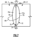
- the first and second slot portions 70/72 are in registration and together form a seal slot 80.
- the feather seal 74 is entrapped in the seal slot 80 such that the first convex arced edge 76 is adjacent the first concave back wall 70a and the second convex arced edge 78 is adjacent the second concave back wall 72a.
- the feather seal 74 provides a labyrinth seal between the adjacent seal arc segments 66-1/66-2.
- the feather seal 74 would provide a labyrinth seal between the adjacent inner platforms 62a or adjacent outer platforms 62b.
- slots can be produced by electromagnetic discharge machining (EDM) or grinding.
- EDM electromagnetic discharge machining
- the EDM process can form a rectangular slot with three closed sides, to entrap the feather seal.
- the EDM process often leaves a relatively rough surface that reduces sealing performance.
- grinding involves sweeping a grinding wheel across the side of the arc segment to cut the slot. The grinding produces a relatively smoother surface finish, but the resulting slot is open on three sides and thus requires welding the sides closed or implementing other features in order to retain the feather seal in the slot.
- the slot portions 70/72 represent a combination of the closed sides together with the smoother surface finish.
- the slot portions 70/72 are produced by grinding but without the sweeping. Instead, the grinding is conducted by moving a circular grinding wheel into the circumferential sides 66c/66d along a direction that is approximately perpendicular to the circumferential sides 66c/66d. That is, there is little or no movement of the grinding wheel back and forth along the direction between the forward and trailing sides 66a/66b. As a result, the slot portions 70/72 are cut in the shape of the grinding wheel, i.e., to a semi-circular shape.
- the concave back walls 70a/72a are arc segments that intersect the planes of the circumferential sides 66c/66d.
- the slot portions 70/72 are not cut so deep, however, that the slot portions 70/72 intersect the forward and trailing sides 66a/66b of the arc segment 66. That is, there are narrow lands 82 on the face of the sides 66c/66d between the edges of the slot portions 70/72 and the corners where the sides 66c/66d meet the forward and trailing sides 66a/66b. It is also possible that only one of the slot portions 70/72 will be ground as described above to have either the concave backs wall 70a or 70b, and that the other of the slot portions will be produced using the EDM or sweep grinding.
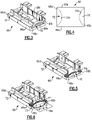
- Figure 8 illustrates an example method 90 of assembling the arc segments 66-1/66-2 with the feather seal 74.
- the arc segments 66-1/66-2 are separated.
- the arc segments 66-1/66-2 are then brought together, as represented at 92.
- the second circumferential side 66d of the second arc segment 66-2 is moved toward the first circumferential side 66c of the first seal arc segment 66-1.
- the feather seal 74 may initially be inserted into the slot portion 70 (or alternatively the slot portion 72). Once the seal arc segments 66-1/66-2 are brought into close proximity, the feather seal 74 is received into the slot portion 72.
- the feather seal 74 becomes entrapped in the slot portions 70/72.
- Figures 9 and 10 illustrate another example seal arc segment 166.
- like reference numerals designate like elements where appropriate and reference numerals with the addition of one-hundred or multiples thereof designate modified elements that are understood to incorporate the same features and benefits of the corresponding elements.
- the seal arc segment 166 includes a first slot portion 170 and a second slot portion 172 (which is similarly shaped to the first slot portion 170).
- the first slot portion 170 has the concave back wall 70a.
- the concave back wall 70a includes a notch 96.
- the notch 96 may be cast or machined.
- the first convex arced edge 76 of the feather seal 174 includes a tab 98.
- the tab 98 is received into the notch 96.
- the second convex arced edge 78 of the feather seal 174 may also include a tab 98 that is received into a notch 96 in the concave back wall 70a of the slot 172.
- the engagement of the tab or tabs 98 with the notch or notches 96 limits the feather seal 174 from moving, to maintain a proper sealing position.
- tabs 98 on both edges 76/78 may not be needed, and in some examples only one of the edges 76/78 may have a tab 98.
Landscapes
- Engineering & Computer Science (AREA)
- General Engineering & Computer Science (AREA)
- Mechanical Engineering (AREA)
- Physics & Mathematics (AREA)
- Geometry (AREA)
- Turbine Rotor Nozzle Sealing (AREA)
Description
- The present invention relates to gas turbine engines.
- A gas turbine engine typically includes a fan section, a compressor section, a combustor section and a turbine section. Air entering the compressor section is compressed and delivered into the combustion section where it is mixed with fuel and ignited to generate a high-speed exhaust gas flow. The high-speed exhaust gas flow expands through the turbine section to drive the compressor and the fan section. The compressor section typically includes low and high pressure compressors, and the turbine section includes low and high pressure turbines.
- The high pressure turbine drives the high pressure compressor through an outer shaft to form a high spool, and the low pressure turbine drives the low pressure compressor through an inner shaft to form a low spool. The fan section may also be driven by the low inner shaft. A direct drive gas turbine engine includes a fan section driven by the low spool such that the low pressure compressor, low pressure turbine and fan section rotate at a common speed in a common direction.
-
EP 2 985 419 A1 discloses a turbomachine blade assembly with feather seals seated in slots of a blade root to seal the gap between blades. - A gas turbine engine according to an aspect of the present invention includes first and second arc segments each having leading and trailing sides and first and second circumferential sides. The first circumferential side includes a first slot portion and the second circumferential side includes a second slot portion. The first and second slot portions are in registration and together define a seal slot. At least the first slot portion has a first concave arced back wall, and a feather seal entrapped in the seal slot. The feather seal has first and second feather seal circumferential sides. At least the first feather seal circumferential side has a first convex arced edge that is adjacent the first concave arced back wall of the first slot portion.
- In an embodiment, the first feather seal circumferential side is complementary in shape to the first concave arced back wall.
- In a further embodiment of any of the foregoing embodiments, the second slot portion includes a second concave arced back wall, and the second feather seal circumferential side has a second convex arced edge that is adjacent the second concave arced back wall.
- In a further embodiment of any of the foregoing embodiments, the first concave arced back wall includes a notch, and the first feather seal circumferential side includes a tab in the notch.
- In a further embodiment of any of the foregoing embodiments, the first convex arced edge and the second convex arced edge meet at first and second apexes.
- In a further embodiment of any of the foregoing embodiments, the feather seal is elongated and defines a feather seal longitudinal axis, and the feather seal is symmetric about the feather seal longitudinal axis.
- In a further embodiment of any of the foregoing embodiments, the feather seal excludes any straight edges.
- In a further embodiment of any of the foregoing embodiments, the first concave arced back wall includes a notch and the first feather seal circumferential side includes a tab that is in the notch.
- In a further embodiment of any of the foregoing embodiments, the first concave arced back wall is semi-circular.
- In a further embodiment of any of the foregoing embodiments, the first convex arced edge is semi-circular, and the first concave arced back wall and the first convex arced edge have equal radii of curvature.
- An assembly method for use in a gas turbine engine according to another aspect of the present invention includes providing first and second arc segments and a feather seal. The first and second arc segments each have leading and trailing sides and first and second circumferential sides. The first circumferential side includes a first slot portion and the second circumferential side includes a second slot portion. At least the first slot portion has a concave arced back wall. The feather seal includes first and second feather seal circumferential sides. At least the first feather seal circumferential side has a convex arced edge. The first and second arc segments are brought together to entrap the feather seal in the first and second slot portions, with the convex arced edge adjacent the concave arced back wall of the first slot portion.
- In an embodiment, the first feather seal circumferential side is complementary in shape to the first concave arced back wall.
- In a further embodiment of any of the foregoing embodiments, the second slot portion includes a second concave arced back wall, and the second feather seal circumferential side has a second convex arced edge that is adjacent the second concave arced back wall.
- In a further embodiment of any of the foregoing embodiments, the first concave arced back wall includes a notch and the first feather seal circumferential side includes a tab, and the tab is received into the notch when the first and second arc segments are brought together.
- In a further embodiment of any of the foregoing embodiments, the first concave arced back wall is semi-circular.
- The various features and advantages of the present invention will become apparent to those skilled in the art from the following detailed description. The drawings that accompany the detailed description can be briefly described as follows.
-
Figure 1 illustrates a gas turbine engine. -
Figure 2 illustrates a view of a turbine section of the gas turbine engine. -
Figure 3 illustrates an isolated view of a seal arc segment of the turbine section. -
Figure 4 illustrates a radial view of the seal arc segment. -
Figure 5 illustrates a partial cutaway view of the seal arc segment ofFigure 3 . -
Figure 6 illustrates the seal arc segment ofFigure 5 with a feather seal. -
Figure 7 illustrates two adjacent seal arc segments and a feather seal entrapped there between. -
Figure 8 illustrates a method of assembling seal arc segments and a feather seal. -
Figure 9 illustrates another example seal arc segments with a notch. -
Figure 10 illustrates the seal arc segment ofFigure 9 with a feather seal that has a tab. -
Figure 1 schematically illustrates agas turbine engine 20. Thegas turbine engine 20 is disclosed herein as a two-spool turbofan that generally incorporates afan section 22, acompressor section 24, acombustor section 26 and aturbine section 28. Thefan section 22 drives air along a bypass flow path B in a bypass duct defined within anacelle 15, and also drives air along a core flow path C for compression and communication into thecombustor section 26 then expansion through theturbine section 28. Although depicted as a two-spool turbofan gas turbine engine in the disclosed non-limiting embodiment, it should be understood that the concepts described herein are not limited to use with two-spool turbofans as the teachings may be applied to other types of turbine engines including three-spool architectures. - The
exemplary engine 20 generally includes alow speed spool 30 and ahigh speed spool 32 mounted for rotation about an engine central longitudinal axis A relative to an engine static structure 36 viaseveral bearing systems 38. It should be understood thatvarious bearing systems 38 at various locations may alternatively or additionally be provided, and the location ofbearing systems 38 may be varied as appropriate to the application. - The
low speed spool 30 generally includes aninner shaft 40 that interconnects, a first (or low)pressure compressor 44 and a first (or low)pressure turbine 46. Theinner shaft 40 is connected to thefan 42 through a speed change mechanism, which in exemplarygas turbine engine 20 is illustrated as a gearedarchitecture 48 to drive afan 42 at a lower speed than thelow speed spool 30. Thehigh speed spool 32 includes anouter shaft 50 that interconnects a second (or high)pressure compressor 52 and a second (or high)pressure turbine 54. Acombustor 56 is arranged inexemplary gas turbine 20 between thehigh pressure compressor 52 and thehigh pressure turbine 54. A mid-turbine frame 57 of the engine static structure 36 may be arranged generally between thehigh pressure turbine 54 and thelow pressure turbine 46. The mid-turbine frame 57 further supports bearingsystems 38 in theturbine section 28. Theinner shaft 40 and theouter shaft 50 are concentric and rotate viabearing systems 38 about the engine central longitudinal axis A which is collinear with their longitudinal axes. - The core airflow is compressed by the
low pressure compressor 44 then thehigh pressure compressor 52, mixed and burned with fuel in thecombustor 56, then expanded over thehigh pressure turbine 54 andlow pressure turbine 46. The mid-turbine frame 57 includesairfoils 59 which are in the core airflow path C. Theturbines low speed spool 30 andhigh speed spool 32 in response to the expansion. It will be appreciated that each of the positions of thefan section 22,compressor section 24,combustor section 26,turbine section 28, and fandrive gear system 48 may be varied. For example,gear system 48 may be located aft of the low pressure compressor, or aft of thecombustor section 26 or even aft ofturbine section 28, andfan 42 may be positioned forward or aft of the location ofgear system 48. - The
engine 20 in one example is a high-bypass geared aircraft engine. In a further example, theengine 20 bypass ratio is greater than about six, with an example embodiment being greater than about ten, the gearedarchitecture 48 is an epicyclic gear train, such as a planetary gear system or other gear system, with a gear reduction ratio of greater than about 2.3 and thelow pressure turbine 46 has a pressure ratio that is greater than about five. In one disclosed embodiment, theengine 20 bypass ratio is greater than about ten, the fan diameter is significantly larger than that of thelow pressure compressor 44, and thelow pressure turbine 46 has a pressure ratio that is greater than about five.Low pressure turbine 46 pressure ratio is pressure measured prior to inlet oflow pressure turbine 46 as related to the pressure at the outlet of thelow pressure turbine 46 prior to an exhaust nozzle. The gearedarchitecture 48 may be an epicycle gear train, such as a planetary gear system or other gear system, with a gear reduction ratio of greater than about 2.3:1 and less than about 5:1. It should be understood, however, that the above parameters are only exemplary of one embodiment of a geared architecture engine and that the present invention is applicable to other gas turbine engines including direct drive turbofans. - A significant amount of thrust is provided by the bypass flow B due to the high bypass ratio. The
fan section 22 of theengine 20 is designed for a particular flight condition -- typically cruise at about 0.8 Mach and about 35,000 feet (10,668 meters). The flight condition of 0.8 Mach and 35,000 ft (10,668 meters), with the engine at its best fuel consumption - also known as "bucket cruise Thrust Specific Fuel Consumption ('TSFC')" - is the industry standard parameter of lbm of fuel being burned divided by lbf of thrust the engine produces at that minimum point. "Low fan pressure ratio" is the pressure ratio across the fan blade alone, without a Fan Exit Guide Vane ("FEGV") system. The low fan pressure ratio as disclosed herein according to one non-limiting embodiment is less than about 1.45. "Low corrected fan tip speed" is the actual fan tip speed in ft/sec divided by an industry standard temperature correction of [(Tram °R) / (518.7 °R)]^0.5 (where °R = 9/5 x K). The "Low corrected fan tip speed" as disclosed herein according to one non-limiting embodiment is less than about 1150 ft / second (350.5 meters/second). -
Figure 2 illustrates a sectioned view through a portion of theturbine section 28 of theengine 20. Theturbine section 28 includes a row ofturbine blades 60 that are rotatable about the central engine axis A, followed by a downstream row ofstatic turbine vanes 62. For example, the turbine vanes include inner andouter platforms 62a/62b and anairfoil section 62c extending there between. Theplatforms 62a/62b are arc segments that are circumferentially arranged in an annulus around the central axis A of theengine 20. That is, theinner platforms 62a form an inner annulus and theouter platforms 62b form an outer annulus. - A blade
outer air seal 64 is located radially outwards of theblades 60. The bladeouter air seal 64 includes a plurality ofseal arc segments 66 that are circumferentially arranged in an annulus around the central axis A of theengine 20. Theseal arc segments 66 are in close radial proximity to the tips of theblades 60, to reduce the amount of gas flow that escapes around theblades 60. -
Figure 3 illustrates a representative one of theseal arc segments 66, andFigure 4 illustrates a radial outward view of theseal arc segment 66. Theseal arc segment 66 is bound by leading and trailingsides 66a/66b and first and secondcircumferential sides 66c/66d. Aninner side 66e faces into the core gaspath, toward theblades 60. Anouter side 66f faces away from the core gaspath andblades 60. The firstcircumferential side 66c includes afirst slot portion 70 and the secondcircumferential side 66d includes asecond slot portion 72. - Referring also to
Figure 5 , which shows a partial cutaway view of theseal arc segment 66, thefirst slot portion 70 extends from the firstcircumferential side 66c to a firstconcave back wall 70a. For example, the firstconcave back wall 70a is semi-circular such that thefirst slot portion 70 generally has a "D" shape. Thesecond slot portion 72 may be similarly shaped to thefirst slot portion 70. Thesecond slot portion 72 extends from the secondcircumferential side 66d to a secondconcave back wall 72a (seeFigure 4 ). For example, the secondconcave back wall 72a is also semi-circular. In a further example, the radii of curvature of theconcave back walls 70a/72a are equal. It is to be appreciated, although the examples herein are described with regard to theseal arc segments 66, it is also contemplated that the examples apply to the arc segments provided by theplatforms 62a/62b. - As shown in
Figure 6 , afeather seal 74 is received into thefirst slot portion 70, which will be described in further detail below. Thefeather seal 74 is generally a uniform-thickness flat sheet or strip that is formed of a metallic alloy, such as a nickel- or cobalt-based alloy. Thefeather seal 74 includes first and second feather sealcircumferential sides 74a/74b. In this example, the first feather sealcircumferential side 74a has a first convex arcededge 76 and the second feather sealcircumferential side 74b has a second convex arcededge 78. For instance, the arced edges 76/78 are semi-circular and have equal radii of curvatures. The arced edges 76/78 meet atapexes 77 such that thefeather seal 74 is ovular or elliptical and excludes any straight edges. Theapexes 77 may be points, but more typically will be rounded. In example shown, thefeather seal 74 is elongated and defines a feather seal longitudinal axis A1 that intersects theapexes 77, and thefeather seal 74 is symmetric about the feather seal longitudinal axis A1. As will be appreciated, asymmetric feather seal 74 would be used when theslot portions 70/72 are identical in shape. However, if theslot portions 70/72 are differently shaped, thefeather seal 74 may not be symmetrical. - As shown in
Figure 7 , when a first one of the arc segments 66-1 is arranged adjacent a second one of the seal arc segments 66-2, the first andsecond slot portions 70/72 are in registration and together form aseal slot 80. Thefeather seal 74 is entrapped in theseal slot 80 such that the first convex arcededge 76 is adjacent the firstconcave back wall 70a and the second convex arcededge 78 is adjacent the secondconcave back wall 72a. Thefeather seal 74 provides a labyrinth seal between the adjacent seal arc segments 66-1/66-2. As will be appreciated, there will be feather seals 74 between each adjacent pair of theseal arc segments 66. Alternatively, if used in thevanes 62, thefeather seal 74 would provide a labyrinth seal between the adjacentinner platforms 62a or adjacentouter platforms 62b. - The
slot portions 70/72 facilitate manufacturing of theseal arc segments 66. For instance, slots can be produced by electromagnetic discharge machining (EDM) or grinding. The EDM process can form a rectangular slot with three closed sides, to entrap the feather seal. However, the EDM process often leaves a relatively rough surface that reduces sealing performance. In comparison, grinding involves sweeping a grinding wheel across the side of the arc segment to cut the slot. The grinding produces a relatively smoother surface finish, but the resulting slot is open on three sides and thus requires welding the sides closed or implementing other features in order to retain the feather seal in the slot. - In this regard, the
slot portions 70/72 represent a combination of the closed sides together with the smoother surface finish. For instance, theslot portions 70/72 are produced by grinding but without the sweeping. Instead, the grinding is conducted by moving a circular grinding wheel into thecircumferential sides 66c/66d along a direction that is approximately perpendicular to thecircumferential sides 66c/66d. That is, there is little or no movement of the grinding wheel back and forth along the direction between the forward and trailingsides 66a/66b. As a result, theslot portions 70/72 are cut in the shape of the grinding wheel, i.e., to a semi-circular shape. For instance, theconcave back walls 70a/72a are arc segments that intersect the planes of thecircumferential sides 66c/66d. Theslot portions 70/72 are not cut so deep, however, that theslot portions 70/72 intersect the forward and trailingsides 66a/66b of thearc segment 66. That is, there arenarrow lands 82 on the face of thesides 66c/66d between the edges of theslot portions 70/72 and the corners where thesides 66c/66d meet the forward and trailingsides 66a/66b. It is also possible that only one of theslot portions 70/72 will be ground as described above to have either theconcave backs wall 70a or 70b, and that the other of the slot portions will be produced using the EDM or sweep grinding. -
Figure 8 illustrates anexample method 90 of assembling the arc segments 66-1/66-2 with thefeather seal 74. Initially, as shown at 90a, the arc segments 66-1/66-2 are separated. The arc segments 66-1/66-2 are then brought together, as represented at 92. For instance, the secondcircumferential side 66d of the second arc segment 66-2 is moved toward the firstcircumferential side 66c of the first seal arc segment 66-1. Thefeather seal 74 may initially be inserted into the slot portion 70 (or alternatively the slot portion 72). Once the seal arc segments 66-1/66-2 are brought into close proximity, thefeather seal 74 is received into theslot portion 72. As the seal arc segments 66-1/66-2 are brought into closer proximity, as shown at 90b, thefeather seal 74 becomes entrapped in theslot portions 70/72. -
Figures 9 and 10 illustrate another exampleseal arc segment 166. In this disclosure, like reference numerals designate like elements where appropriate and reference numerals with the addition of one-hundred or multiples thereof designate modified elements that are understood to incorporate the same features and benefits of the corresponding elements. In this example, theseal arc segment 166 includes afirst slot portion 170 and a second slot portion 172 (which is similarly shaped to the first slot portion 170). Thefirst slot portion 170 has theconcave back wall 70a. In this example, theconcave back wall 70a includes anotch 96. Thenotch 96 may be cast or machined. The first convex arcededge 76 of thefeather seal 174 includes atab 98. Thetab 98 is received into thenotch 96. The second convex arcededge 78 of thefeather seal 174 may also include atab 98 that is received into anotch 96 in theconcave back wall 70a of theslot 172. The engagement of the tab ortabs 98 with the notch ornotches 96 limits thefeather seal 174 from moving, to maintain a proper sealing position. As will be appreciated,tabs 98 on bothedges 76/78 may not be needed, and in some examples only one of theedges 76/78 may have atab 98. - Although a combination of features is shown in the illustrated examples, not all of them need to be combined to realize the benefits of various embodiments of this disclosure. In other words, a system designed according to an embodiment of this disclosure will not necessarily include all of the features shown in any one of the Figures or all of the portions schematically shown in the Figures. Moreover, selected features of one example embodiment may be combined with selected features of other example embodiments.
- The preceding description is exemplary rather than limiting in nature. Variations and modifications to the disclosed examples may become apparent to those skilled in the art that do not necessarily depart from this disclosure. The scope of legal protection given to this disclosure can only be determined by studying the following claims.
Claims (12)
- A gas turbine engine (20) comprising:first and second arc segments (66; 166) each having leading and trailing sides (66a, 66b) and first and second circumferential sides (66c, 66d), each first circumferential side (66c) including a first slot portion (70) and each second circumferential side (66d) including a second slot portion (72), the first slot portion (70) of the first arc segment (66; 166) and the second slot portion (72) of the second arc segment (66; 166) being in registration and together defining a seal slot (80), at least the first slot portion (70) of the first arc segment (66; 166) having a first concave arced back wall (70a); anda feather seal (74; 174) entrapped in the seal slot (80), the feather seal (74; 174) including first and second feather seal circumferential sides (74a, 74b), at least the first feather seal circumferential side (74a) having a first convex arced edge (76) that is adjacent the first concave arced back wall (70a) of the first slot portion (70).
- The gas turbine engine as recited in claim 1, wherein the first feather seal circumferential side (74a) is complementary in shape to the first concave arced back wall (70a).
- The gas turbine engine as recited in claim 1 or 2, wherein the second slot portion (72) of the second arc segment (66; 166) includes a second concave arced back wall (72a), and the second feather seal circumferential side (74b) has a second convex arced edge (78) that is adjacent the second concave arced back wall (72a).
- The gas turbine engine as recited in claim 3, wherein the first convex arced edge (76) and the second convex arced edge (78) meet at first and second apexes (77).
- The gas turbine engine as recited in any preceding claim, wherein the first concave arced back wall (70a) includes a notch (96), and the first feather seal circumferential side (74a) includes a tab (98) in the notch (96).
- The gas turbine engine as recited in any preceding claim, wherein the feather seal (74, 174) is elongated and defines a feather seal longitudinal axis (A1), and the feather seal (74, 174) is symmetric about the feather seal longitudinal axis (A1).
- The gas turbine engine as recited in any preceding claim, wherein the feather seal (74, 174) excludes any straight edges.
- The gas turbine engine as recited in any preceding claim, wherein the first concave arced back wall (70a) is semi-circular, and, optionally the first convex arced edge (76) is semi-circular, and the first concave arced back wall (70a) and the first convex arced edge (76) have equal radii of curvature.
- An assembly method (90) for use in a gas turbine engine (20), the assembly method (90) comprising:providing first and second arc segments (66; 166) and a feather seal (74; 174), the first and second arc segments (66; 166) each have leading and trailing sides (66a, 66b) and first and second circumferential sides (66c, 66d), each first circumferential side (66c) includes a first slot portion (70) and each second circumferential side (66d) includes a second slot portion (72), at least the first slot portion (70) of the first arc segment (66; 166) has a first concave arced back wall (70a), and the feather seal (74; 174) includes first and second feather seal circumferential sides (74a, 74b), at least the first feather seal circumferential side (74a) has a first convex arced edge (76); andbringing the first and second arc segments (66; 166) together to entrap the feather seal (74; 174) in the first slot portion (70) of the first arc segment (66; 166) and the second slot portion (72) of the second arc segment (66; 166) with the first convex arced edge (76) adjacent the first concave arced back wall (70a) of the first slot portion (70).
- The method as recited in claim 9, wherein the first feather seal circumferential side (74a) is complementary in shape to the first concave arced back wall (70a), and/or the first concave arced back wall (70a) is semi-circular.
- The method as recited in claim 9 or 10, wherein the second slot portion (72) of the second arc segment (66; 166) includes a second concave arced back wall (72a), and the second feather seal circumferential side (74b) has a second convex arced edge (78) that is adjacent the second concave arced back wall (72a).
- The method as recited in claim 9, 10 or 11, wherein the first concave arced back wall (70a) includes a notch (96) and the first feather seal circumferential side (74a) includes a tab (98), and the tab (96) is received into the notch (98) when the first and second arc segments (66; 166) are brought together.
Applications Claiming Priority (1)
| Application Number | Priority Date | Filing Date | Title |
|---|---|---|---|
| US16/208,876 US10890079B2 (en) | 2018-12-04 | 2018-12-04 | Gas turbine engine arc segments with arced walls |
Publications (2)
| Publication Number | Publication Date |
|---|---|
| EP3663528A1 EP3663528A1 (en) | 2020-06-10 |
| EP3663528B1 true EP3663528B1 (en) | 2022-08-10 |
Family
ID=68771590
Family Applications (1)
| Application Number | Title | Priority Date | Filing Date |
|---|---|---|---|
| EP19213670.3A Active EP3663528B1 (en) | 2018-12-04 | 2019-12-04 | Gas turbine engine arc segments with arced walls |
Country Status (2)
| Country | Link |
|---|---|
| US (1) | US10890079B2 (en) |
| EP (1) | EP3663528B1 (en) |
Families Citing this family (20)
| Publication number | Priority date | Publication date | Assignee | Title |
|---|---|---|---|---|
| FR3070718B1 (en) * | 2017-09-06 | 2019-08-23 | Safran Aircraft Engines | RING SECTOR TURBINE ASSEMBLY |
| FR3132928B1 (en) | 2022-02-21 | 2024-02-16 | Safran Ceram | ASSEMBLY FOR AN AIRCRAFT TURBOMACHINE |
| KR102821442B1 (en) | 2022-11-23 | 2025-06-16 | 두산에너빌리티 주식회사 | Turbine vane platform sealing assembly, turbine vane and gas turbine comprising it |
| KR102791366B1 (en) * | 2022-12-12 | 2025-04-07 | 두산에너빌리티 주식회사 | Turbine vane platform sealing assembly, turbine vane and gas turbine comprising it |
| US12188365B1 (en) | 2023-12-04 | 2025-01-07 | Rolls-Royce Corporation | Method and apparatus for ceramic matrix composite turbine shroud assembly |
| US12158072B1 (en) | 2023-12-04 | 2024-12-03 | Rolls-Royce Corporation | Turbine shroud segments with damping strip seals |
| US12241376B1 (en) | 2023-12-04 | 2025-03-04 | Rolls-Royce Corporation | Locating plate for use with turbine shroud assemblies |
| US12421862B2 (en) | 2023-12-04 | 2025-09-23 | Rolls-Royce Corporation | Turbine shroud assembly with angled cooling holes |
| US12286885B1 (en) | 2023-12-04 | 2025-04-29 | Rolls-Royce Corporation | Turbine assembly with confronting vane and turbine shroud segment |
| US12286906B1 (en) | 2023-12-04 | 2025-04-29 | Rolls-Royce Corporation | Locating plate for use with turbine shroud assemblies |
| US12152499B1 (en) | 2023-12-04 | 2024-11-26 | Rolls-Royce Corporation | Turbine shroud segments with strip seal assemblies having dampened ends |
| US12421870B1 (en) | 2024-04-30 | 2025-09-23 | Rolls-Royce Corporation | Pin mounted ceramic matrix composite heat shields with impingement cooling |
| US12305525B1 (en) | 2024-05-30 | 2025-05-20 | Rolls-Royce Corporation | Turbine shroud assemblies with rod seal and strip seals |
| US12258880B1 (en) | 2024-05-30 | 2025-03-25 | Rolls-Royce Corporation | Turbine shroud assemblies with inter-segment strip seal |
| US12416241B1 (en) | 2024-05-30 | 2025-09-16 | Rolls-Royce Corporation | Turbine shroud assemblies with strip seals |
| US12215593B1 (en) | 2024-05-30 | 2025-02-04 | Rolls-Royce Corporation | Turbine shroud assembly with inter-segment damping |
| US12352176B1 (en) | 2024-05-31 | 2025-07-08 | Rolls-Royce Corporation | Turbine shroud assemblies with channels for buffer cavity seal thermal management |
| US12577881B2 (en) | 2024-05-31 | 2026-03-17 | Rolls-Royce Corporation | Turbine shroud assemblies with anti-migration seals |
| US12410725B1 (en) | 2024-05-31 | 2025-09-09 | Rolls-Royce Corporation | Turbine shroud assemblies with air activated pistons for biasing buffer cavity seals |
| US12228044B1 (en) | 2024-06-26 | 2025-02-18 | Rolls-Royce Corporation | Turbine shroud system with ceramic matrix composite segments and dual inter-segment seals |
Family Cites Families (10)
| Publication number | Priority date | Publication date | Assignee | Title |
|---|---|---|---|---|
| US4767260A (en) | 1986-11-07 | 1988-08-30 | United Technologies Corporation | Stator vane platform cooling means |
| US4902198A (en) * | 1988-08-31 | 1990-02-20 | Westinghouse Electric Corp. | Apparatus for film cooling of turbine van shrouds |
| US5154577A (en) * | 1991-01-17 | 1992-10-13 | General Electric Company | Flexible three-piece seal assembly |
| US5709530A (en) | 1996-09-04 | 1998-01-20 | United Technologies Corporation | Gas turbine vane seal |
| US6431825B1 (en) * | 2000-07-28 | 2002-08-13 | Alstom (Switzerland) Ltd | Seal between static turbine parts |
| US6503051B2 (en) * | 2001-06-06 | 2003-01-07 | General Electric Company | Overlapping interference seal and methods for forming the seal |
| DE50214731D1 (en) * | 2001-08-21 | 2010-12-09 | Alstom Technology Ltd | Method for producing a groove-shaped recess and a respective groove-shaped recess |
| US20070212214A1 (en) * | 2006-03-09 | 2007-09-13 | United Technologies Corporation | Segmented component seal |
| EP2886800A1 (en) | 2013-12-18 | 2015-06-24 | Rolls-Royce Deutschland Ltd & Co KG | Guide vane assembly for a gas turbine and corresponding strip seal |
| EP2985419B1 (en) | 2014-08-13 | 2020-01-08 | United Technologies Corporation | Turbomachine blade assembly with blade root seals |
-
2018
- 2018-12-04 US US16/208,876 patent/US10890079B2/en active Active
-
2019
- 2019-12-04 EP EP19213670.3A patent/EP3663528B1/en active Active
Also Published As
| Publication number | Publication date |
|---|---|
| EP3663528A1 (en) | 2020-06-10 |
| US10890079B2 (en) | 2021-01-12 |
| US20200173295A1 (en) | 2020-06-04 |
Similar Documents
| Publication | Publication Date | Title |
|---|---|---|
| EP3663528B1 (en) | Gas turbine engine arc segments with arced walls | |
| EP3734018B1 (en) | Seal for a gas turbine engine component and corresponding method | |
| EP3543469B1 (en) | Blade outer air seal assembly with feather seal | |
| EP3093445B1 (en) | Gas turbine vane and method of forming | |
| EP3112606B1 (en) | A seal for a gas turbine engine | |
| EP3587740A1 (en) | Gas turbine engine component | |
| EP2998509B1 (en) | Endwall contouring for airfoil rows with varying airfoil geometries | |
| EP3190266A1 (en) | Rotor hub seal | |
| US11473434B2 (en) | Gas turbine engine airfoil | |
| EP3461993B1 (en) | Gas turbine engine blade | |
| EP2993303B1 (en) | Gas turbine engine component with film cooling hole with pocket | |
| EP3045666B1 (en) | Airfoil platform with cooling feed orifices | |
| EP3034805B1 (en) | Featherseal having a tapered radial portion and gas turbine engine section comprising such a feather seal | |
| EP3498978B1 (en) | Gas turbine engine vane with attachment hook | |
| EP3467260B1 (en) | Turbine blade with bowed tip | |
| EP3192969B1 (en) | Gas turbine engine component with optimized leading edge geometry | |
| EP3623587B1 (en) | Airfoil assembly for a gas turbine engine | |
| EP3470627B1 (en) | Gas turbine engine airfoil | |
| EP3477055B1 (en) | Component for a gas turbine engine comprising an airfoil | |
| US20140161616A1 (en) | Multi-piece blade for gas turbine engine | |
| EP2986823B1 (en) | Airfoil component | |
| EP3550105B1 (en) | Gas turbine engine rotor disk | |
| EP3290717A1 (en) | Compressor blade with specific spanwise pressure and velocity profile |
Legal Events
| Date | Code | Title | Description |
|---|---|---|---|
| PUAI | Public reference made under article 153(3) epc to a published international application that has entered the european phase |
Free format text: ORIGINAL CODE: 0009012 |
|
| STAA | Information on the status of an ep patent application or granted ep patent |
Free format text: STATUS: THE APPLICATION HAS BEEN PUBLISHED |
|
| AK | Designated contracting states |
Kind code of ref document: A1 Designated state(s): AL AT BE BG CH CY CZ DE DK EE ES FI FR GB GR HR HU IE IS IT LI LT LU LV MC MK MT NL NO PL PT RO RS SE SI SK SM TR |
|
| AX | Request for extension of the european patent |
Extension state: BA ME |
|
| STAA | Information on the status of an ep patent application or granted ep patent |
Free format text: STATUS: REQUEST FOR EXAMINATION WAS MADE |
|
| 17P | Request for examination filed |
Effective date: 20201210 |
|
| RBV | Designated contracting states (corrected) |
Designated state(s): AL AT BE BG CH CY CZ DE DK EE ES FI FR GB GR HR HU IE IS IT LI LT LU LV MC MK MT NL NO PL PT RO RS SE SI SK SM TR |
|
| RAP1 | Party data changed (applicant data changed or rights of an application transferred) |
Owner name: RAYTHEON TECHNOLOGIES CORPORATION |
|
| RIC1 | Information provided on ipc code assigned before grant |
Ipc: F01D 11/00 20060101ALI20211214BHEP Ipc: F01D 9/04 20060101AFI20211214BHEP |
|
| GRAP | Despatch of communication of intention to grant a patent |
Free format text: ORIGINAL CODE: EPIDOSNIGR1 |
|
| STAA | Information on the status of an ep patent application or granted ep patent |
Free format text: STATUS: GRANT OF PATENT IS INTENDED |
|
| INTG | Intention to grant announced |
Effective date: 20220216 |
|
| INTG | Intention to grant announced |
Effective date: 20220223 |
|
| GRAS | Grant fee paid |
Free format text: ORIGINAL CODE: EPIDOSNIGR3 |
|
| GRAA | (expected) grant |
Free format text: ORIGINAL CODE: 0009210 |
|
| STAA | Information on the status of an ep patent application or granted ep patent |
Free format text: STATUS: THE PATENT HAS BEEN GRANTED |
|
| AK | Designated contracting states |
Kind code of ref document: B1 Designated state(s): AL AT BE BG CH CY CZ DE DK EE ES FI FR GB GR HR HU IE IS IT LI LT LU LV MC MK MT NL NO PL PT RO RS SE SI SK SM TR |
|
| REG | Reference to a national code |
Ref country code: AT Ref legal event code: REF Ref document number: 1510687 Country of ref document: AT Kind code of ref document: T Effective date: 20220815 Ref country code: CH Ref legal event code: EP |
|
| REG | Reference to a national code |
Ref country code: IE Ref legal event code: FG4D |
|
| REG | Reference to a national code |
Ref country code: DE Ref legal event code: R096 Ref document number: 602019018060 Country of ref document: DE |
|
| REG | Reference to a national code |
Ref country code: NL Ref legal event code: MP Effective date: 20220810 |
|
| REG | Reference to a national code |
Ref country code: LT Ref legal event code: MG9D |
|
| PG25 | Lapsed in a contracting state [announced via postgrant information from national office to epo] |
Ref country code: SE Free format text: LAPSE BECAUSE OF FAILURE TO SUBMIT A TRANSLATION OF THE DESCRIPTION OR TO PAY THE FEE WITHIN THE PRESCRIBED TIME-LIMIT Effective date: 20220810 Ref country code: RS Free format text: LAPSE BECAUSE OF FAILURE TO SUBMIT A TRANSLATION OF THE DESCRIPTION OR TO PAY THE FEE WITHIN THE PRESCRIBED TIME-LIMIT Effective date: 20220810 Ref country code: PT Free format text: LAPSE BECAUSE OF FAILURE TO SUBMIT A TRANSLATION OF THE DESCRIPTION OR TO PAY THE FEE WITHIN THE PRESCRIBED TIME-LIMIT Effective date: 20221212 Ref country code: NO Free format text: LAPSE BECAUSE OF FAILURE TO SUBMIT A TRANSLATION OF THE DESCRIPTION OR TO PAY THE FEE WITHIN THE PRESCRIBED TIME-LIMIT Effective date: 20221110 Ref country code: NL Free format text: LAPSE BECAUSE OF FAILURE TO SUBMIT A TRANSLATION OF THE DESCRIPTION OR TO PAY THE FEE WITHIN THE PRESCRIBED TIME-LIMIT Effective date: 20220810 Ref country code: LV Free format text: LAPSE BECAUSE OF FAILURE TO SUBMIT A TRANSLATION OF THE DESCRIPTION OR TO PAY THE FEE WITHIN THE PRESCRIBED TIME-LIMIT Effective date: 20220810 Ref country code: LT Free format text: LAPSE BECAUSE OF FAILURE TO SUBMIT A TRANSLATION OF THE DESCRIPTION OR TO PAY THE FEE WITHIN THE PRESCRIBED TIME-LIMIT Effective date: 20220810 Ref country code: FI Free format text: LAPSE BECAUSE OF FAILURE TO SUBMIT A TRANSLATION OF THE DESCRIPTION OR TO PAY THE FEE WITHIN THE PRESCRIBED TIME-LIMIT Effective date: 20220810 |
|
| REG | Reference to a national code |
Ref country code: AT Ref legal event code: MK05 Ref document number: 1510687 Country of ref document: AT Kind code of ref document: T Effective date: 20220810 |
|
| PG25 | Lapsed in a contracting state [announced via postgrant information from national office to epo] |
Ref country code: PL Free format text: LAPSE BECAUSE OF FAILURE TO SUBMIT A TRANSLATION OF THE DESCRIPTION OR TO PAY THE FEE WITHIN THE PRESCRIBED TIME-LIMIT Effective date: 20220810 Ref country code: IS Free format text: LAPSE BECAUSE OF FAILURE TO SUBMIT A TRANSLATION OF THE DESCRIPTION OR TO PAY THE FEE WITHIN THE PRESCRIBED TIME-LIMIT Effective date: 20221210 Ref country code: HR Free format text: LAPSE BECAUSE OF FAILURE TO SUBMIT A TRANSLATION OF THE DESCRIPTION OR TO PAY THE FEE WITHIN THE PRESCRIBED TIME-LIMIT Effective date: 20220810 Ref country code: GR Free format text: LAPSE BECAUSE OF FAILURE TO SUBMIT A TRANSLATION OF THE DESCRIPTION OR TO PAY THE FEE WITHIN THE PRESCRIBED TIME-LIMIT Effective date: 20221111 |
|
| PG25 | Lapsed in a contracting state [announced via postgrant information from national office to epo] |
Ref country code: SM Free format text: LAPSE BECAUSE OF FAILURE TO SUBMIT A TRANSLATION OF THE DESCRIPTION OR TO PAY THE FEE WITHIN THE PRESCRIBED TIME-LIMIT Effective date: 20220810 Ref country code: RO Free format text: LAPSE BECAUSE OF FAILURE TO SUBMIT A TRANSLATION OF THE DESCRIPTION OR TO PAY THE FEE WITHIN THE PRESCRIBED TIME-LIMIT Effective date: 20220810 Ref country code: ES Free format text: LAPSE BECAUSE OF FAILURE TO SUBMIT A TRANSLATION OF THE DESCRIPTION OR TO PAY THE FEE WITHIN THE PRESCRIBED TIME-LIMIT Effective date: 20220810 Ref country code: DK Free format text: LAPSE BECAUSE OF FAILURE TO SUBMIT A TRANSLATION OF THE DESCRIPTION OR TO PAY THE FEE WITHIN THE PRESCRIBED TIME-LIMIT Effective date: 20220810 Ref country code: CZ Free format text: LAPSE BECAUSE OF FAILURE TO SUBMIT A TRANSLATION OF THE DESCRIPTION OR TO PAY THE FEE WITHIN THE PRESCRIBED TIME-LIMIT Effective date: 20220810 Ref country code: AT Free format text: LAPSE BECAUSE OF FAILURE TO SUBMIT A TRANSLATION OF THE DESCRIPTION OR TO PAY THE FEE WITHIN THE PRESCRIBED TIME-LIMIT Effective date: 20220810 |
|
| REG | Reference to a national code |
Ref country code: DE Ref legal event code: R097 Ref document number: 602019018060 Country of ref document: DE |
|
| PG25 | Lapsed in a contracting state [announced via postgrant information from national office to epo] |
Ref country code: SK Free format text: LAPSE BECAUSE OF FAILURE TO SUBMIT A TRANSLATION OF THE DESCRIPTION OR TO PAY THE FEE WITHIN THE PRESCRIBED TIME-LIMIT Effective date: 20220810 Ref country code: EE Free format text: LAPSE BECAUSE OF FAILURE TO SUBMIT A TRANSLATION OF THE DESCRIPTION OR TO PAY THE FEE WITHIN THE PRESCRIBED TIME-LIMIT Effective date: 20220810 |
|
| PLBE | No opposition filed within time limit |
Free format text: ORIGINAL CODE: 0009261 |
|
| STAA | Information on the status of an ep patent application or granted ep patent |
Free format text: STATUS: NO OPPOSITION FILED WITHIN TIME LIMIT |
|
| P01 | Opt-out of the competence of the unified patent court (upc) registered |
Effective date: 20230521 |
|
| PG25 | Lapsed in a contracting state [announced via postgrant information from national office to epo] |
Ref country code: AL Free format text: LAPSE BECAUSE OF FAILURE TO SUBMIT A TRANSLATION OF THE DESCRIPTION OR TO PAY THE FEE WITHIN THE PRESCRIBED TIME-LIMIT Effective date: 20220810 |
|
| 26N | No opposition filed |
Effective date: 20230511 |
|
| REG | Reference to a national code |
Ref country code: CH Ref legal event code: PL |
|
| REG | Reference to a national code |
Ref country code: BE Ref legal event code: MM Effective date: 20221231 |
|
| PG25 | Lapsed in a contracting state [announced via postgrant information from national office to epo] |
Ref country code: SI Free format text: LAPSE BECAUSE OF FAILURE TO SUBMIT A TRANSLATION OF THE DESCRIPTION OR TO PAY THE FEE WITHIN THE PRESCRIBED TIME-LIMIT Effective date: 20220810 Ref country code: LU Free format text: LAPSE BECAUSE OF NON-PAYMENT OF DUE FEES Effective date: 20221204 |
|
| PG25 | Lapsed in a contracting state [announced via postgrant information from national office to epo] |
Ref country code: LI Free format text: LAPSE BECAUSE OF NON-PAYMENT OF DUE FEES Effective date: 20221231 Ref country code: IE Free format text: LAPSE BECAUSE OF NON-PAYMENT OF DUE FEES Effective date: 20221204 Ref country code: CH Free format text: LAPSE BECAUSE OF NON-PAYMENT OF DUE FEES Effective date: 20221231 |
|
| PG25 | Lapsed in a contracting state [announced via postgrant information from national office to epo] |
Ref country code: BE Free format text: LAPSE BECAUSE OF NON-PAYMENT OF DUE FEES Effective date: 20221231 |
|
| PG25 | Lapsed in a contracting state [announced via postgrant information from national office to epo] |
Ref country code: HU Free format text: LAPSE BECAUSE OF FAILURE TO SUBMIT A TRANSLATION OF THE DESCRIPTION OR TO PAY THE FEE WITHIN THE PRESCRIBED TIME-LIMIT; INVALID AB INITIO Effective date: 20191204 |
|
| PG25 | Lapsed in a contracting state [announced via postgrant information from national office to epo] |
Ref country code: CY Free format text: LAPSE BECAUSE OF FAILURE TO SUBMIT A TRANSLATION OF THE DESCRIPTION OR TO PAY THE FEE WITHIN THE PRESCRIBED TIME-LIMIT Effective date: 20220810 |
|
| PG25 | Lapsed in a contracting state [announced via postgrant information from national office to epo] |
Ref country code: MK Free format text: LAPSE BECAUSE OF FAILURE TO SUBMIT A TRANSLATION OF THE DESCRIPTION OR TO PAY THE FEE WITHIN THE PRESCRIBED TIME-LIMIT Effective date: 20220810 Ref country code: IT Free format text: LAPSE BECAUSE OF FAILURE TO SUBMIT A TRANSLATION OF THE DESCRIPTION OR TO PAY THE FEE WITHIN THE PRESCRIBED TIME-LIMIT Effective date: 20220810 |
|
| PG25 | Lapsed in a contracting state [announced via postgrant information from national office to epo] |
Ref country code: MC Free format text: LAPSE BECAUSE OF FAILURE TO SUBMIT A TRANSLATION OF THE DESCRIPTION OR TO PAY THE FEE WITHIN THE PRESCRIBED TIME-LIMIT Effective date: 20220810 |
|
| PG25 | Lapsed in a contracting state [announced via postgrant information from national office to epo] |
Ref country code: TR Free format text: LAPSE BECAUSE OF FAILURE TO SUBMIT A TRANSLATION OF THE DESCRIPTION OR TO PAY THE FEE WITHIN THE PRESCRIBED TIME-LIMIT Effective date: 20220810 Ref country code: MC Free format text: LAPSE BECAUSE OF FAILURE TO SUBMIT A TRANSLATION OF THE DESCRIPTION OR TO PAY THE FEE WITHIN THE PRESCRIBED TIME-LIMIT Effective date: 20220810 |
|
| PG25 | Lapsed in a contracting state [announced via postgrant information from national office to epo] |
Ref country code: BG Free format text: LAPSE BECAUSE OF FAILURE TO SUBMIT A TRANSLATION OF THE DESCRIPTION OR TO PAY THE FEE WITHIN THE PRESCRIBED TIME-LIMIT Effective date: 20220810 |
|
| PG25 | Lapsed in a contracting state [announced via postgrant information from national office to epo] |
Ref country code: MT Free format text: LAPSE BECAUSE OF FAILURE TO SUBMIT A TRANSLATION OF THE DESCRIPTION OR TO PAY THE FEE WITHIN THE PRESCRIBED TIME-LIMIT Effective date: 20220810 |
|
| REG | Reference to a national code |
Ref country code: DE Ref legal event code: R081 Ref document number: 602019018060 Country of ref document: DE Owner name: RTX CORPORATION (N.D.GES.D. STAATES DELAWARE),, US Free format text: FORMER OWNER: RAYTHEON TECHNOLOGIES CORPORATION, FARMINGTON, CT, US |
|
| PGFP | Annual fee paid to national office [announced via postgrant information from national office to epo] |
Ref country code: DE Payment date: 20251126 Year of fee payment: 7 |
|
| PGFP | Annual fee paid to national office [announced via postgrant information from national office to epo] |
Ref country code: GB Payment date: 20251119 Year of fee payment: 7 |
|
| PGFP | Annual fee paid to national office [announced via postgrant information from national office to epo] |
Ref country code: FR Payment date: 20251120 Year of fee payment: 7 |