EP3050601A1 - Vorderbacken einer alpinskibindung - Google Patents
Vorderbacken einer alpinskibindung Download PDFInfo
- Publication number
- EP3050601A1 EP3050601A1 EP16151206.6A EP16151206A EP3050601A1 EP 3050601 A1 EP3050601 A1 EP 3050601A1 EP 16151206 A EP16151206 A EP 16151206A EP 3050601 A1 EP3050601 A1 EP 3050601A1
- Authority
- EP
- European Patent Office
- Prior art keywords
- jaw
- plate
- configuration
- lever
- relative
- Prior art date
- Legal status (The legal status is an assumption and is not a legal conclusion. Google has not performed a legal analysis and makes no representation as to the accuracy of the status listed.)
- Granted
Links
Images




Classifications
-
- A—HUMAN NECESSITIES
- A63—SPORTS; GAMES; AMUSEMENTS
- A63C—SKATES; SKIS; ROLLER SKATES; DESIGN OR LAYOUT OF COURTS, RINKS OR THE LIKE
- A63C9/00—Ski bindings
- A63C9/08—Ski bindings yieldable or self-releasing in the event of an accident, i.e. safety bindings
- A63C9/0807—Ski bindings yieldable or self-releasing in the event of an accident, i.e. safety bindings for both towing and downhill skiing
-
- A—HUMAN NECESSITIES
- A63—SPORTS; GAMES; AMUSEMENTS
- A63C—SKATES; SKIS; ROLLER SKATES; DESIGN OR LAYOUT OF COURTS, RINKS OR THE LIKE
- A63C9/00—Ski bindings
- A63C9/08—Ski bindings yieldable or self-releasing in the event of an accident, i.e. safety bindings
- A63C9/085—Ski bindings yieldable or self-releasing in the event of an accident, i.e. safety bindings with sole hold-downs, e.g. swingable
- A63C9/08507—Ski bindings yieldable or self-releasing in the event of an accident, i.e. safety bindings with sole hold-downs, e.g. swingable with a plurality of mobile jaws
- A63C9/08528—Ski bindings yieldable or self-releasing in the event of an accident, i.e. safety bindings with sole hold-downs, e.g. swingable with a plurality of mobile jaws pivoting about a longitudinal axis
-
- A—HUMAN NECESSITIES
- A63—SPORTS; GAMES; AMUSEMENTS
- A63C—SKATES; SKIS; ROLLER SKATES; DESIGN OR LAYOUT OF COURTS, RINKS OR THE LIKE
- A63C9/00—Ski bindings
- A63C9/08—Ski bindings yieldable or self-releasing in the event of an accident, i.e. safety bindings
- A63C9/085—Ski bindings yieldable or self-releasing in the event of an accident, i.e. safety bindings with sole hold-downs, e.g. swingable
- A63C9/08557—Details of the release mechanism
- A63C9/08564—Details of the release mechanism using cam or slide surface
-
- A—HUMAN NECESSITIES
- A63—SPORTS; GAMES; AMUSEMENTS
- A63C—SKATES; SKIS; ROLLER SKATES; DESIGN OR LAYOUT OF COURTS, RINKS OR THE LIKE
- A63C9/00—Ski bindings
- A63C9/08—Ski bindings yieldable or self-releasing in the event of an accident, i.e. safety bindings
- A63C9/085—Ski bindings yieldable or self-releasing in the event of an accident, i.e. safety bindings with sole hold-downs, e.g. swingable
- A63C9/08557—Details of the release mechanism
- A63C9/08571—Details of the release mechanism using axis and lever
-
- A—HUMAN NECESSITIES
- A63—SPORTS; GAMES; AMUSEMENTS
- A63C—SKATES; SKIS; ROLLER SKATES; DESIGN OR LAYOUT OF COURTS, RINKS OR THE LIKE
- A63C9/00—Ski bindings
- A63C9/08—Ski bindings yieldable or self-releasing in the event of an accident, i.e. safety bindings
- A63C9/085—Ski bindings yieldable or self-releasing in the event of an accident, i.e. safety bindings with sole hold-downs, e.g. swingable
- A63C9/08557—Details of the release mechanism
- A63C9/08578—Details of the release mechanism using a plurality of biasing elements
-
- A—HUMAN NECESSITIES
- A63—SPORTS; GAMES; AMUSEMENTS
- A63C—SKATES; SKIS; ROLLER SKATES; DESIGN OR LAYOUT OF COURTS, RINKS OR THE LIKE
- A63C9/00—Ski bindings
- A63C9/08—Ski bindings yieldable or self-releasing in the event of an accident, i.e. safety bindings
- A63C9/085—Ski bindings yieldable or self-releasing in the event of an accident, i.e. safety bindings with sole hold-downs, e.g. swingable
- A63C9/08557—Details of the release mechanism
- A63C9/08585—Details of the release mechanism using transverse biasing element
-
- A—HUMAN NECESSITIES
- A63—SPORTS; GAMES; AMUSEMENTS
- A63C—SKATES; SKIS; ROLLER SKATES; DESIGN OR LAYOUT OF COURTS, RINKS OR THE LIKE
- A63C9/00—Ski bindings
- A63C9/08—Ski bindings yieldable or self-releasing in the event of an accident, i.e. safety bindings
- A63C9/086—Ski bindings yieldable or self-releasing in the event of an accident, i.e. safety bindings using parts which are fixed on the shoe of the user and are releasable from the ski binding
Definitions
- the present invention relates to the technical sector of attachments for Alpine skiing, and in particular the invention concerns a toe-piece for an Alpine ski binding.
- a toe-piece for a binding for Alpine skiing of known type comprises: a plate fixable to a ski at the lower surface of the plate, two jaws, each comprising an external end, an internal end and a central body interposed between the external end and the internal end.
- the two jaws are arranged above the upper surface of the plate, so as to be facing one another.
- the two jaws are hinged to the plate by means of the relative central boy with respect to axes that are parallel to one another.
- the external end of each jaw bears a pin conformed and arranged so as to insert internally of a hole of an Alpine ski-boot.
- the toe-piece for Alpine skiing further comprises a joint constituted by a first part and a second part hinged to one another ("male" part and "female” part), and each connected to the internal end of a relative jaw.
- the joint enables the jaw to move from an open configuration into a closed configuration, and vice versa, for engaging or disengaging, with the relative pins, corresponding holes made in a ski boot.
- the toe-piece further comprises a main lever, hinged to the plate according to an axis perpendicular to the hinge axes of the jaws with the plate.
- An end of the main lever is fork-shaped, for receiving the joint in the recess of the fork.
- the toe-piece further comprises a safety lever, fork-hinged to the main lever on the opposite part with respect to the fork-shaped end.
- the safety lever is hinged with respect to an axis that is parallel to the hinge axis of the main lever with the plate.
- the toe-piece for Alpine skiing described above has however some drawbacks.
- the joint of the toe-piece of known type comprises: a large number of components cooperating for functioning of the toe-piece: this involves a very complicated assembly of the toe-piece, as well as difficult cleaning/maintenance/replacement operations of the relative components in case of necessity.
- the final user further encounters a practical disadvantage, as the plurality of components of the toe-piece determine a considerable weight thereof. This is a determining factor, in particular in the ambit of sporting competitions: in this specific sector the market demands ever-lighter toe-pieces.
- the aim of the present invention is to obviate the above-mentioned drawbacks.
- the toe-piece of the invention is advantageously structurally simpler than the known toe-pieces: for this reason there are not only shorter times and lower costs for assembly and maintenance, but also in terms of overall weight, which is modest. This responds very well indeed to market demands.
- reference numeral (1) denotes a toe-piece for Alpine skiing according to the invention.
- the toe-piece (1) of the invention in all three possible non-limiting embodiments illustrated in the figures, comprises: a plate (2) fixable to a ski; a first jaw (3) and a second jaw (4), arranged on the plate (2) in such a way as to be opposite one another and each comprising an external end (30, 40) provided with a pin (33, 43) for engaging a hole of a ski boot;
- the toe-piece (1) according to the invention has the internal end (41) of the second jaw (4) solidly constrained to the plate (2), i.e. the second jaw (4) is fixed with respect to the plate (2).
- the toe-piece (1) according to the invention has the second jaw (4) solidly constrained to the plate (2); therefore the second jaw (4) is fixed with respect to the plate (2).
- the second jaw (4) might not be in a single piece with the plate but can be rigidly fixed thereto, so that the second jaw (4) is fixed with respect to the plate (2).
- the first jaw (3) is hinged to the plate (2) at the relative internal end (31) with respect to an axis (H) that is perpendicular to the vertical plane containing the axes of the pins.
- the first jaw (3) is mobile between a first position (P1), wherein the first jaw (3) and the second jaw are in an open configuration and the relative pins (33, 43) disengage from the corresponding hole of the ski boot; and a second position (P2) wherein the first jaw (3) and the second jaw are in a closed configuration and the relative pins (33, 43) can engage the corresponding hole of the ski boot.
- the fact that the second jaw (4) is solidly fixed to the plate (2) advantageously enables a limited number of components for the toe-piece (1), which also has a particularly light weight with respect to known toe-pieces. This is also due to the fact that the toe-piece (1) is lacking the joint present in the prior art mentioned in the preamble.
- the toe-piece (1) of the invention also comprises first elastic means (5), associated to the first jaw (3), in particular the toe-piece (1) comprises an abutting element (6) constrained to the plate (2) and the first elastic means (5) are interposed between the abutting element (6) and the internal end (31) of the first jaw (3).
- the toe-piece (1) further comprises stabilising means (70, 71, 72, 9, 90, 11) configured so as to assume, when the first jaw (3) is placed in the second position (P2), i.e.
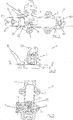
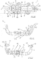
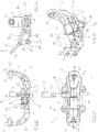
- a first configuration ( figures 1-3 , 10-12 , 23-26 ) in which they stabilise the first jaw (3) in the relative closed configuration so that the pins (33, 43) of the first jaw (3) and the second jaw (4) can removably engage the corresponding hole of the ski boot; and so as to assume a second configuration (S2) ( figures 4-6 , 13-15 , 27-30 ), in which they stabilise the first jaw (3) in the relative closed configuration so that the pins (33, 43) of the first jaw (3) and the second jaw (4) can unremovably engage the corresponding hole of the ski boot (as will become clearer in the following).
- the stabilising means (70, 71, 72) comprise: an undercut (70), fashioned at an edge of the first portion (32) of the internal end (31) of the first jaw (3); and a slide (71).
- the slide (71), comprises an abutting portion (7) which, when the slide (71) is in the relative first configuration (S1) of the stabilising means and the first jaw (3) is in the relative closed configuration (second position (P2)), is arranged at the undercut (70) of the first jaw (3), enabling oscillation thereof about the hinge axis (H) with the plate (2) (therefore without contacting the internal end (31) of the first jaw (3)) (see in particular figures 1-3 ).
- the slide (71) is mobile along a parallel direction to the hinge axis of the first jaw (3) with the plate (2) (see in particular figures 1 , 4 , 7 ).
- first configuration (S1) of the stabilising means is predisposed when the skier is about to commence a descent: in fact, since the oscillation of the first jaw (3) is enabled, as mentioned above, in opposition to the first elastic means (5), the pins (33, 43) of the first jaw (3) and the second jaw (4) are able to disengage the corresponding holes of the ski boot in a case of stress (for example if the skier falls).
- This configuration (second configuration (S2) of the stabilising means) is predisposed when the skier is about to commence an uphill tract: in fact, in this situation, the skier is constrained to the ski only with the front part of the ski boot, fixed to the toe-piece (1) so as to enable raising of the heel from the ski for carrying out the uphill climb. Therefore, the pins (33, 43) of the first jaw (3) and the second jaw (4) must in no case disengage from the corresponding holes of the ski boots.
- the stabilising means (70, 71, 72) comprise second elastic means (72), associated to the slide (71) (so as to maintain it in the relative second configuration) (visible in figures 3 , 6 , 9 ).
- the toe-piece (1) can further comprise an activating lever (8), hinged to the slide (71) according to an axis (Y) that is perpendicular to the hinge axis (H) of the first jaw (3) with the plate (2), and mobile between a raised position (see for example figures 1 and 2 ) in which the slide (71) is in the relative first configuration (S1) of the stabilising means and in a lowered position ( figures 4 ,5 ) in which the slide (71) is brought into the relative second configuration (S2) of the stabilising means, and vice versa.
- an activating lever (8) hinged to the slide (71) according to an axis (Y) that is perpendicular to the hinge axis (H) of the first jaw (3) with the plate (2), and mobile between a raised position (see for example figures 1 and 2 ) in which the slide (71) is in the relative first configuration (S1) of the stabilising means and in a lowered position ( figures 4 ,5 ) in which the slide (71) is brought into the relative second configuration (S2) of
- the skier can predispose the toe-piece (1) for an ascent or a descent.
- the activating lever (8) is in the relative raised position, but the abutting portion (7) of the slide (71) does not interfere in any way with the undercut (70) of the internal end (31) of the first jaw (3), because of the configuration of the first jaw (3) (see in particular figure 7 ).
- the first elastic means (5) keep the first jaw (3) in the relative first position.
- the abutting element (6) is solidly, i.e. rigidly constrained to the plate (2).
- the stabilising means (9, 90) comprise a blocking lever (90) flanked to the first jaw (3) and hinged to the plate (2) according to an axis (Z) parallel to the hinge axis (H) of the first jaw (3) with the plate (2).
- the blocking lever (90) comprises an appendage (901) arranged and conformed so that when the blocking lever (90) is in the relative first configuration (S1) of the stabilising means and the first jaw (3) is in the relative closed configuration (second position (P2)), the appendage (901) does not interfere with the internal end (31) of the first jaw (3), enabling oscillation of the first jaw (3) about the hinge axis (H) with the plate (2) about the hinge axis (H) with the plate (2) (see figure 11 ).
- This configuration (first configuration (S1) of the stabilising means) is predisposed when the skier is about to commence a descent, as it enables the pins (33, 34), in a case of excessive stress beyond a predetermined amount, to disengage the holes of the relative ski boot (i.e. the blocking lever (90) is moved into a position in which the relative appendage (901) does not interfere with the internal end (31) of the first jaw (3)).
- the appendage (901) interferes with the internal end (31) of the first jaw (3), blocking oscillation of the first jaw (3) about the hinge axis (H) with the plate (2) about the hinge axis (H) with the plate (2) (see the detail of figure 14 ).
- This configuration (second configuration (S2) of the stabilising means) is predisposed when the skier has to make an ascent, and the pins (33, 34) of the first jaw (3) and the second jaw (4) must not disengage the holes of the ski boots (as explained for the first embodiment described in the foregoing).
- the appendage (901) is arranged between the internal end (31) of the first jaw (3) and an abutting element (250), fixed to the plate (2), contacting both of them (see figure 14 ).
- the blocking lever (90) is further mobile in a third configuration so that when the first jaw (3) is in the relative open configuration (first position (P1)), the appendage (901) does not interfere with the internal end (31) of the first jaw (17) (and therefore the pins (33, 34 do not engage the holes of the ski boots) (see figures 16, 17 ).
- the stabilising means (9, 90) can further comprise a protuberance (9), solidly constrained to the first jaw (3); and the blocking lever (90) can comprise an edge (B) provided with at least a seating (91, 92) (see figure 17 in detail).
- a protuberance (9), solidly constrained to the first jaw (3) and the blocking lever (90) can comprise an edge (B) provided with at least a seating (91, 92) (see figure 17 in detail).
- two seatings are provided, a first seating (91) and a second seating (92).
- the blocking lever (90) when the blocking lever (90) is in the relative first configuration (first configuration (S1) of the stabilising means) and the first jaw (3) is in the relative closed configuration (second position (P2)) (descent configuration), the first seating (91) is engaged by the protuberance (9): thus the blocking lever (90) is stabilised, without however obstructing the oscillation of the first jaw (3) about the hinge axis (H) with the plate (2) (see figures 10-12 ) when stress on the plate overcomes the action of the elastic means.
- the blocking lever (90) When, on the other hand, the blocking lever (90) is in the relative second configuration (second configuration (S2) of the stabilising means) and the first jaw (3) is in the relative closed configuration (second position (P2)) (ascent configuration), the second seating (92) is engaged by the protuberance (9), stabilising the position of the blocking lever (90).
- the blocking of the first jaw (3) is optimised, as it can therefore not oscillate about the hinge axis (H) with the plate (2) (see figures 13-15 ).
- the blocking lever (90) when the blocking lever (90) is in the relative third configuration and the first jaw (3) is in the relative open position, the protuberance (9) does not engage the first seating (91) or the second seating (92), but can in any case interfere with the edge (B) for stabilising, in this case too, the blocking lever (90) (see figures 16-18 ).
- the blocking lever (90) is predisposed in the third configuration when it is necessary to "open" the toe-piece (1), i.e. disengage the pins (33, 34) from the corresponding holes of the ski boot.
- the internal end (31) of the first jaw (3) can have a semi-circular section (clearly visible in figures 12 , 15 , 18 ).
- the toe-piece (1) further comprises a connecting arm (95) which: exhibits a first end (93) coupled to the internal end (31) of the first jaw (3) and complementary thereto so as to enable movement thereof; and exhibits a second end (94) which bears the first elastic means (5).
- the abutting element (6) forms a housing (60) for receiving internally thereof the first elastic means (5) and the second end (94) of the connecting arm (95), and is hinged to the plate (2) according to an axis parallel to the hinge axis (H) of the first jaw (3) with the plate (2).
- the skier acts directly on the blocking lever (90) for predisposing the toe-piece (1) for an ascent or for a descent, or to open it.
- the toe-piece (1) of the invention is also such that the internal end (31) of the first jaw (3) has a semi-circular section (visible in figures, 21 , 25 , 29 ).
- the toe-piece (1) further comprises a connecting arm (95) which: exhibits a first end (93) coupled to the internal end (31) of the first jaw (3) and complementary thereto so as to enable movement thereof; and exhibits a second end (94) which bears the first elastic means (5).
- the abutting element (6) forms a housing (60) for receiving internally thereof the first elastic means (5) and the second end (94) of the connecting arm (95), and is hinged to the plate (2) according to an axis parallel to the hinge axis (H) of the first jaw (3) with the plate (2).
- the second position (P2) of the first jaw (3) is illustrated (closed configuration of the jaws, for engaging to the ski boot) obtained following a rotation of the first jaw (3) with respect to the plate (2) about the hinge axis (H) thereof, in an anticlockwise rotation direction seen in figures 25 and 26 with respect to figure 21 , where the abutting element (6) is rotated towards the base (clockwise direction) about the hinge axis thereof.
- the reciprocal rotation between the first jaw (3) and the abutting element (6) is made possible by the semi-circular shape of the internal end (31) of the first jaw (3), which is coupled complementarily and movably, as mentioned above, to the first end (93) of the connecting arm (95).
- the stabilising means (11) comprise a manoeuvring lever (110), hinged to the plate (2) so as to be arranged in a plane parallel to the hinge axis (H) of the first jaw (3), i.e. the manoeuvring lever (110) is hinged to the plate (2) along a hinge axis (W) that is parallel to the movement plane of the first jaw (3) and is perpendicular to the plate (2).
- the manoeuvring lever (110) is hinged to the plate (2) in such a way as to have a first end (111) facing towards inside the plate (2) and a second end (112) facing externally and frontally with respect to the plate (2) when the plate (2) is fixed to the ski.
- the stabilising means (11), in this third embodiment of the toe-piece (1), further comprise a seating (113), realised in the first end (93) of the connecting arm (95) with the manoeuvring lever (110) which is arranged and hinged to the plate (2) in such a way that the relative first end (111) is arranged and inserted internally of the seating (113).
- the stabilising means (11) further comprise an appendage (118), in a single piece with the plate (2) and projecting frontally of the plate (2) below the manoeuvring lever, and a command lever (115) which is hinged to the second end (112) of the manoeuvring lever (110) for stabilising and blocking the position of the manoeuvring lever (110) so as to obtain the second configuration (S2) of the stabilising means.
- the command lever (115) is hinged to the manoeuvring lever (110) so as to exhibit a first external arm (116) and a second internal arm (117) which at a lower end thereof bears a rolling element (119), such as for example a small wheel, predisposed to roll on the appendage (118) when the command lever (115) is rotated with respect to the manoeuvring lever (110),
- a rolling element such as for example a small wheel
- the appendage (118) has a housing (120) having a complementary shape to the rolling element (119) realised in a position such that when the rolling element (119) inserts in the housing (120), the rotation of the command lever (115) is blocked with respect to the manoeuvring lever (110) and consequently the position of the manoeuvring lever (110) is stabilised and blocked and the position of the first jaw (3) is blocked (second configuration (S2) of the stabilising means, see figure 30 ).
- the first elastic means (5) stabilise this configuration ( figure 21 ).
- the rolling element (119) is rolled along the appendage (118) distancing it from the plate (2), forcing the manoeuvring lever (110) to rotate about the hinge axis thereof (W) so that the first end (111), situated in the seating (113) of the first end (93) of the connecting arm (95), is lowered (see figure 26 ).
- the first elastic means (5) stabilise this configuration ( figures 25 and 29 ).
- the rolling element (119) is not yet inserted in the housing (120) present in the appendage (118), and the stabilising means (11) are in the first configuration (S1), i.e. they stabilise the first jaw (3) so that the pins removably engage the holes of the ski boot, for the descent position, enabling the disengaging of the ski boot if the skier should fall.
- the command lever (115) By further pulling the second arm (116) of the command lever (115) upwards ( figure 30 ), the command lever (115) is rotated with respect to the manoeuvring lever (110) so that the rolling element (119) further distances from the plate (2) up to when it inserts into the housing (120), blocking any other rotation of the command lever (115).
- the rolling element (119) is inserted in the housing (120) present in the appendage (118), and the stabilising means (11) are in the second configuration (S2), i.e. they stabilise and block the position of the first jaw (3) so that the pins unremovably engage the holes of the ski boot, for the ascent position, blocking any oscillation and/or rotation of the first jaw (3) with respect to the plate (2).
Landscapes
- Footwear And Its Accessory, Manufacturing Method And Apparatuses (AREA)
Applications Claiming Priority (1)
| Application Number | Priority Date | Filing Date | Title |
|---|---|---|---|
| ITBO20150038 | 2015-01-30 |
Publications (2)
| Publication Number | Publication Date |
|---|---|
| EP3050601A1 true EP3050601A1 (de) | 2016-08-03 |
| EP3050601B1 EP3050601B1 (de) | 2017-12-20 |
Family
ID=52774320
Family Applications (1)
| Application Number | Title | Priority Date | Filing Date |
|---|---|---|---|
| EP16151206.6A Active EP3050601B1 (de) | 2015-01-30 | 2016-01-14 | Vorderbacken einer alpinskibindung |
Country Status (1)
| Country | Link |
|---|---|
| EP (1) | EP3050601B1 (de) |
Cited By (7)
| Publication number | Priority date | Publication date | Assignee | Title |
|---|---|---|---|---|
| IT201700116389A1 (it) * | 2017-10-16 | 2019-04-16 | Stefano Maruelli | Sistema di attacco leggero con leva multifunzione di sblocco laterale |
| WO2019164457A1 (en) * | 2018-02-20 | 2019-08-29 | Gaborik Jozef | Front segment of ski binding |
| EP3854465A1 (de) * | 2020-01-24 | 2021-07-28 | The M Equipment | Vorderbacken für gleitgerät und mit einem solchen vorderbacken ausgerüstetes gleitgerät |
| FR3106501A1 (fr) * | 2020-01-24 | 2021-07-30 | The M Equipment | Butée avant pour engin de glisse, et engin de glisse équipé d’une telle butée avant |
| EP3878527A1 (de) * | 2020-03-13 | 2021-09-15 | Salewa Sport AG | Vordereinheit für eine skibindung mit definiertem öffnungsgegenanschlag an der grundplatte |
| IT202100024442A1 (it) * | 2021-09-23 | 2023-03-23 | Atk Sports S R L | Puntale di attacco da sci per sci alpinismo |
| FR3164126A1 (fr) * | 2024-07-02 | 2026-01-09 | Felisaz S.A.S. | Fixation avant pour matériel de sport d’hiver |
Citations (6)
| Publication number | Priority date | Publication date | Assignee | Title |
|---|---|---|---|---|
| EP2340876A1 (de) * | 2010-01-05 | 2011-07-06 | Salewa Sport AG | Skischuh und Bindungssystem umfassend einen Skischuh und eine Skibindung |
| EP2489415A1 (de) * | 2011-01-31 | 2012-08-22 | Marco Rigat | Vorderbacken für Tourenbindung |
| EP2674203A1 (de) * | 2012-06-12 | 2013-12-18 | Skis Rossignol | Zehenhalter mit automatischer Auslösung in Torsion |
| EP2737930A1 (de) * | 2012-11-28 | 2014-06-04 | Atk Race S.R.L. | Baugruppe für lösbare Arretierung des vorderen Teil eines Skischuhs zu einem Skiplatform für Betätigung der Telemark-Technik |
| DE102013003839A1 (de) * | 2013-03-07 | 2014-09-11 | Reinhold Zoor | Pin-Vorderbacken mit horizontalgelagerten Auslösebacken |
| EP2815794A1 (de) * | 2013-06-21 | 2014-12-24 | Atk Race S.R.L. | Zehenstück für eine alpine Skibindung |
-
2016
- 2016-01-14 EP EP16151206.6A patent/EP3050601B1/de active Active
Patent Citations (6)
| Publication number | Priority date | Publication date | Assignee | Title |
|---|---|---|---|---|
| EP2340876A1 (de) * | 2010-01-05 | 2011-07-06 | Salewa Sport AG | Skischuh und Bindungssystem umfassend einen Skischuh und eine Skibindung |
| EP2489415A1 (de) * | 2011-01-31 | 2012-08-22 | Marco Rigat | Vorderbacken für Tourenbindung |
| EP2674203A1 (de) * | 2012-06-12 | 2013-12-18 | Skis Rossignol | Zehenhalter mit automatischer Auslösung in Torsion |
| EP2737930A1 (de) * | 2012-11-28 | 2014-06-04 | Atk Race S.R.L. | Baugruppe für lösbare Arretierung des vorderen Teil eines Skischuhs zu einem Skiplatform für Betätigung der Telemark-Technik |
| DE102013003839A1 (de) * | 2013-03-07 | 2014-09-11 | Reinhold Zoor | Pin-Vorderbacken mit horizontalgelagerten Auslösebacken |
| EP2815794A1 (de) * | 2013-06-21 | 2014-12-24 | Atk Race S.R.L. | Zehenstück für eine alpine Skibindung |
Cited By (8)
| Publication number | Priority date | Publication date | Assignee | Title |
|---|---|---|---|---|
| IT201700116389A1 (it) * | 2017-10-16 | 2019-04-16 | Stefano Maruelli | Sistema di attacco leggero con leva multifunzione di sblocco laterale |
| WO2019164457A1 (en) * | 2018-02-20 | 2019-08-29 | Gaborik Jozef | Front segment of ski binding |
| EP3854465A1 (de) * | 2020-01-24 | 2021-07-28 | The M Equipment | Vorderbacken für gleitgerät und mit einem solchen vorderbacken ausgerüstetes gleitgerät |
| FR3106501A1 (fr) * | 2020-01-24 | 2021-07-30 | The M Equipment | Butée avant pour engin de glisse, et engin de glisse équipé d’une telle butée avant |
| EP3878527A1 (de) * | 2020-03-13 | 2021-09-15 | Salewa Sport AG | Vordereinheit für eine skibindung mit definiertem öffnungsgegenanschlag an der grundplatte |
| IT202100024442A1 (it) * | 2021-09-23 | 2023-03-23 | Atk Sports S R L | Puntale di attacco da sci per sci alpinismo |
| EP4154953A1 (de) * | 2021-09-23 | 2023-03-29 | Atk Sports S.R.L. | Vorderbacken einer skibindung für skitouren |
| FR3164126A1 (fr) * | 2024-07-02 | 2026-01-09 | Felisaz S.A.S. | Fixation avant pour matériel de sport d’hiver |
Also Published As
| Publication number | Publication date |
|---|---|
| EP3050601B1 (de) | 2017-12-20 |
Similar Documents
| Publication | Publication Date | Title |
|---|---|---|
| EP3050601B1 (de) | Vorderbacken einer alpinskibindung | |
| US8746729B2 (en) | Toe piece for gliding apparatus and gliding apparatus equipped with such binding | |
| EP2345463B1 (de) | Fersenhalter für eine alpine Skibindung | |
| US10010782B2 (en) | Heel-piece for binding a boot on a gliding board | |
| EP0857499B1 (de) | Skischuhbindungssystem für Snowboards | |
| EP2281614B1 (de) | Fersenteil mit zwei-armigen Vordergabel zum Einrasten mit Bolzen am Schuh | |
| EP1982608A1 (de) | Unterelement zum Einsetzen in einen Schuh mit einstellbarem Absatz | |
| NO20101289A1 (no) | Langrennsbinding, samt fremgangsmate for sammenstilling av nevnte langrennsbinding | |
| EP2547410B1 (de) | Verbessertes bindungssystem für skier mit möglichkeit zum anheben der schuhspitze | |
| EP2737930A1 (de) | Baugruppe für lösbare Arretierung des vorderen Teil eines Skischuhs zu einem Skiplatform für Betätigung der Telemark-Technik | |
| US10016672B2 (en) | Self-locking binding for telemark ski, touring ski or cross-country ski | |
| US20130307252A1 (en) | Ski binding with brake | |
| EP2946817B1 (de) | Zehenstück für skitourenbindungen | |
| US20210308552A1 (en) | Front unit for a touring binding | |
| US8739435B2 (en) | Footwear with improved sole assembly | |
| EP2682165A1 (de) | Bindung zwischen einem Ski und einem Schuh | |
| US12318679B2 (en) | Device for retaining a boot on a gliding board and gliding apparatus comprising such a device | |
| EP2345462B1 (de) | Absatzstück für eine Abfahrtsskibindung | |
| EP2135645B1 (de) | Zerlegbare Skibindung | |
| EP2815794B1 (de) | Zehenstück für eine alpine Skibindung | |
| EP2415504B1 (de) | Skibremsvorrichtung | |
| NO20101288A1 (no) | Sammenstilling for tilkobling av en støvel til en ski, samt mellomstykke for bruk i nevnte sammenstilling | |
| EP2766103B1 (de) | Skibindung | |
| US20160129336A1 (en) | Binding System For A Touring Snowboard | |
| EP3087859B1 (de) | Skischuh für skitouren |
Legal Events
| Date | Code | Title | Description |
|---|---|---|---|
| PUAI | Public reference made under article 153(3) epc to a published international application that has entered the european phase |
Free format text: ORIGINAL CODE: 0009012 |
|
| AK | Designated contracting states |
Kind code of ref document: A1 Designated state(s): AL AT BE BG CH CY CZ DE DK EE ES FI FR GB GR HR HU IE IS IT LI LT LU LV MC MK MT NL NO PL PT RO RS SE SI SK SM TR |
|
| AX | Request for extension of the european patent |
Extension state: BA ME |
|
| 17P | Request for examination filed |
Effective date: 20170126 |
|
| RBV | Designated contracting states (corrected) |
Designated state(s): AL AT BE BG CH CY CZ DE DK EE ES FI FR GB GR HR HU IE IS IT LI LT LU LV MC MK MT NL NO PL PT RO RS SE SI SK SM TR |
|
| GRAP | Despatch of communication of intention to grant a patent |
Free format text: ORIGINAL CODE: EPIDOSNIGR1 |
|
| RIC1 | Information provided on ipc code assigned before grant |
Ipc: A63C 9/085 20120101ALI20170629BHEP Ipc: A63C 9/08 20120101AFI20170629BHEP Ipc: A63C 9/086 20120101ALI20170629BHEP |
|
| INTG | Intention to grant announced |
Effective date: 20170720 |
|
| GRAS | Grant fee paid |
Free format text: ORIGINAL CODE: EPIDOSNIGR3 |
|
| GRAA | (expected) grant |
Free format text: ORIGINAL CODE: 0009210 |
|
| AK | Designated contracting states |
Kind code of ref document: B1 Designated state(s): AL AT BE BG CH CY CZ DE DK EE ES FI FR GB GR HR HU IE IS IT LI LT LU LV MC MK MT NL NO PL PT RO RS SE SI SK SM TR |
|
| REG | Reference to a national code |
Ref country code: GB Ref legal event code: FG4D |
|
| REG | Reference to a national code |
Ref country code: CH Ref legal event code: EP |
|
| REG | Reference to a national code |
Ref country code: IE Ref legal event code: FG4D |
|
| REG | Reference to a national code |
Ref country code: AT Ref legal event code: REF Ref document number: 955854 Country of ref document: AT Kind code of ref document: T Effective date: 20180115 |
|
| REG | Reference to a national code |
Ref country code: DE Ref legal event code: R096 Ref document number: 602016001101 Country of ref document: DE |
|
| REG | Reference to a national code |
Ref country code: FR Ref legal event code: PLFP Year of fee payment: 3 |
|
| REG | Reference to a national code |
Ref country code: NL Ref legal event code: MP Effective date: 20171220 |
|
| PG25 | Lapsed in a contracting state [announced via postgrant information from national office to epo] |
Ref country code: SE Free format text: LAPSE BECAUSE OF FAILURE TO SUBMIT A TRANSLATION OF THE DESCRIPTION OR TO PAY THE FEE WITHIN THE PRESCRIBED TIME-LIMIT Effective date: 20171220 Ref country code: LT Free format text: LAPSE BECAUSE OF FAILURE TO SUBMIT A TRANSLATION OF THE DESCRIPTION OR TO PAY THE FEE WITHIN THE PRESCRIBED TIME-LIMIT Effective date: 20171220 Ref country code: NO Free format text: LAPSE BECAUSE OF FAILURE TO SUBMIT A TRANSLATION OF THE DESCRIPTION OR TO PAY THE FEE WITHIN THE PRESCRIBED TIME-LIMIT Effective date: 20180320 Ref country code: FI Free format text: LAPSE BECAUSE OF FAILURE TO SUBMIT A TRANSLATION OF THE DESCRIPTION OR TO PAY THE FEE WITHIN THE PRESCRIBED TIME-LIMIT Effective date: 20171220 |
|
| REG | Reference to a national code |
Ref country code: LT Ref legal event code: MG4D |
|
| PG25 | Lapsed in a contracting state [announced via postgrant information from national office to epo] |
Ref country code: LV Free format text: LAPSE BECAUSE OF FAILURE TO SUBMIT A TRANSLATION OF THE DESCRIPTION OR TO PAY THE FEE WITHIN THE PRESCRIBED TIME-LIMIT Effective date: 20171220 Ref country code: GR Free format text: LAPSE BECAUSE OF FAILURE TO SUBMIT A TRANSLATION OF THE DESCRIPTION OR TO PAY THE FEE WITHIN THE PRESCRIBED TIME-LIMIT Effective date: 20180321 Ref country code: BG Free format text: LAPSE BECAUSE OF FAILURE TO SUBMIT A TRANSLATION OF THE DESCRIPTION OR TO PAY THE FEE WITHIN THE PRESCRIBED TIME-LIMIT Effective date: 20180320 Ref country code: RS Free format text: LAPSE BECAUSE OF FAILURE TO SUBMIT A TRANSLATION OF THE DESCRIPTION OR TO PAY THE FEE WITHIN THE PRESCRIBED TIME-LIMIT Effective date: 20171220 Ref country code: HR Free format text: LAPSE BECAUSE OF FAILURE TO SUBMIT A TRANSLATION OF THE DESCRIPTION OR TO PAY THE FEE WITHIN THE PRESCRIBED TIME-LIMIT Effective date: 20171220 |
|
| PG25 | Lapsed in a contracting state [announced via postgrant information from national office to epo] |
Ref country code: NL Free format text: LAPSE BECAUSE OF FAILURE TO SUBMIT A TRANSLATION OF THE DESCRIPTION OR TO PAY THE FEE WITHIN THE PRESCRIBED TIME-LIMIT Effective date: 20171220 |
|
| PG25 | Lapsed in a contracting state [announced via postgrant information from national office to epo] |
Ref country code: ES Free format text: LAPSE BECAUSE OF FAILURE TO SUBMIT A TRANSLATION OF THE DESCRIPTION OR TO PAY THE FEE WITHIN THE PRESCRIBED TIME-LIMIT Effective date: 20171220 Ref country code: SK Free format text: LAPSE BECAUSE OF FAILURE TO SUBMIT A TRANSLATION OF THE DESCRIPTION OR TO PAY THE FEE WITHIN THE PRESCRIBED TIME-LIMIT Effective date: 20171220 Ref country code: CY Free format text: LAPSE BECAUSE OF FAILURE TO SUBMIT A TRANSLATION OF THE DESCRIPTION OR TO PAY THE FEE WITHIN THE PRESCRIBED TIME-LIMIT Effective date: 20171220 Ref country code: CZ Free format text: LAPSE BECAUSE OF FAILURE TO SUBMIT A TRANSLATION OF THE DESCRIPTION OR TO PAY THE FEE WITHIN THE PRESCRIBED TIME-LIMIT Effective date: 20171220 Ref country code: EE Free format text: LAPSE BECAUSE OF FAILURE TO SUBMIT A TRANSLATION OF THE DESCRIPTION OR TO PAY THE FEE WITHIN THE PRESCRIBED TIME-LIMIT Effective date: 20171220 |
|
| PG25 | Lapsed in a contracting state [announced via postgrant information from national office to epo] |
Ref country code: PL Free format text: LAPSE BECAUSE OF FAILURE TO SUBMIT A TRANSLATION OF THE DESCRIPTION OR TO PAY THE FEE WITHIN THE PRESCRIBED TIME-LIMIT Effective date: 20171220 Ref country code: SM Free format text: LAPSE BECAUSE OF FAILURE TO SUBMIT A TRANSLATION OF THE DESCRIPTION OR TO PAY THE FEE WITHIN THE PRESCRIBED TIME-LIMIT Effective date: 20171220 Ref country code: RO Free format text: LAPSE BECAUSE OF FAILURE TO SUBMIT A TRANSLATION OF THE DESCRIPTION OR TO PAY THE FEE WITHIN THE PRESCRIBED TIME-LIMIT Effective date: 20171220 Ref country code: IS Free format text: LAPSE BECAUSE OF FAILURE TO SUBMIT A TRANSLATION OF THE DESCRIPTION OR TO PAY THE FEE WITHIN THE PRESCRIBED TIME-LIMIT Effective date: 20180420 |
|
| REG | Reference to a national code |
Ref country code: DE Ref legal event code: R097 Ref document number: 602016001101 Country of ref document: DE |
|
| PG25 | Lapsed in a contracting state [announced via postgrant information from national office to epo] |
Ref country code: MC Free format text: LAPSE BECAUSE OF FAILURE TO SUBMIT A TRANSLATION OF THE DESCRIPTION OR TO PAY THE FEE WITHIN THE PRESCRIBED TIME-LIMIT Effective date: 20171220 |
|
| PG25 | Lapsed in a contracting state [announced via postgrant information from national office to epo] |
Ref country code: LU Free format text: LAPSE BECAUSE OF NON-PAYMENT OF DUE FEES Effective date: 20180114 |
|
| REG | Reference to a national code |
Ref country code: IE Ref legal event code: MM4A |
|
| PLBE | No opposition filed within time limit |
Free format text: ORIGINAL CODE: 0009261 |
|
| STAA | Information on the status of an ep patent application or granted ep patent |
Free format text: STATUS: NO OPPOSITION FILED WITHIN TIME LIMIT |
|
| REG | Reference to a national code |
Ref country code: BE Ref legal event code: MM Effective date: 20180131 |
|
| PG25 | Lapsed in a contracting state [announced via postgrant information from national office to epo] |
Ref country code: DK Free format text: LAPSE BECAUSE OF FAILURE TO SUBMIT A TRANSLATION OF THE DESCRIPTION OR TO PAY THE FEE WITHIN THE PRESCRIBED TIME-LIMIT Effective date: 20171220 Ref country code: BE Free format text: LAPSE BECAUSE OF NON-PAYMENT OF DUE FEES Effective date: 20180131 |
|
| 26N | No opposition filed |
Effective date: 20180921 |
|
| PG25 | Lapsed in a contracting state [announced via postgrant information from national office to epo] |
Ref country code: IE Free format text: LAPSE BECAUSE OF NON-PAYMENT OF DUE FEES Effective date: 20180114 |
|
| PG25 | Lapsed in a contracting state [announced via postgrant information from national office to epo] |
Ref country code: SI Free format text: LAPSE BECAUSE OF FAILURE TO SUBMIT A TRANSLATION OF THE DESCRIPTION OR TO PAY THE FEE WITHIN THE PRESCRIBED TIME-LIMIT Effective date: 20171220 |
|
| PG25 | Lapsed in a contracting state [announced via postgrant information from national office to epo] |
Ref country code: MT Free format text: LAPSE BECAUSE OF NON-PAYMENT OF DUE FEES Effective date: 20180114 |
|
| PG25 | Lapsed in a contracting state [announced via postgrant information from national office to epo] |
Ref country code: TR Free format text: LAPSE BECAUSE OF FAILURE TO SUBMIT A TRANSLATION OF THE DESCRIPTION OR TO PAY THE FEE WITHIN THE PRESCRIBED TIME-LIMIT Effective date: 20171220 |
|
| PG25 | Lapsed in a contracting state [announced via postgrant information from national office to epo] |
Ref country code: PT Free format text: LAPSE BECAUSE OF FAILURE TO SUBMIT A TRANSLATION OF THE DESCRIPTION OR TO PAY THE FEE WITHIN THE PRESCRIBED TIME-LIMIT Effective date: 20171220 |
|
| PGFP | Annual fee paid to national office [announced via postgrant information from national office to epo] |
Ref country code: CH Payment date: 20200129 Year of fee payment: 5 |
|
| PG25 | Lapsed in a contracting state [announced via postgrant information from national office to epo] |
Ref country code: HU Free format text: LAPSE BECAUSE OF FAILURE TO SUBMIT A TRANSLATION OF THE DESCRIPTION OR TO PAY THE FEE WITHIN THE PRESCRIBED TIME-LIMIT; INVALID AB INITIO Effective date: 20160114 Ref country code: MK Free format text: LAPSE BECAUSE OF NON-PAYMENT OF DUE FEES Effective date: 20171220 |
|
| PG25 | Lapsed in a contracting state [announced via postgrant information from national office to epo] |
Ref country code: AL Free format text: LAPSE BECAUSE OF FAILURE TO SUBMIT A TRANSLATION OF THE DESCRIPTION OR TO PAY THE FEE WITHIN THE PRESCRIBED TIME-LIMIT Effective date: 20171220 |
|
| GBPC | Gb: european patent ceased through non-payment of renewal fee |
Effective date: 20200114 |
|
| PG25 | Lapsed in a contracting state [announced via postgrant information from national office to epo] |
Ref country code: GB Free format text: LAPSE BECAUSE OF NON-PAYMENT OF DUE FEES Effective date: 20200114 |
|
| REG | Reference to a national code |
Ref country code: AT Ref legal event code: UEP Ref document number: 955854 Country of ref document: AT Kind code of ref document: T Effective date: 20171220 |
|
| REG | Reference to a national code |
Ref country code: CH Ref legal event code: PL |
|
| PG25 | Lapsed in a contracting state [announced via postgrant information from national office to epo] |
Ref country code: LI Free format text: LAPSE BECAUSE OF NON-PAYMENT OF DUE FEES Effective date: 20210131 Ref country code: CH Free format text: LAPSE BECAUSE OF NON-PAYMENT OF DUE FEES Effective date: 20210131 |
|
| REG | Reference to a national code |
Ref country code: AT Ref legal event code: MM01 Ref document number: 955854 Country of ref document: AT Kind code of ref document: T Effective date: 20210114 |
|
| PG25 | Lapsed in a contracting state [announced via postgrant information from national office to epo] |
Ref country code: AT Free format text: LAPSE BECAUSE OF NON-PAYMENT OF DUE FEES Effective date: 20210114 |
|
| P01 | Opt-out of the competence of the unified patent court (upc) registered |
Effective date: 20230523 |
|
| PGFP | Annual fee paid to national office [announced via postgrant information from national office to epo] |
Ref country code: DE Payment date: 20260223 Year of fee payment: 11 |
|
| PGFP | Annual fee paid to national office [announced via postgrant information from national office to epo] |
Ref country code: IT Payment date: 20260130 Year of fee payment: 11 |
|
| PGFP | Annual fee paid to national office [announced via postgrant information from national office to epo] |
Ref country code: FR Payment date: 20260122 Year of fee payment: 11 |