EP3050425A1 - Antriebsverbindung für eine häckseltrommel und erntemaschine - Google Patents
Antriebsverbindung für eine häckseltrommel und erntemaschine Download PDFInfo
- Publication number
- EP3050425A1 EP3050425A1 EP16153433.4A EP16153433A EP3050425A1 EP 3050425 A1 EP3050425 A1 EP 3050425A1 EP 16153433 A EP16153433 A EP 16153433A EP 3050425 A1 EP3050425 A1 EP 3050425A1
- Authority
- EP
- European Patent Office
- Prior art keywords
- drive
- external thread
- pressure plate
- threaded bore
- drive connection
- Prior art date
- Legal status (The legal status is an assumption and is not a legal conclusion. Google has not performed a legal analysis and makes no representation as to the accuracy of the status listed.)
- Granted
Links
Images
Classifications
-
- F—MECHANICAL ENGINEERING; LIGHTING; HEATING; WEAPONS; BLASTING
- F16—ENGINEERING ELEMENTS AND UNITS; GENERAL MEASURES FOR PRODUCING AND MAINTAINING EFFECTIVE FUNCTIONING OF MACHINES OR INSTALLATIONS; THERMAL INSULATION IN GENERAL
- F16D—COUPLINGS FOR TRANSMITTING ROTATION; CLUTCHES; BRAKES
- F16D1/00—Couplings for rigidly connecting two coaxial shafts or other movable machine elements
- F16D1/06—Couplings for rigidly connecting two coaxial shafts or other movable machine elements for attachment of a member on a shaft or on a shaft-end
-
- A—HUMAN NECESSITIES
- A01—AGRICULTURE; FORESTRY; ANIMAL HUSBANDRY; HUNTING; TRAPPING; FISHING
- A01F—PROCESSING OF HARVESTED PRODUCE; HAY OR STRAW PRESSES; DEVICES FOR STORING AGRICULTURAL OR HORTICULTURAL PRODUCE
- A01F29/00—Cutting apparatus specially adapted for cutting hay, straw or the like
- A01F29/09—Details
- A01F29/14—Drives
-
- A—HUMAN NECESSITIES
- A01—AGRICULTURE; FORESTRY; ANIMAL HUSBANDRY; HUNTING; TRAPPING; FISHING
- A01D—HARVESTING; MOWING
- A01D69/00—Driving mechanisms or parts thereof for harvesters or mowers
- A01D69/08—Clutches
-
- F—MECHANICAL ENGINEERING; LIGHTING; HEATING; WEAPONS; BLASTING
- F16—ENGINEERING ELEMENTS AND UNITS; GENERAL MEASURES FOR PRODUCING AND MAINTAINING EFFECTIVE FUNCTIONING OF MACHINES OR INSTALLATIONS; THERMAL INSULATION IN GENERAL
- F16D—COUPLINGS FOR TRANSMITTING ROTATION; CLUTCHES; BRAKES
- F16D13/00—Friction clutches
- F16D13/22—Friction clutches with axially-movable clutching members
- F16D13/38—Friction clutches with axially-movable clutching members with flat clutching surfaces, e.g. discs
- F16D13/52—Clutches with multiple lamellae ; Clutches in which three or more axially moveable members are fixed alternately to the shafts to be coupled and are pressed from one side towards an axially-located member
-
- A—HUMAN NECESSITIES
- A01—AGRICULTURE; FORESTRY; ANIMAL HUSBANDRY; HUNTING; TRAPPING; FISHING
- A01D—HARVESTING; MOWING
- A01D2101/00—Lawn-mowers
Definitions
- the invention relates to a drive connection for a chopper drum and a harvester with a chopper with such a drive connection.
- the chopper means may be formed as one or two chopper drum means, the former comprising a rotating drum fitted with knives which rotates against a fixed knife, the blades of the knives being axially aligned with an axis of rotation of the drum and that chaffing crop is guided between the chopper drum and the fixed knife and thereby crushed.
- the second comprises two mutually rotating cutterheads equipped with knives, wherein the crop to be chopped is guided between the two chopper drums and thereby crushed.
- the blades of the blades are each aligned axially with the axes of rotation of the drums.
- the speed and also the number of knives arranged on a chopper drum can vary.
- a fine adjustment of the drums must be done to each other to ensure a precise, accurately spaced backlash of the knife.
- this is often possible only after assembly of the harvester and in particular after installation of the chopper.
- one of the chopping drums is usually after their installation or arranged after the assembly is not adjustable in the drive train, wherein the second chopper drum from the drive train releasably and their position or rotation position relative to the other chopper drum is designed to be adjustable.
- this is done via a detachable flange, screw or bolt connection between a drive wheel in the drive train of the chaff device and the chopper drum to be adjusted.
- the adjustment to be made or the so-called "timing" takes place in an open gearbox or open housing of the drive train of the chopper, which involves a certain assembly effort and loss of time.
- a drive connection for a Hußseltrommel with a drive wheel, a drive shaft and a clutch assembly
- the clutch assembly comprises a clutch disk package with drive wheel side clutch plates and drive shaft side clutch discs arranged by a arranged on a shaft end of the drive shaft and acting on the clutch disc package pressure plate and a concentric Arranged to the drive shaft connecting bolt with an axial force and can be brought into frictional engagement
- the connecting bolt has a first external thread having a formed in the pressure plate first threaded bore, and a second external thread, which is engageable with a second threaded bore formed in the shaft end wherein the first and second external threads and the first and second threaded bores have mutually oppositely formed thread seals.
- the connecting bolt has in the region of the first external thread on a maximum diameter, so that the first external thread can be formed as extending to an open end of the connecting bolt thread and especially at the open end of the connecting pin no flange, wreath or a different kind radially outward directed paragraph is formed.
- acting on the connecting bolt bending moments are avoided, which would be introduced at the formation of a flange, ring or other like radially outwardly directed paragraph due to a resulting contact surface or contact surface to the pressure plate on the connecting bolt, which in turn could lead to breakage of the connecting bolt.
- the pressure plate is designed such that the shaft end is covered. Furthermore, one of the clutch assembly facing annular surface is formed on the pressure plate.
- the Pressure plate is preferably brought with its annular surface with the clutch assembly in contact and clamped on this, whereby an axial tension is performed on the clutch disc package and this can be brought into frictional engagement. In the reverse manner, the pressure plate can be moved away with its annular surface of the clutch assembly and the frictional engagement can be solved accordingly.
- the coupling arrangement comprises a clutch ring, which is axially displaceably mounted on the shaft end region between the pressure plate and the clutch pack and has an annular surface aligned with the shaft end, which can be brought into engagement with the annular surface of the pressure plate facing the clutch arrangement.
- the first external thread and the first threaded bore have a thread pitch that is different from the second external thread or the second threaded bore and a thread diameter that is different from the second external thread or the second threaded bore.
- the different thread pitch allows to influence the extent to which the pressure plate and the drive shaft are moved toward each other or can be moved away from each other.
- the different thread diameters allow a functional and maintenance-friendly assembly.
- the first external thread and the first threaded bore with respect to the second external thread or the second threaded hole larger thread pitch provided.
- the first external thread and the first threaded bore have a thread diameter which is larger for the second external thread or for the second threaded bore.
- the ratio of thread and thread diameter shown here in the embodiment is matched to the embodiment described later and has been found in this context as a possible arrangement. Other, deviating arrangements are therefore also possible.
- a spacer sleeve On the shaft shoulder of the drive shaft, a spacer sleeve is mounted on which axially support the clutch disk pack and the drive wheel, wherein the clutch disk pack between the spacer sleeve and the pressure plate is arranged.
- the spacer sleeve thus provides a means for generating a necessary force when applying the axial force on the part of the connecting bolt and at the same time also provides a shoulder on which the drive wheel comes axially to the plant and thus axially fixed with play.
- a threaded pin is arranged, which can be brought into engagement with a through hole formed in the pressure plate and with a threaded bore formed in the shaft end in order to provide an anti-rotation of the pressure plate relative to the drive shaft.
- the grub screw is guided through the through hole and screwed into the threaded hole.
- a connecting plate and a locking pin is provided, for example, a spring connector, wherein the connecting plate connects the tool attachment of the connecting bolt with the threaded bolt, so that a rotation of the connecting bolt is blocked relative to the threaded pin and wherein the locking pin extends transversely to the threaded pin through this and the connecting plate axially secured against the threaded pin.
- the locking pin preferably extends through a transverse bore in the threaded pin and fixes the connecting plate against axial displacement. This ensures that the connection plate can not be released axially from the threaded pin or from the connecting bolt, so that the created anti-rotation protection persists permanently even under operating conditions.
- a drive connection for a chopper is particularly suitable for use in a harvester, such as a forage harvester or a sugarcane harvester, the latter is usually equipped with a chopper with two chopper drums and one of the drums for adjusting the chopping rate and the Heckerselêtes with respect to the other drum detached from the drive train and can be adjusted.
- Forage harvesters are usually provided with a chopping device with only one rotating chopper drum, which, however, may also have a drive connection according to the above embodiment.
- other harvesters in which a chopper is provided may be equipped with such a drive connection and are hereby taken into account.
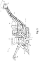
- FIG. 1 shows a harvester 10 in the form of a sugarcane harvester for harvesting rows of sugarcane.
- the harvester 10 includes a frame 12 with right (not shown) and left chain drives 14.
- An internal combustion engine 16 drives the chain drives and supplies other drive and power units arranged and driven on the harvester 10.
- a vehicle cabin 18 is arranged at the front part of the frame 12.
- the harvesting machine 10 comprises an upper cutter 20, with which the sugar cane is trimmed at the top during the harvesting process, in order to reduce a proportion of leaves on the crop in advance.
- a bottom cutting unit 24 is further provided, which serves to separate the sugar cane above the ground.
- hold-down rollers 26 are arranged, which press down the stalky sugar cane before being separated by the bottom cutting unit 24 in the forward direction.
- the bottom cutting unit 24 is adjoined by a plurality of rearward and upward juxtaposed pairs of feed rollers 28, 30 which convey the cut cane into a chopper 36 formed with chopper drums 32, 34, the chopper 36 comprising upper and lower chopper drums 32, 34.
- the chopper 36 crushes the stalky sugar cane, which is then fed into a cleaning chamber 38 with separator 40.
- the shredded material of mitermernteten leaves and other impurities by a provided in the separator 40 fan (not shown) is cleaned. From there, the shredded material falls on a conveyor belt 42 and is passed into a second separator 44 for further cleaning before it is unloaded from the rear end of the conveyor belt 44 in a following the harvesting machine 10 loader wagons (not shown).
- the chopping drums 32 and 34 arranged in the chopper 36 are driven by a common drive means (not shown).
- the chopping drums 32, 34 themselves are not shown here in detail and fitted in a conventional manner with known from the prior art chopping knives whose cutting edges are aligned axially to the axes of rotation of the chopping drums 32, 34.
- One of the chopping drums 32, 34 is with a drive connection 46 as shown in the FIGS. 2 to 4 equipped.
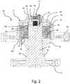
- the drive connection 46 includes a drive wheel 48, a drive shaft 50 and a clutch assembly 52, wherein the clutch assembly 52 includes a clutch pack 54 with drive gear and drive shaft side clutch plates 56, 58, and one on a shaft end 60 of the drive shaft 50 axially slidably mounted coupling ring 62.
- the coupling ring 62 is axially displaceably mounted on the drive shaft 50 between a pressure plate 64 and the clutch disk package 54 and has an annular surface 66 oriented toward the shaft end region 60, which can be brought into engagement with an annular surface 68 of the pressure plate 64 facing the clutch arrangement 52.
- the coupling ring 62 has an annular surface 70 aligned with the clutch disc package 54, with which the coupling ring 62 can be brought into axial displacement with the clutch disc package 54.
- the drive shaft 50 is followed by a fastening flange 71 for connection to the chopper drum 32, 34.
- a connecting bolt 72 arranged concentrically with the drive shaft connects the pressure plate 64 to the drive shaft 50.
- the connecting bolt 72 has a first external thread 74 and a second external thread 76.
- the first external thread 74 engages with a first threaded bore 78 formed in the pressure plate 64 and the second external thread 76 with a second threaded bore 80 formed in the shaft end region 60, the first and second external threads 74, 76 and the first and second threaded bores 78, 80 have mutually oppositely formed thread seals.
- About the connecting pin 72 is between the drive shaft 50 and the pressure plate 64 a Axialkraft introduced in turn is transmitted from the pressure plate 64 to the coupling ring 62 and thus acts on the clutch disk package 54 and this brings into frictional engagement.
- the above-described design of the clutch assembly 52 between the drive shaft 50 and the drive wheel 48 allows the clutch assembly 52 to be loosened or axially tensioned from outside a housing of the drive connection 46 or the chopper 36 in order to loosen the intended clutch disk package 54 or in frictional engagement bring to.
- By opposing external threads 74, 76 on only one connecting pin 72 the pressure plate 64 and the drive shaft 50 are moved away from each other or toward each other and thus, depending on the direction of rotation, the clutch disc package 54 solved or brought into frictional engagement with a rotational movement of the connecting pin 72.
- This is an extremely simple and practical solution for producing the frictional connection between the drive wheel 48 and drive shaft 50 of the cutterhead 32, 34 is created with minimal maintenance and minimal variety of parts.
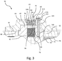
- the connecting bolt 72 has a maximum diameter in the region of the first external thread 74, so that the first external thread 74 is formed as a thread, which extends from an end 82 of the connecting bolt 72 located at the end of the shaft 60 to an open end 83 in the direction of the center of the connecting bolt 72 runs (see Figures 3 and 4 ).
- a tool attachment 84 is formed, via which the connecting bolt 72 is rotatable with a corresponding tool.
- the tool attachment 84 is here in FIG Formed an external hex. Other embodiments, such as a hexagon socket or the like, are also conceivable.
- the first external thread 74 is engaged with a corresponding first threaded bore 78 formed in the pressure plate 64.
- the first external thread 74 is followed by a shaft shoulder 88 starting from an end 86 of the first external thread 74 situated inside the first threaded hole 78.
- the shaft shoulder 88 is followed by the second external thread 76, which extends into the interior of the shaft end region 60 or into the second threaded bore 80.
- the connecting bolt 72 has a smaller diameter in the region of the second external thread 78 than in the region of the first external thread 74. Accordingly, the first and second threaded bores 78, 80 are provided with different diameters.
- the first external thread 74 and the first threaded bore 78 have a different thread pitch from the second external thread 76 or the second threaded bore 80, with the second external thread 76 and the second threaded bore 80 here have smaller thread pitch.
- the (different) thread pitches can be used to influence the extent to which the pressure plate 64 and the drive shaft 50 are moved away from each other when a rotational movement of the connecting pin 72 is initiated.
- the various thread diameters allow a functional and maintenance-friendly assembly of the clutch assembly 52.
- the in the FIGS. 2 to 4 shown ratios of thread pitches and thread diameter are tailored to the application and have in this Context as a possible arrangement. Other, deviating conditions are therefore also possible.
- a shaft shoulder 90 is formed on the drive shaft 50 ( FIG. 2 ), wherein on the shaft end portion 60 of the drive shaft 50, a spacer sleeve 92 is mounted, which comes at a first end 94 at the shaft shoulder 90 axially to the plant.
- a the first end 94 opposite end 96 of the spacer sleeve 92 serves as an abutment for a coupling ring 62 opposite end 98 of the clutch disk package 54 and formed on the drive wheel 48 annular surface 100, so that the clutch disk package 54 and the drive wheel 48 axially to the Support spacer sleeve 92, wherein the clutch disk package 54 is disposed between the spacer sleeve 92 and the pressure plate 64.
- the spacer sleeve 92 thus provides a means for generating a force necessary to apply the axial force on the part of the connecting bolt 72 supporting force or opposing force and at the same time also provides a shoulder on which the drive wheel comes axially to the plant and thus axially fixed play on the drive shaft 50.
- a threaded pin 102 is arranged, which can be brought into engagement with a through hole 104 formed in the pressure plate 64 and with a threaded bore 106 formed in the shaft end region 60.
- the threaded pin 102 is guided through the through hole 104 and screwed into the threaded hole 106. This avoids that with the pressure plate 64 and the drive shaft 50th engaged connecting pin 72 by rotating the pressure plate 64 relative to the drive shaft 50 with twisted.
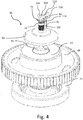
- a connecting plate 108 and a locking pin 110 is provided, for example a spring connector, wherein the connecting plate 108 has a round hole 112 and a hexagonal hole 114 and thereby connects the hexagonal tool attachment 84 of the connecting pin 72 with the round threaded pin 102, so that a rotation of the connecting pin 72nd is blocked relative to the threaded pin 102.
- the securing pin 110 extends transversely to the threaded pin 102 through a transverse bore 116 on the threaded pin 102 and fixes or secures the connecting plate 108 on the threaded pin 102.
- a drive connection 46 for a chopper 36 is particularly suitable for use in a harvester 10, such as a forage harvester or sugarcane harvester, the latter is usually equipped with a chopper 36 with two chopper drums 32, 34 and one of the drums 32, 34 for Adjusting the rate of chopping and the Heckerselnieses relative to the other drum 32, 34 can be solved by the drive train 46 positioned.vom powertrain and adjusted accordingly.
- Forage harvesters are usually provided with a chopping device 36 with only one rotating chopper drum 32, 34, which, however, may also have a drive connection 46 according to the above embodiment.
- Other harvesting machines in which a chopping device 36 is provided may be equipped with such a drive connection 46 and are hereby taken into consideration.
Landscapes
- Engineering & Computer Science (AREA)
- General Engineering & Computer Science (AREA)
- Life Sciences & Earth Sciences (AREA)
- Environmental Sciences (AREA)
- Mechanical Engineering (AREA)
- Mechanical Operated Clutches (AREA)
- One-Way And Automatic Clutches, And Combinations Of Different Clutches (AREA)
- Harvester Elements (AREA)
Abstract
Description
- Die Erfindung betrifft eine Antriebsverbindung für eine Häckseltrommel sowie eine Erntemaschine mit einer Häckseleinrichtung mit einer solchen Antriebsverbindung.
- Es ist bekannt, Erntemaschinen mit einer Häckseleinrichtung auszustatten, in der das Erntegut, vorzugsweise stängeliges Erntegut wie Mais oder Zuckerrohr, während des Ernteprozesses nach dem Schneiden oder Abtrennen vom Boden in einem weiteren Arbeitsschritt zerhäckselt bzw. zerkleinert wird. Derartige Häckseleinrichtungen werden beispielsweise in Feldhäckslern oder auch in Zuckerrohrerntemaschinen eingesetzt. Die Häckseleinrichtungen können als ein- oder zwei-Häckseltrommel-Einrichtungen ausgebildet sein, wobei Erstere eine sich drehende und mit Messern bestückte Trommel umfasst, die gegen ein feststehendes Messer dreht, wobei die Schneiden der Messer axial zu einer Rotationsachse der Trommel ausgerichtet sind und das zu häckselnde Erntegut zwischen die Häckseltrommel und das feststehende Messer geführt und dabei zerkleinert wird. Zweitere dagegen umfasst zwei gegeneinander drehende mit Messern bestückte Häckseltrommeln, wobei das zu häckselnde Erntegut zwischen die beiden Häckseltrommeln geführt und dabei zerkleinert wird. Auch hier sind die Schneiden der Messer jeweils axial zu den Rotationsachsen der Trommeln ausgerichtet. Je nach gewünschtem Häckselgrad kann die Drehzahl und auch die Anzahl der auf einer Häckseltrommel angeordneten Messer variieren. Insbesondere bei einer zwei-Häckseltrommel-Einrichtung muss eine Feinjustierung der Trommeln zueinander erfolgen, um ein präzises, abstandsgenaues Gegeneinanderlaufen der Messer zu gewährleisten. Dies ist jedoch oft erst nach der Montage der Erntemaschine und insbesondere nach Einbau der Häckseleinrichtung möglich. Bei letzterer ist eine der Häckseltrommeln meist nach ihrem Einbau bzw. nach der Montage nicht justierbar im Antriebsstrang angeordnet, wobei die zweite Häckseltrommel vom Antriebsstrang lösbar und ihre Position bzw. Umdrehungsstellung gegenüber der anderen Häckseltrommel entsprechend einstellbar ausgebildet ist. In der Regel erfolgt dies über eine lösbare Flansch-, Schraub- oder Bolzenverbindung zwischen einem Antriebsrad im Antriebsstrang der Häcksel-Einrichtung und der einzustellenden Häckseltrommel. Die vorzunehmende Einstellung bzw. das sogenannte "Timing" erfolgt dabei bei einem geöffneten Getriebe bzw. geöffnetem Gehäuse des Antriebsstrangs der Häckseleinrichtung, was einen gewissen Montageaufwand und Zeitverlust mit sich bringt. Es ist ferner bekannt, ein Öffnen des Getriebes bzw. des Gehäuse des Antriebsstrangs zu vermeiden, indem eine Kupplungsanordnung an einer der Häckseltrommeln vorgesehen ist, um einen Kraftschluss bzw. ein Lösen der Kupplungseinrichtung von außerhalb des Getriebes bzw. des Gehäuses des Antriebsstrangs zu ermöglichen. Nachteilig hier ist, dass bekannte Lösungen den erforderlichen Kraftschluss für die Kupplungsanordnung durch mehrere Verbindungsbolzen bzw. Schrauben vorsehen, die in einem gewissen Radius zur Rotationsachse der Häckseltrommel angeordnet sind und dadurch unter hohen Wechselbiegespannungen stehen. Zudem sind die Schrauben mit Schraubenköpfen versehen, deren Absätze zum Schraubenschaft zusätzlich Angriffspunkte für Wechselspannungen durch Biegemomente bieten. Dies kann oftmals zum Bruch der Schraube führen und damit den Ausfall der Häckseleinrichtung mit sich bringen.
- Ein Bestreben liegt daher darin, eine Antriebsverbindung zu schaffen, die ein einfaches und praktikables Einstellen oder Justieren bzw. "Timing" der Häckseleinrichtung ermöglicht und mit der die oben genannten Probleme überwunden werden.
- Eine derartige Antriebsverbindung wird durch die Lehre der Patentansprüche 1 und 11 vorgeschlagen. Weitere vorteilhafte Ausgestaltungen und Weiterbildungen gehen aus den Unteransprüchen hervor.
- Es wird eine Antriebsverbindung für eine Häckseltrommel vorgeschlagen, mit einem Antriebsrad, einer Antriebswelle und einer Kupplungsanordnung, wobei die Kupplungsanordnung ein Kupplungsscheibenpaket mit antriebsradseitigen Kupplungsscheiben und antriebswellenseitigen Kupplungsscheiben umfasst, das von einer auf einem Wellenendbereich der Antriebswelle angeordneten und auf das Kupplungsscheibenpaket wirkenden Druckplatte und einem konzentrisch zur Antriebswelle angeordneten Verbindungsbolzen mit einer Axialkraft beaufschlagbar und in Reibschluss bringbar ist, wobei der Verbindungsbolzen ein erstes Außengewinde aufweist, welches mit einer in der Druckplatte ausgebildeten ersten Gewindebohrung, und ein zweites Außengewinde aufweist, welches mit einer im Wellenende ausgebildeten zweiten Gewindebohrung in Eingriff bringbar ist, wobei das erste und zweite Außengewinde sowie die erste und zweite Gewindebohrung zueinander entgegengesetzt ausgebildete Gewinderichtungen aufweisen. Durch die oben genannte Ausbildung der Kupplungsanordnung zwischen Antriebswelle und Antriebsrad wird ermöglicht, die Kupplungsanordnung von außerhalb des Gehäuses des Antriebsstrangs bzw. der Häckseleinrichtung zu lösen bzw. axial zu spannen, um das vorgesehene Kupplungsscheibenpaket zu lockern bzw. in Reibschluss zu bringen. Durch die entgegen gesetzten Gewinde an nur einem Verbindungsbolzen werden bei einer Drehbewegung des Verbindungsbolzens die Druckplatte und Antriebswelle voneinander weg oder zueinander hin bewegt (je nach Drehrichtung) und damit das Kupplungsscheibenpaket gelöst bzw. in Reibschluss gebracht, wobei der Verbindungsbolzen wartungsfreundlich von außen (außerhalb eines den Getriebestrang einschließenden Gehäuses) zugänglich ist. Damit ist mit minimalem Wartungsaufwand und minimaler Teilevielfalt eine äußerst einfache und praktikable Lösung zum Herstellen des Kraftschlusses zwischen Antriebsrad und Antriebswelle der Häckseltrommel geschaffen. Durch die Verwendung des hier vorgeschlagenen konzentrisch zur Antriebswelle angeordneten Verbindungsbolzens erfolgt mangels Hebelarm zwischen Antriebswelle und Verbindungsbolzen der Kraftschluss zudem ohne nennenswerte Biegespannungen, die auf den Verbindungsbolzen wirken. Dadurch wird ein Bruch des Verbindungsbolzens präventiv vermieden.
- Der Verbindungsbolzen weist im Bereich des ersten Außengewindes einen maximalen Durchmesser auf, so dass das erste Außengewinde als bis zu einem offenen stirnseitigen Ende des Verbindungsbolzens verlaufendes Gewinde ausgebildet sein kann und insbesondere am offenen stirnseitigen Ende des Verbindungsbolzens kein Flansch, Kranz oder ein andersgearteter radial nach außen gerichteter Absatz ausgebildet ist. Dadurch werden auf den Verbindungsbolzen wirkende Biegemomente vermieden, die bei Ausbildung eines Flansches, Kranzes oder eines andersgearteten radial nach außen gerichteten Absatzes, aufgrund einer dadurch entstehenden Kontaktfläche bzw. Anlagefläche zur Druckplatte, am Verbindungsbolzen eingeleitet würden, was wiederum zum Bruch des Verbindungsbolzen führen könnte.
- Die Druckplatte ist derart ausgebildet, dass das Wellenende abgedeckt wird. Ferner ist eine der Kupplungsanordnung zugewandte Kreisringfläche an der Druckplatte ausgebildet. Die Druckplatte wird vorzugsweise mit ihrer Kreisringfläche mit der Kupplungsanordnung in Kontakt gebracht und auf diese gespannt, wodurch eine Axialspannung auf das Kupplungsscheibenpaket ausgeführt wird und dieses in Reibschluss bringbar ist. In umgekehrter Weise kann die Druckplatte mit ihrer Kreisringfläche von der Kupplungsanordnung wegbewegt und der Reibschluss entsprechend gelöst werden.
- Die Kupplungsanordnung umfasst ein auf dem Wellenendbereich zwischen Druckplatte und Kupplungspaket axial verschiebbar gelagerten Kupplungsring, der eine zum Wellenende ausgerichtete Kreisringfläche aufweist, die mit der der Kupplungsanordnung zugewandten Kreisringfläche der Druckplatte in Eingriff bringbar ist. Dies hat den Vorteil, dass die Druckplatte nicht direkt mit dem Kupplungsscheibenpaket in Kontakt tritt, sondern verschleißschonend auf den Kupplungsring drückt und diesen zur Reibschlussbildung axial auf das Kupplungsscheibenpaket drückt bzw. spannt.
- Das erste Außengewinde und die erste Gewindebohrung weisen eine zum zweiten Außengewinde bzw. zur zweiten Gewindebohrung verschiedene Gewindesteigung und einen zum zweiten Außengewinde bzw. zur zweiten Gewindebohrung verschiedenen Gewindedurchmesser auf. Die unterschiedliche Gewindesteigung erlaubt das Maß zu beeinflussen mit dem die Druckplatte und die Antriebswelle aufeinander zubewegt werden bzw. von einander wegbewegt werden können. Die verschiedenen Gewindedurchmesser ermöglichen einen funktionalen und wartungsfreundlichen Zusammenbau.
- Vorzugsweise ist das erste Außengewinde und die erste Gewindebohrung mit einer gegenüber dem zweiten Außengewinde bzw. der zweiten Gewindebohrung größeren Gewindesteigung versehen. Ferner weist das erste Außengewinde und die erste Gewindebohrung einen zum zweiten Außengewinde bzw. zur zweiten Gewindebohrung größeren Gewindedurchmesser auf. Das hier in dem Ausführungsbeispiel gezeigte Verhältnis von Gewindegang und Gewindedurchmesser ist auf das später beschriebene Ausführungsbeispiel abgestimmt und hat sich in diesem Zusammenhang als mögliche Anordnung herausgestellt. Andere, davon abweichende Anordnungen sind daher ebenfalls möglich.
- Auf dem Wellenabsatz der Antriebswelle ist eine Abstandshülse gelagert, an dem sich das Kupplungsscheibenpaket und das Antriebsrad axial abstützen, wobei das Kupplungsscheibenpaket zwischen der Abstandshülse und der Druckplatte angeordnet ist. Die Abstandshülse stellt somit ein Mittel zur Erzeugung einer beim Aufbringen der Axialkraft seitens des Verbindungsbolzens notwendigen Gegenkraft dar und bietet gleichzeitig auch einen Absatz an dem das Antriebsrad axial zur Anlage kommt und damit axial spielbehaftet festgelegt wird.
- Ferner ist ein Gewindestift angeordnet, der mit einer in der Druckplatte ausgebildeten Durchgangsbohrung und mit einer in dem Wellenende ausgebildeten Gewindebohrung in Eingriff bringbar ist, um eine Verdrehsicherung der Druckplatte gegenüber der Antriebswelle bereitzustellen. Der Gewindestift wird dabei durch die Durchgangsbohrung geführt und in die Gewindebohrung geschraubt. Damit wird eine Verdrehsicherung der Druckplatte gegenüber der Antriebswelle geschaffen und dadurch vermieden, dass sich der mit der Druckplatte und der Antriebswelle in Eingriff befindliche Verbindungsbolzen durch Verdrehen der Druckplatte gegenüber der Antriebswelle mit verdreht.
- Ferner ist eine Verbindungsplatte und ein Sicherungsstift vorgesehen, beispielsweise ein Federstecker, wobei die Verbindungsplatte den Werkzeugansatz des Verbindungsbolzens mit dem Gewindebolzen verbindet, so dass ein Verdrehen des Verbindungsbolzens gegenüber dem Gewindestift blockiert ist und wobei sich der Sicherungsstift quer zum Gewindestift durch diesen erstreckt und die Verbindungsplatte axial gegenüber dem Gewindestift sichert. Der Sicherungsstift erstreckt sich vorzugsweise durch eine Querbohrung im Gewindestift und fixiert die Verbindungsplatte gegen axiales Verschieben. Damit wird gewährleistet, dass sich die Verbindungsplatte axial nicht vom Gewindestift bzw. vom Verbindungsbolzen lösen kann, so dass die geschaffene Verdrehsicherung dauerhaft auch unter Betriebsbedingungen bestehen bleibt.
- Eine Antriebsverbindung für eine Häckseleinrichtung gemäß obiger Ausführungen eignet sich besonders zum Einsatz in einer Erntemaschine, beispielsweise einem Feldhäcksler oder einem Zuckerrohrernter, wobei letzterer üblicherweise mit einer Häckseleinrichtung mit zwei Häckseltrommeln ausgerüstet ist und eine der Trommeln zum Einstellen der Häckselrate und des Häckselmaßes gegenüber der anderen Trommel vom Antriebsstrang gelöst und justiert werden kann. Feldhäcksler sind üblicherweise mit einer Häckseleinrichtung mit nur einer rotierenden Häckseltrommel versehen, die jedoch ebenfalls eine Antriebsverbindung gemäß obiger Ausführung aufweisen kann. Auch andere Erntemaschinen, bei denen eine Häckseleinrichtung vorgesehen ist können mit einer solchen Antriebsverbindung ausgestattet sein und sind hiermit berücksichtigt.
- Anhand der Zeichnung, die ein Ausführungsbeispiel der Erfindung zeigt, werden nachfolgend die Erfindung sowie weitere Vorteile und vorteilhafte Weiterbildungen und Ausgestaltungen der Erfindung näher beschrieben und erläutert.
- Es zeigt:
- Fig. 1
- eine schematische Seitenansicht einer Erntemaschine in Form eines Zuckerrohrernters mit einer Häckseleinrichtung,
- Fig. 2
- eine schematische Querschnittsansicht einer Antriebsverbindung für die Häckseleinrichtung aus
Figur 1 , - Fig. 3
- eine vergrößerte Ansicht eines Teils der schematischen Querschnittansicht aus
Figur 2 und - Fig. 4
- eine perspektivische Explosionsdarstellung der Antriebsverbindung aus
Figur 2 und3 . -
Figur 1 zeigt eine Erntemaschine 10 in Form eines Zuckerrohrernters zum Ernten von in Reihen angebautem Zuckerrohr. Die Erntemaschine 10 umfasst einen Rahmen 12 mit rechten (nicht gezeigt) und linken Kettentrieben 14. Ein Verbrennungsmotor 16 sorgt für den Antrieb der Kettentriebe und versorgt andere an der Erntemaschine 10 angeordnete und angetriebene Aggregate mit Antriebsenergie. Eine Fahrzeugkabine 18 ist am vorderen Teil des Rahmens 12 angeordnet. Ferner umfasst die Erntemaschine 10 eine obere Schneideinrichtung 20, mit der das Zuckerrohr oberends beim Erntevorgang gestutzt wird, um einen Blätteranteil am Erntegut vorweg zu reduzieren. - Um ein reihengesteuertes Ernten zu gewährleisten sind Pflanzenabstandshalter 22 vorgesehen. Unterhalb des Motors 16 und zwischen den Kettentrieben 14 ist ferner eine Bodenschneideinheit 24 vorgesehen, die zum Trennen des Zuckerrohrs oberhalb des Bodens dient. Oberhalb der Bodenschneideinheit 24 sind Niederhalterrollen 26 angeordnet, die das stängelige Zuckerrohr vor dem Abtrennen durch die Bodenschneideinheit 24 in Richtung nach vorn herunter drücken. Der Bodenschneideinheit 24 schließen sich mehrere nach hinten und in Aufwärtsrichtung aneinander gereihte Zuführrollenpaare 28, 30 an, die das abgeschnittene Zuckerrohr in eine mit Häckseltrommeln 32, 34 ausgebildete Häckseleinrichtung 36 fördern, wobei die Häckseleinrichtung 36 eine obere und eine untere Häckseltrommel 32, 34 umfasst. Die Häckseleinrichtung 36 zerkleinert das stängelige Zuckerrohr, welches dann in eine Reinigungskammer 38 mit Abscheidereinrichtung 40 geführt wird. Dort wird das Häckselgut von mitgeernteten Blättern und anderen Verunreinigungen durch ein in der Abscheidereinrichtung 40 vorgesehenes Gebläse (nicht gezeigt) gesäubert. Von dort fällt das Häckselgut auf ein Förderband 42 und wird in einen zweiten Abscheider 44 zu einer weiteren Reinigung geleitet, bevor es vom rückseitigen Ende des Förderbands 44 in einen der Erntemaschine 10 folgenden Ladewagen (nicht gezeigt) abgeladen wird. Die in der Häckseleinrichtung 36 angeordneten Häckseltrommeln 32 und 34, sind über eine gemeinsame Antriebseinrichtung (nicht gezeigt) angetrieben. Die Häckseltrommeln 32, 34 selbst sind hier nicht weiter im Detail dargestellt und auf herkömmliche Weise mit aus dem Stand der Technik bekannten Häckselmessern bestückt, deren Schneidkanten axial zu den Rotationsachsen der Häckseltrommeln 32, 34 ausgerichtet sind. Eine der Häckseltrommeln 32, 34 ist mit einer Antriebsverbindung 46 gemäß der Darstellung in den
Figuren 2 bis 4 ausgerüstet. - Die Antriebsverbindung 46 umfasst ein Antriebsrad 48, eine Antriebswelle 50 und eine Kupplungsanordnung 52, wobei die Kupplungsanordnung 52 ein Kupplungsscheibenpaket 54 mit antriebsrad- und antriebswellenseitigen Kupplungsscheiben 56, 58, sowie einen auf einem Wellenendbereich 60 der Antriebswelle 50 axial verschiebbar gelagerten Kupplungsring 62 enthält. Der Kupplungsring 62 ist zwischen einer Druckplatte 64 und dem Kupplungsscheibenpaket 54 axial verschiebbar auf der Antriebswelle 50 gelagert und weist eine zum Wellenendbereich 60 hin ausgerichtete Kreisringfläche 66 auf, die mit einer der Kupplungsanordnung 52 zugewandten Kreisringfläche 68 der Druckplatte 64 in Eingriff bringbar ist. Ferner weist der Kupplungsring 62 eine zum Kupplungsscheibenpaket 54 ausgerichtete Kreisringfläche 70 auf, mit der der Kupplungsring 62 axial verschiebbar mit dem Kupplungsscheibenpaket 54 in Eingriff bringbar ist. Der Antriebswelle 50 schließt sich ein Befestigungsflansch 71 zum Anschluss an die Häckseltrommel 32, 34 an. Ein konzentrisch zur Antriebswelle angeordneter Verbindungsbolzen 72 verbindet die Druckplatte 64 mit der Antriebswelle 50. Der Verbindungsbolzen 72 weist ein erstes Außengewinde 74 und ein zweites Außengewinde 76 auf. Das erste Außengewinde 74 steht mit einer in der Druckplatte 64 ausgebildeten ersten Gewindebohrung 78 und das zweite Außengewinde 76 mit einer im Wellenendbereich 60 ausgebildeten zweiten Gewindebohrung 80 in Eingriff, wobei das erste und zweite Außengewinde 74, 76 sowie die erste und zweite Gewindebohrung 78, 80 zueinander entgegengesetzt ausgebildete Gewinderichtungen aufweisen. Über den Verbindungsbolzen 72 wird zwischen der Antriebswelle 50 und der Druckplatte 64 eine Axialkraft eingeleitet die wiederum von der Druckplatte 64 auf den Kupplungsring 62 übertragen wird und damit auf das Kupplungsscheibenpaket 54 wirkt und dieses in Reibschluss bringt.
- Durch die oben beschriebene Ausbildung der Kupplungsanordnung 52 zwischen Antriebswelle 50 und Antriebsrad 48 wird ermöglicht, die Kupplungsanordnung 52 von außerhalb eines Gehäuses der Antriebsverbindung 46 bzw. der Häckseleinrichtung 36 zu lösen bzw. axial zu spannen um das vorgesehene Kupplungsscheibenpaket 54 zu lockern bzw. in Reibschluss zu bringen. Durch die entgegen gesetzten Außengewinde 74, 76 an nur einem Verbindungsbolzen 72 werden bei einer Drehbewegung des Verbindungsbolzens 72 die Druckplatte 64 und die Antriebswelle 50 voneinander weg oder zueinander hin bewegt und damit, je nach Drehrichtung, das Kupplungsscheibenpaket 54 gelöst bzw. in Reibschluss gebracht. Damit ist mit minimalem Wartungsaufwand und minimaler Teilevielfalt eine äußerst einfache und praktikable Lösung zum Herstellen des Kraftschlusses zwischen Antriebsrad 48 und Antriebswelle 50 der Häckseltrommel 32, 34 geschaffen.
- Der Verbindungsbolzen 72 weist im Bereich des ersten Außengewindes 74 einen maximalen Durchmesser auf, so dass das erste Außengewinde 74 als ein Gewinde ausgebildet ist, welches ausgehend von einem am Wellenendbereich 60 außen gelegenen Ende 82 des Verbindungsbolzens 72 mit einer offenen Stirnseite 83 in Richtung der Mitte des Verbindungsbolzens 72 verläuft (siehe
Figuren 3 und4 ). An dem außen gelegenen, offenen stirnseitigen Ende 82 ist ein Werkzeugansatz 84 ausgebildet, über den der Verbindungsbolzen 72 mit einem entsprechenden Werkzeug verdrehbar ist. Der Werkzeugansatz 84 ist hier in Form eines Außensechskants ausgebildet. Andere Ausbildungen, wie beispielsweise ein Innensechskant oder dergleichen, sind ebenfalls denkbar. Wie oben erwähnt, steht das erste Außengewinde 74 mit einer entsprechenden in der Druckplatte 64 ausgebildeten ersten Gewindebohrung 78 in Eingriff. Dem ersten Außengewinde 74 schließt sich ausgehend von einem innerhalb der ersten Gewindebohrung 78 gelegenen Ende 86 des ersten Außengewindes 74 ein Wellenabsatz 88 an. Dem Wellenabsatz 88 schließt sich das zweite Außengewinde 76 an, welches sich in das Innere des Wellenendbereichs 60 bzw. in die zweite Gewindebohrung 80 erstreckt. Der Verbindungsbolzen 72 weist im Bereich des zweiten Außengewindes 78 einen geringeren Durchmesser auf als im Bereich des ersten Außengewindes 74. Entsprechend sind die ersten und zweiten Gewindebohrungen 78, 80 mit unterschiedlichen Durchmessern versehen. - Neben den bereits erwähnten verschiedenen Durchmessern an den Außengewinden 74, 76 weisen das erste Außengewinde 74 und die erste Gewindebohrung 78 eine zum zweiten Außengewinde 76 bzw. zur zweiten Gewindebohrung 80 verschiedene Gewindesteigung auf, wobei das zweite Außengewinde 76 bzw. die zweite Gewindebohrung 80 hier eine kleinere Gewindesteigung besitzen. Über die (unterschiedlichen) Gewindesteigungen kann das Maß beeinflusst werden, mit dem die Druckplatte 64 und die Antriebswelle 50 in bei Einleiten einer Drehbewegung des Verbindungsbolzens 72 voneinander weg bzw. aufeinander zu bewegt werden. Ferner ermöglichen die verschiedenen Gewindedurchmesser einen funktionalen und wartungsfreundlichen Zusammenbau der Kupplungsanordnung 52. Die in den
Figuren 2 bis 4 gezeigten Verhältnisse von Gewindesteigungen und Gewindedurchmesser sind auf die Anwendung abgestimmt und haben sich in diesem Zusammenhang als mögliche Anordnung herausgestellt. Andere, davon abweichende Verhältnisse sind daher ebenfalls möglich. - In dem Bereich der Kupplungsanordnung 52 ist an der Antriebswelle 50 ein Wellenabsatz 90 ausgebildet (
Figur 2 ), wobei auf dem Wellenendbereich 60 der Antriebswelle 50 eine Abstandshülse 92 gelagert ist, die am einem ersten Ende 94 am Wellenabsatz 90 axial zur Anlage kommt. Ein dem ersten Ende 94 gegenüber liegendes Ende 96 der Abstandshülse 92 dient als Anlage für ein dem Kupplungsring 62 gegenüberliegendes Ende 98 des Kupplungsscheibenpakets 54 sowie für eine an dem Antriebsrad 48 ausgebildete Kreisringfläche 100, so dass sich das Kupplungsscheibenpaket 54 sowie das Antriebsrad 48 axial an der Abstandshülse 92 abstützen, wobei das Kupplungsscheibenpaket 54 zwischen der Abstandshülse 92 und der Druckplatte 64 angeordnet ist. Die Abstandshülse 92 stellt somit ein Mittel zur Erzeugung einer beim Aufbringen der Axialkraft seitens des Verbindungsbolzens 72 notwendigen Stützkraft bzw. Gegenkraft dar und bietet gleichzeitig auch einen Absatz an dem das Antriebsrad axial zur Anlage kommt und damit axial spielbehaftet auf der Antriebswelle 50 festgelegt wird. - Um eine Verdrehsicherung für die Druckplatte 64 und für den Verbindungsbolzen 72 gegenüber der Antriebswelle 50 herzustellen ist ein Gewindestift 102 angeordnet, der mit einer in der Druckplatte 64 ausgebildeten Durchgangsbohrung 104 und mit einer in dem Wellenendbereich 60 ausgebildeten Gewindebohrung 106 in Eingriff bringbar ist. Der Gewindestift 102 wird dabei durch die Durchgangsbohrung 104 geführt und in die Gewindebohrung 106 geschraubt. Dadurch wird vermieden, dass sich der mit der Druckplatte 64 und der Antriebswelle 50 in Eingriff befindliche Verbindungsbolzen 72 durch Verdrehen der Druckplatte 64 gegenüber der Antriebswelle 50 mit verdreht.
- Ferner ist eine Verbindungsplatte 108 und ein Sicherungsstift 110 vorgesehen, beispielsweise ein Federstecker, wobei die Verbindungsplatte 108 ein Rundloch 112 und ein Sechskantloch 114 aufweist und dadurch den sechskantförmigen Werkzeugansatz 84 des Verbindungsbolzens 72 mit dem runden Gewindestift 102 verbindet, so dass ein Verdrehen des Verbindungsbolzens 72 gegenüber dem Gewindestift 102 blockiert ist. Der Sicherungsstift 110 erstreckt sich quer zum Gewindestift 102 durch eine Querbohrung 116 am Gewindestift 102 und fixiert bzw. sichert die Verbindungsplatte 108 am Gewindestift 102.
- Eine Antriebsverbindung 46 für eine Häckseleinrichtung 36 gemäß obiger Ausführungen eignet sich besonders zum Einsatz in einer Erntemaschine 10, beispielsweise einem Feldhäcksler oder einem Zuckerrohrernter, wobei letzterer üblicherweise mit einer Häckseleinrichtung 36 mit zwei Häckseltrommeln 32, 34 ausgerüstet ist und eine der Trommeln 32, 34 zum Einstellen der Häckselrate und des Häckselmaßes gegenüber der anderen Trommel 32, 34 von der Antriebsverbindung 46 bzw.vom Antriebsstrang gelöst und entsprechend justiert werden kann. Feldhäcksler sind üblicherweise mit einer Häckseleinrichtung 36 mit nur einer rotierenden Häckseltrommel 32, 34 versehen, die jedoch ebenfalls eine Antriebsverbindung 46 gemäß obiger Ausführung aufweisen kann. Auch andere Erntemaschinen, bei denen eine Häckseleinrichtung 36 vorgesehen ist können mit einer solchen Antriebsverbindung 46 ausgestattet sein und sind hiermit berücksichtigt.
Claims (11)
- Antriebsverbindung (46) für eine Häckseltrommel (32, 34) mit einem Antriebsrad (48), einer Antriebswelle (50) und einer Kupplungsanordnung (52), wobei die Kupplungsanordnung (52) ein Kupplungsscheibenpaket (54) mit antriebsradseitigen Kupplungsscheiben (56) und antriebswellenseitigen Kupplungsscheiben (58) umfasst, das von einer auf einem Wellenendbereich (60) der Antriebswelle (50) angeordneten und auf das Kupplungsscheibenpaket (54) wirkenden Druckplatte (64) und einem konzentrisch zur Antriebswelle (50) angeordneten Verbindungsbolzen (72) mit einer Axialkraft beaufschlagbar und in Reibschluss bringbar ist, wobei der Verbindungsbolzen (72) ein erstes Außengewinde (74) aufweist, welches mit einer in der Druckplatte (64) ausgebildeten ersten Gewindebohrung (78), und ein zweites Außengewinde (76) aufweist, welches mit einer im Wellenendbereich (60) ausgebildeten zweiten Gewindebohrung (80) in Eingriff bringbar ist, wobei das erste und zweite Außengewinde (74, 76) sowie die erste und zweite Gewindebohrung (78, 80) zueinander entgegengesetzt ausgebildete Gewinderichtungen aufweisen.
- Antriebsverbindung (48) nach Anspruch 1, dadurch gekennzeichnet, dass der Verbindungsbolzen (72) im Bereich des ersten Außengewindes (74) einen maximalen Durchmesser aufweist.
- Antriebsverbindung (48) nach Anspruch 1 oder 2, dadurch gekennzeichnet, dass die Druckplatte (64) den Wellenendbereich (60) abdeckt und eine der Kupplungsanordnung (52) zugewandte Kreisringfläche (68) aufweist.
- Antriebsverbindung (48) nach Anspruch 3, dadurch gekennzeichnet, dass die Kupplungsanordnung (52) ein auf dem Wellenendbereich (60) zwischen Druckplatte (64) und Kupplungsscheibenpaket (54) axial verschiebbar gelagerten Kupplungsring (62) umfasst, der eine zum Wellenendbereich ausgerichtete Kreisringfläche (66) aufweist, die mit der der Kupplungsanordnung (52) zugewandten Kreisringfläche (68) der Druckplatte (64) in Eingriff bringbar ist.
- Antriebsverbindung (48) nach einem der Ansprüche 1 bis 4, dadurch gekennzeichnet, dass das erste Außengewinde (74) und die erste Gewindebohrung (78) zum zweiten Außengewinde (76) bzw. zur zweiten Gewindebohrung (80) verschiedene Gewindesteigungen und zum zweiten Außengewinde (76) bzw. zur zweiten Gewindebohrung (80) verschiedene Gewindedurchmesser aufweisen.
- Antriebsverbindung (48) nach einem der Ansprüche 1 bis 5, dadurch gekennzeichnet, dass das erste Außengewinde (74) und die erste Gewindebohrung (78) eine zum zweiten Außengewinde (76) bzw. zur zweiten Gewindebohrung (80) größere Gewindesteigung aufweisen.
- Antriebsverbindung (48) nach einem der Ansprüche 1 bis 6, dadurch gekennzeichnet, dass das erste Außengewinde (74) und die erste Gewindebohrung (78) zum zweiten Außengewinde (76) bzw. zur zweiten Gewindebohrung (80) größere Gewindedurchmesser aufweisen.
- Antriebsverbindung (48) nach einem der Ansprüche 1 bis 7, dadurch gekennzeichnet, dass eine auf einem Wellenabsatz (90) der Antriebswelle (50) gelagerte Abstandshülse (92) vorgesehen ist, an der das Kupplungsscheibenpaket (54) und das Antriebsrad (48) axial abstützbar sind, wobei das Kupplungsscheibenpaket (54) zwischen der Abstandshülse (92) und der Druckplatte (64) angeordnet ist.
- Antriebsverbindung (48) nach einem der Ansprüche 1 bis 8, dadurch gekennzeichnet, dass ein Gewindestift 102) angeordnet ist, der mit einer in der Druckplatte (64) ausgebildeten Durchgangsbohrung (104) und mit einer in dem Wellenendbereich (60) ausgebildeten Gewindebohrung (106) in Eingriff bringbar ist, um eine Verdrehsicherung der Druckplatte (64) gegenüber der Antriebswelle (50) bereitzustellen.
- Antriebsverbindung (48) nach Anspruch 9, dadurch gekennzeichnet, dass eine Verbindungsplatte (108) und ein Sicherungsstift (110) vorgesehen ist, wobei die Verbindungsplatte (108) einen Werkzeugansatz (84) des Verbindungsbolzens (72) mit dem Gewindestift (102) verbindet, so dass ein Verdrehen des Verbindungsbolzens (72) gegenüber dem Gewindestift (102) blockiert ist und wobei sich der Sicherungsstift (110) quer zum Gewindestift (102) durch diesen erstreckt und die Verbindungsplatte (108) axial zum Gewindestift (102) bzw. zur Druckplatte (64) sichert.
- Erntemaschine (10) mit einer Häckseleinrichtung (36) mit wenigstens einer angetriebenen Häckseltrommel (32, 34), gekennzeichnet durch eine Antriebsverbindung (48) nach einem der Patentansprüche 1 bis 10.
Applications Claiming Priority (1)
| Application Number | Priority Date | Filing Date | Title |
|---|---|---|---|
| DE102015201749.4A DE102015201749A1 (de) | 2015-02-02 | 2015-02-02 | Antriebsverbindung für eine Häckseltrommel und Erntemaschine |
Publications (2)
| Publication Number | Publication Date |
|---|---|
| EP3050425A1 true EP3050425A1 (de) | 2016-08-03 |
| EP3050425B1 EP3050425B1 (de) | 2019-05-08 |
Family
ID=55272347
Family Applications (1)
| Application Number | Title | Priority Date | Filing Date |
|---|---|---|---|
| EP16153433.4A Active EP3050425B1 (de) | 2015-02-02 | 2016-01-29 | Antriebsverbindung für eine häckseltrommel und erntemaschine |
Country Status (4)
| Country | Link |
|---|---|
| US (1) | US10352366B2 (de) |
| EP (1) | EP3050425B1 (de) |
| BR (1) | BR102016002047B1 (de) |
| DE (1) | DE102015201749A1 (de) |
Cited By (1)
| Publication number | Priority date | Publication date | Assignee | Title |
|---|---|---|---|---|
| CN119547634A (zh) * | 2024-12-31 | 2025-03-04 | 塔里木大学 | 一种牧草连续收割打包装置 |
Families Citing this family (3)
| Publication number | Priority date | Publication date | Assignee | Title |
|---|---|---|---|---|
| JP2020159436A (ja) * | 2019-03-26 | 2020-10-01 | 株式会社ジェイテクト | 駆動力伝達装置 |
| US11737391B2 (en) * | 2020-04-27 | 2023-08-29 | Deere & Company | Sugarcane harvester chopper system with timing-adjustment tool |
| US12364198B2 (en) * | 2022-03-24 | 2025-07-22 | Deere & Company | Chopper system with wear indicator |
Citations (3)
| Publication number | Priority date | Publication date | Assignee | Title |
|---|---|---|---|---|
| US5038904A (en) * | 1989-10-06 | 1991-08-13 | Jmw, Inc. | Friction clutch with improved pressure plate system |
| US5622034A (en) * | 1995-04-28 | 1997-04-22 | Cameco Industries, Inc. | Chopper apparatus for cane stalk harvester |
| US5890353A (en) * | 1997-01-15 | 1999-04-06 | Westhill Engineering Construction | Adjustable chopper shaft |
Family Cites Families (18)
| Publication number | Priority date | Publication date | Assignee | Title |
|---|---|---|---|---|
| US1937233A (en) * | 1931-04-28 | 1933-11-28 | Raymond P Lansing | Driving mechanism |
| DE2020919A1 (de) * | 1969-10-13 | 1971-04-15 | Fortschritt Veb K | Antriebssystem fuer einen selbstfahrenden Feldhaecksler |
| AU504921B2 (en) * | 1975-09-09 | 1979-11-01 | Massey-Ferguson (Australia) Ltd. | Torque transmission device |
| DE3540014C1 (de) * | 1985-11-12 | 1986-12-18 | Daimler-Benz Ag, 7000 Stuttgart | Vorrichtung zum Befestigen der mit einer Kupplung und einem Lüfter zu einer Baueinheit zusammengefaßten Kupplungsnabe an einer am Maschinengehäuse einer Brennkraftmaschine gelagerten Antriebswelle |
| US5081385A (en) * | 1990-07-25 | 1992-01-14 | Gajjar Bhupendra M | Polyphase motor with adjustable clutch for smooth start |
| GB9101180D0 (en) * | 1991-01-18 | 1991-02-27 | Automotive Prod Plc | A clutch cover assembly |
| ES2109837B1 (es) * | 1993-03-26 | 1998-08-01 | Fichtel & Sachs Ag | Disposicion para la sujecion de una unidad constructiva de embrague a un cigueñal. |
| US5383544A (en) * | 1993-10-12 | 1995-01-24 | Eaton Corporation | Force transmitting assembly |
| SE9603878L (sv) * | 1996-10-22 | 1997-08-11 | Lysholm Techn Ab | Axeltapp för lättmetalrotor |
| AU679897B3 (en) * | 1997-01-15 | 1997-07-10 | Westhill Engineering Construction Pty Ltd | Adjustable chopper shaft |
| DE19827340C1 (de) * | 1998-06-19 | 1999-12-16 | Sachs Race Eng Gmbh | Gehäuse für eine Lamellenkupplung |
| JP4212172B2 (ja) * | 1999-02-02 | 2009-01-21 | 本田技研工業株式会社 | トルク伝達装置 |
| EP1508727A2 (de) * | 2003-08-16 | 2005-02-23 | LuK Lamellen und Kupplungsbau Beteiligungs KG | Betätigungsvorrichtung insbesonder zum Schalten eines Getriebes |
| JP4805092B2 (ja) * | 2006-10-25 | 2011-11-02 | 本田技研工業株式会社 | 多板式クラッチ装置 |
| GB201008495D0 (en) * | 2010-05-21 | 2010-07-07 | Agco Do Brasil Com E Ind Ltda | Combines |
| US8690119B2 (en) * | 2011-06-16 | 2014-04-08 | Big Horn Valve, Inc. | Leak-free reciprocating stemmed valve |
| US9157489B2 (en) * | 2012-05-07 | 2015-10-13 | Albert J. Youngwerth | External adjuster for clutch incorporating an expanding friction disk |
| KR101407000B1 (ko) * | 2014-03-26 | 2014-06-13 | 주식회사 에스 피 지 | 2단 변속기 |
-
2015
- 2015-02-02 DE DE102015201749.4A patent/DE102015201749A1/de not_active Withdrawn
-
2016
- 2016-01-27 US US15/007,657 patent/US10352366B2/en active Active
- 2016-01-29 BR BR102016002047-6A patent/BR102016002047B1/pt not_active IP Right Cessation
- 2016-01-29 EP EP16153433.4A patent/EP3050425B1/de active Active
Patent Citations (3)
| Publication number | Priority date | Publication date | Assignee | Title |
|---|---|---|---|---|
| US5038904A (en) * | 1989-10-06 | 1991-08-13 | Jmw, Inc. | Friction clutch with improved pressure plate system |
| US5622034A (en) * | 1995-04-28 | 1997-04-22 | Cameco Industries, Inc. | Chopper apparatus for cane stalk harvester |
| US5890353A (en) * | 1997-01-15 | 1999-04-06 | Westhill Engineering Construction | Adjustable chopper shaft |
Cited By (1)
| Publication number | Priority date | Publication date | Assignee | Title |
|---|---|---|---|---|
| CN119547634A (zh) * | 2024-12-31 | 2025-03-04 | 塔里木大学 | 一种牧草连续收割打包装置 |
Also Published As
| Publication number | Publication date |
|---|---|
| EP3050425B1 (de) | 2019-05-08 |
| DE102015201749A1 (de) | 2016-08-04 |
| BR102016002047B1 (pt) | 2021-09-28 |
| US20160223025A1 (en) | 2016-08-04 |
| BR102016002047A2 (pt) | 2016-08-09 |
| US10352366B2 (en) | 2019-07-16 |
Similar Documents
| Publication | Publication Date | Title |
|---|---|---|
| EP2404496B1 (de) | Maispflücker | |
| EP3050425B1 (de) | Antriebsverbindung für eine häckseltrommel und erntemaschine | |
| EP0685992A1 (de) | Pflückvorsatz für ein erntegerät | |
| DE19730912A1 (de) | Erntegerät zum Ernten von Mais und anderen Körnerfrüchten | |
| DD209561B5 (de) | Erntegeraet zum Ernten von Mais oder anderen Koernerfruechten | |
| EP2281434B1 (de) | Vorsatzgerät mit Querfördereinrichtung und Drehzahlanpassung | |
| EP2952087B1 (de) | Antriebssystem für eine selbstfahrende Erntemaschine | |
| EP3501260B1 (de) | Landwirtschaftliche maschine | |
| EP2332404A1 (de) | Häckseltrommel für einen Feldhäcksler | |
| DE202016106367U1 (de) | Zweiwellenzerkleinerer mit wechselbarem Schneidmessersatz und lösbaren Wellenenden | |
| DE3838979A1 (de) | Verfahren zum ernten von fruchtstaenden | |
| EP1875793A1 (de) | Antriebsystem einer landwirtschaftlichen Arbeitsmaschine | |
| EP3479674A1 (de) | Landwirtschaftliche erntemaschine | |
| EP3354126A1 (de) | Häckselmund und häckseltrommel für einen feldhäcksler | |
| EP2952088B1 (de) | Antriebssystem für eine selbstfahrende Erntemaschine | |
| EP1040746A1 (de) | Vorrichtung zum Pflücken von Fruchtständen | |
| DE69705484T2 (de) | Modulare Pflückwalze mit drei Schraubbolzen-Verbindung | |
| EP2823702B1 (de) | Nachzerkleinerungsvorrichtung | |
| EP3370498B1 (de) | Längsentblatter und entsprechende rübenerntemaschine | |
| DE102014201519B4 (de) | Mähgerat | |
| EP2452554B1 (de) | Maschinenanlage zur Aufbereitung von Feldfrüchten | |
| EP2742793B1 (de) | Nachzerkleinerungsvorrichtung | |
| DE3828358A1 (de) | Pflueckvorsatz fuer ein erntegeraet | |
| DE102006030954B4 (de) | Antriebssystem einer landwirtschaftlichen Arbeitsmaschine | |
| EP4088563A2 (de) | Messertrommel insbesondere für einen feldhäcksler |
Legal Events
| Date | Code | Title | Description |
|---|---|---|---|
| PUAI | Public reference made under article 153(3) epc to a published international application that has entered the european phase |
Free format text: ORIGINAL CODE: 0009012 |
|
| AK | Designated contracting states |
Kind code of ref document: A1 Designated state(s): AL AT BE BG CH CY CZ DE DK EE ES FI FR GB GR HR HU IE IS IT LI LT LU LV MC MK MT NL NO PL PT RO RS SE SI SK SM TR |
|
| AX | Request for extension of the european patent |
Extension state: BA ME |
|
| STAA | Information on the status of an ep patent application or granted ep patent |
Free format text: STATUS: REQUEST FOR EXAMINATION WAS MADE |
|
| 17P | Request for examination filed |
Effective date: 20170203 |
|
| RBV | Designated contracting states (corrected) |
Designated state(s): AL AT BE BG CH CY CZ DE DK EE ES FI FR GB GR HR HU IE IS IT LI LT LU LV MC MK MT NL NO PL PT RO RS SE SI SK SM TR |
|
| GRAP | Despatch of communication of intention to grant a patent |
Free format text: ORIGINAL CODE: EPIDOSNIGR1 |
|
| STAA | Information on the status of an ep patent application or granted ep patent |
Free format text: STATUS: GRANT OF PATENT IS INTENDED |
|
| INTG | Intention to grant announced |
Effective date: 20181130 |
|
| GRAS | Grant fee paid |
Free format text: ORIGINAL CODE: EPIDOSNIGR3 |
|
| GRAA | (expected) grant |
Free format text: ORIGINAL CODE: 0009210 |
|
| STAA | Information on the status of an ep patent application or granted ep patent |
Free format text: STATUS: THE PATENT HAS BEEN GRANTED |
|
| AK | Designated contracting states |
Kind code of ref document: B1 Designated state(s): AL AT BE BG CH CY CZ DE DK EE ES FI FR GB GR HR HU IE IS IT LI LT LU LV MC MK MT NL NO PL PT RO RS SE SI SK SM TR |
|
| REG | Reference to a national code |
Ref country code: GB Ref legal event code: FG4D Free format text: NOT ENGLISH |
|
| REG | Reference to a national code |
Ref country code: CH Ref legal event code: EP Ref country code: AT Ref legal event code: REF Ref document number: 1128704 Country of ref document: AT Kind code of ref document: T Effective date: 20190515 |
|
| REG | Reference to a national code |
Ref country code: DE Ref legal event code: R096 Ref document number: 502016004493 Country of ref document: DE Ref country code: IE Ref legal event code: FG4D Free format text: LANGUAGE OF EP DOCUMENT: GERMAN |
|
| REG | Reference to a national code |
Ref country code: NL Ref legal event code: MP Effective date: 20190508 |
|
| REG | Reference to a national code |
Ref country code: LT Ref legal event code: MG4D |
|
| PG25 | Lapsed in a contracting state [announced via postgrant information from national office to epo] |
Ref country code: LT Free format text: LAPSE BECAUSE OF FAILURE TO SUBMIT A TRANSLATION OF THE DESCRIPTION OR TO PAY THE FEE WITHIN THE PRESCRIBED TIME-LIMIT Effective date: 20190508 Ref country code: HR Free format text: LAPSE BECAUSE OF FAILURE TO SUBMIT A TRANSLATION OF THE DESCRIPTION OR TO PAY THE FEE WITHIN THE PRESCRIBED TIME-LIMIT Effective date: 20190508 Ref country code: NO Free format text: LAPSE BECAUSE OF FAILURE TO SUBMIT A TRANSLATION OF THE DESCRIPTION OR TO PAY THE FEE WITHIN THE PRESCRIBED TIME-LIMIT Effective date: 20190808 Ref country code: SE Free format text: LAPSE BECAUSE OF FAILURE TO SUBMIT A TRANSLATION OF THE DESCRIPTION OR TO PAY THE FEE WITHIN THE PRESCRIBED TIME-LIMIT Effective date: 20190508 Ref country code: FI Free format text: LAPSE BECAUSE OF FAILURE TO SUBMIT A TRANSLATION OF THE DESCRIPTION OR TO PAY THE FEE WITHIN THE PRESCRIBED TIME-LIMIT Effective date: 20190508 Ref country code: PT Free format text: LAPSE BECAUSE OF FAILURE TO SUBMIT A TRANSLATION OF THE DESCRIPTION OR TO PAY THE FEE WITHIN THE PRESCRIBED TIME-LIMIT Effective date: 20190908 Ref country code: AL Free format text: LAPSE BECAUSE OF FAILURE TO SUBMIT A TRANSLATION OF THE DESCRIPTION OR TO PAY THE FEE WITHIN THE PRESCRIBED TIME-LIMIT Effective date: 20190508 Ref country code: NL Free format text: LAPSE BECAUSE OF FAILURE TO SUBMIT A TRANSLATION OF THE DESCRIPTION OR TO PAY THE FEE WITHIN THE PRESCRIBED TIME-LIMIT Effective date: 20190508 Ref country code: ES Free format text: LAPSE BECAUSE OF FAILURE TO SUBMIT A TRANSLATION OF THE DESCRIPTION OR TO PAY THE FEE WITHIN THE PRESCRIBED TIME-LIMIT Effective date: 20190508 |
|
| PG25 | Lapsed in a contracting state [announced via postgrant information from national office to epo] |
Ref country code: BG Free format text: LAPSE BECAUSE OF FAILURE TO SUBMIT A TRANSLATION OF THE DESCRIPTION OR TO PAY THE FEE WITHIN THE PRESCRIBED TIME-LIMIT Effective date: 20190808 Ref country code: RS Free format text: LAPSE BECAUSE OF FAILURE TO SUBMIT A TRANSLATION OF THE DESCRIPTION OR TO PAY THE FEE WITHIN THE PRESCRIBED TIME-LIMIT Effective date: 20190508 Ref country code: LV Free format text: LAPSE BECAUSE OF FAILURE TO SUBMIT A TRANSLATION OF THE DESCRIPTION OR TO PAY THE FEE WITHIN THE PRESCRIBED TIME-LIMIT Effective date: 20190508 |
|
| PG25 | Lapsed in a contracting state [announced via postgrant information from national office to epo] |
Ref country code: CZ Free format text: LAPSE BECAUSE OF FAILURE TO SUBMIT A TRANSLATION OF THE DESCRIPTION OR TO PAY THE FEE WITHIN THE PRESCRIBED TIME-LIMIT Effective date: 20190508 Ref country code: DK Free format text: LAPSE BECAUSE OF FAILURE TO SUBMIT A TRANSLATION OF THE DESCRIPTION OR TO PAY THE FEE WITHIN THE PRESCRIBED TIME-LIMIT Effective date: 20190508 Ref country code: RO Free format text: LAPSE BECAUSE OF FAILURE TO SUBMIT A TRANSLATION OF THE DESCRIPTION OR TO PAY THE FEE WITHIN THE PRESCRIBED TIME-LIMIT Effective date: 20190508 Ref country code: EE Free format text: LAPSE BECAUSE OF FAILURE TO SUBMIT A TRANSLATION OF THE DESCRIPTION OR TO PAY THE FEE WITHIN THE PRESCRIBED TIME-LIMIT Effective date: 20190508 Ref country code: SK Free format text: LAPSE BECAUSE OF FAILURE TO SUBMIT A TRANSLATION OF THE DESCRIPTION OR TO PAY THE FEE WITHIN THE PRESCRIBED TIME-LIMIT Effective date: 20190508 |
|
| REG | Reference to a national code |
Ref country code: DE Ref legal event code: R097 Ref document number: 502016004493 Country of ref document: DE |
|
| PG25 | Lapsed in a contracting state [announced via postgrant information from national office to epo] |
Ref country code: SM Free format text: LAPSE BECAUSE OF FAILURE TO SUBMIT A TRANSLATION OF THE DESCRIPTION OR TO PAY THE FEE WITHIN THE PRESCRIBED TIME-LIMIT Effective date: 20190508 Ref country code: IT Free format text: LAPSE BECAUSE OF FAILURE TO SUBMIT A TRANSLATION OF THE DESCRIPTION OR TO PAY THE FEE WITHIN THE PRESCRIBED TIME-LIMIT Effective date: 20190508 |
|
| PLBE | No opposition filed within time limit |
Free format text: ORIGINAL CODE: 0009261 |
|
| STAA | Information on the status of an ep patent application or granted ep patent |
Free format text: STATUS: NO OPPOSITION FILED WITHIN TIME LIMIT |
|
| PG25 | Lapsed in a contracting state [announced via postgrant information from national office to epo] |
Ref country code: TR Free format text: LAPSE BECAUSE OF FAILURE TO SUBMIT A TRANSLATION OF THE DESCRIPTION OR TO PAY THE FEE WITHIN THE PRESCRIBED TIME-LIMIT Effective date: 20190508 |
|
| 26N | No opposition filed |
Effective date: 20200211 |
|
| PG25 | Lapsed in a contracting state [announced via postgrant information from national office to epo] |
Ref country code: PL Free format text: LAPSE BECAUSE OF FAILURE TO SUBMIT A TRANSLATION OF THE DESCRIPTION OR TO PAY THE FEE WITHIN THE PRESCRIBED TIME-LIMIT Effective date: 20190508 |
|
| PG25 | Lapsed in a contracting state [announced via postgrant information from national office to epo] |
Ref country code: SI Free format text: LAPSE BECAUSE OF FAILURE TO SUBMIT A TRANSLATION OF THE DESCRIPTION OR TO PAY THE FEE WITHIN THE PRESCRIBED TIME-LIMIT Effective date: 20190508 |
|
| PG25 | Lapsed in a contracting state [announced via postgrant information from national office to epo] |
Ref country code: MC Free format text: LAPSE BECAUSE OF FAILURE TO SUBMIT A TRANSLATION OF THE DESCRIPTION OR TO PAY THE FEE WITHIN THE PRESCRIBED TIME-LIMIT Effective date: 20190508 |
|
| REG | Reference to a national code |
Ref country code: CH Ref legal event code: PL |
|
| PG25 | Lapsed in a contracting state [announced via postgrant information from national office to epo] |
Ref country code: LU Free format text: LAPSE BECAUSE OF NON-PAYMENT OF DUE FEES Effective date: 20200129 |
|
| PG25 | Lapsed in a contracting state [announced via postgrant information from national office to epo] |
Ref country code: CH Free format text: LAPSE BECAUSE OF NON-PAYMENT OF DUE FEES Effective date: 20200131 Ref country code: LI Free format text: LAPSE BECAUSE OF NON-PAYMENT OF DUE FEES Effective date: 20200131 |
|
| PG25 | Lapsed in a contracting state [announced via postgrant information from national office to epo] |
Ref country code: IE Free format text: LAPSE BECAUSE OF NON-PAYMENT OF DUE FEES Effective date: 20200129 |
|
| REG | Reference to a national code |
Ref country code: AT Ref legal event code: MM01 Ref document number: 1128704 Country of ref document: AT Kind code of ref document: T Effective date: 20210129 |
|
| PG25 | Lapsed in a contracting state [announced via postgrant information from national office to epo] |
Ref country code: AT Free format text: LAPSE BECAUSE OF NON-PAYMENT OF DUE FEES Effective date: 20210129 |
|
| PG25 | Lapsed in a contracting state [announced via postgrant information from national office to epo] |
Ref country code: MT Free format text: LAPSE BECAUSE OF FAILURE TO SUBMIT A TRANSLATION OF THE DESCRIPTION OR TO PAY THE FEE WITHIN THE PRESCRIBED TIME-LIMIT Effective date: 20190508 Ref country code: CY Free format text: LAPSE BECAUSE OF FAILURE TO SUBMIT A TRANSLATION OF THE DESCRIPTION OR TO PAY THE FEE WITHIN THE PRESCRIBED TIME-LIMIT Effective date: 20190508 |
|
| PG25 | Lapsed in a contracting state [announced via postgrant information from national office to epo] |
Ref country code: MK Free format text: LAPSE BECAUSE OF FAILURE TO SUBMIT A TRANSLATION OF THE DESCRIPTION OR TO PAY THE FEE WITHIN THE PRESCRIBED TIME-LIMIT Effective date: 20190508 Ref country code: IS Free format text: LAPSE BECAUSE OF FAILURE TO SUBMIT A TRANSLATION OF THE DESCRIPTION OR TO PAY THE FEE WITHIN THE PRESCRIBED TIME-LIMIT Effective date: 20190908 |
|
| PG25 | Lapsed in a contracting state [announced via postgrant information from national office to epo] |
Ref country code: GR Free format text: LAPSE BECAUSE OF FAILURE TO SUBMIT A TRANSLATION OF THE DESCRIPTION OR TO PAY THE FEE WITHIN THE PRESCRIBED TIME-LIMIT Effective date: 20190508 |
|
| PGFP | Annual fee paid to national office [announced via postgrant information from national office to epo] |
Ref country code: DE Payment date: 20231220 Year of fee payment: 9 Ref country code: GB Payment date: 20240129 Year of fee payment: 9 |
|
| PGFP | Annual fee paid to national office [announced via postgrant information from national office to epo] |
Ref country code: FR Payment date: 20240125 Year of fee payment: 9 Ref country code: BE Payment date: 20240129 Year of fee payment: 9 |
|
| REG | Reference to a national code |
Ref country code: DE Ref legal event code: R119 Ref document number: 502016004493 Country of ref document: DE |
|
| GBPC | Gb: european patent ceased through non-payment of renewal fee |
Effective date: 20250129 |
|
| PG25 | Lapsed in a contracting state [announced via postgrant information from national office to epo] |
Ref country code: DE Free format text: LAPSE BECAUSE OF NON-PAYMENT OF DUE FEES Effective date: 20250801 |
|
| PG25 | Lapsed in a contracting state [announced via postgrant information from national office to epo] |
Ref country code: BE Free format text: LAPSE BECAUSE OF NON-PAYMENT OF DUE FEES Effective date: 20250131 Ref country code: GB Free format text: LAPSE BECAUSE OF NON-PAYMENT OF DUE FEES Effective date: 20250129 |
|
| PG25 | Lapsed in a contracting state [announced via postgrant information from national office to epo] |
Ref country code: FR Free format text: LAPSE BECAUSE OF NON-PAYMENT OF DUE FEES Effective date: 20250131 |
|
| REG | Reference to a national code |
Ref country code: BE Ref legal event code: MM Effective date: 20250131 |