EP3049691B1 - Centrifugal force pendulum having an impact damper - Google Patents
Centrifugal force pendulum having an impact damper Download PDFInfo
- Publication number
- EP3049691B1 EP3049691B1 EP14772058.5A EP14772058A EP3049691B1 EP 3049691 B1 EP3049691 B1 EP 3049691B1 EP 14772058 A EP14772058 A EP 14772058A EP 3049691 B1 EP3049691 B1 EP 3049691B1
- Authority
- EP
- European Patent Office
- Prior art keywords
- pendulum
- stop damper
- damper
- stop
- centrifugal force
- Prior art date
- Legal status (The legal status is an assumption and is not a legal conclusion. Google has not performed a legal analysis and makes no representation as to the accuracy of the status listed.)
- Active
Links
- 238000010276 construction Methods 0.000 claims description 2
- 229920001971 elastomer Polymers 0.000 description 16
- 230000033001 locomotion Effects 0.000 description 9
- 239000000806 elastomer Substances 0.000 description 8
- 238000002485 combustion reaction Methods 0.000 description 3
- 238000013016 damping Methods 0.000 description 3
- 230000005540 biological transmission Effects 0.000 description 2
- 238000009826 distribution Methods 0.000 description 2
- 230000001133 acceleration Effects 0.000 description 1
- 230000007423 decrease Effects 0.000 description 1
- 230000005923 long-lasting effect Effects 0.000 description 1
- 239000000463 material Substances 0.000 description 1
- 239000002184 metal Substances 0.000 description 1
- 230000002035 prolonged effect Effects 0.000 description 1
- 230000007704 transition Effects 0.000 description 1
- 238000009827 uniform distribution Methods 0.000 description 1
Images
Classifications
-
- F—MECHANICAL ENGINEERING; LIGHTING; HEATING; WEAPONS; BLASTING
- F16—ENGINEERING ELEMENTS AND UNITS; GENERAL MEASURES FOR PRODUCING AND MAINTAINING EFFECTIVE FUNCTIONING OF MACHINES OR INSTALLATIONS; THERMAL INSULATION IN GENERAL
- F16F—SPRINGS; SHOCK-ABSORBERS; MEANS FOR DAMPING VIBRATION
- F16F15/00—Suppression of vibrations in systems; Means or arrangements for avoiding or reducing out-of-balance forces, e.g. due to motion
- F16F15/10—Suppression of vibrations in rotating systems by making use of members moving with the system
- F16F15/14—Suppression of vibrations in rotating systems by making use of members moving with the system using masses freely rotating with the system, i.e. uninvolved in transmitting driveline torque, e.g. rotative dynamic dampers
- F16F15/1407—Suppression of vibrations in rotating systems by making use of members moving with the system using masses freely rotating with the system, i.e. uninvolved in transmitting driveline torque, e.g. rotative dynamic dampers the rotation being limited with respect to the driving means
- F16F15/1414—Masses driven by elastic elements
- F16F15/1435—Elastomeric springs, i.e. made of plastic or rubber
-
- F—MECHANICAL ENGINEERING; LIGHTING; HEATING; WEAPONS; BLASTING
- F16—ENGINEERING ELEMENTS AND UNITS; GENERAL MEASURES FOR PRODUCING AND MAINTAINING EFFECTIVE FUNCTIONING OF MACHINES OR INSTALLATIONS; THERMAL INSULATION IN GENERAL
- F16F—SPRINGS; SHOCK-ABSORBERS; MEANS FOR DAMPING VIBRATION
- F16F15/00—Suppression of vibrations in systems; Means or arrangements for avoiding or reducing out-of-balance forces, e.g. due to motion
- F16F15/10—Suppression of vibrations in rotating systems by making use of members moving with the system
- F16F15/14—Suppression of vibrations in rotating systems by making use of members moving with the system using masses freely rotating with the system, i.e. uninvolved in transmitting driveline torque, e.g. rotative dynamic dampers
- F16F15/1407—Suppression of vibrations in rotating systems by making use of members moving with the system using masses freely rotating with the system, i.e. uninvolved in transmitting driveline torque, e.g. rotative dynamic dampers the rotation being limited with respect to the driving means
- F16F15/145—Masses mounted with play with respect to driving means thus enabling free movement over a limited range
Definitions
- the invention relates to a centrifugal pendulum for use in a drive train of a motor vehicle.
- the invention relates to a centrifugal pendulum with a stop damper for limiting a pendulum track of a pendulum mass of the centrifugal pendulum.
- a centrifugal pendulum is adapted to eliminate torsional vibrations that may be superimposed on a rotational movement of a transmission shaft.
- a reciprocating internal combustion engine in different operating conditions generate torsional vibrations, which are advantageously redeemed before they continue to be transmitted in the direction of drive wheels on the other drive train, which may include, for example, a clutch or a transmission.
- the torsional vibrations can also be generated by rotational irregularities in the region of the drive wheels and are advantageously redeemed before they are transmitted via the drive train to the drive motor.
- a centrifugal pendulum for example, known from DE 10 2006 028 556 A1 , Includes a pendulum, which is rotatably mounted about an axis of rotation and mounted in the plane of rotation movably mounted on the pendulum pendulum mass.
- the movement of the pendulum mass is limited to a pendulum track, which is designed so that the pendulum mass receives and emits rotational energy when the rotational speed of the pendulum flange increases or decreases about the axis of rotation.
- the pendulum mass can strike a circumferentially adjacent pendulum mass.
- a rattling or rattling noise may be caused, which may be perceived by a person inside the vehicle as unpleasant.
- a centrifugal pendulum according to the invention comprises a pendulum flange which is rotatably mounted about a rotation axis, a pendulum mass movably mounted on the pendulum flange in the plane of rotation and a stop damper attached to the pendulum mass for limiting a pendulum track of the pendulum mass.
- the stop damper is rotatably mounted about its own axis which is parallel to the axis of rotation of the pendulum.
- the abutment of the stop damper always takes place at a stop point on its surface, so that turning the stop damper can move this point over time about the axis of rotation of the stop damper over its surface.
- the effectively available with respect to wear surface of the stop damper can be increased. In this way, the life of the stop damper can be extended.
- the attachment points can be distributed statistically over the surface of the stop damper, so that over the circumference of the stop damper even wear can be achieved.
- the pendulum mass comprises two pendulum elements, which lie on different axial sides of the pendulum and are connected to each other by means of an axial bolt, wherein the stop damper is rotatably mounted about the bolt.
- a contact surface is provided on which the stop damper runs along when the pendulum mass is moved in the plane of rotation.
- Device of the rotatable stop damper in engagement with the abutment surface, while the pendulum mass is moved with respect to the pendulum, so a torque is effected, which sets the stop damper in rotation about its own axis.
- an attachment point of the stop damper on its scope are offset.
- the anchor point may be formed by a pendulum mass adjacent to the plane of rotation, by another stop damper connected to the other pendulum mass, or another stop element which is selectively attached to the other pendulum mass or to the pendulum flange.
- the bolt passes through a recess in the pendulum, wherein the contact surface comprises a portion of the boundary of the recess.
- the contact surface may also be formed, for example, by the adjacent pendulum mass or an element connected to it.
- the pendulum track of the pendulum mass on the pendulum has a first portion on which the stop damper is freely rotatable, and a second portion on which engages the contact surface laterally in the stop damper.
- the engagement of the abutment surface with the stop damper may be restricted to one part of the pendulum track while no engagement takes place on another part. This can be avoided that the stop damper is rotated by equal amounts forward and backward when the pendulum mass moves oscillating on the pendulum. This can be improved to ensure that the attachment point of the stop damper is offset along the surface thereof.
- the contact surface with respect to the axis of rotation of the pendulum is provided only radially inward or radially outward.
- the pendulum mass is usually performed on the pendulum track radially inside and radially outside, between the guides a predetermined game or a predetermined range of motion exists.
- the pendulum mass has different distances from its axis of rotation, for example as a function of a direction of movement relative to the pendulum flange.
- the pendulum track of the pendulum mass is limited by the abutment of the stopper damper at the boundary of the recess.
- the definition of the pendulum track on the pendulum flange can thus be partially taken over by the rotatable stop damper.
- the stop damper is constructed rotationally symmetrical about its axis.
- the stop damper usually comprises an elastomer or a rubber, which is arranged in the form of a ring or a hollow cylinder about the axis of the stop damper.
- a bearing For rotation of the stop damper about its axis, a bearing may be provided.
- a ball, roller or sliding bearing between the stop damper and the axle be used.
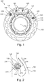
- Fig. 1 shows a centrifugal pendulum 100, which is particularly adapted for use in the drive train of a motor vehicle.
- the centrifugal pendulum 100 comprises a pendulum flange 105 which is rotatably mounted about a rotation axis 110, and a pendulum mass 115, which is mounted in the plane of rotation about the rotation axis 110 slidably on the pendulum flange 105.
- the pendulum mass 115 is shown transparent to better represent its bearing on the pendulum flange 105.
- the pendulum mass 115 includes two pendulum members 120 mounted on different axial sides of the pendulum flange 105
- other embodiments are possible, for example asymmetrical to the pendulum flange 105th
- the pendulum elements 120 are connected to each other by means of one or more bolts 125.
- Each pin 125 extends in the axial direction through a corresponding recess 130 of the pendulum flange 105.
- Limitations of the recesses 130 are usually selected so that the pendulum track of the pendulum mass 115 on the pendulum flange 105 by abutment of one or more bolts 125 at the boundary of the corresponding recess 130th is limited. It is common that pendulum tracks of the pendulum mass 115 and another, not shown pendulum mass 115, which is in or opposite to the direction of rotation of the pendulum 105 in the vicinity of the pendulum mass 115, overlap.
- the adjacent pendulum masses 115 can therefore collide with each other when, for example, the pendulum flange 105 is subjected to a strong or nonuniform torsional vibration. In another embodiment, a striking of the pendulum mass 115 on the pendulum flange 105 at the end of the pendulum track done.
- each stop damper 135 is provided to dampen the impact elastic.
- two stop dampers 135 are provided which lie on a circumference about the rotation axis 110 at opposite ends of the pendulum mass 115.
- each stop damper 135 is arranged rotatably about its own axis 140, which runs parallel to the axis of rotation 110 of the pendulum flange 105.
- Fig. 2 shows a detail of the centrifugal pendulum 100 in the region of the stop damper 135.
- a bolt 125 which connects two pendulum elements 120 of a pendulum mass 115 axially coaxial with the axis of rotation 140 of the stop damper 135.
- the stop damper 135 extends to the Bolt 125 arranged around. It is preferred that the stop damper 135 is rotationally symmetrical.
- the stop damper 135 may comprise a rubber or elastomer disposed in the form of a ring or a hollow cylinder around the bolt 125 or a corresponding element.
- the clearance of the elastomer or rubber is such that there is a predetermined clearance to the bolt 125 to ensure the rotatability of the stopper damper 135.
- a bearing 205 is provided radially between the pin 125 and the stop damper 135.
- the bearing 205 may include, for example, a ball bearing, a sliding bearing or a roller bearing.
- the stop damper 135 further includes a structural member 210 that is radially inward or radially outward of the elastomer or rubber is arranged.
- the structural element 210 may comprise, for example, a metal tire.
- a round shape of the outer surface of the stop damper 135 can be maintained by the structural element 210 even during prolonged operation.
- Radially mounted within the elastomer or rubber, the structural member 210 may increase stability or ensure a resilient transition to the bearing 205 and the bolt 125, respectively.
- the elastomer or rubber may also be arranged radially between two structural elements 210.
- An exemplary abutment point 215 indicates the point on the radially outer surface of the stopper damper 135 at which contact with another element occurs when the pendulum mass 115 strikes in the circumferential direction. If the stop damper 135 is rotated about its axis of rotation 140, the stop point 215 moves over its radially outer surface. In repeated attacks so a statistical equal distribution of the attachment points 215 can be achieved over the surface of the stop damper 135. This also applies if the abutment point 215 changes its position for reasons other than rotation of the stopper damper 135, for example because a stop element is attached to an adjacent pendulum mass whose distance from the axis of rotation 110 is variable.
- a contact surface 220 is provided, along which the stop damper 135 travels, when the pendulum mass 115 is moved on its pendulum track with respect to the pendulum flange 105.
- the stopper damper 135 is rotated when in a direction of collision, but alternatively it may be rotated on its return from the collision.
- the contact surface 220 is formed in the illustrated embodiment by a portion of the boundary of the recess 130 in the pendulum flange 105. In another embodiment, however, the contact surface 220 can also be formed by another element, for example by a stop damper 135 on the adjacent pendulum mass 115.
- the abutment surface 220 is preferably provided such that the pendulum track comprises a first portion 225, on which the stopper damper 135 can freely rotate about its axis of rotation 140, and a second portion 230, on which the abutment surface 220 in lateral engagement with the radially outer surface the stopper damper 135 is.
- the pendulum track of the pendulum mass 115 allows a predetermined radial movement of the pendulum mass 115. This is ensured by the fact that each other in the radial direction opposite Portions of boundaries of the recess 130 are farther apart than the diameter of the stopper damper 135.
- the contact surface 220 is preferably provided only on the radial inside or the radial outside of the stop damper 135. It can thereby be ensured that with an oscillating movement of the pendulum mass 115 with respect to the pendulum flange 105, an engagement between the contact surface 220 and the stop damper 135 takes place only on parts of the movement path, so that the rotation of the stop damper 135 is always briefly effected and then interrupted again. Thereby, an intermittent rotation of the stopper damper 135 can be effected, which assists a statistical equal distribution of the stopper points 215 on the outer circumference of the stopper damper 135.
Description
Die Erfindung betrifft ein Fliehkraftpendel zur Verwendung in einem Antriebsstrang eines Kraftfahrzeugs. Insbesondere betrifft die Erfindung ein Fliehkraftpendel mit einem Anschlagdämpfer zur Begrenzung einer Pendelbahn einer Pendelmasse des Fliehkraftpendels.The invention relates to a centrifugal pendulum for use in a drive train of a motor vehicle. In particular, the invention relates to a centrifugal pendulum with a stop damper for limiting a pendulum track of a pendulum mass of the centrifugal pendulum.
Ein Fliehkraftpendel ist dazu eingerichtet, Drehschwingungen zu tilgen, die einer Drehbewegung einer Übertragungswelle überlagert sein können. Insbesondere im Antriebsstrang eines Kraftfahrzeugs kann ein Hubkolben-Verbrennungsmotor in unterschiedlichen Betriebszuständen Drehschwingungen erzeugen, die vorteilhafterweise getilgt werden, bevor sie über den weiteren Antriebsstrang, der beispielsweise eine Kupplung oder ein Getriebe umfassen kann, in Richtung von Antriebsrädern weiter übertragen werden. Die Drehschwingungen können auch durch Drehungleichförmigkeiten im Bereich der Antriebsräder erzeugt sein und werden vorteilhafterweise getilgt, bevor sie über den Antriebsstrang bis zum Antriebsmotor übertragen werden.A centrifugal pendulum is adapted to eliminate torsional vibrations that may be superimposed on a rotational movement of a transmission shaft. In particular, in the drive train of a motor vehicle, a reciprocating internal combustion engine in different operating conditions generate torsional vibrations, which are advantageously redeemed before they continue to be transmitted in the direction of drive wheels on the other drive train, which may include, for example, a clutch or a transmission. The torsional vibrations can also be generated by rotational irregularities in the region of the drive wheels and are advantageously redeemed before they are transmitted via the drive train to the drive motor.
Ein Fliehkraftpendel, beispielsweise bekannt aus
Aus
In bestimmten Betriebszuständen des Verbrennungsmotors, beispielsweise beim Beschleunigen aus einer niedrigen Drehzahl oder beim Anlassen oder Abstellen des Verbrennungsmotors, kann die Pendelmasse an eine in Umfangsrichtung benachbarte Pendelmasse anschlagen. Dadurch kann ein klapperndes oder rasselndes Geräusch verursacht sein, das von einer Person im Inneren des Kraftfahrzeugs als unangenehm empfunden werden kann. Darüber hinaus können durch das Anschlagen ein Verschleiß oder eine Beschädigung der Pendelmasse bedingt sein. Es ist daher bekannt, einen Anschlagdämpfer vorzusehen, der das Anschlagen benachbarter Pendelmassen am Pendelflansch dämpft.In certain operating conditions of the internal combustion engine, for example when accelerating from a low speed or when starting or stopping the internal combustion engine, the pendulum mass can strike a circumferentially adjacent pendulum mass. As a result, a rattling or rattling noise may be caused, which may be perceived by a person inside the vehicle as unpleasant. In addition, may be due to the impact wear or damage to the pendulum mass. It is therefore known to provide a stop damper which dampens the impact of adjacent pendulum masses on the pendulum flange.
Dabei sind unterschiedliche Vorschläge gemacht worden, um eine langlebige und effiziente Dämpfung des Anschlags zu erzielen. Aufgrund des begrenzten Bauraums und eines wünschenswert einfachen Aufbaus besteht jedoch nach wie vor das Problem, eine effiziente Dämpfung mit einer ausreichenden Lebensdauer des Dämpfungselements zu vereinen. Der Erfindung liegt die Aufgabe zugrunde, dieses Problem zu lösen. Die erfindungsgemäße Lösung besteht in einem Fliehkraftpendel mit den Merkmalen des unabhängigen Anspruchs. Unteransprüche geben bevorzugte Ausführungsformen wieder.Different proposals have been made to achieve a long-lasting and efficient damping of the attack. Due to the limited space and a desirably simple structure, however, there is still the problem of an efficient To combine damping with a sufficient life of the damping element. The invention has for its object to solve this problem. The solution according to the invention consists in a centrifugal pendulum with the features of the independent claim. Subclaims give preferred embodiments again.
Ein erfindungsgemäßes Fliehkraftpendel umfasst einen Pendelflansch, der um eine Drehachse drehbar gelagert ist, eine in der Drehebene beweglich am Pendelflansch angebrachte Pendelmasse und einen an der Pendelmasse angebrachten Anschlagdämpfer zur Begrenzung einer Pendelbahn der Pendelmasse. Dabei ist der Anschlagdämpfer um eine eigene Achse, die parallel zur Drehachse des Pendelflanschs verläuft, drehbar gelagert.A centrifugal pendulum according to the invention comprises a pendulum flange which is rotatably mounted about a rotation axis, a pendulum mass movably mounted on the pendulum flange in the plane of rotation and a stop damper attached to the pendulum mass for limiting a pendulum track of the pendulum mass. In this case, the stop damper is rotatably mounted about its own axis which is parallel to the axis of rotation of the pendulum.
Durch die drehbare Lagerung ist es möglich, eine Abnutzung, einen Verschleiß oder eine Beschädigung des Anschlagdämpfers auf seinen Umfang zu verteilen. Das Anschlagen des Anschlagdämpfers erfolgt stets an einem Anschlagpunkt auf seiner Oberfläche, sodass ein Drehen des Anschlagdämpfers diesen Punkt im Lauf der Zeit um die Drehachse des Anschlagdämpfers über seine Oberfläche wandern lässt. Die bezüglich eines Verschleißes effektiv zur Verfügung stehende Oberfläche des Anschlagdämpfers kann dadurch vergrößert sein. Auf diese Weise kann die Lebensdauer des Anschlagdämpfers verlängert werden. Die Anschlagpunkte können statistisch über die Oberfläche des Anschlagdämpfers gleich verteilt sein, sodass ein über den Umfang des Anschlagdämpfers gleichmäßiger Verschleiß erzielt werden kann.Due to the rotatable mounting, it is possible to distribute wear, wear or damage to the stop damper on its circumference. The abutment of the stop damper always takes place at a stop point on its surface, so that turning the stop damper can move this point over time about the axis of rotation of the stop damper over its surface. The effectively available with respect to wear surface of the stop damper can be increased. In this way, the life of the stop damper can be extended. The attachment points can be distributed statistically over the surface of the stop damper, so that over the circumference of the stop damper even wear can be achieved.
Bevorzugterweise umfasst die Pendelmasse zwei Pendelelemente, die auf unterschiedlichen axialen Seiten des Pendelflanschs liegen und mittels eines axialen Bolzens miteinander verbunden sind, wobei der Anschlagdämpfer um den Bolzen drehbar gelagert ist.Preferably, the pendulum mass comprises two pendulum elements, which lie on different axial sides of the pendulum and are connected to each other by means of an axial bolt, wherein the stop damper is rotatably mounted about the bolt.
Ein derartiger Aufbau der Pendelmasse aus zwei Pendelelementen ist bekannt und wohlerprobt. Durch die Anordnung des Anschlagdämpfers auf dem ohnehin erforderlichen axialen Bolzen kann der Anschlagdämpfer einfach und Platz sparend an der Pendelmasse angebracht sein.Such a construction of the pendulum mass of two pendulum elements is known and well rehearsed. Due to the arrangement of the stop damper on the already required axial bolt the stop damper can be mounted easily and space saving on the pendulum mass.
Erfindungsgemäß ist eine Anlagefläche vorgesehen, an der der Anschlagdämpfer entlang läuft, wenn die Pendelmasse in der Drehebene bewegt wird. Gerät der drehbare Anschlagdämpfer in Eingriff mit der Anlagefläche, während die Pendelmasse bezüglich des Pendelflanschs bewegt wird, so wird ein Drehmoment bewirkt, das den Anschlagdämpfer in Drehung um seine eigene Achse versetzt. Dadurch kann ein Anschlagpunkt des Anschlagdämpfers auf seinem Umfang versetzt werden. Der Anschlagpunkt kann durch eine in der Drehebene benachbarte Pendelmasse, durch einen mit der anderen Pendelmasse verbundenen weiteren Anschlagdämpfer oder ein anderes Anschlagelement gebildet sein, das wahlweise an der anderen Pendelmasse oder am Pendelflansch befestigt ist. Durch das Drehen des Anschlagdämpfers können ein einseitiger Verschleiß und eine rasche Abnutzung verhindert werden.According to the invention, a contact surface is provided on which the stop damper runs along when the pendulum mass is moved in the plane of rotation. Device of the rotatable stop damper in engagement with the abutment surface, while the pendulum mass is moved with respect to the pendulum, so a torque is effected, which sets the stop damper in rotation about its own axis. As a result, an attachment point of the stop damper on its scope are offset. The anchor point may be formed by a pendulum mass adjacent to the plane of rotation, by another stop damper connected to the other pendulum mass, or another stop element which is selectively attached to the other pendulum mass or to the pendulum flange. By turning the stop damper, one-sided wear and rapid wear can be prevented.
Bevorzugterweise verläuft der Bolzen durch eine Aussparung im Pendelflansch, wobei die Anlagefläche einen Abschnitt der Begrenzung der Aussparung umfasst. So kann die Relativbewegung der Pendelmasse bezüglich des Pendelflanschs auf der Pendelbahn dazu ausgenutzt werden, den Anschlagdämpfer um seine eigene Achse zu drehen. In einer anderen Ausführungsform kann die Anlagefläche auch beispielsweise durch die benachbarte Pendelmasse oder ein mit ihr verbundenes Element gebildet sein.Preferably, the bolt passes through a recess in the pendulum, wherein the contact surface comprises a portion of the boundary of the recess. Thus, the relative movement of the pendulum mass with respect to the pendulum on the pendulum can be exploited to turn the damper about its own axis. In another embodiment, the contact surface may also be formed, for example, by the adjacent pendulum mass or an element connected to it.
Die Pendelbahn der Pendelmasse am Pendelflansch weist einen ersten Abschnitt auf, auf dem der Anschlagdämpfer frei drehbar ist, und einen zweiten Abschnitt, auf dem die Anlagefläche lateral in den Anschlagdämpfer eingreift. Anders ausgedrückt kann der Eingriff der Anlagefläche mit dem Anschlagdämpfer auf einen Teil der Pendelbahn beschränkt sein, während auf einem anderen Teil kein Eingriff erfolgt. Dadurch kann vermieden werden, dass der Anschlagdämpfer um gleiche Beträge vorwärts und rückwärts gedreht wird, wenn sich die Pendelmasse am Pendelflansch oszillierend bewegt. Dadurch kann verbessert sichergestellt sein, dass der Anschlagpunkt des Anschlagdämpfers entlang dessen Oberfläche versetzt wird.The pendulum track of the pendulum mass on the pendulum has a first portion on which the stop damper is freely rotatable, and a second portion on which engages the contact surface laterally in the stop damper. In other words, the engagement of the abutment surface with the stop damper may be restricted to one part of the pendulum track while no engagement takes place on another part. This can be avoided that the stop damper is rotated by equal amounts forward and backward when the pendulum mass moves oscillating on the pendulum. This can be improved to ensure that the attachment point of the stop damper is offset along the surface thereof.
In einer Ausführungsform ist die Anlagefläche bezüglich der Drehachse des Pendelflanschs nur radial innen oder nur radial außen vorgesehen. Die Pendelmasse ist auf der Pendelbahn üblicherweise radial innen und radial außen geführt, wobei zwischen den Führungen ein vorbestimmtes Spiel oder ein vorbestimmter Bewegungsraum existiert. Insbesondere kann vorgesehen sein, dass die Pendelmasse unterschiedliche Abstände von ihrer Drehachse aufweist, etwa in Abhängigkeit einer Bewegungsrichtung gegenüber dem Pendelflansch. Durch das Vorsehen der Anlagefläche nur radial innen oder nur radial außen kann sichergestellt werden, dass die Drehung des Anschlagelements nur dann erfolgt, wenn die entsprechende innere bzw. äußere radiale Führung eingreift. Bei einer oszillierenden Bewegung der Pendelmasse am Pendelflansch können insbesondere alternierend die innere und die äußere Führung eingreifen. die Abfolge zwischen freier Drehung und Drehbeschleunigung des Anschlagelements durch Eingriff der Anlagefläche kann dadurch gezielt gesteuert sein.In one embodiment, the contact surface with respect to the axis of rotation of the pendulum is provided only radially inward or radially outward. The pendulum mass is usually performed on the pendulum track radially inside and radially outside, between the guides a predetermined game or a predetermined range of motion exists. In particular, it can be provided that the pendulum mass has different distances from its axis of rotation, for example as a function of a direction of movement relative to the pendulum flange. By providing the contact surface only radially inward or radially outward, it can be ensured that the rotation of the stop element takes place only when the corresponding inner or outer radial guide engages. In the case of an oscillating movement of the pendulum mass on the pendulum flange, in particular the inner and outer guides can intervene alternately. the sequence between free rotation and rotational acceleration of the stop element by engagement of the contact surface can be selectively controlled.
Ferner ist bevorzugt, dass die Pendelbahn der Pendelmasse durch die Anlage des Anschlagdämpfers an der Begrenzung der Aussparung begrenzt ist. Die Definition der Pendelbahn am Pendelflansch kann so teilweise durch den drehbaren Anschlagdämpfer übernommen werden. So kann eine Mehrfachnutzung von Elementen des Fliehkraftpendels erzielt werden, wodurch Gewicht, Material und Kosten eingespart werden können.Furthermore, it is preferred that the pendulum track of the pendulum mass is limited by the abutment of the stopper damper at the boundary of the recess. The definition of the pendulum track on the pendulum flange can thus be partially taken over by the rotatable stop damper. Thus, a multiple use of elements of the centrifugal pendulum can be achieved, which weight, material and cost can be saved.
Es ist weiter bevorzugt, dass der Anschlagdämpfer rotationssymmetrisch um seine Achse aufgebaut ist. Dadurch kann eine gleichmäßige Verteilung des Anschlagpunkts über die Oberfläche des Anschlagdämpfers erzielt werden. Dabei umfasst der Anschlagdämpfer üblicherweise ein Elastomer oder einen Gummi, der in Form eines Rings oder eines Hohlzylinders um die Achse des Anschlagdämpfers angeordnet ist.It is further preferred that the stop damper is constructed rotationally symmetrical about its axis. As a result, a uniform distribution of the attachment point over the surface of the stop damper can be achieved. In this case, the stop damper usually comprises an elastomer or a rubber, which is arranged in the form of a ring or a hollow cylinder about the axis of the stop damper.
Zur Drehung des Anschlagdämpfers um seine Achse kann ein Lager vorgesehen sein. In einer einfachen Ausführungsform kann ein vorbestimmtes radiales Spiel zwischen dem Elastomer bzw. Gummi und einer mit der Pendelmasse verbundenen Achse, etwa des oben beschriebenen Bolzens, bestehen, so dass eine gleichmäßige Drehbarkeit des Anschlagdämpfers gewährleistet ist. In einer anderen Ausführungsform kann beispielsweise ein Kugel-, Rollen- oder Gleitlager zwischen dem Anschlagdämpfer und der Achse eingesetzt sein.For rotation of the stop damper about its axis, a bearing may be provided. In a simple embodiment, a predetermined radial clearance between the elastomer or rubber and an axis connected to the pendulum mass, such as the bolt described above, exist, so that a uniform rotation of the stop damper is ensured. In another embodiment, for example, a ball, roller or sliding bearing between the stop damper and the axle be used.
Die Erfindung wird nun mit Bezug auf die beigefügten Figuren genauer beschrieben, in denen:
- Fig. 1
- eine schematische Darstellung eines Fliehkraftpendels, und
- Fig. 2
- einen Anschlagdämpfer des Fliehkraftpendels von
Fig. 1
- Fig. 1
- a schematic representation of a centrifugal pendulum, and
- Fig. 2
- a stop damper of the centrifugal pendulum of
Fig. 1
Die Pendelelemente 120 sind mittels eines oder mehrerer Bolzen 125 miteinander verbunden. Jeder Bolzen 125 erstreckt sich in axialer Richtung durch eine korrespondierende Aussparung 130 des Pendelflanschs 105. Dabei sind Begrenzungen der Aussparungen 130 üblicherweise so gewählt, dass die Pendelbahn der Pendelmasse 115 am Pendelflansch 105 durch Anliegen eines oder mehrerer Bolzen 125 an der Begrenzung der korrespondierenden Aussparung 130 begrenzt ist. Es ist üblich, dass sich Pendelbahnen der Pendelmasse 115 und einer weiteren, nicht dargestellten Pendelmasse 115, die in oder entgegen der Drehrichtung des Pendelflanschs 105 in Nachbarschaft zur Pendelmasse 115 liegt, überlappen. Die benachbarten Pendelmassen 115 können daher miteinander kollidieren, wenn beispielsweise der Pendelflansch 105 einer starken oder ungleichförmigen Drehschwingung ausgesetzt ist. In einer anderen Ausführungsform kann auch ein Anschlagen der Pendelmasse 115 am Pendelflansch 105 am Ende der Pendelbahn erfolgen.The
Um das Anschlagen elastisch zu bedämpfen, ist wenigstens ein Anschlagdämpfer 135 vorgesehen. In der dargestellten Ausführungsform sind zwei Anschlagdämpfer 135 vorgesehen, die auf einem Umfang um die Drehachse 110 an entgegengesetzten Enden der Pendelmasse 115 liegen. Dabei ist jeder Anschlagdämpfer 135 um eine eigene Achse 140, die parallel zur Drehachse 110 des Pendelflanschs 105 verläuft, drehbar angeordnet.To dampen the impact elastic, at least one
Ein exemplarischer Anschlagpunkt 215 kennzeichnet den Punkt an der radial äußeren Oberfläche des Anschlagdämpfers 135, an dem ein Kontakt mit einem anderen Element erfolgt, wenn die Pendelmasse 115 in Umfangrichtung anschlägt. Wird der Anschlagdämpfer 135 um seine Drehachse 140 gedreht, wandert der Anschlagpunkt 215 über seine radial äußere Oberfläche. Bei wiederholten Anschlägen kann so eine statistische Gleichverteilung der Anschlagpunkte 215 über die Oberfläche des Anschlagdämpfers 135 erzielt werden. Dies gilt auch dann, wenn der Anschlagpunkt 215 aus anderen Gründen als durch Drehung des Anschlagdämpfers 135 seine Position ändert, beispielsweise weil ein anschlagendes Element an einer benachbarten Pendelmasse angebracht ist, deren Abstand zur Drehachse 110 veränderlich ist.An
Um das Drehen des Anschlagdämpfers 135 zu gewährleisten, ist eine Anlagefläche 220 vorgesehen, an der der Anschlagdämpfer 135 entlangläuft, wenn die Pendelmasse 115 auf ihrer Pendelbahn bezüglich des Pendelflanschs 105 bewegt wird. Bevorzugterweise wird der Anschlagdämpfer 135 gedreht, wenn er sich in einer Bewegung in Richtung Kollision befindet, alternativ dazu kann er jedoch auch auf seinem Rückweg von der Kollision gedreht werden. Die Anlagefläche 220 wird in der dargestellten Ausführungsform durch einen Abschnitt der Begrenzung der Aussparung 130 im Pendelflansch 105 gebildet. In einer anderen Ausführungsform kann die Anlagefläche 220 jedoch auch durch ein anderes Element gebildet werden, beispielsweise durch einen Anschlagdämpfer 135 an der benachbarten Pendelmasse 115.In order to ensure the rotation of the
Die Anlagefläche 220 ist bevorzugterweise so vorgesehen, dass die Pendelbahn einen ersten Abschnitt 225 umfasst, auf dem sich der Anschlagdämpfer 135 um seine Drehachse 140 frei drehen kann, und einen zweiten Abschnitt 230, auf dem die Anlagefläche 220 in lateralen Eingriff mit der radial äußeren Oberfläche des Anschlagdämpfers 135 ist.The
Die Pendelbahn der Pendelmasse 115 erlaubt eine vorbestimmte radiale Bewegung der Pendelmasse 115. Dies ist dadurch sichergestellt, dass einander in radialer Richtung gegenüberliegende Abschnitte von Begrenzungen der Aussparung 130 weiter voneinander entfernt sind als der Durchmesser des Anschlagdämpfers 135 beträgt. Dabei ist die Anlagefläche 220 bevorzugterweise nur auf der radialen Innenseite oder der radialen Außenseite des Anschlagdämpfers 135 vorgesehen. Dadurch kann sichergestellt werden, dass bei einer oszillierenden Bewegung der Pendelmasse 115 bezüglich des Pendelflanschs 105 ein Eingriff zwischen der Anlagefläche 220 und dem Anschlagdämpfer 135 nur auf Teilen der Bewegungsbahn erfolgt, sodass die Drehung des Anschlagdämpfers 135 immer wieder kurz bewirkt und dann wieder unterbrochen wird. Dadurch kann ein intermittierendes Drehen des Anschlagdämpfers 135 bewirkt werden, der eine statistische Gleichverteilung der Anschlagpunkte 215 auf dem äußeren Umfang des Anschlagdämpfers 135 unterstützt.The pendulum track of the
- 100100
- Fliehkraftpendelcentrifugal pendulum
- 105105
- Pendelflanschpendulum
- 110110
- Drehachseaxis of rotation
- 115115
- Pendelmassependulum mass
- 120120
- Pendelelementshuttle
- 125125
- Bolzenbolt
- 130130
- Aussparungrecess
- 135135
- Anschlagdämpferstop damper
- 140140
- Drehachse des AnschlagdämpfersRotary axis of the stop damper
- 205205
- Lagerwarehouse
- 210210
- Strukturelementstructural element
- 215215
- Anschlagpunktanchorage point
- 220220
- Anlageflächecontact surface
- 225225
- erster Abschnitt der Pendelbahnfirst section of the aerial tramway
- 230230
- zweiter Abschnitt der Pendelbahnsecond section of the aerial tramway
Claims (7)
- Centrifugal force pendulum (100), comprising:- a pendulum flange (105) which is mounted such that it can be rotated about a rotational axis (110);- a pendulum mass (115) which is attached to the pendulum flange (105) such that it can be moved in the rotational plane;- a stop damper (135) which is attached to the pendulum mass (115) for limiting a pendulum path of the pendulum mass (115),- the stop damper (135) being mounted such that it can be rotated about its own axis (140) which runs parallel to the rotational axis (110) of the pendulum flange (105), characterized in that a bearing face (220) is provided, along which the stop damper (135) runs when the pendulum mass (115) is moved in the rotational plane, the pendulum path of the pendulum mass (115) on the pendulum flange (105) comprising a first section (225), on which the stop damper (135) can be rotated freely, and a second section (230), on which the bearing face (220) engages laterally into the stop damper (135), whereby the stop point of the stop damper is moved along its surface.
- Centrifugal force pendulum (100) according to Claim 1, the pendulum mass (115) comprising two pendulum elements (120) which lie on different axial sides of the pendulum flange (105) and are connected to one another by means of an axial pin (125), and the stop damper (135) being mounted such that it can be rotated about the pin (125).
- Centrifugal force pendulum (100) according to Claim 1, the pin (125) running through a cut-out (130) in the pendulum flange (105), and the bearing face (220) comprising a section of the border of the cut-out (130).
- Centrifugal force pendulum (100) according to one of the preceding claims, the bearing face (220) being provided merely radially on the inside or merely radially on the outside with regard to the rotational axis (110) of the pendulum flange (105).
- Centrifugal force pendulum (100) according to one of the preceding claims, the pendulum path being limited by way of the contact of the stop damper (135) with the boundary of the cut-out (130).
- Centrifugal force pendulum (100) according to one of the preceding claims, the stop damper (135) being of rotationally symmetrical construction about its axis (140).
- Centrifugal force pendulum (100) according to one of the preceding claims, a bearing (205) for rotating the stop damper (135) about its axis (140) being provided.
Applications Claiming Priority (2)
| Application Number | Priority Date | Filing Date | Title |
|---|---|---|---|
| DE102013219394 | 2013-09-26 | ||
| PCT/DE2014/200432 WO2015043588A1 (en) | 2013-09-26 | 2014-08-29 | Centrifugal force pendulum having an impact damper |
Publications (2)
| Publication Number | Publication Date |
|---|---|
| EP3049691A1 EP3049691A1 (en) | 2016-08-03 |
| EP3049691B1 true EP3049691B1 (en) | 2019-07-24 |
Family
ID=51609878
Family Applications (1)
| Application Number | Title | Priority Date | Filing Date |
|---|---|---|---|
| EP14772058.5A Active EP3049691B1 (en) | 2013-09-26 | 2014-08-29 | Centrifugal force pendulum having an impact damper |
Country Status (4)
| Country | Link |
|---|---|
| EP (1) | EP3049691B1 (en) |
| CN (1) | CN105579739B (en) |
| DE (2) | DE112014004460A5 (en) |
| WO (1) | WO2015043588A1 (en) |
Families Citing this family (1)
| Publication number | Priority date | Publication date | Assignee | Title |
|---|---|---|---|---|
| WO2018199324A1 (en) * | 2017-04-28 | 2018-11-01 | アイシン・エィ・ダブリュ株式会社 | Vibration damping device |
Family Cites Families (6)
| Publication number | Priority date | Publication date | Assignee | Title |
|---|---|---|---|---|
| CN1077257A (en) * | 1992-04-11 | 1993-10-13 | 西安交通大学 | Increase steady method of slight and the device thereof of pressing down |
| US5941133A (en) * | 1996-04-19 | 1999-08-24 | Eti Technologies Inc. | Torsional and translational vibration removing device |
| DE102004011830B4 (en) * | 2003-03-14 | 2015-09-03 | Schaeffler Technologies AG & Co. KG | torsional vibration dampers |
| DE102011102812A1 (en) * | 2010-06-14 | 2011-12-15 | Schaeffler Technologies Gmbh & Co. Kg | Centrifugal pendulum device |
| CN103097765B (en) * | 2010-09-08 | 2014-12-10 | 爱信艾达工业株式会社 | Dynamic vibration absorber |
| DE102012219798A1 (en) * | 2011-11-11 | 2013-05-16 | Schaeffler Technologies AG & Co. KG | Centrifugal force pendulum device for use in two-mass flywheel to compensate rotational non-uniformities in powertrain of combustion engine-driven motor car, has flange section with fixation element for arranging at another flange section |
-
2014
- 2014-08-29 DE DE112014004460.1T patent/DE112014004460A5/en not_active Withdrawn
- 2014-08-29 CN CN201480052972.3A patent/CN105579739B/en active Active
- 2014-08-29 EP EP14772058.5A patent/EP3049691B1/en active Active
- 2014-08-29 WO PCT/DE2014/200432 patent/WO2015043588A1/en active Application Filing
- 2014-08-29 DE DE201410217254 patent/DE102014217254A1/en not_active Withdrawn
Non-Patent Citations (1)
| Title |
|---|
| None * |
Also Published As
| Publication number | Publication date |
|---|---|
| WO2015043588A1 (en) | 2015-04-02 |
| DE102014217254A1 (en) | 2015-03-26 |
| CN105579739A (en) | 2016-05-11 |
| DE112014004460A5 (en) | 2016-06-02 |
| EP3049691A1 (en) | 2016-08-03 |
| CN105579739B (en) | 2018-06-08 |
Similar Documents
| Publication | Publication Date | Title |
|---|---|---|
| EP2976546B1 (en) | Tuned mass damper | |
| DE3448510C2 (en) | IC engine torque variation compensator | |
| EP2786042B1 (en) | Centrifugal force pendulum | |
| DE112014000773B4 (en) | centrifugal pendulum device | |
| DE102009037481B4 (en) | Speed-adaptive absorber, in particular centrifugal pendulum device | |
| EP2850338B1 (en) | Centrifugal-force pendulum | |
| EP2935936B1 (en) | Centrifugal force pendulum device, and drive train of a motor vehicle | |
| WO2015028233A1 (en) | Absorber system | |
| DE19911560A1 (en) | Automotive transmission shaft mass balance vibration dampener | |
| WO2015032398A1 (en) | Centrifugal pendulum stop spring element, centrifugal pendulum device and component arrangement | |
| DE102013213008A1 (en) | A torsional vibration damper | |
| DE102014216752A1 (en) | Centrifugal pendulum device | |
| EP3283787A1 (en) | Centrifugal pendulum | |
| DE102013106291A1 (en) | vibration absorber | |
| EP3622196B1 (en) | Centrifugal pendulum device having a pre-stressing element for guiding the cylindrical rollers | |
| EP3049691B1 (en) | Centrifugal force pendulum having an impact damper | |
| DE102013217091A1 (en) | absorber system | |
| DE102013220287A1 (en) | centrifugal pendulum | |
| EP3172460A1 (en) | Centrifugal pendulum and drive system having a centrifugal pendulum | |
| DE102015215907A1 (en) | centrifugal pendulum | |
| DE102014221689A1 (en) | Pendulum mass for a centrifugal pendulum | |
| DE102014203061A1 (en) | Centrifugal pendulum and drive system with centrifugal pendulum | |
| DE102017123073A1 (en) | Centrifugal pendulum with a friction- and noise-optimized pendulum receiver | |
| DE102020112386A1 (en) | Centrifugal pendulum | |
| DE102019128146A1 (en) | Centrifugal pendulum device and torque transmission device |
Legal Events
| Date | Code | Title | Description |
|---|---|---|---|
| PUAI | Public reference made under article 153(3) epc to a published international application that has entered the european phase |
Free format text: ORIGINAL CODE: 0009012 |
|
| 17P | Request for examination filed |
Effective date: 20160426 |
|
| AK | Designated contracting states |
Kind code of ref document: A1 Designated state(s): AL AT BE BG CH CY CZ DE DK EE ES FI FR GB GR HR HU IE IS IT LI LT LU LV MC MK MT NL NO PL PT RO RS SE SI SK SM TR |
|
| AX | Request for extension of the european patent |
Extension state: BA ME |
|
| RIN1 | Information on inventor provided before grant (corrected) |
Inventor name: DINGER, CHRISTIAN |
|
| DAX | Request for extension of the european patent (deleted) | ||
| GRAP | Despatch of communication of intention to grant a patent |
Free format text: ORIGINAL CODE: EPIDOSNIGR1 |
|
| STAA | Information on the status of an ep patent application or granted ep patent |
Free format text: STATUS: GRANT OF PATENT IS INTENDED |
|
| INTG | Intention to grant announced |
Effective date: 20190213 |
|
| GRAS | Grant fee paid |
Free format text: ORIGINAL CODE: EPIDOSNIGR3 |
|
| GRAA | (expected) grant |
Free format text: ORIGINAL CODE: 0009210 |
|
| STAA | Information on the status of an ep patent application or granted ep patent |
Free format text: STATUS: THE PATENT HAS BEEN GRANTED |
|
| AK | Designated contracting states |
Kind code of ref document: B1 Designated state(s): AL AT BE BG CH CY CZ DE DK EE ES FI FR GB GR HR HU IE IS IT LI LT LU LV MC MK MT NL NO PL PT RO RS SE SI SK SM TR |
|
| REG | Reference to a national code |
Ref country code: GB Ref legal event code: FG4D Free format text: NOT ENGLISH |
|
| REG | Reference to a national code |
Ref country code: CH Ref legal event code: EP |
|
| REG | Reference to a national code |
Ref country code: DE Ref legal event code: R096 Ref document number: 502014012288 Country of ref document: DE |
|
| REG | Reference to a national code |
Ref country code: AT Ref legal event code: REF Ref document number: 1158569 Country of ref document: AT Kind code of ref document: T Effective date: 20190815 |
|
| REG | Reference to a national code |
Ref country code: IE Ref legal event code: FG4D Free format text: LANGUAGE OF EP DOCUMENT: GERMAN |
|
| REG | Reference to a national code |
Ref country code: NL Ref legal event code: MP Effective date: 20190724 |
|
| REG | Reference to a national code |
Ref country code: LT Ref legal event code: MG4D |
|
| PG25 | Lapsed in a contracting state [announced via postgrant information from national office to epo] |
Ref country code: BG Free format text: LAPSE BECAUSE OF FAILURE TO SUBMIT A TRANSLATION OF THE DESCRIPTION OR TO PAY THE FEE WITHIN THE PRESCRIBED TIME-LIMIT Effective date: 20191024 Ref country code: LT Free format text: LAPSE BECAUSE OF FAILURE TO SUBMIT A TRANSLATION OF THE DESCRIPTION OR TO PAY THE FEE WITHIN THE PRESCRIBED TIME-LIMIT Effective date: 20190724 Ref country code: HR Free format text: LAPSE BECAUSE OF FAILURE TO SUBMIT A TRANSLATION OF THE DESCRIPTION OR TO PAY THE FEE WITHIN THE PRESCRIBED TIME-LIMIT Effective date: 20190724 Ref country code: PT Free format text: LAPSE BECAUSE OF FAILURE TO SUBMIT A TRANSLATION OF THE DESCRIPTION OR TO PAY THE FEE WITHIN THE PRESCRIBED TIME-LIMIT Effective date: 20191125 Ref country code: NL Free format text: LAPSE BECAUSE OF FAILURE TO SUBMIT A TRANSLATION OF THE DESCRIPTION OR TO PAY THE FEE WITHIN THE PRESCRIBED TIME-LIMIT Effective date: 20190724 Ref country code: SE Free format text: LAPSE BECAUSE OF FAILURE TO SUBMIT A TRANSLATION OF THE DESCRIPTION OR TO PAY THE FEE WITHIN THE PRESCRIBED TIME-LIMIT Effective date: 20190724 Ref country code: FI Free format text: LAPSE BECAUSE OF FAILURE TO SUBMIT A TRANSLATION OF THE DESCRIPTION OR TO PAY THE FEE WITHIN THE PRESCRIBED TIME-LIMIT Effective date: 20190724 Ref country code: NO Free format text: LAPSE BECAUSE OF FAILURE TO SUBMIT A TRANSLATION OF THE DESCRIPTION OR TO PAY THE FEE WITHIN THE PRESCRIBED TIME-LIMIT Effective date: 20191024 |
|
| PG25 | Lapsed in a contracting state [announced via postgrant information from national office to epo] |
Ref country code: ES Free format text: LAPSE BECAUSE OF FAILURE TO SUBMIT A TRANSLATION OF THE DESCRIPTION OR TO PAY THE FEE WITHIN THE PRESCRIBED TIME-LIMIT Effective date: 20190724 Ref country code: RS Free format text: LAPSE BECAUSE OF FAILURE TO SUBMIT A TRANSLATION OF THE DESCRIPTION OR TO PAY THE FEE WITHIN THE PRESCRIBED TIME-LIMIT Effective date: 20190724 Ref country code: IS Free format text: LAPSE BECAUSE OF FAILURE TO SUBMIT A TRANSLATION OF THE DESCRIPTION OR TO PAY THE FEE WITHIN THE PRESCRIBED TIME-LIMIT Effective date: 20191124 Ref country code: GR Free format text: LAPSE BECAUSE OF FAILURE TO SUBMIT A TRANSLATION OF THE DESCRIPTION OR TO PAY THE FEE WITHIN THE PRESCRIBED TIME-LIMIT Effective date: 20191025 Ref country code: AL Free format text: LAPSE BECAUSE OF FAILURE TO SUBMIT A TRANSLATION OF THE DESCRIPTION OR TO PAY THE FEE WITHIN THE PRESCRIBED TIME-LIMIT Effective date: 20190724 Ref country code: LV Free format text: LAPSE BECAUSE OF FAILURE TO SUBMIT A TRANSLATION OF THE DESCRIPTION OR TO PAY THE FEE WITHIN THE PRESCRIBED TIME-LIMIT Effective date: 20190724 |
|
| PG25 | Lapsed in a contracting state [announced via postgrant information from national office to epo] |
Ref country code: TR Free format text: LAPSE BECAUSE OF FAILURE TO SUBMIT A TRANSLATION OF THE DESCRIPTION OR TO PAY THE FEE WITHIN THE PRESCRIBED TIME-LIMIT Effective date: 20190724 |
|
| PG25 | Lapsed in a contracting state [announced via postgrant information from national office to epo] |
Ref country code: IT Free format text: LAPSE BECAUSE OF FAILURE TO SUBMIT A TRANSLATION OF THE DESCRIPTION OR TO PAY THE FEE WITHIN THE PRESCRIBED TIME-LIMIT Effective date: 20190724 Ref country code: RO Free format text: LAPSE BECAUSE OF FAILURE TO SUBMIT A TRANSLATION OF THE DESCRIPTION OR TO PAY THE FEE WITHIN THE PRESCRIBED TIME-LIMIT Effective date: 20190724 Ref country code: EE Free format text: LAPSE BECAUSE OF FAILURE TO SUBMIT A TRANSLATION OF THE DESCRIPTION OR TO PAY THE FEE WITHIN THE PRESCRIBED TIME-LIMIT Effective date: 20190724 Ref country code: DK Free format text: LAPSE BECAUSE OF FAILURE TO SUBMIT A TRANSLATION OF THE DESCRIPTION OR TO PAY THE FEE WITHIN THE PRESCRIBED TIME-LIMIT Effective date: 20190724 Ref country code: PL Free format text: LAPSE BECAUSE OF FAILURE TO SUBMIT A TRANSLATION OF THE DESCRIPTION OR TO PAY THE FEE WITHIN THE PRESCRIBED TIME-LIMIT Effective date: 20190724 |
|
| PG25 | Lapsed in a contracting state [announced via postgrant information from national office to epo] |
Ref country code: CZ Free format text: LAPSE BECAUSE OF FAILURE TO SUBMIT A TRANSLATION OF THE DESCRIPTION OR TO PAY THE FEE WITHIN THE PRESCRIBED TIME-LIMIT Effective date: 20190724 Ref country code: CH Free format text: LAPSE BECAUSE OF NON-PAYMENT OF DUE FEES Effective date: 20190831 Ref country code: SK Free format text: LAPSE BECAUSE OF FAILURE TO SUBMIT A TRANSLATION OF THE DESCRIPTION OR TO PAY THE FEE WITHIN THE PRESCRIBED TIME-LIMIT Effective date: 20190724 Ref country code: MC Free format text: LAPSE BECAUSE OF FAILURE TO SUBMIT A TRANSLATION OF THE DESCRIPTION OR TO PAY THE FEE WITHIN THE PRESCRIBED TIME-LIMIT Effective date: 20190724 Ref country code: IS Free format text: LAPSE BECAUSE OF FAILURE TO SUBMIT A TRANSLATION OF THE DESCRIPTION OR TO PAY THE FEE WITHIN THE PRESCRIBED TIME-LIMIT Effective date: 20200224 Ref country code: SM Free format text: LAPSE BECAUSE OF FAILURE TO SUBMIT A TRANSLATION OF THE DESCRIPTION OR TO PAY THE FEE WITHIN THE PRESCRIBED TIME-LIMIT Effective date: 20190724 Ref country code: LU Free format text: LAPSE BECAUSE OF NON-PAYMENT OF DUE FEES Effective date: 20190829 Ref country code: LI Free format text: LAPSE BECAUSE OF NON-PAYMENT OF DUE FEES Effective date: 20190831 |
|
| REG | Reference to a national code |
Ref country code: BE Ref legal event code: MM Effective date: 20190831 |
|
| REG | Reference to a national code |
Ref country code: DE Ref legal event code: R097 Ref document number: 502014012288 Country of ref document: DE |
|
| PLBE | No opposition filed within time limit |
Free format text: ORIGINAL CODE: 0009261 |
|
| STAA | Information on the status of an ep patent application or granted ep patent |
Free format text: STATUS: NO OPPOSITION FILED WITHIN TIME LIMIT |
|
| PG2D | Information on lapse in contracting state deleted |
Ref country code: IS |
|
| PG25 | Lapsed in a contracting state [announced via postgrant information from national office to epo] |
Ref country code: IE Free format text: LAPSE BECAUSE OF NON-PAYMENT OF DUE FEES Effective date: 20190829 |
|
| 26N | No opposition filed |
Effective date: 20200603 |
|
| PG25 | Lapsed in a contracting state [announced via postgrant information from national office to epo] |
Ref country code: SI Free format text: LAPSE BECAUSE OF FAILURE TO SUBMIT A TRANSLATION OF THE DESCRIPTION OR TO PAY THE FEE WITHIN THE PRESCRIBED TIME-LIMIT Effective date: 20190724 Ref country code: BE Free format text: LAPSE BECAUSE OF NON-PAYMENT OF DUE FEES Effective date: 20190831 |
|
| GBPC | Gb: european patent ceased through non-payment of renewal fee |
Effective date: 20191024 |
|
| REG | Reference to a national code |
Ref country code: AT Ref legal event code: MM01 Ref document number: 1158569 Country of ref document: AT Kind code of ref document: T Effective date: 20190829 |
|
| PG25 | Lapsed in a contracting state [announced via postgrant information from national office to epo] |
Ref country code: GB Free format text: LAPSE BECAUSE OF NON-PAYMENT OF DUE FEES Effective date: 20191024 |
|
| PG25 | Lapsed in a contracting state [announced via postgrant information from national office to epo] |
Ref country code: AT Free format text: LAPSE BECAUSE OF NON-PAYMENT OF DUE FEES Effective date: 20190829 |
|
| PG25 | Lapsed in a contracting state [announced via postgrant information from national office to epo] |
Ref country code: CY Free format text: LAPSE BECAUSE OF FAILURE TO SUBMIT A TRANSLATION OF THE DESCRIPTION OR TO PAY THE FEE WITHIN THE PRESCRIBED TIME-LIMIT Effective date: 20190724 |
|
| PG25 | Lapsed in a contracting state [announced via postgrant information from national office to epo] |
Ref country code: HU Free format text: LAPSE BECAUSE OF FAILURE TO SUBMIT A TRANSLATION OF THE DESCRIPTION OR TO PAY THE FEE WITHIN THE PRESCRIBED TIME-LIMIT; INVALID AB INITIO Effective date: 20140829 Ref country code: MT Free format text: LAPSE BECAUSE OF FAILURE TO SUBMIT A TRANSLATION OF THE DESCRIPTION OR TO PAY THE FEE WITHIN THE PRESCRIBED TIME-LIMIT Effective date: 20190724 |
|
| PG25 | Lapsed in a contracting state [announced via postgrant information from national office to epo] |
Ref country code: MK Free format text: LAPSE BECAUSE OF FAILURE TO SUBMIT A TRANSLATION OF THE DESCRIPTION OR TO PAY THE FEE WITHIN THE PRESCRIBED TIME-LIMIT Effective date: 20190724 |
|
| P01 | Opt-out of the competence of the unified patent court (upc) registered |
Effective date: 20230522 |
|
| PGFP | Annual fee paid to national office [announced via postgrant information from national office to epo] |
Ref country code: FR Payment date: 20230825 Year of fee payment: 10 |
|
| PGFP | Annual fee paid to national office [announced via postgrant information from national office to epo] |
Ref country code: DE Payment date: 20231019 Year of fee payment: 10 |