EP3048908B1 - Machine pour la fabrication de filtres composites - Google Patents
Machine pour la fabrication de filtres composites Download PDFInfo
- Publication number
- EP3048908B1 EP3048908B1 EP14789392.9A EP14789392A EP3048908B1 EP 3048908 B1 EP3048908 B1 EP 3048908B1 EP 14789392 A EP14789392 A EP 14789392A EP 3048908 B1 EP3048908 B1 EP 3048908B1
- Authority
- EP
- European Patent Office
- Prior art keywords
- axis
- roller
- conveyor
- groups
- transfer unit
- Prior art date
- Legal status (The legal status is an assumption and is not a legal conclusion. Google has not performed a legal analysis and makes no representation as to the accuracy of the status listed.)
- Active
Links
- 239000002131 composite material Substances 0.000 title claims description 10
- 230000005540 biological transmission Effects 0.000 claims description 24
- 125000006850 spacer group Chemical group 0.000 claims description 11
- 230000000712 assembly Effects 0.000 claims description 6
- 238000000429 assembly Methods 0.000 claims description 6
- 238000001914 filtration Methods 0.000 description 3
- 235000019504 cigarettes Nutrition 0.000 description 2
- 230000000694 effects Effects 0.000 description 1
- 230000009931 harmful effect Effects 0.000 description 1
- 239000000463 material Substances 0.000 description 1
- 230000002093 peripheral effect Effects 0.000 description 1
- 239000000779 smoke Substances 0.000 description 1
- 238000011144 upstream manufacturing Methods 0.000 description 1
Images


Classifications
-
- A—HUMAN NECESSITIES
- A24—TOBACCO; CIGARS; CIGARETTES; SIMULATED SMOKING DEVICES; SMOKERS' REQUISITES
- A24D—CIGARS; CIGARETTES; TOBACCO SMOKE FILTERS; MOUTHPIECES FOR CIGARS OR CIGARETTES; MANUFACTURE OF TOBACCO SMOKE FILTERS OR MOUTHPIECES
- A24D3/00—Tobacco smoke filters, e.g. filter-tips, filtering inserts; Filters specially adapted for simulated smoking devices; Mouthpieces for cigars or cigarettes
- A24D3/02—Manufacture of tobacco smoke filters
- A24D3/0275—Manufacture of tobacco smoke filters for filters with special features
- A24D3/0287—Manufacture of tobacco smoke filters for filters with special features for composite filters
Definitions
- This invention relates to a machine for making composite filters.
- Composite filters are filters obtained by juxtaposing two or more filter sticks having different filtering properties.
- Machines for making filters of this kind comprise one or more combining units capable of feeding a plurality of groups of filter sticks having different filtering properties to a forming beam for forming one or two filter rods.
- these groups of filter sticks are transferred to the forming beam by rotary transfer means typically embodied by rollers equipped with respective pickup elements and/or splined rollers.
- These transfer rollers are driven in rotation by a respective motor unit.
- a group of filter sticks aligned axially with each other is thus formed in each of the pickup elements and/or in each of the grooves on the rollers.
- the groups of filter sticks are then made to move in a direction transversal to their longitudinal axes in order to transfer them to a common receiving conveyor roller, provided with respective peripheral hold-down seats, which feeds the forming beam.
- a continuous succession of groups of sticks touching end to end is made to advance along the forming beam and to pass through a forming station where the succession of sticks is wrapped in a web of wrapping material to make at least one filter rod.
- the filter rod or rods are then subdivided into individual filters by a rotary knife located at the outfeed end of the forming beam.
- the transfer means which carry these groups from the combining feed unit to the forming beam must be able to adapt the spacing of the pickup elements to the length of the groups of sticks transferred in order to prevent overlapping or excessive spacing between two successive groups placed on the forming beam.
- the number of pickup elements at least of the last roller is varied or, alternatively, the entire roller is substituted for one having either a different number of pickup elements or a different diameter with the same number of pickup elements.
- the pickup elements of the common receiving conveyor roller may describe a plurality of circles ranging from a circle with a minimum radius to a circle with a maximum radius when the length of the groups of filter sticks increases.
- This invention has for an aim to provide a machine for making composite filters capable of overcoming the disadvantages of the prior art and as set out in the annexed independent claim 1.
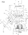
- the numeral 1 denotes a machine for making composite filters.
- the machine 1 comprises a combining unit 2 for combining groups 3 of filter sticks which have different filtering properties and whose length is variable from a minimum value to a maximum value;
- the groups 3 of filter sticks are aligned with each other along a main axis of extension 3a and advance along a first feed path P1 at a first spacing.
- the machine 1 comprises a first conveyor 4 which rotates about its axis 4a parallel to the axis 3a of the groups 3 of filter sticks.
- the first conveyor 4 is equipped with a plurality of first carrier assemblies 5, each having at least one first hold-down seat 6 with axis 6a parallel to the axis 3a of the groups 3 of filter sticks.
- the first conveyor 4 receives the groups 3 of filter sticks from the combining unit 2.
- At least one transfer roller 17 conveys the groups 3 of filter sticks from the combining unit 2 to the first conveyor 4.
- the machine 1 comprises a second conveyor 7 which rotates about its axis 7a parallel to the axis 4a of the first conveyor 4.
- the second conveyor 7 is equipped with a plurality of second carrier assemblies 8, each having at least one second hold-down seat 9 with axis 9a substantially perpendicular to the axis 6a of the first seat 6 of the first carrier assemblies 5 of the first conveyor 4.
- the groups 3 of filter sticks advance with their main axis of extension 3a parallel to the first path P1.
- the second seats 9 of the second conveyor 7 can describe a circle whose radius varies from a minimum to a maximum with variation of the length of the groups 3 of filter sticks.
- the second seats 9 of the second conveyor 7 describe a circle whose radius varies from a minimum to a maximum when the length of the groups 3 of filter sticks increases.
- the machine 1 comprises a forming beam 10 for forming at least one continuous succession 11 of groups 3 of filter sticks aligned and in contact with each other to eventually define a respective single continuous rod of filter sticks.
- the machine 1 comprises a forming beam 10 for forming two continuous successions 11 of groups 3 of filter sticks aligned and in contact with each other to eventually define two respective individual continuous rods of filter sticks.
- the forming beam 10 extends along a forming line 12 substantially parallel to the first feed path P1.
- the machine 1 comprises a transfer unit 13 interposed between the first and the second rotating conveyor 4 and 7.
- the transfer unit 13 comprises a first, cylindrical splined roller 14 with axis 14a parallel to the first and the second rotating conveyor 4, 7 and a second, tapered splined roller 15 with axis 15a inclined to the first, cylindrical roller 14 and tangent thereto.
- first, cylindrical splined roller 14 is tangent to the first rotating conveyor 4 and the second, tapered splined roller 15 is tangent to the second rotating conveyor 7.
- the first, cylindrical splined roller 14 and the second, tapered splined roller 15 are coupled to a respective shaft 19, 29.
- the transfer unit 13 comprises at least one drive shaft 27, which rotates about its axis of rotation 27a, for moving the first and second splined rollers 14 and 15.
- the drive shaft 27 is driven in rotation by a motor unit schematically represented as a block 34.
- the transfer unit 13 comprises adapter means 16 capable of adapting the transfer unit 13 to variations of the circle described by the second seats 9 of the second conveyor 7, that is to say, to variations of the length of the groups 3 of filter sticks.
- the adapter means 16 allow the axis 15a of the second, tapered roller 15 to be kept fixed while varying the position of the axis 14a of the first, cylindrical roller 14 relative to the transfer unit 13.
- the adapter means 16 allow the axis 14a of the first, cylindrical roller 14 to be kept fixed while varying the position of the axis 15a of the second, tapered roller 15 relative to the transfer unit.
- the adapter means 16 refer preferably to the first, cylindrical roller 14 .
- the adapter means 16 comprise a supporting element 18 for supporting the first, cylindrical roller 14.
- the transfer unit 13 comprises a containment box 20 relative to which the supporting element 18 is interchangeable with variation of the length of the groups 3 of filter sticks, that is, with variation of the circle described by the second seats 9 of the second conveyor 7.
- the box 20 contains at least the first, cylindrical splined roller 14, the second, tapered splined roller 15 and the drive shaft 27.
- the supporting element 18 comprises rapid connect/disconnect means 21 allowing it to be quickly interchanged relative to the transfer unit 13.
- the supporting element 18 comprises a spacer sleeve 22 having a hole 23 in it for receiving the shaft 19 of the first, cylindrical roller 14 - or the shaft 29 of the second, tapered roller 15 in the alternative embodiment, not illustrated - the position of whose respective axis 14a must be changed relative to the transfer unit 13.
- the sleeve 22 has an outside surface 24 designed to be stably coupled to a respective receiving seat 25 formed on the box 20 of the transfer unit 13.
- the spacer sleeve 22 is made in as many different shapes as there are positions which may be adopted by the axis of rotation 14a of the shaft 19 of the respective first, cylindrical roller 14, the position of whose respective axis 14a must be changed relative to the transfer unit 13.
- the position of the hole 23 which receives the shaft 19 of the respective first roller 14 changes in such a way that, once mounted on the respective receiving seat 25, the axis of rotation 14a of the shaft 19 of the respective first roller 14 is in the correct position when the length of the groups 3 of the filter sticks varies.
- the spacer sleeve 22 is interchangeable with variation of the circle described by the second seats 9 of the second conveyor 7. With variation of the spacer sleeve 22, the position of the axis 14a of the shaft 19 of the respective first, cylindrical roller 14 varies relative to the receiving seat 25 of the box 20.
- the adapter means 16 comprise a plurality of transmission means 26 which kinematically connect the motor drive shaft 27 and the shaft 19 of the respective first, cylindrical roller 14 the position of whose respective axis 14a must be changed relative to the transfer unit 13.
- the plurality of transmission means 26 comprise at least one transmission wheel 28 whose position can be varied to adapt the transmission means 26 when the supporting element 18 is interchanged and which allows keeping the transmission means 26 mutually meshed when the position of the axis 14a of the shaft 19 of the first, cylindrical roller 14 varies.
- the transmission wheel 28 is movable when the supporting element 18 is interchanged, that is to say, the transmission wheel 28 varies the position of its axis 28a relative to the receiving seat 25 of the box 20 when the spacer sleeve 22 varies.
- the transmission means 26 comprise at least a first, a second and a third transmission wheel 30, 31, 32 which mesh with one and the other in succession.
- the first, second and third wheels 30, 31, 32 rotate about respective axes of rotation 30a, 31 a, 32a which are parallel to each other and parallel to the axis of rotation 14a of the first, cylindrical roller 14.
- the axes of rotation 30a, 31 a, 32a of the first, second and third wheels 30, 31, 32 are parallel to the axis 28a of the movable transmission wheel 28 and of the shaft 19 of the first, cylindrical roller 14.
- the first wheel 30 is keyed to the drive shaft 27 and transmits motion from the latter to the second wheel 31 and, consequently, to the third wheel 32.
- the third wheel 32 is kinematically connected to the movable transmission wheel 28 and is adaptable for every size changeover. More specifically, the third wheel 32 is meshed directly with the movable transmission wheel 28.
- first, second and third transmission wheels 30, 31, 32 maintain their position relative to the movable transmission wheel 28 when the supporting element 18 is interchanged.
- the transmission means comprise a fourth wheel 35 supported by the shaft 19 of the first, cylindrical roller 14.
- the fourth wheel 35 is meshed with the movable transmission wheel 28.
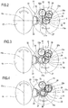
- Figures 2 to 4 illustrate the configurations adopted by the transmission means 26 and by the shaft 19 of the first, cylindrical roller 14 when the supporting element 18 is interchanged for every size changeover, that is, from groups 3 of filter sticks of maximum length ( Figure 2 ) to groups 3 of filter sticks of minimum length ( Figure 4 ).
- Figure 2 shows the configuration with the groups 3 of filter sticks of maximum length. Taking as reference the drive shaft 27 rotating about its axis of rotation 27a, the axis 14a of the shaft 19 of the first, cylindrical roller 14 is spaced at a maximum distance from the axis 27a of the drive shaft 27.
- the axis 14a of the shaft 19 of the first, cylindrical roller 14 is spaced at a minimum distance from the axis 27a of the drive shaft 27.
- the axis 14a of the shaft 19 of the first, cylindrical roller 14 is spaced at a distance from the axis 27a of the drive shaft 27 which is intermediate between the distances in the configurations shown in Figure 2 and Figure 4 .
- the axis 14a of the shaft 19 of the first, cylindrical roller 14 moves towards and away from the axis 27a of the drive shaft 27 with variation of the circle described by the second seats 9 of the second conveyor 7.
- the transmission wheel 28 can be repositioned to follow the variations in position of the axis 14a of the shaft 19 of the first, cylindrical roller 14, thus remaining meshed with the latter and with the third transmission wheel 32.
- the second, tapered roller 15 is supported by a respective shaft 29, rotating about the axis 15a.
- the second, tapered roller 15 is driven in rotation about its axis 15a by means of the drive shaft 27.
- the adapter means 16 comprise a single bevel gear pair 33 which kinematically connects the shaft 29 of the second, tapered roller 15 to the drive shaft 27.
- the first, cylindrical roller 14 and the second, tapered roller 15 are substituted for respective rollers 14, 15 which are larger in diameter.
- cylindrical roller 14 Since each size of the first, cylindrical roller 14 has an integrated spacer sleeve 22 and a respective wheel 35 which meshes with the movable transmission wheel 28, substituting the first, cylindrical roller 14 is easier than in the prior art.
Landscapes
- Cigarettes, Filters, And Manufacturing Of Filters (AREA)
- Centrifugal Separators (AREA)
- Separation By Low-Temperature Treatments (AREA)
- Electrical Discharge Machining, Electrochemical Machining, And Combined Machining (AREA)
Claims (10)
- Machine pour la fabrication de filtres composites comprenant au moins une unité de combinaison (2) pour combiner des groupes (3) de bâtonnets-filtres, les groupes (3) ayant, par rapport à leur axe (3a), une longueur étant variable d'une valeur minimum à une valeur maximum,
un premier convoyeur (4) tournant autour d'un axe (4a) parallèle à l'axe (3a) des groupes (3) de bâtonnets-filtres et équipé d'une pluralité de premiers assemblages de support (5), chacun comportant au moins un premier siège de retenue (6) avec l'axe (6a) parallèle à l'axe (3a) des groupes (3) des bâtonnets-filtres ;
un second convoyeur (7) tournant autour d'un axe (7a) parallèle au premier convoyeur (4) et équipé d'une pluralité de seconds assemblages de support (8), chacun comportant au moins un second siège de retenue (9) avec l'axe (9a) substantiellement perpendiculaire à l'axe (6a) du premier siège (6), les seconds sièges (6) pouvant décrire un cercle dont le rayon varie d'un minimum à un maximum avec une variation de la longueur des groupes (3) de bâtonnets-filtres ;
une poutre de formation (10) servant à former au moins une succession continue (11) de groupes (3) de bâtonnets-filtres en contact et alignement réciproque le long de l'axe (3a), chaque succession (11) formant une tige continue de bâtonnets-filtres ;
une unité de transfert (13) interposée entre les premier et second convoyeurs rotatifs (4, 7) ; la machine étant caractérisée en ce que l'unité de transfert (13) comprend des moyens adaptateurs (16) pouvant adapter la même unité de transfert (13) aux variations du cercle décrit par les seconds sièges (9) du second convoyeur (7). - Machine selon la revendication 1, caractérisée en ce que l'unité de transfert (13) comprend un premier rouleau cylindrique à cannelures (14) avec l'axe (14a) parallèle aux premier et au second convoyeurs rotatifs (4, 7) et un second rouleau conique à cannelures (15) avec l'axe (15a) incliné par rapport au premier rouleau cylindrique (14) et tangent à celui-ci ; le premier rouleau cylindrique à cannelures (14) et le second rouleau conique à cannelures (15) étant couplés à un arbre respectif (19, 29).
- Machine selon la revendication 2, caractérisée en ce que les moyens adaptateurs (16) conservent l'axe (15a) du second rouleau conique (15) fixe et modifient la position de l'axe (14a) du premier rouleau cylindrique (14) par rapport à l'unité de transfert (13) ou conservent l'axe (14a) du premier rouleau cylindrique (14) fixe et modifient la position de l'axe (15a) du second rouleau conique (15) par rapport à l'unité de transfert (13).
- Machine selon les revendications 2 ou 3, caractérisée en ce que les moyens adaptateurs (16) comprennent un élément de support (18) pour supporter le premier rouleau cylindrique (14) ou le second rouleau conique (15) ; l'unité de transfert (13) comprenant un boîtier de confinement (20) par rapport à laquelle l'élément de support (18) est interchangeable avec la variation du cercle décrit par les seconds sièges (9) du second convoyeur (7).
- Machine selon la revendication 4, caractérisée en ce que l'élément de support (18) comprend un manchon entretoise (22) comportant un orifice (23) en son sein pour recevoir l'arbre (19, 29) des premier rouleau cylindrique (14) ou second rouleau conique (15) respectifs ; le manchon (22) comportant une surface extérieure (24) conçue pour être stablement couplée à un siège de réception (25) respectif formé sur le boîtier (20) de l'unité de transfert (13).
- Machine selon la revendication 5, caractérisée en ce que le manchon entretoise (22) est interchangeable avec la variation du cercle décrit par les seconds sièges (9) du second convoyeur (7) ; avec la variation du manchon entretoise (22), la position de l'axe (14a, 15a) de l'arbre (19, 29) des premier rouleau cylindrique (14) ou second rouleau conique (15) respectifs variant par rapport au siège de réception (25) du boîtier (20).
- Machine selon l'une quelconque des revendications de 2 à 6, caractérisée en ce que les moyens adaptateurs (16) comprennent au moins un arbre d'entraînement motorisé (27) pour déplacer le premier et le second rouleau (14, 15) et une pluralité de moyens de transmission (26) reliant cinématiquement l'arbre d'entraînement (27) et l'arbre (19, 29) des premier rouleau cylindrique (14) ou second rouleau conique (15) respectifs.
- Machine selon la revendication 7, caractérisée en ce que les moyens de transmission (26) comprennent au moins une roue de transmission (28) tournant autour de son axe de rotation (28a) ; la roue de transmission (28) modifiant la position de son axe (28a) par rapport au siège de réception (25) du boîtier (20) avec la variation du manchon entretoise (22).
- Machine selon les revendications 7 ou 8, caractérisée en ce que l'axe (14a, 15a) de l'arbre (19, 29) du premier rouleau cylindrique (14) ou du second rouleau conique (15) respectif se rapproche ou s'éloigne de l'axe (27a) de l'arbre d'entraînement (27) avec la variation du cercle décrit par les seconds sièges (9) du second convoyeur (7).
- Machine selon l'une quelconque des revendications de 7 à 9, caractérisée en ce que le boîtier (20) contient au moins le premier rouleau cylindrique à cannelures (14), le second rouleau conique à cannelures (15) et l'arbre d'entraînement (27).
Priority Applications (1)
| Application Number | Priority Date | Filing Date | Title |
|---|---|---|---|
| PL14789392T PL3048908T3 (pl) | 2013-09-26 | 2014-09-19 | Maszyna do wytwarzania filtrów kompozytowych |
Applications Claiming Priority (2)
| Application Number | Priority Date | Filing Date | Title |
|---|---|---|---|
| IT000526A ITBO20130526A1 (it) | 2013-09-26 | 2013-09-26 | Macchina per la produzione di filtri. |
| PCT/IB2014/064664 WO2015044848A1 (fr) | 2013-09-26 | 2014-09-19 | Machine pour la fabrication de filtres composites |
Publications (2)
| Publication Number | Publication Date |
|---|---|
| EP3048908A1 EP3048908A1 (fr) | 2016-08-03 |
| EP3048908B1 true EP3048908B1 (fr) | 2017-07-26 |
Family
ID=49639946
Family Applications (1)
| Application Number | Title | Priority Date | Filing Date |
|---|---|---|---|
| EP14789392.9A Active EP3048908B1 (fr) | 2013-09-26 | 2014-09-19 | Machine pour la fabrication de filtres composites |
Country Status (4)
| Country | Link |
|---|---|
| EP (1) | EP3048908B1 (fr) |
| IT (1) | ITBO20130526A1 (fr) |
| PL (1) | PL3048908T3 (fr) |
| WO (1) | WO2015044848A1 (fr) |
Families Citing this family (2)
| Publication number | Priority date | Publication date | Assignee | Title |
|---|---|---|---|---|
| ITUA20161917A1 (it) | 2016-03-24 | 2017-09-24 | Gd Spa | Macchina e metodo per la produzione di filtri per sigarette. |
| US10375986B1 (en) | 2018-02-28 | 2019-08-13 | Altria Client Services Llc | Spacing drum and method |
Family Cites Families (3)
| Publication number | Priority date | Publication date | Assignee | Title |
|---|---|---|---|---|
| GB1522596A (en) * | 1974-10-15 | 1978-08-23 | Hauni Werke Koerber & Co Kg | Production of filter plugs |
| ITBO20050696A1 (it) * | 2005-11-16 | 2007-05-17 | Gd Spa | Macchina per la produzione di filtri composti |
| ITBO20110158A1 (it) * | 2011-03-28 | 2012-09-29 | Gd Spa | Tamburo di trasferimento o di accompagnamento per spezzoni di filtro o di sigaretta con teste operative portate da bracci radiali. |
-
2013
- 2013-09-26 IT IT000526A patent/ITBO20130526A1/it unknown
-
2014
- 2014-09-19 PL PL14789392T patent/PL3048908T3/pl unknown
- 2014-09-19 EP EP14789392.9A patent/EP3048908B1/fr active Active
- 2014-09-19 WO PCT/IB2014/064664 patent/WO2015044848A1/fr active Application Filing
Non-Patent Citations (1)
| Title |
|---|
| None * |
Also Published As
| Publication number | Publication date |
|---|---|
| PL3048908T3 (pl) | 2017-12-29 |
| EP3048908A1 (fr) | 2016-08-03 |
| WO2015044848A1 (fr) | 2015-04-02 |
| ITBO20130526A1 (it) | 2015-03-27 |
Similar Documents
| Publication | Publication Date | Title |
|---|---|---|
| EP3639681B1 (fr) | Machine d'assemblage de production de cigarettes et procédé d'assemblage associé | |
| US7281621B2 (en) | Apparatus for the transfer of rod-shaped articles | |
| EP1704788A1 (fr) | Dispositif pour la production de filtres composites | |
| EP2505086B1 (fr) | Tambour d'alimentation ou de transfert, avec têtes de fonctionnement montées sur un bras radial pour parties de filtre ou de cigarette | |
| EP2767177B1 (fr) | Procédé, mécanisme et appareil de compression momentanée de matériau de filtre | |
| EP2884860B2 (fr) | Tambour de convoyeur rotatif adapté pour être utilisé dans des machines de traitement du tabac, procédé et appareil pour transporter des éléments semblables à une tige au moyen d'un tel tambour, et machine pour la fabrication de tiges à plusieurs éléments | |
| EP2916668B1 (fr) | Machine d'assemblage de fabrication de cigarette et procédé d'assemblage associé | |
| EP3048908B1 (fr) | Machine pour la fabrication de filtres composites | |
| EP3322309B1 (fr) | Procédé et appareil de déplacement d'articles en forme de bâtons | |
| EP3790519B1 (fr) | Dispositif et procede pour traiter et appliquer des pieces en vue de la fabrication d'articles absorbants | |
| EP3549458B1 (fr) | Procédé et appareil de transport d'articles en forme de tige de l'industrie du tabac | |
| EP3723521B1 (fr) | Unité de compactage pour l'industrie du tabac | |
| CN103251127A (zh) | 用于棒形物品接收及传输的装置 | |
| EP3048907B1 (fr) | Unité d'acheminement pour acheminer des produits aux dimensions longitudinales réduites dans des machines de l'industrie du tabac | |
| ITBO960143A1 (it) | Metodo e dispositivo di rullatura per macchine mettifiltro | |
| WO2023105407A1 (fr) | Procédé et système de fabrication d'articles à segments multiples |
Legal Events
| Date | Code | Title | Description |
|---|---|---|---|
| PUAI | Public reference made under article 153(3) epc to a published international application that has entered the european phase |
Free format text: ORIGINAL CODE: 0009012 |
|
| 17P | Request for examination filed |
Effective date: 20160406 |
|
| AK | Designated contracting states |
Kind code of ref document: A1 Designated state(s): AL AT BE BG CH CY CZ DE DK EE ES FI FR GB GR HR HU IE IS IT LI LT LU LV MC MK MT NL NO PL PT RO RS SE SI SK SM TR |
|
| AX | Request for extension of the european patent |
Extension state: BA ME |
|
| DAX | Request for extension of the european patent (deleted) | ||
| GRAP | Despatch of communication of intention to grant a patent |
Free format text: ORIGINAL CODE: EPIDOSNIGR1 |
|
| INTG | Intention to grant announced |
Effective date: 20170410 |
|
| GRAS | Grant fee paid |
Free format text: ORIGINAL CODE: EPIDOSNIGR3 |
|
| GRAA | (expected) grant |
Free format text: ORIGINAL CODE: 0009210 |
|
| AK | Designated contracting states |
Kind code of ref document: B1 Designated state(s): AL AT BE BG CH CY CZ DE DK EE ES FI FR GB GR HR HU IE IS IT LI LT LU LV MC MK MT NL NO PL PT RO RS SE SI SK SM TR |
|
| REG | Reference to a national code |
Ref country code: GB Ref legal event code: FG4D |
|
| REG | Reference to a national code |
Ref country code: CH Ref legal event code: EP |
|
| REG | Reference to a national code |
Ref country code: AT Ref legal event code: REF Ref document number: 911653 Country of ref document: AT Kind code of ref document: T Effective date: 20170815 |
|
| REG | Reference to a national code |
Ref country code: IE Ref legal event code: FG4D |
|
| REG | Reference to a national code |
Ref country code: DE Ref legal event code: R096 Ref document number: 602014012358 Country of ref document: DE |
|
| REG | Reference to a national code |
Ref country code: NL Ref legal event code: MP Effective date: 20170726 |
|
| REG | Reference to a national code |
Ref country code: LT Ref legal event code: MG4D |
|
| REG | Reference to a national code |
Ref country code: AT Ref legal event code: MK05 Ref document number: 911653 Country of ref document: AT Kind code of ref document: T Effective date: 20170726 |
|
| PG25 | Lapsed in a contracting state [announced via postgrant information from national office to epo] |
Ref country code: SE Free format text: LAPSE BECAUSE OF FAILURE TO SUBMIT A TRANSLATION OF THE DESCRIPTION OR TO PAY THE FEE WITHIN THE PRESCRIBED TIME-LIMIT Effective date: 20170726 Ref country code: FI Free format text: LAPSE BECAUSE OF FAILURE TO SUBMIT A TRANSLATION OF THE DESCRIPTION OR TO PAY THE FEE WITHIN THE PRESCRIBED TIME-LIMIT Effective date: 20170726 Ref country code: LT Free format text: LAPSE BECAUSE OF FAILURE TO SUBMIT A TRANSLATION OF THE DESCRIPTION OR TO PAY THE FEE WITHIN THE PRESCRIBED TIME-LIMIT Effective date: 20170726 Ref country code: AT Free format text: LAPSE BECAUSE OF FAILURE TO SUBMIT A TRANSLATION OF THE DESCRIPTION OR TO PAY THE FEE WITHIN THE PRESCRIBED TIME-LIMIT Effective date: 20170726 Ref country code: NL Free format text: LAPSE BECAUSE OF FAILURE TO SUBMIT A TRANSLATION OF THE DESCRIPTION OR TO PAY THE FEE WITHIN THE PRESCRIBED TIME-LIMIT Effective date: 20170726 Ref country code: HR Free format text: LAPSE BECAUSE OF FAILURE TO SUBMIT A TRANSLATION OF THE DESCRIPTION OR TO PAY THE FEE WITHIN THE PRESCRIBED TIME-LIMIT Effective date: 20170726 Ref country code: NO Free format text: LAPSE BECAUSE OF FAILURE TO SUBMIT A TRANSLATION OF THE DESCRIPTION OR TO PAY THE FEE WITHIN THE PRESCRIBED TIME-LIMIT Effective date: 20171026 |
|
| PG25 | Lapsed in a contracting state [announced via postgrant information from national office to epo] |
Ref country code: ES Free format text: LAPSE BECAUSE OF FAILURE TO SUBMIT A TRANSLATION OF THE DESCRIPTION OR TO PAY THE FEE WITHIN THE PRESCRIBED TIME-LIMIT Effective date: 20170726 Ref country code: GR Free format text: LAPSE BECAUSE OF FAILURE TO SUBMIT A TRANSLATION OF THE DESCRIPTION OR TO PAY THE FEE WITHIN THE PRESCRIBED TIME-LIMIT Effective date: 20171027 Ref country code: LV Free format text: LAPSE BECAUSE OF FAILURE TO SUBMIT A TRANSLATION OF THE DESCRIPTION OR TO PAY THE FEE WITHIN THE PRESCRIBED TIME-LIMIT Effective date: 20170726 Ref country code: IS Free format text: LAPSE BECAUSE OF FAILURE TO SUBMIT A TRANSLATION OF THE DESCRIPTION OR TO PAY THE FEE WITHIN THE PRESCRIBED TIME-LIMIT Effective date: 20171126 Ref country code: BG Free format text: LAPSE BECAUSE OF FAILURE TO SUBMIT A TRANSLATION OF THE DESCRIPTION OR TO PAY THE FEE WITHIN THE PRESCRIBED TIME-LIMIT Effective date: 20171026 Ref country code: RS Free format text: LAPSE BECAUSE OF FAILURE TO SUBMIT A TRANSLATION OF THE DESCRIPTION OR TO PAY THE FEE WITHIN THE PRESCRIBED TIME-LIMIT Effective date: 20170726 |
|
| PG25 | Lapsed in a contracting state [announced via postgrant information from national office to epo] |
Ref country code: RO Free format text: LAPSE BECAUSE OF FAILURE TO SUBMIT A TRANSLATION OF THE DESCRIPTION OR TO PAY THE FEE WITHIN THE PRESCRIBED TIME-LIMIT Effective date: 20170726 Ref country code: CZ Free format text: LAPSE BECAUSE OF FAILURE TO SUBMIT A TRANSLATION OF THE DESCRIPTION OR TO PAY THE FEE WITHIN THE PRESCRIBED TIME-LIMIT Effective date: 20170726 Ref country code: DK Free format text: LAPSE BECAUSE OF FAILURE TO SUBMIT A TRANSLATION OF THE DESCRIPTION OR TO PAY THE FEE WITHIN THE PRESCRIBED TIME-LIMIT Effective date: 20170726 |
|
| REG | Reference to a national code |
Ref country code: CH Ref legal event code: PL Ref country code: DE Ref legal event code: R097 Ref document number: 602014012358 Country of ref document: DE |
|
| PG25 | Lapsed in a contracting state [announced via postgrant information from national office to epo] |
Ref country code: MC Free format text: LAPSE BECAUSE OF FAILURE TO SUBMIT A TRANSLATION OF THE DESCRIPTION OR TO PAY THE FEE WITHIN THE PRESCRIBED TIME-LIMIT Effective date: 20170726 Ref country code: SK Free format text: LAPSE BECAUSE OF FAILURE TO SUBMIT A TRANSLATION OF THE DESCRIPTION OR TO PAY THE FEE WITHIN THE PRESCRIBED TIME-LIMIT Effective date: 20170726 Ref country code: EE Free format text: LAPSE BECAUSE OF FAILURE TO SUBMIT A TRANSLATION OF THE DESCRIPTION OR TO PAY THE FEE WITHIN THE PRESCRIBED TIME-LIMIT Effective date: 20170726 Ref country code: IT Free format text: LAPSE BECAUSE OF FAILURE TO SUBMIT A TRANSLATION OF THE DESCRIPTION OR TO PAY THE FEE WITHIN THE PRESCRIBED TIME-LIMIT Effective date: 20170726 Ref country code: SM Free format text: LAPSE BECAUSE OF FAILURE TO SUBMIT A TRANSLATION OF THE DESCRIPTION OR TO PAY THE FEE WITHIN THE PRESCRIBED TIME-LIMIT Effective date: 20170726 |
|
| PLBE | No opposition filed within time limit |
Free format text: ORIGINAL CODE: 0009261 |
|
| STAA | Information on the status of an ep patent application or granted ep patent |
Free format text: STATUS: NO OPPOSITION FILED WITHIN TIME LIMIT |
|
| REG | Reference to a national code |
Ref country code: IE Ref legal event code: MM4A |
|
| REG | Reference to a national code |
Ref country code: BE Ref legal event code: MM Effective date: 20170930 |
|
| PG25 | Lapsed in a contracting state [announced via postgrant information from national office to epo] |
Ref country code: LU Free format text: LAPSE BECAUSE OF NON-PAYMENT OF DUE FEES Effective date: 20170919 |
|
| REG | Reference to a national code |
Ref country code: FR Ref legal event code: ST Effective date: 20180531 |
|
| 26N | No opposition filed |
Effective date: 20180430 |
|
| PG25 | Lapsed in a contracting state [announced via postgrant information from national office to epo] |
Ref country code: IE Free format text: LAPSE BECAUSE OF NON-PAYMENT OF DUE FEES Effective date: 20170919 Ref country code: CH Free format text: LAPSE BECAUSE OF NON-PAYMENT OF DUE FEES Effective date: 20170930 Ref country code: LI Free format text: LAPSE BECAUSE OF NON-PAYMENT OF DUE FEES Effective date: 20170930 |
|
| PG25 | Lapsed in a contracting state [announced via postgrant information from national office to epo] |
Ref country code: FR Free format text: LAPSE BECAUSE OF NON-PAYMENT OF DUE FEES Effective date: 20171002 Ref country code: BE Free format text: LAPSE BECAUSE OF NON-PAYMENT OF DUE FEES Effective date: 20170930 Ref country code: SI Free format text: LAPSE BECAUSE OF FAILURE TO SUBMIT A TRANSLATION OF THE DESCRIPTION OR TO PAY THE FEE WITHIN THE PRESCRIBED TIME-LIMIT Effective date: 20170726 |
|
| PG25 | Lapsed in a contracting state [announced via postgrant information from national office to epo] |
Ref country code: MT Free format text: LAPSE BECAUSE OF NON-PAYMENT OF DUE FEES Effective date: 20170919 |
|
| GBPC | Gb: european patent ceased through non-payment of renewal fee |
Effective date: 20180919 |
|
| PG25 | Lapsed in a contracting state [announced via postgrant information from national office to epo] |
Ref country code: HU Free format text: LAPSE BECAUSE OF FAILURE TO SUBMIT A TRANSLATION OF THE DESCRIPTION OR TO PAY THE FEE WITHIN THE PRESCRIBED TIME-LIMIT; INVALID AB INITIO Effective date: 20140919 |
|
| PG25 | Lapsed in a contracting state [announced via postgrant information from national office to epo] |
Ref country code: GB Free format text: LAPSE BECAUSE OF NON-PAYMENT OF DUE FEES Effective date: 20180919 Ref country code: CY Free format text: LAPSE BECAUSE OF FAILURE TO SUBMIT A TRANSLATION OF THE DESCRIPTION OR TO PAY THE FEE WITHIN THE PRESCRIBED TIME-LIMIT Effective date: 20170726 |
|
| PG25 | Lapsed in a contracting state [announced via postgrant information from national office to epo] |
Ref country code: MK Free format text: LAPSE BECAUSE OF FAILURE TO SUBMIT A TRANSLATION OF THE DESCRIPTION OR TO PAY THE FEE WITHIN THE PRESCRIBED TIME-LIMIT Effective date: 20170726 |
|
| PG25 | Lapsed in a contracting state [announced via postgrant information from national office to epo] |
Ref country code: TR Free format text: LAPSE BECAUSE OF FAILURE TO SUBMIT A TRANSLATION OF THE DESCRIPTION OR TO PAY THE FEE WITHIN THE PRESCRIBED TIME-LIMIT Effective date: 20170726 |
|
| PG25 | Lapsed in a contracting state [announced via postgrant information from national office to epo] |
Ref country code: PT Free format text: LAPSE BECAUSE OF FAILURE TO SUBMIT A TRANSLATION OF THE DESCRIPTION OR TO PAY THE FEE WITHIN THE PRESCRIBED TIME-LIMIT Effective date: 20170726 |
|
| PG25 | Lapsed in a contracting state [announced via postgrant information from national office to epo] |
Ref country code: AL Free format text: LAPSE BECAUSE OF FAILURE TO SUBMIT A TRANSLATION OF THE DESCRIPTION OR TO PAY THE FEE WITHIN THE PRESCRIBED TIME-LIMIT Effective date: 20170726 |
|
| P01 | Opt-out of the competence of the unified patent court (upc) registered |
Effective date: 20230526 |
|
| PGFP | Annual fee paid to national office [announced via postgrant information from national office to epo] |
Ref country code: PL Payment date: 20230905 Year of fee payment: 10 Ref country code: DE Payment date: 20230927 Year of fee payment: 10 |