EP3048847B1 - Procédure de demande de programmation améliorée - Google Patents
Procédure de demande de programmation améliorée Download PDFInfo
- Publication number
- EP3048847B1 EP3048847B1 EP15152520.1A EP15152520A EP3048847B1 EP 3048847 B1 EP3048847 B1 EP 3048847B1 EP 15152520 A EP15152520 A EP 15152520A EP 3048847 B1 EP3048847 B1 EP 3048847B1
- Authority
- EP
- European Patent Office
- Prior art keywords
- scheduling request
- user equipment
- transmission
- triggering
- delay
- Prior art date
- Legal status (The legal status is an assumption and is not a legal conclusion. Google has not performed a legal analysis and makes no representation as to the accuracy of the status listed.)
- Active
Links
Images


Classifications
-
- H—ELECTRICITY
- H04—ELECTRIC COMMUNICATION TECHNIQUE
- H04W—WIRELESS COMMUNICATION NETWORKS
- H04W52/00—Power management, e.g. TPC [Transmission Power Control], power saving or power classes
- H04W52/02—Power saving arrangements
- H04W52/0203—Power saving arrangements in the radio access network or backbone network of wireless communication networks
- H04W52/0206—Power saving arrangements in the radio access network or backbone network of wireless communication networks in access points, e.g. base stations
-
- H—ELECTRICITY
- H04—ELECTRIC COMMUNICATION TECHNIQUE
- H04W—WIRELESS COMMUNICATION NETWORKS
- H04W28/00—Network traffic management; Network resource management
- H04W28/02—Traffic management, e.g. flow control or congestion control
- H04W28/0278—Traffic management, e.g. flow control or congestion control using buffer status reports
-
- H—ELECTRICITY
- H04—ELECTRIC COMMUNICATION TECHNIQUE
- H04W—WIRELESS COMMUNICATION NETWORKS
- H04W52/00—Power management, e.g. TPC [Transmission Power Control], power saving or power classes
- H04W52/02—Power saving arrangements
- H04W52/0209—Power saving arrangements in terminal devices
- H04W52/0251—Power saving arrangements in terminal devices using monitoring of local events, e.g. events related to user activity
-
- H—ELECTRICITY
- H04—ELECTRIC COMMUNICATION TECHNIQUE
- H04W—WIRELESS COMMUNICATION NETWORKS
- H04W72/00—Local resource management
- H04W72/20—Control channels or signalling for resource management
- H04W72/21—Control channels or signalling for resource management in the uplink direction of a wireless link, i.e. towards the network
-
- H—ELECTRICITY
- H04—ELECTRIC COMMUNICATION TECHNIQUE
- H04W—WIRELESS COMMUNICATION NETWORKS
- H04W76/00—Connection management
- H04W76/20—Manipulation of established connections
- H04W76/28—Discontinuous transmission [DTX]; Discontinuous reception [DRX]
-
- H—ELECTRICITY
- H04—ELECTRIC COMMUNICATION TECHNIQUE
- H04W—WIRELESS COMMUNICATION NETWORKS
- H04W88/00—Devices specially adapted for wireless communication networks, e.g. terminals, base stations or access point devices
- H04W88/02—Terminal devices
-
- H—ELECTRICITY
- H04—ELECTRIC COMMUNICATION TECHNIQUE
- H04W—WIRELESS COMMUNICATION NETWORKS
- H04W88/00—Devices specially adapted for wireless communication networks, e.g. terminals, base stations or access point devices
- H04W88/08—Access point devices
-
- Y—GENERAL TAGGING OF NEW TECHNOLOGICAL DEVELOPMENTS; GENERAL TAGGING OF CROSS-SECTIONAL TECHNOLOGIES SPANNING OVER SEVERAL SECTIONS OF THE IPC; TECHNICAL SUBJECTS COVERED BY FORMER USPC CROSS-REFERENCE ART COLLECTIONS [XRACs] AND DIGESTS
- Y02—TECHNOLOGIES OR APPLICATIONS FOR MITIGATION OR ADAPTATION AGAINST CLIMATE CHANGE
- Y02D—CLIMATE CHANGE MITIGATION TECHNOLOGIES IN INFORMATION AND COMMUNICATION TECHNOLOGIES [ICT], I.E. INFORMATION AND COMMUNICATION TECHNOLOGIES AIMING AT THE REDUCTION OF THEIR OWN ENERGY USE
- Y02D30/00—Reducing energy consumption in communication networks
- Y02D30/70—Reducing energy consumption in communication networks in wireless communication networks
Definitions
- the present disclosure relates to methods for requesting uplink resources by a user equipment in a communication system.
- the present disclosure is also providing the user equipment for participating in the methods described herein.
- LTE Long Term Evolution
- High-Speed Downlink Packet Access HSDPA
- HSUPA High Speed Uplink Packet Access
- LTE Long Term Evolution
- LTE Long-Term Evolution
- UTRA Evolved UMTS Terrestrial Radio Access
- UTRAN UMTS Terrestrial Radio Access Network
- LTE Rel. 8 The LTE system represents efficient packet-based radio access and radio access networks that provide full IP-based functionalities with low latency and low cost.
- scalable multiple transmission bandwidths are specified such as 1.4, 3.0, 5.0, 10.0, 15.0, and 20.0 MHz, in order to achieve flexible system deployment using a given spectrum.
- Orthogonal Frequency Division Multiplexing OFDM
- OFDM Orthogonal Frequency Division Multiplexing
- SC-FDMA Single-carrier frequency division multiple access
- UE user equipment
- MIMO multiple-input multiple-output
- the E-UTRAN consists of an eNodeB, providing the E-UTRA user plane (PDCP/RLC/MAC/PHY) and control plane (RRC) protocol terminations towards the user equipment (UE).
- the eNodeB hosts the Physical (PHY), Medium Access Control (MAC), Radio Link Control (RLC) and Packet Data Control Protocol (PDCP) layers that include the functionality of user-plane header-compression and encryption. It also offers Radio Resource Control (RRC) functionality corresponding to the control plane.
- RRC Radio Resource Control
- the eNodeBs are interconnected with each other by means of the X2 interface.
- the eNodeBs are also connected by means of the S1 interface to the EPC (Evolved Packet Core), more specifically to the MME (Mobility Management Entity) by means of the S1-MME and to the Serving Gateway (SGW) by means of the S1-U.
- EPC Evolved Packet Core
- MME Mobility Management Entity
- SGW Serving Gateway
- the S1 interface supports a many-to-many relation between MMEs/Serving Gateways and eNodeBs.
- the SGW routes and forwards user data packets, while also acting as the mobility anchor for the user plane during inter-eNodeB handovers and as the anchor for mobility between LTE and other 3GPP technologies (terminating S4 interface and relaying the traffic between 2G/3G systems and PDN GW).
- the SGW terminates the downlink data path and triggers paging when downlink data arrives for the user equipment. It manages and stores user equipment contexts, e.g. parameters of the IP bearer service, network internal routing information. It also performs replication of the user traffic in case of lawful interception.
- user equipment contexts e.g. parameters of the IP bearer service, network internal routing information. It also performs replication of the user traffic in case of lawful interception.
- the MME is the key control-node for the LTE access-network. It is responsible for idle mode user equipment tracking and paging procedure including retransmissions. It is involved in the bearer activation/deactivation process and is also responsible for choosing the SGW for a user equipment at the initial attach and at time of intra-LTE handover involving Core Network (CN) node relocation. It is responsible for authenticating the user (by interacting with the HSS).
- NAS Non-Access Stratum
- the Non-Access Stratum (NAS) signaling terminates at the MME and it is also responsible for generation and allocation of temporary identities to user equipments. It checks the authorization of the user equipment to camp on the service provider's Public Land Mobile Network (PLMN) and enforces user equipment roaming restrictions.
- PLMN Public Land Mobile Network
- the MME is the termination point in the network for ciphering/integrity protection for NAS signaling and handles the security key management. Lawful interception of signaling is also supported by the MME.
- the MME also provides the control plane function for mobility between LTE and 2G/3G access networks with the S3 interface terminating at the MME from the SGSN.
- the MME also terminates the S6a interface towards the home HSS for roaming user equipments.
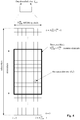
- the downlink component carrier of a 3GPP LTE system is subdivided in the time-frequency domain in so-called subframes.
- each subframe is divided into two downlink slots as shown in Fig. 3 , wherein the first downlink slot comprises the control channel region (PDCCH region) within the first OFDM symbols.
- Each subframe consists of a give number of OFDM symbols in the time domain (12 or 14 OFDM symbols in 3GPP LTE (Release 8)), wherein each OFDM symbol spans over the entire bandwidth of the component carrier.
- the OFDM symbols thus each consists of a number of modulation symbols transmitted on respective N RB DL ⁇ N sc RB subcarriers as also shown in Fig. 4 .
- a physical resource block is defined as N symb DL consecutive OFDM symbols in the time domain (e.g. 7 OFDM symbols) and N sc RB consecutive subcarriers in the frequency domain as exemplified in Fig. 4 (e.g. 12 subcarriers for a component carrier).
- a physical resource block thus consists of N symb DL ⁇ N sc RB resource elements, corresponding to one slot in the time domain and 180 kHz in the frequency domain (for further details on the downlink resource grid, see for example 3GPP TS 36.211, "Evolved Universal Terrestrial Radio Access (E-UTRA); Physical Channels and Modulation (Release 8)", section 6.2, available at http://www.3gpp.org and incorporated herein by reference).
- One subframe consists of two slots, so that there are 14 OFDM symbols in a subframe when a so-called "normal” CP (cyclic prefix) is used, and 12 OFDM symbols in a subframe when a so-called “extended” CP is used.
- a "resource block pair” or equivalent "RB pair” or "PRB pair”.
- component carrier refers to a combination of several resource blocks in the frequency domain.
- cell refers to a combination of downlink and optionally uplink resources.
- the linking between the carrier frequency of the downlink resources and the carrier frequency of the uplink resources is indicated in the system information transmitted on the downlink resources.
- the frequency spectrum for IMT-Advanced was decided at the World Radio communication Conference 2007 (WRC-07). Although the overall frequency spectrum for IMT-Advanced was decided, the actual available frequency bandwidth is different according to each region or country. Following the decision on the available frequency spectrum outline, however, standardization of a radio interface started in the 3rd Generation Partnership Project (3GPP). At the 3GPP TSG RAN #39 meeting, the Study Item description on "Further Advancements for E-UTRA (LTE-Advanced)" was approved. The study item covers technology components to be considered for the evolution of E-UTRA, e.g. to fulfill the requirements on IMT-Advanced.
- 3GPP 3rd Generation Partnership Project
- the bandwidth that the LTE-Advanced system is able to support is 100 MHz, while an LTE system can only support 20 MHz.
- the lack of radio spectrum has become a bottleneck of the development of wireless networks, and as a result it is difficult to find a spectrum band which is wide enough for the LTE-Advanced system. Consequently, it is urgent to find a way to gain a wider radio spectrum band, wherein a possible answer is the carrier aggregation functionality.
- carrier aggregation two or more component carriers are aggregated in order to support wider transmission bandwidths up to 100MHz.
- Several cells in the LTE system are aggregated into one wider channel in the LTE-Advanced system which is wide enough for 100 MHz even though these cells in LTE may be in different frequency bands.
- All component carriers can be configured to be LTE Rel. 8/9 compatible, at least when the bandwidth of a component carrier do not exceed the supported bandwidth of a LTE Rel. 8/9 cell. Not all component carriers aggregated by a user equipment may necessarily be Rel. 8/9 compatible. Existing mechanism (e.g. barring) may be used to avoid Rel-8/9 user equipments to camp on a component carrier.
- a user equipment may simultaneously receive or transmit one or multiple component carriers (corresponding to multiple serving cells) depending on its capabilities.
- a LTE-A Rel. 10 user equipment with reception and/or transmission capabilities for carrier aggregation can simultaneously receive and/or transmit on multiple serving cells, whereas an LTE Rel. 8/9 user equipment can receive and transmit on a single serving cell only, provided that the structure of the component carrier follows the Rel. 8/9 specifications.
- Carrier aggregation is supported for both contiguous and non-contiguous component carriers with each component carrier limited to a maximum of 110 Resource Blocks in the frequency domain using the 3GPP LTE (Release 8/9) numerology.
- a 3GPP LTE-A (Release 10) compatible user equipment to aggregate a different number of component carriers originating from the same eNodeB (base station) and of possibly different bandwidths in the uplink and the downlink.
- the number of downlink component carriers that can be configured depends on the downlink aggregation capability of the UE.
- the number of uplink component carriers that can be configured depends on the uplink aggregation capability of the UE. It may currently not be possible to configure a mobile terminal with more uplink component carriers than downlink component carriers.
- the number of component carriers and the bandwidth of each component carrier in uplink and downlink is the same.
- Component carriers originating from the same eNodeB need not provide the same coverage.
- the spacing between centre frequencies of contiguously aggregated component carriers shall be a multiple of 300 kHz. This is in order to be compatible with the 100 kHz frequency raster of 3GPP LTE (Release 8/9) and at the same time preserve orthogonality of the subcarriers with 15 kHz spacing. Depending on the aggregation scenario, the n ⁇ 300 kHz spacing can be facilitated by insertion of a low number of unused subcarriers between contiguous component carriers.
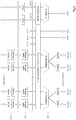
- the Layer 2 structure with activated carrier aggregation is shown in Fig. 5 and Fig. 6 for the downlink and uplink respectively.
- the mobile terminal When carrier aggregation is configured, the mobile terminal only has one RRC connection with the network.
- one cell At RRC connection establishment/re-establishment, one cell provides the security input (one ECGI, one PCI and one ARFCN) and the non-access stratum mobility information (e.g. TAI) similarly as in LTE Rel. 8/9.
- the component carrier corresponding to that cell is referred to as the downlink Primary Cell (PCell).
- PCell Downlink Primary Cell
- DL PCell downlink PCell
- UL PCell uplink PCell
- SCells Secondary Cells
- carriers of the SCell being the Downlink Secondary Component Carrier (DL SCC) and Uplink Secondary Component Carrier (UL SCC).
- RRC The configuration and reconfiguration, as well addition and removal, as of component carriers can be performed by RRC. Activation and deactivation is done via MAC control elements. At intra-LTE handover, RRC can also add, remove, or reconfigure SCells for usage in the target cell. When adding a new SCell, dedicated RRC signaling is used for sending the system information of the SCell, the information being necessary for transmission / reception (similarly as in Rel-8/9 for handover).
- a user equipment When a user equipment is configured with carrier aggregation there is at least one pair of uplink and downlink component carriers that is always active.
- the downlink component carrier of that pair might be also referred to as 'DL anchor carrier'. Same applies also for the uplink.
- a user equipment When carrier aggregation is configured, a user equipment may be scheduled on multiple component carriers simultaneously but at most one random access procedure shall be ongoing at any time.
- Cross-carrier scheduling allows the PDCCH of a component carrier to schedule resources on another component carrier.
- a component carrier identification field is introduced in the respective DCI formats, called CIF.
- a linking, established by RRC signaling, between uplink and downlink component carriers allows identifying the uplink component carrier for which the grant applies when there is no-cross-carrier scheduling.
- the linkage of downlink component carriers to uplink component carrier does not necessarily need to be one to one. In other words, more than one downlink component carrier can link to the same uplink component carrier. At the same time, a downlink component carrier can only link to one uplink component carrier.
- the basic physical resource used for data transmission consists of a frequency resource of size BW grant during one time interval, e.g. a sub-frame of 0.5 ms, onto which coded information bits are mapped.
- a sub-frame also referred to as transmission time interval (TTI)
- TTI transmission time interval
- the uplink scheme allows for both scheduled access, i.e. controlled by eNB, and contention-based access.
- the UE In case of scheduled access, the UE is allocated a certain frequency resource for a certain time (i.e. a time/frequency resource) for uplink data transmission. However, some time/frequency resources can be allocated for contention-based access. Within these time/frequency resources, UEs can transmit without first being scheduled.
- One scenario where UE is making a contention-based access is for example the random access, i.e. when UE is performing initial access to a cell or for requesting uplink resources.
- For the scheduled access Node B scheduler assigns a user a unique frequency/time resource for uplink data transmission. More specifically the scheduler determines
- the allocation information is signaled to the UE via a scheduling grant, sent on the L1/L2 control channel.
- a scheduling grant message contains information which part of the frequency band the UE is allowed to use, the validity period of the grant, and the transport format the UE has to use for the upcoming uplink transmission.
- the shortest validity period is one sub-frame. Additional information may also be included in the grant message, depending on the selected scheme.
- Only "per UE" grants are used to grant the right to transmit on the UL-SCH (i.e. there are no "per UE per RB” grants). Therefore the UE needs to distribute the allocated resources among the radio bearers according to some rules. Unlike in HSUPA, there is no UE based transport format selection.
- the eNB decides the transport format based on some information, e.g. reported scheduling information and QoS info, and UE has to follow the selected transport format.
- the Node B assigns the maximum uplink resource, and UE selects accordingly the actual transport format for the data transmissions.
- one essential aspect of the LTE scheduling scheme is to provide mechanisms with which the operator can control the partitioning of its aggregated cell capacity between the radio bearers of the different QoS classes.
- the QoS class of a radio bearer is identified by the QoS profile of the corresponding SAE bearer signaled from AGW to eNB as described before.
- An operator can then allocate a certain amount of its aggregated cell capacity to the aggregated traffic associated with radio bearers of a certain QoS class.
- the main goal of employing this class-based approach is to be able to differentiate the treatment of packets depending on the QoS class they belong to.
- L1/L2 control signaling is transmitted on the downlink along with the data.
- L1/L2 control signaling is multiplexed with the downlink data in a subframe, assuming that the user allocation can change from subframe to subframe.
- user allocation might also be performed on a TTI (Transmission Time Interval) basis, where the TTI length can be a multiple of the subframes.
- TTI length may be fixed in a service area for all users, may be different for different users, or may even by dynamic for each user.
- the L1/2 control signaling needs only be transmitted once per TTI. Without loss of generality, the following assumes that a TTI is equivalent to one subframe.
- the L1/L2 control signaling is transmitted on the Physical Downlink Control Channel (PDCCH).
- PDCCH Physical Downlink Control Channel
- a PDCCH carries a message as a Downlink Control Information (DCI), which in most cases includes resource assignments and other control information for a mobile terminal or groups of UEs.
- DCI Downlink Control Information
- several PDCCHs can be transmitted in one subframe.
- Uplink scheduling grants or uplink resource assignments are also transmitted on the PDCCH.
- Release 11 introduced an EPDCCH that fulfills basically the same function as the PDCCH, i.e. conveys L1/L2 control signalling, even though the detailed transmission methods are different from the PDCCH. Further details can be found particularly in the current versions of 3GPP TS 36.211 and 36.213, incorporated herein by reference. Consequently, most items outlined in the background and the embodiments apply to PDCCH as well as EPDCCH, or other means of conveying L1/L2 control signals, unless specifically noted.
- the information sent on the L1/L2 control signaling for assigning uplink or downlink radio resources can be categorized to the following items:
- Downlink control information occurs in several formats that differ in overall size and also in the information contained in their fields.
- the different DCI formats that are currently defined for LTE are as follows and described in detail in 3GPP TS 36.212, "Multiplexing and channel coding", section 5.3.3.1 (current version v12.3.0 available at http://www.3gpp.org and incorporated herein by reference).
- the DCI formats and the particular information that is transmitted in the DCI please refer to the mentioned technical standard or to LTE - The UMTS Long Term Evolution - From Theory to Practice, Edited by Stefanie Sesia, Issam Toufik, Matthew Baker, Chapter 9.3, incorporated herein by reference.
- DRX functionality can be configured for RRC_IDLE, in which case the UE uses either the specific or default DRX value (defaultPagingCycle); the default is broadcasted in the System Information, and can have values of 32, 64, 128 and 256 radio frames. If both specific and default values are available, the shorter value of the two is chosen by the UE. The UE needs to wake up for one paging occasion per DRX cycle, the paging occasion being one subframe.
- DRX functionality can be also configured for an "RRC_CONNECTED" UE, so that it does not always need to monitor the downlink channels.
- 3GPP LTE Release 8/9
- 3GPP LTE-A Release 10
- DRX discontinuous reception
- the following parameters are available to define the DRX UE behavior; i.e. the On-Duration periods at which the mobile node is active, and the periods where the mobile node is in a DRX mode.
- the total duration that the UE is awake is called "Active time".
- the Active Time includes the on-duration of the DRX cycle, the time UE is performing continuous reception while the inactivity timer has not expired and the time UE is performing continuous reception while waiting for a downlink retransmission after one HARQ RTT.
- the UE is awake at the subframes where uplink retransmission grants can be received, i.e. every 8ms after initial uplink transmission until maximum number of retransmissions is reached.
- the minimum active time is of fixed length equal to on-duration, and the maximum is variable depending on e.g. the PDCCH activity.
- the "DRX period” is the duration of downlink subframes during which a UE can skip reception of downlink channels for battery saving purposes.
- the operation of DRX gives the mobile terminal the opportunity to deactivate the radio circuits repeatedly (according to the currently active DRX cycle) in order to save power.
- Whether the UE indeed remains in DRX (i.e. is not active) during the DRX period may be decided by the UE; for example, the UE usually performs inter-frequency measurements which cannot be conducted during the On-Duration, and thus need to be performed some other time, during the DRX opportunity of time.
- the parameterization of the DRX cycle involves a trade-off between battery saving and latency. For example, in case of a web browsing service, it is usually a waste of resources for a UE to continuously receive downlink channels while the user is reading a downloaded web page. On the one hand, a long DRX period is beneficial for lengthening the UE's battery life. On the other hand, a short DRX period is better for faster response when data transfer is resumed - for example when a user requests another web page.
- two DRX cycles - a short cycle and a long cycle - can be configured for each UE; the short DRX cycle is optional, i.e. only the long DRX cycle is used.
- the transition between the short DRX cycle, the long DRX cycle and continuous reception is controlled either by a timer or by explicit commands from the eNodeB.
- the short DRX cycle can be considered as a confirmation period in case a late packet arrives, before the UE enters the long DRX cycle. If data arrives at the eNodeB while the UE is in the short DRX cycle, the data is scheduled for transmission at the next on-duration time, and the UE then resumes continuous reception. On the other hand, if no data arrives at the eNodeB during the short DRX cycle, the UE enters the long DRX cycle, assuming that the packet activity is finished for the time being.
- the UE monitors PDCCH, reports SRS (Sounding Reference Signal) as configured and reports CQI (Channel Quality Information)/PMI (Precoding Matrix Indicator)/RI (Rank Indicator)/PTI (Precoder Type Indication) on PUCCH.
- SRS Sounding Reference Signal
- CQI Channel Quality Information
- PMI Precoding Matrix Indicator
- RI Rank Indicator
- PTI Precoder Type Indication
- type-0-triggered SRS and CQI/PMI/RI/PTI on PUCCH may not be reported. If CQI masking is set up for the UE, the reporting of CQI/PMI/RI/PTI on PUCCH is limited to On Duration.
- Available DRX values are controlled by the network and start from non-DRX up to x seconds.
- Value x may be as long as the paging DRX used in RRC_IDLE. Measurement requirements and reporting criteria can differ according to the length of the DRX interval, i.e. long DRX intervals may have more relaxed requirements (for more details see further below).
- periodic CQI reports can only be sent by the UE during "active-time”. RRC can further restrict periodic CQI reports so that they are only sent during the on-duration.
- Fig. 8 discloses an example of DRX.
- the UE checks for scheduling messages (indicated by its C-RNTI, cell radio network temporary identity, on the PDCCH) during the "on duration" period, which is the same for the long DRX cycle and the short DRX cycle.
- the UE starts an "inactivity timer” and monitors the PDCCH in every subframe while the Inactivity Timer is running. During this period, the UE can be regarded as being in a continuous reception mode.
- the UE Whenever a scheduling message is received while the Inactivity Timer is running, the UE restarts the Inactivity Timer, and when it expires the UE moves into a short DRX cycle and starts a "short DRX cycle timer".
- the short DRX cycle may also be initiated by means of a MAC Control Element. When the short DRX cycle timer expires, the UE moves into a long DRX cycle.
- a 'HARQ Round Trip Time (RTT) timer' is defined with the aim of allowing the UE to sleep during the HARQ RTT.
- RTT Round Trip Time
- the UE can assume that the next retransmission of the transport block will occur after at least 'HARQ RTT' subframes. While the HARQ RTT timer is running, the UE does not need to monitor the PDCCH. At the expiry of the HARQ RTT timer, the UE resumes reception of the PDCCH as normal.
- the usual mode of scheduling is dynamic scheduling, by means of downlink assignment messages for the allocation of downlink transmission resources and uplink grant messages for the allocation of uplink transmission resources; these are usually valid for specific single subframes. They are transmitted on the PDCCH using C-RNTI of the UE as already mentioned before. Dynamic scheduling is efficient for services types, in which the traffic is bursty and dynamic in rate, such as TCP.
- a persistent scheduling is defined, which enables radio resources to be semi-statically configured and allocated to a UE for a longer time period than one subframe, thus avoiding the need for specific downlink assignment messages or uplink grant messages over the PDCCH for each subframe.
- Persistent scheduling is useful for services such as VoIP for which the data packets are small, periodic and semi-static in size.
- the overhead of the PDCCH is significantly reduced compared to the case of dynamic scheduling.
- Buffer status reports from the UE to the eNodeB are used to assist the eNodeB in allocating uplink resources, i.e. uplink scheduling.
- uplink scheduling i.e. uplink scheduling.
- the eNB scheduler is obviously aware of the amount of data to be delivered to each UE; however, for the uplink direction, since scheduling decisions are done at the eNB and the buffer for the data is in the UE, BSRs have to be sent from the UE to the eNB in order to indicate the amount of data that needs to be transmitted over the UL-SCH.
- Buffer Status Report MAC control elements for LTE consist of either: a long BSR (with four buffer size fields corresponding to LCG IDs #0-3) or a short BSR (with one LCG ID field and one corresponding buffer size field).
- the buffer size field indicates the total amount of data available across all logical channels of a logical channel group, and is indicated in number of bytes encoded as an index of different buffer size levels (see also 3GPP TS 36.321 v 12.4.0 Chapter 6.1.3.1, incorporated herewith by reference).
- the long BSR reports the amount of data for four logical channel groups, whereas the short BSR indicates the amount of data buffered for only the highest logical channel group.
- the eNB assigns each logical channel to a logical channel group; preferably, logical channels with same/similar QoS requirements should be allocated within the same logical channel group.
- the retransmission BSR timer is started or restarted whenever an uplink grant is restarted; if no uplink grant is received before the retransmission BSR timer expires, another BSR is triggered by the UE.
- a BSR is triggered for events, such as:
- the UE If the UE has no uplink resources allocated for including a BSR in the transport block when a BSR is triggered, the UE sends a scheduling request (SR) to the eNodeB so as to be allocated with uplink resources to transmit the BSR.
- SR scheduling request
- D-SR dedicated scheduling request
- RACH random access procedure
- the UE will not trigger the transmission of the Scheduling Request for the case that a periodic BSR is to be transmitted.
- SPS semi-persistent scheduling
- VoIP Voice over IP
- the eNodeB can allocate uplink or respectively downlink resources persistently every 20ms, which could then be used for the transmission of VoIP packets.
- SPS is beneficial for services with predictable traffic behavior, i.e. constant bit rate, packet arrival time is periodic.
- the eNodeB can turn off SR triggering/transmission for certain configured logical channels, i.e. BSR triggering due to data arrival on those specific configured logical channels will not trigger an SR.
- BSR triggering due to data arrival on those specific configured logical channels
- the motivation for such kind of enhancements is that sending a Scheduling Request for those logical channels which will use the semi-persistently allocated resources (logical channels which carry VoIP packets) is of no value for eNB scheduling and hence should be avoided.
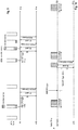
- Fig. 8 illustrates in an exemplary way the UE behaviour relating to BSR/SR when data arrives in the transmission buffer of the UE (UE Tx buffer).
- UE Tx buffer For explanatory purposes the following somewhat simplified scenario is assumed. Only one transmission buffer and one logical channel of a UE is considered. The transmission buffer is assumed to be empty at the beginning, i.e. no data is stored in the transmission buffer. Furthermore, the UE shall not have uplink resources to transmit a buffer status report to the eNodeB. However, the UE shall have semi-statically-allocated resources (e.g. allocated by means of RRC signaling) available in the PUCCH for transmitting a scheduling request (may also be referred to as dedicated scheduling request, D-SR), when necessary; i.e. performing a RACH procedure to send the scheduling request is thus not necessary which simplifies the illustration.
- semi-statically-allocated resources e.g. allocated by means of RRC signaling
- D-SR dedicated scheduling request
- the UE instead of using the allocated resources of the PUCCH for transmitting the SR, the UE might have to perform a RACH procedure to transmit the scheduling request in case no such D-SR uplink resources are available; in the present application, the expressions "scheduling request occasion” (also “scheduling request transmission occasion") are used to refer to both, i.e. to a dedicated SR and the RACH procedure.
- the UE When new data arrives in the transmission buffer of the UE at time t1, the UE has to first request uplink resources for transmission of the data since no appropriate uplink resources are momentarily available in said respect.
- a BSR is triggered in the UE, and in view of the lack of uplink resources for transmitting even the BSR, a scheduling request is triggered in the UE for transmission.
- the UE uses the (periodically)-allocated PUCCH resources (or RACH procedure not shown in Fig. 8 ) to transmit the scheduling request to the eNodeB so as to request the eNodeB to allocate uplink resources to the UE. Accordingly, the eNodeB allocates some UL-SCH resources to the UE. Depending e.g. on the current resource usage in the uplink, the eNodeB may allocate less or more uplink resources to the UE in response to the SR, and will transmit a corresponding uplink grant via the PDCCH.
- the UE may or may not transmit data in addition to the BSR, depending on the amount of allocated PUSCH resources.
- this is considered by the UE, such that the BSR indicates the amount of data in the transmission buffer after transmitting the BSR and possibly data of the transmission buffer.
- the UE will transmit over the PUSCH only the BSR or may also include some data of the UE transmission buffer.
- Fig. 8 in the first signaling exchange it is assumed that the UE can transmit all data of the transmission buffer to the eNodeB using the uplink resources assigned by the eNodeB in response to the SR.
- the BSR informs the eNodeB about basically an empty transmission buffer, such that no further uplink grant is necessary to be allocated.
- the above procedure basically repeats itself as illustrated, with the exception that the PUSCH transmission, including the BSR and the data, does not suffice to empty the transmission buffer.
- the BSR generated by the UE at the time of transmission informs the eNodeB about the remaining data in the transmission buffer.
- the eNodeB thus will allocate to the UE further uplink resources in correspondence with the remaining data in the transmission buffer.
- a further uplink grant message is transmitted by the eNodeB to the UE, which in turn can then use the newly-assigned uplink resources to transmit the remaining data and thus empty its transmission buffer.
- the triggering of a scheduling request is delayed for some predefined time.
- the number of scheduling requests can be reduced, since due to the delay, the corresponding BSR may take into account additional data arriving in the transmission buffer(s) after the initial new-data trigger until the delay expires.
- the delay feature is configured specifically for particular logical channels e.g. those which can tolerate some delay; put differently, the delay feature is thus logical channel specific. Therefore, the eNodeB can configure for each logical channel whether a delay for the triggering of the scheduling request shall be applied or not. This can be done by way of the information element LogicalChannelConfig and the corresponding optional Boolean variable logicalChannelSR-Prohibit-r12 ; see information element LogicalChannelConfig in 3GPP TS 36.331 v12.4.1 incorporated herewith by reference.
- Fig. 9 assumes a similar scenario as for Fig. 8 , and illustrates the triggering of a BSR and SR.
- the transmission buffer is assumed to be empty at the beginning, i.e. no data is stored in the transmission buffer.
- the UE shall not have sufficient uplink resources to transmit a buffer status report to the eNodeB.
- the UE shall have semi-statically-allocated resources (e.g. allocated by means of RRC signaling) available in the PUCCH for transmitting a scheduling request (may also be referred to as dedicated scheduling request, D-SR), when necessary; i.e. performing a RACH procedure to send the scheduling request is thus not necessary which simplifies the illustration.
- the one logical channel of the scenario is configured for the SR delay function, as explained above.
- the scheduling request prohibition timer is started when the (regular) BSR has been triggered, and while the scheduling request prohibition timer is running, the triggering of the scheduling request is not executed, i.e.
- the scheduling request prohibition timer expires, the scheduling request is finally triggered, and the UE can transmit the scheduling request to the eNodeB in the next scheduling request occasion (i.e. by using the periodically allocated PUCCH resources shown in Fig. 9 , or the RACH procedure not shown in Fig. 9 ).
- the eNodeB allocates UL-SCH resources to the UE, and transmits a corresponding uplink grant via the PDCCH.
- the UE may or may not transmit data in addition to the BSR, depending on the amount of allocated PUSCH resources.
- the UE can transmit all data of the transmission buffer to the eNodeB using the uplink resources assigned by the eNodeB in response to the scheduling request.
- the buffer status report informs the eNodeB about basically an empty transmission buffer such that no further uplink grant is necessary to be allocated.
- Fig. 9 additionally illustrates the case where first data arrives in the transmission buffer at time t2 and additional data arrives in the same transmission buffer at time t3.
- the arrival of new data in the empty transmission buffer at time t2 triggers the buffer status report, which however at basically the same time also would trigger the transmission of a scheduling request (since no corresponding uplink resources are available for immediately transmitting the buffer status report).
- the scheduling request trigger is delayed by use of the corresponding prohibition timer, started upon arrival of the new data in the transmission buffer (i.e. the triggering of the BSR).
- the additional data arriving at time t3 is taking into account by the user equipment when generating the BSR to be transmitted in the uplink to the eNodeB, which would not be the case without the scheduling request delay. Consequently, the transmission of a further scheduling request is avoided, and power consumption can be reduced.
- US 20120233481 A1 describes a method, comprising: determining that an apparatus has data to be sent to a receiving entity during a sleep period of a power saving cycle, the power saving cycle comprising a wake period during which a receiver is turned on and a sleep period during which the receiver is turned off; and delaying transmission of a data indication to the receiving entity by a delaying amount.
- US2013021995 A1 relates generally to techniques for managing scheduling requests (SRs) for resources for uplink transmission.
- certain aspects of the present disclosure relate to a method for wireless communication including determining a transmit opportunity for transmitting SR for uplink resources based, at least in part, on a discontinuous reception (DRX) time cycle.
- DRX discontinuous reception
- WO2011038775 A1 describes a method for delaying sending of messages from a user equipment assigned to a base station within a cell of a mobile network.
- US2015009815 A1 describes a method of uplink shaping and scheduling request (SR) prohibition in RRC Connected Mode is proposed.
- a UE applies DRX operation in a wireless network, the UE is in RRC Connection mode.
- the UE processes a data packet to be sent to the network.
- the data packet is associated with a traffic type. If the data packet belongs to a normal traffic type, then the UE transmits a scheduling request (SR) to the network. If the data packet belongs to a background traffic type, then the UE buffers the data packet and is prohibited from sending the SR to the network until a triggering condition is satisfied.
- SR scheduling request
- embodiments may be advantageously used for example in a mobile communication system such as 3GPP LTE-A (Release 10/11/12) communication systems as described in the Technical Background section above, but the embodiments are not limited to its use in this particular exemplary communication networks.
- 3GPP LTE-A Release 10/11/12
- a mobile station or mobile node or user terminal is a physical entity within a communication network.
- One node may have several functional entities.
- a functional entity refers to a software or hardware module that implements and/or offers a predetermined set of functions to other functional entities of a node or the network.
- Nodes may have one or more interfaces that attach the node to a communication facility or medium over which nodes can communicate.
- a network entity may have a logical interface attaching the functional entity to a communication facility or medium over it may communicate with other functional entities or correspondent nodes.
- radio resources as used in the set of claims and in the application is to be broadly understood as referring to physical radio resources, such as time-frequency resources.
- scheduling request transmission occasion and "scheduling request occasion” shall be understood broadly as an opportunity for the user equipment to request uplink resources from the radio base station.
- this can be in form of a dedicated scheduling request message transmitted to the radio base station via uplink radio resources on an uplink control channel.
- this could for example also be within a random access channel procedure.
- new data used in the claims and in the description is to be understood as data that arrives/is stored in the transmission buffer which was previously not there. This data (data packets) is received from a higher layer, e.g. PDCP layer, and placed into the transmission buffer.
- PDCP layer e.g. PDCP layer
- arrival used in the claims and in the description with regard to data and transmission buffers shall be understood as that data which is to be transmitted by the user equipment “enters”, or “is put into”, or “is temporarily stored in” the transmission buffer of the corresponding logical channel for transmission.
- next is used in the claims and in the description to distinguish between different scheduling request occasions, namely between one that can effectively be used for transmitting the scheduling request but may not be directly be the next one (i.e. "next possible”), and a scheduling request occasion which is directly subsequent (i.e. "next").
- delaying the triggering of the scheduling request shall cover the concept that, although a scheduling request was (would be) triggered (e.g. since the buffer status report was triggered and assuming that no uplink resource is available to transmit the BSR), the execution of the triggering is postponed (i.e. delayed) for some time.
- 3GPP standardization allows to reduce the power consumption as explained in the background section. It is important to note that there is only one timer value of logicalChannelSR-ProhibitTimer-r12 configured per UE, which essentially means that the scheduling request is delayed for all logical channels (i.e. those for which scheduling request delaying has been configured) by the same amount of time.
- the UE In general (i.e. with and without SR delay), when a user equipment is in the sleep mode, i.e. in DRX state, and a BSR/SR is triggered, the UE transmits the scheduling request to the eNodeB in the uplink, and has to wake up and transit to active time in order to monitor for and receive the corresponding uplink grant transmitted by the eNodeB on the PDCCH. This consumes power and drains the battery considerably, especially for certain types of traffic were the frequency of scheduling request transmissions is quite high.
- Fig. 10 the DRX functionality of the UE is depicted in a simplified manner merely illustrating the periodic OnDurations of the DRX cycle; for sake of clarity, there is no distinction made between long and short DRX cycles.
- a BSR/SR is triggered due to the arrival of new data in a transmission buffer of the user equipment.
- the transmission buffer and corresponding data are associated with a logical channel for which the scheduling request delay functionality is configured by the eNodeB.
- the scheduling request is triggered and is transmitted in the next scheduling request transmission occasion, and the UE transits to active time allowing the UE to receive the corresponding uplink grant from the eNodeB. Since the SR triggering according to the arrival of new data can be at any time and the SR delay is fixed, the corresponding transmission of the scheduling request and thus the transition to active time depends on the time t1 at which the BSR/SR is triggered. Correspondingly, as depicted in Fig. 10 , the transition to active time in the user equipment is not synchronized with the active times/OnDuration periods of the DRX functionality running at the same time in the user equipment.
- the UE would have to transit to active time even though shortly afterwards the UE would be in active time anyway during the periodic OnDuration. This is an unnecessary waste of power.
- a fixed delay is implemented according to the new scheduling request trigger delay function, the same applies to previously standardized versions of the scheduling request triggering where no delays are implemented.
- the following exemplary embodiments are conceived by the inventors to mitigate the problems explained above and to provide an improved scheduling request procedure to reduce the power consumption in the user equipment.
- a user equipment is provided with transmission buffer memory for each configured logical channel which can be used for temporarily storing uplink data until it is successfully transmitted over the radio link to the radio base station. It is further assumed that the UE has no resources available to transmit the data or a buffer status report to the radio base station, thus making it necessary to request uplink resources by use of a scheduling request.
- scheduling requests may be either transmitted via periodic resources of the PUCCH allocated by the radio base station, or, in case no such periodic resources are available, by using a random access channel, RACH, procedure.
- RACH random access channel
- the triggering of the scheduling request is in response to the triggering of the buffer status report which in turn can be triggered by the arrival of new data in a transmission buffer of a logical channel of the user equipment.
- the triggering of the buffer status report can be similar or exactly the same as defined for the current 3GPP standardization particularly in 3GPP TS 36.321 (current version 12.4.0) subclause 5.4.5, e.g. for "Regular BSR".
- One of the main ideas of the exemplary embodiments is to flexibly delay the scheduling request so as to reduce power consumption in the user equipment compared to the standard triggering procedure of the prior art.
- the delay of the scheduling request according to the exemplary embodiments shall be flexible.
- the delay of the scheduling request shall be coordinated with the DRX functionality running at the user equipment, such that additional transitions to active time just in connection with the triggered scheduling request are avoided. Instead, those periods of active time where the user equipment is active for other reasons (than in connection with the triggered scheduling request) shall be exploited, such that the UE is already in active time and can thus monitor for the uplink grant which is transmitted by the radio base station in response to the scheduling request.
- the delay of the scheduling request can be achieved by either delaying the actual triggering of the scheduling request (which of course also delays the corresponding transmission of the scheduling request); or by delaying the transmission of the scheduling request (but not the triggering of same which can be executed immediately). These two alternatives will be explained separately in the following.
- the delay of the triggering of the scheduling request will be explained according to one exemplary embodiment.
- the arrival of a new data in a transmission buffer of the user equipment associated with a logical channel triggers a buffer status report, which in turn - in the absence of corresponding uplink resources to transmit the buffer status report - triggers a scheduling request.
- the triggering of the scheduling request shall be delayed in a flexible manner and shall be synchronized with the DRX functionality of the user equipment.
- the triggering of the scheduling request happens due to the triggered buffer status report, the triggering is actually not immediately executed, but the execution of the triggering of the scheduling request is delayed.
- the triggering of the buffer status report can be seen as a first condition to trigger the scheduling request, whereas an additional second condition must be fulfilled - namely the end of the delay must be reached - so as to actually trigger the scheduling request.
- the flexible delay of the triggering of the scheduling request is such that the scheduling request is triggered in one of the subframes of the periodic OnDuration period of the DRX cycle of the DRX function running at the user equipment.
- the scheduling request transmission occasions are usually configured in such a way that at least one of the scheduling request transmission occasions is during the OnDuration period of the DRX cycle.
- the triggering of the scheduling request may be delayed until the first subframe of an OnDuration period of the DRX cycle. Therefore, by appropriately delaying the trigger of the scheduling request to be before the scheduling request transmission occasion of the OnDuration period, the transmission of the scheduling request can be performed during said next OnDuration period in which the user equipment is already in active time and allows the user equipment to monitor the PDCCH for corresponding uplink grants allocated by the radio base station in response to the scheduling request. Consequently, an additional transition to active time just in connection with the triggered scheduling request is avoided, and power consumption can be reduced.
- Fig. 11 illustrates such a flexible delay of the triggering of the scheduling request in a similar manner as Fig. 10 illustrating the fixed delay of the scheduling request suggested in the prior art.
- the BSR/SR trigger is depicted to take place at time t1, meaning that at said particular point in time the arrival of new data in a transmission buffer triggers the buffer status report and in turn the scheduling request.
- a flexible delay of the trigger of the scheduling request is implemented such that scheduling request trigger is delayed to take place at the beginning of the OnDuration period, as depicted in Fig. 11 . At the beginning of every OnDuration period, the UE transitions to active time.
- the scheduling request is triggered, and the corresponding scheduling request transmission occasion during the OnDuration period is used for transmitting the triggered scheduling request.
- the user equipment is already in active time, due to being in the OnDuration period of the DRX cycle, and thus can easily monitor the PDCCH for the corresponding uplink grant from the radio base station allocating resources for the buffer status report.
- One implementation of this exemplary embodiment uses a timer to ensure that the trigger is delayed, e.g. a starting request trigger prohibition timer, which is started when the BSR is triggered, and where the scheduling request may not be triggered while the scheduling request trigger prohibition timer is running.
- This starting request prohibition timer is started with an appropriate value such that the triggering of the scheduling request is delayed until one of the subframes - e.g. the first subframe - of the OnDuration period of the DRX cycle.
- the starting value of that timer can be calculated by the user equipment, which knows in advance when the OnDuration periods occur (i.e.
- the subframes at which the UE is in the OnDuration period of its DRX cycle are deterministic and can be simply calculated based on the corresponding formula (see TS 36.321 v12.4.0 subclause 5.7).
- the timer value with which the scheduling request trigger prohibition timer is started is calculated to be the amount of time between the one of the subframes of the OnDuration period (e.g. the first subframe) of the DRX cycle and the subframe where the timer is started.
- the scheduling request can be triggered and transmitted in the next occasion.
- the logicalChannelSR-ProhibitTimer introduced for the fixed delay can be reused, by applying a flexible timer value (calculated by the user equipment based on the next OnDuration period and the current time) instead of a fixed timer value preconfigured by the radio base station and transmitted to the user equipment.
- the currently defined variable logicalChannelSR-ProhibitTimer-r12 of the MAC-MainConfig information element (see TS 36.331 v12.4.1, MAC-MainConfig IE) with three bits has one spare value: "spare1": ENUMERATED ⁇ sf20, sf40, sf64, sf128, sf512, sf2014, sf2560, spare1 ⁇ (see TS 36.331 v12.4.1 MAC-MainConfig IE).
- This spare value i.e.
- code point can be used by the radio base station to indicate to the UE that the trigger of the scheduling request should be flexibly delayed until the next OnDuration period, while the remaining codepoints of the variable logicalChannelSR-ProhibitTimer-r12 indicate a fixed delay as currently introduced into the standardization.
- This solution is advantageous since no new RRC signalling, i.e. information element, needs to be introduced for that purpose; rather, the same mechanism already agreed for the fixed delay can be reused.
- Fig. 12 illustrates a sequence diagram for the UE behavior when using an SR trigger prohibition timer so as to implement the flexible delay of the scheduling request as explained above.
- the sequence diagram of Fig. 12 ends with the triggering of the scheduling request, but of course the BSR/SR procedure continues as explained before in detail in connection with Fig. 11 , i.e. by the user equipment receiving an uplink grant from the eNodeB, transmitting the BSR (and data) to the eNodeB using the allocated resources, and possibly receiving further uplink grants to transmit the remaining data if necessary.
- the flexible delay shall be larger than a pre-configured minimum delay so as to achieve the additional benefit that the postponing of the buffer status report allows that more data arrives in the transmission buffer, and thus less scheduling requests and uplink grants are needed, as well as that uplink transmissions transport more data in less time. It is more power efficient to transmit larger transport block sizes, rather than transmitting smaller transport block sizes.
- the total amount of delay that is used for the scheduling request trigger comprises a fixed minimum time and some variable time.
- the user equipment When using a timer to implement the flexible delay, the user equipment shall take the minimum delay time into account and thus calculate the timer value to be greater than the minimum delay time; this may result in that not the directly-next OnDuration period is used for the calculation of the timer value, but a further subsequent one.
- the trigger of the scheduling request is delayed until an OnDuration period, be it the directly-next one after the BSR is triggered (may also be the current one) or a subsequent OnDuration period.
- the flexible delay shall not be larger than a particular maximum delay so as to avoid too large a delay for the transmission of the data that triggered the BSR/SR.
- the UE might indeed need to transition to active time in connection with the triggered scheduling request just to be able to monitor and receive the corresponding uplink grant transmitted by the eNodeB in response to the scheduling request. While the additional advantage of the above explained embodiments, i.e. the reduced power consumption, is not possible in said particular case, when configuring such a maximum delay constraint it is ensured that the transmission of the data is not delayed too long.
- the minimum delay time and/or maximum delay time can be defined for example by the radio base station and can be transmitted to the UE, using appropriate signalling e.g. RRC or MAC.
- the minimum delay time can be indicated to the UE by use of the variable logicalChannelSR-ProhibitTimer-r12 of the MAC-MainConfig information element which is already defined in LTE and allows indicating seven different delay times.
- the UE since the spare codepoint of the variable logicalChannelSR-ProhibitTimer-r12 can not be used for instructing the UE to flexibly delay the triggering of the scheduling rerquest, the UE either is pre-configured to flexibly delay the trigger of the SR, or is configured separately by the eNodeB by use of another message (e.g. RRC or MAC signaling).
- another message e.g. RRC or MAC signaling
- the eNodeB could configure specific time periods during which scheduling request triggering or more in particular the execution of the scheduling request triggering is allowed. For example the eNodeB could configure the UE such, that scheduling request triggering respectively the execution of the scheduling request triggering is only allowed during the time period when OnDuration timer is running.
- the flexible delay of the scheduling request trigger is not applicable to all logical channels, but only to specific ones in a similar manner as already explained for the fixed scheduling request delay.
- some kind of data is more tolerant to delay than other, and thus the flexible delay can be logical channel specific, i.e. is configured specifically for particular logical channels, e.g. those which can tolerate some delay.
- This can be configured by the eNodeB, e.g. using the information element LogicalChannelConfig and the corresponding optional Boolean variable logicalChannelSR-Prohibit-r12 already introduced for the fixed delay of the scheduling request; see information element LogicalChannelConfig in 3GPP TS 36.331 v12.4.1.
- the eNodeB may configure the user equipment differently to flexibly delay the scheduling request triggering as explained above.
- the user equipment will only flexibly delay the scheduling request in case the buffer status reports which triggered the scheduling request, was in turn triggered upon arrival of new data in a transmission buffer associated with the specific logical channel(s). Conversely, in case new data arrives in a transmission buffer associated with a logical channel which is not configured for the flexible delay of the scheduling request, the scheduling request, triggered by the corresponding triggering of the buffer status report, will not be delayed.
- the flexible delay of the scheduling request trigger is performed until one of the subframes of the OnDuration period of the DRX cycle running at the user equipment, preferably the first subframe of an OnDuration period.
- the above-explained embodiments can be changed in that the scheduling request may be flexibly delayed to any active time of the DRX cycle running at the user equipment, i.e. not just to the OnDuration period of the active time of the DRX cycle although effectively it may be the OnDuration period as part of the active time of the DRX cycle.
- the total duration that the UE is awake is called "active time", and not only includes the OnDuration of the DRX cycle, but also other time periods, e.g.
- the UE might need to transition to active time for the BSR/SR procedure, which shall actually be avoided according to the exemplary embodiments.
- the user equipment is at least in active time for the periodic OnDuration periods, it may be further in active time for other reasons, depending on for example the PDCCH activity. In this alternative exemplary embodiment, this is exploited in that the delay of the scheduling request trigger can be postponed to any of those active time periods of the DRX functionality.
- the scheduling request shall be triggered e.g. by the triggering of a buffer status report upon arrival of new data in a transmission buffer of the UE.
- the UE postpones the triggering of the scheduling request to an Active Time. After the UE executes the triggering of the scheduling request, the UE shall transmit the scheduling request in the next scheduling request transmission occasion.
- the UE is - at the time of triggering the scheduling request - usually still in DRX sleep state, and then transitions to active time after triggering and transmitting the scheduling request so as to be able to monitor in the downlink the PDCCH for the corresponding uplink grant transmitted by the eNodeB in response to the scheduling request.
- OnDuration periods can be easily determined by the UE beforehand (i.e. they are deterministic), this is not necessarily the case for the periods where the UE is in active time, e.g. since this may depend on whether the UE receives a PDCCH during an Active Time subframe e.g. OnDuration period (see UE behaviour as explained in connection with Fig. 7 ). Consequently, in order to implement the flexible delay of the SR trigger until the UE is in Active Time, instead of using a timer as discussed before, the UE may determine for example subframe by subframe whether it will be in active time and will then execute the triggering of the scheduling request for a subframe for which it positively determines that it is already in active time for another reason.
- Fig. 13 This is schematically illustrated in Fig. 13 , where compared to Fig. 11 an active time period is present before the OnDuration period after the time instance t1.
- the delay is only performed until the beginning of the active time period.
- the UE after executing the scheduling request trigger after the delay, may then use the next scheduling request transmission occasion to transmit the scheduling request to the eNodeB.
- the UE may then easily monitor the downlink control channel for the corresponding uplink grant from the eNodeB, without the need to transition to active time merely for the purpose of receiving said uplink grant. Therefore, one transition to active time can be avoided, with the corresponding advantage of a lower power consumption.
- the delay is shorter since any active time of the DRX function can be used for actually executing the triggering of the SR.
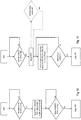
- the UE behavior for this exemplary embodiment is schematically illustrated in the sequence diagram of Fig. 14 .
- the optional implementation of the minimum delay constraint is illustrated in dashed lines; after the BSR is triggered, the UE advantageously first checks whether the minimum delay is already exceeded before continuing with the check as to whether for the next (and if necessary for further) subframes the UE is in active time or not so as to execute the SR trigger.
- the flexible delay to any active time of the UE shall not be applicable to all logical channels of a user equipment in view of the different quality of service requirements and delay tolerance of different services.
- the flexible delay of the scheduling request trigger can be limited to only particular logical channels that may be for example configured by the eNodeB.
- the exemplary embodiments suggested to flexibly delay the scheduling request trigger.
- other exemplary embodiments allow to flexibly delay the transmission of the scheduling request, while performing the triggering of the scheduling request immediately. While the effect of the delay is rather similar to the previous exemplary embodiments where the scheduling request trigger is delayed, the implementation of same may vary. Consequently, the actual effect of the delay of the transmission of the SR can be appreciated from Fig. 11 and 13 , i.e. the transmission of the SR occurs at an SR occasion during an OnDuration or other active time of the DRX cycle of the UE. The same advantages are achieved, namely that the extra transition to active time just in connection with the triggered scheduling request is avoided and thus power can be saved.
- a timer may be used according to one exemplary implementation.
- the triggered scheduling request shall not be transmitted.
- an SR transmission prohibition timer is started when the SR is triggered.
- the timer value with which the timer is started is then calculated to be such that the scheduling request is delayed until one of the subframes - e.g. the first subframe - of the OnDuration period of the DRX cycle.
- the UE knows in advance when the OnDuration periods occur, and may thus calculate the initial timer value to be the amount of time between the one of subframes of the OnDuration period (e.g. the first subframe) of the DRX cycle and the subframe where the scheduling request transmission prohibition timer is started.
- the UE upon expiry of the prohibition timer, the UE will use the next scheduling request transmission occasion to transmit the scheduling request.
- a scheduling request transmission occasion is always configured during the OnDuration period of the DRX cycle, allowing the UE to transmit the scheduling request while still in the OnDuration period.
- the logicalChannelSR-ProhibitTimer introduced for the fixed delay can be reused.
- the variable logicalChannelSR-ProhibitTimer-r12 of the MAC-MainConfig information element currently standardized can be reused by taking the spare codepoint to indicate to the UE that the scheduling request transmission shall be flexibly delayed until the next OnDuration period.
- Fig. 15 schematically illustrates the corresponding UE behavior by use of a sequence diagram.
- the buffer status report as well as the scheduling request are actually triggered immediately upon receiving new data in the corresponding transmission buffer of the user equipment.
- the transmission of the scheduling request is then postponed by use of a corresponding transmission prohibition timer, which does not allow the scheduling request to be transmitted while it is still running.
- the UE may be configured to only be able to use those scheduling request occasions which fall within the OnDuration period (s).
- a masking of the scheduling request occasions ("SR transmission masking") is performed so as to eliminate those scheduling request occasions where the UE is not in the OnDuration period of the DRX cycle. This can be simply implemented since the UE knows in advance the scheduling request occasions and the DRX OnDuration periods, both of which are configured periodically.
- a corresponding new RRC flag signalling e.g. a new flag
- a new flag can be introduced in said respect - e.g. "sr-mask" in PhysicalConfigDedicated of the radio resource control information elements - such that the eNodeB may properly instruct the UE to only use those scheduling request occasions that fall in the OnDuration period of the DRX cycle.
- a minimum and/or maximum time delay can be configured so as to achieve the additional advantages already discussed before. In particular, this may be implemented for example by calculating the timer start value accordingly to be larger than the minimum time delay.
- the scheduling request transmission masking mentioned before only those scheduling request occasions after the minimum delay shall be considered for checking whether each is in an OnDuration period or not.
- the above-explained embodiments can be changed in that the transmission of the scheduling request may be flexibly delayed to any active time of the DRX cycle running at the user equipment, i.e. not just to the OnDuration period of the active time of the DRX cycle although effectively it may be the OnDuration period as part of the active time of the DRX cycle.
- the UE delays the transmission of the scheduling request to a scheduling request transmission occasion which coincides with the UE already being in active time for a different reason (e.g. due to being in an OnDuration period of the DRX cycle).
- the UE shall determine for example for one scheduling request transmission occasion after another whether it will be in active time and will then actually perform the transmission of the scheduling request in that scheduling request transmission occasion where it positively determined to already be in active time for another reason.
- the corresponding UE behavior for this exemplary embodiment is schematically illustrated in the sequence diagram of Fig. 16 .
- the minimum delay is again optionally illustrated in dashed lines in Fig. 16 .
- the detailed UE behaviour with respect to the triggering respectively transmission of the scheduling request is depending on the DRX cycle the UE is currently using, i.e. long or short DRX cycle.
- the UE shall not delay the triggering or transmission of a scheduling request more than a configured maximum time
- the UE shall at least delay the triggering or transmission of a scheduling request by a configured minimum time.
- the eNB-configured prohibition timer value is depending on the current used DRX cycle interpreted as a minimum respectively maximum time value.
- This DRX-cycle-dependent timer value can be used in combination with the above-explained embodiments, e.g. delaying the trigger/transmission until On Duration period respectively DRX active time.
- a user terminal mobile terminal
- an eNodeB base station
- the user terminal and base station is adapted to perform the methods described herein, including corresponding entities to participate appropriately in the methods, such as receiver, transmitter, processors.
- a computing device or processor may for example be general purpose processors, digital signal processors (DSP), application specific integrated circuits (ASIC), field programmable gate arrays (FPGA) or other programmable logic devices, etc.
- DSP digital signal processors
- ASIC application specific integrated circuits
- FPGA field programmable gate arrays
- the various embodiments may also be performed or embodied by a combination of these devices.
- the various embodiments may also be implemented by means of software modules, which are executed by a processor or directly in hardware. Also a combination of software modules and a hardware implementation may be possible.
- the software modules may be stored on any kind of computer readable storage media, for example RAM, EPROM, EEPROM, flash memory, registers, hard disks, CD-ROM, DVD, etc.
Claims (13)
- Procédé pour demander des ressources de liaison montante par un équipement d'utilisateur dans un système de communication, dans lequel une fonction DRX (Discontinued Reception) s'exécute au niveau de l'équipement d'utilisateur, le procédé comprenant les étapes suivantes effectuées au niveau de l'équipement d'utilisateur :réception d'informations de configuration provenant d'une station de base radio sur la manière de retarder un déclenchement d'une demande de planification, les informations de configuration incluant un d'une pluralité de points de code où au moins un de la pluralité de points de code indique un délai flexible selon lequel le déclenchement de la demande de planification doit être retardé de sorte que la demande de planification soit déclenchée dans une des sous-trames - de préférence la première sous-trame - d'une période OnDuration d'un cycle DRX selon une fonction DRX, dans lequel les points de code restants indiquent un délai temporel fixe pour retarder le déclenchement de la demande de planification,déclenchement de la transmission de la demande de planification pour demander des ressources de liaison montante à la station de base radio sur déclenchement d'un rapport d'état de tampon dans l'équipement d'utilisateur,au cas où le point de code reçu indique le délai flexible, retardement du déclenchement de la demande de planification de sorte que la demande de planification soit déclenchée dans une des sous-trames - de préférence la première sous-trame - de la période OnDuration du cycle DRX,au cas où le point de code reçu indique le délai temporel fixe, retardement du déclenchement de la demande de planification du délai temporel fixe indiqué,transmission de la demande de planification déclenchée à la station de base radio à la prochaine occasion possible de transmission de demande de planification après que le déclenchement de la demande de planification a été retardé.
- Le procédé selon la revendication 1, dans lequel le déclenchement de la demande de planification est retardé au moins d'un délai temporel minimal préconfiguré et de préférence inférieur à un délai temporel maximal préconfiguré,
de préférence dans lequel le délai temporel minimal préconfiguré est déterminé au niveau de la station de base radio, et l'équipement d'utilisateur reçoit de la station de base radio une indication sur le délai temporel minimal préconfiguré. - Le procédé selon la revendication 1 ou 2, l'étape de retardement est effectuée au moyen d'un minuteur d'interdiction de demande de planification, dans lequel le déclenchement de la demande de planification ne peut pas être exécutée pendant que le minuteur d'interdiction de demande de planification s'exécute, préférablement en :démarrant le minuteur d'interdiction de demande de planification sur déclenchement du rapport d'état de tampon dans l'équipement d'utilisateur,dans lequel le minuteur d'interdiction de demande de planification est démarré au moyen d'une valeur de minuteur calculée par l'équipement d'utilisateur pour consister en la durée entre l'une des sous-trames - de préférence la première sous-trame - de ladite période OnDuration du cycle DRX et la sous-trame dans laquelle le minuteur est démarré,de préférence dans lequel ladite durée est supérieure à un délai temporel minimal préconfiguré de sorte que le déclenchement de la demande de planification soit retardé au moins du délai temporel minimal préconfiguré.
- Le procédé selon l'une des revendications 1 à 3, dans lequel la pluralité de canaux logiques sont configurés pour l'équipement d'utilisateur, et un rapport d'état de tampon est déclenché sur arrivée de nouvelles données dans un tampon de transmission associé à un quelconque de la pluralité de canaux logiques, dans lequel le retardement du déclenchement de la demande de planification est uniquement effectué lorsque le rapport d'état de tampon, déclenchant la demande de planification, est déclenché par une arrive de nouvelles données associées à au moins un canal logique spécifique parmi la pluralité de canaux logiques, de préférence dans lequel le canal logique spécifique est associé à des données tolérantes au délai, et
de préférence dans lequel la station de base radio détermine l'au moins un canal logique spécifique parmi la pluralité de canaux logiques, et l'équipement d'utilisateur reçoit de la station de base radio une indication sur l'au moins un canal logique spécifique. - Équipement d'utilisateur pour demander des ressources de liaison montante à une station de base radio dans un système de communication, dans lequel une fonction DRX (Discontinued Reception) s'exécute au niveau de l'équipement d'utilisateur, l'équipement d'utilisateur comprenant :un récepteur adapté pour recevoir des informations de configuration provenant d'une station de base radio sur la manière de retarder un déclenchement d'une demande de planification, les informations de configuration incluant un d'une pluralité de points de code où au moins un de la pluralité de points de code indique un délai flexible selon lequel le déclenchement de la demande de planification doit être retardé de sorte que la demande de planification soit déclenchée dans une des sous-trames - de préférence la première sous-trame - d'une période OnDuration d'un cycle DRX selon une fonction DRX, dans lequel les points de code restants indiquent un délai temporel fixe pour retarder le déclenchement de la demande de planification,un processeur adapté pour déclencher la transmission de la demande de planification pour demander des ressources de liaison montante à la station de base radio sur déclenchement d'un rapport d'état de tampon dans l'équipement d'utilisateur,au cas où le point de code reçu indique le délai flexible, le processeur étant adapté en outre pour retarder le déclenchement de la demande de planification de sorte que la demande de planification soit déclenchée dans une des sous-trames - de préférence la première sous-trame - de la période OnDuration du cycle DRX,au cas où le point de code reçu indique le délai temporel fixe, le processeur étant adapté en outre pour retarder le déclenchement de la demande de planification du délai temporel fixe indiqué,transmetteur adapté pour transmettre la demande de planification déclenchée à la station de base radio à la prochaine occasion possible de transmission de demande de planification après que le déclenchement de la demande de planification a été retardé.
- L'équipement d'utilisateur selon la revendication 5, comprenant en outre :
un minuteur d'interdiction de demande de planification, dans lequel le déclenchement de la demande de planification ne peut pas être exécutée pendant que le minuteur d'interdiction de demande de planification s'exécute, préférablement par :le processeur étant adapté en outre pour démarrer le minuteur d'interdiction de demande de planification sur déclenchement du rapport d'état de tampon,le processeur étant adapté pour calculer la durée entre l'une des sous-trames - de préférence la première sous-trame - de ladite période OnDuration du cycle DRX et la sous-trame dans laquelle le minuteur est démarré, de préférence dans lequel la durée est calculée pour être supérieure à un délai temporel minimal préconfiguré, etle processeur étant adapté en outre pour utiliser la durée calculée en tant que valeur de minuteur pour démarrer le minuteur d'interdiction de demande de planification. - Procédé pour demander des ressources de liaison montante par un équipement d'utilisateur dans un système de communication, dans lequel une fonction DRX (Discontinued Reception) s'exécute au niveau de l'équipement d'utilisateur, le procédé comprenant les étapes suivantes effectuées au niveau de l'équipement d'utilisateur :réception d'informations de configuration provenant d'une station de base radio sur la manière de retarder la transmission d'une demande de planification, les informations de configuration incluant un d'une pluralité de points de code où au moins un de la pluralité de points de code indique un délai flexible selon lequel la transmission de la demande de planification doit être retardée de sorte que la demande de planification soit transmise dans une des sous-trames - de préférence la première sous-trame - d'une période OnDuration d'un cycle DRX selon une fonction DRX, dans lequel les points de code restants indiquent un délai temporel fixe pour retarder la transmission de la demande de planification,déclenchement de la transmission de la demande de planification pour demander des ressources de liaison montante à la station de base radio sur déclenchement d'un rapport d'état de tampon dans l'équipement d'utilisateur,au cas où le point de code reçu indique le délai flexible, retardement de la transmission de la demande de planification déclenchée jusqu'à ce que l'équipement d'utilisateur soit en période active de la fonction DRX,au cas où le point de code reçu indique le délai temporel fixe, retardement de la transmission de la demande de planification du délai temporel fixe indiqué,transmission de la demande de planification déclenchée à la station de base radio après le délai et lorsque l'équipement d'utilisateur est en période active de la fonction DRX.
- Le procédé selon la revendication 7, dans lequel l'équipement d'utilisateur est en période active de la fonction DRX pour une raison autre qu'en relation avec la demande de planification déclenchée lors d'une transmission de la demande de planification déclenchée.
- Le procédé selon la revendication 7 ou 8, dans lequel l'étape de retardement de la transmission de la demande de planification comprend l'étape suivante effectuée par l'équipement d'utilisateur :détermination de la prochaine occasion possible de transmission de demande de planification pour transmettre la demande de planification déclenchée qui se trouve à un moment où l'équipement d'utilisateur est dans une période active selon la fonction DRX pour une raison autre qu'en relation avec la demande de planification déclenchée, préférablement en1) déterminant si l'équipement d'utilisateur, à la prochaine occasion de transmission de demande de planification pour transmettre la demande de planification déclenchée, est ou non dans une période active selon la fonction DRX pour une raison autre qu'en relation avec la demande de planification déclenchée.2) si l'équipement d'utilisateur est déterminé comme étant dans une période active, transmission de la demande de planification déclenchée à la station de base radio à ladite prochaine occasion de transmission de demande de planification,3) si l'équipement d'utilisateur est déterminé comme n'étant pas active, aucune activation ni transmission de la demande de planification déclenchée à ladite prochaine occasion de transmission de demande de planification, etrépétition des étapes ci-dessus 1) - 3) pour des occasions ultérieures de transmission de demande de planification jusqu'à ce que la demande de planification déclenchée soit transmise.
- Le procédé selon l'une des revendications 7 à 9, dans lequel la pluralité de canaux logiques sont configurés pour l'équipement d'utilisateur, et un rapport d'état de tampon est déclenché sur arrivée de nouvelles données dans un tampon de transmission associé à un quelconque de la pluralité de canaux logiques, dans lequel le retardement de la transmission de la demande de planification est uniquement effectué lorsque le rapport d'état de tampon, déclenchant la demande de planification, est déclenché par une arrive de nouvelles données associées à au moins un canal logique spécifique parmi la pluralité de canaux logiques, de préférence dans lequel le canal logique spécifique est associé à des données tolérantes au délai,
de préférence dans lequel la station de base radio détermine l'au moins un canal logique spécifique parmi la pluralité de canaux logiques, et l'équipement d'utilisateur reçoit de la station de base radio une indication sur l'au moins un canal logique spécifique. - Le procédé selon l'une des revendications 1 à 4 et 7 à 10, dans lequel une occasion de transmission de demande de planification est soit :une occasion de transmettre une demande de planification dans une ressource radio de liaison montante d'un canal de contrôle de liaison montante, soitune occasion de transmettre une demande de planification en effectuant une procédure de canal d'accès aléatoire entre l'équipement d'utilisateur et la station de base radio.
- Équipement d'utilisateur pour demander des ressources de liaison montante à une station de base radio dans un système de communication, dans lequel une fonction DRX (Discontinued Reception) s'exécute au niveau de l'équipement d'utilisateur, l'équipement d'utilisateur comprenant :un récepteur adapté pour recevoir des informations de configuration provenant d'une station de base radio sur la manière de retarder une transmission d'une demande de planification, les informations de configuration incluant un d'une pluralité de points de code où au moins un de la pluralité de points de code indique un délai flexible selon lequel la transmission de la demande de planification doit être retardée de sorte que la demande de planification soit transmise dans une des sous-trames - de préférence la première sous-trame - d'une période OnDuration d'un cycle DRX selon une fonction DRX, dans lequel les points de code restants indiquent un délai temporel fixe pour retarder la transmission de la demande de planification,un processeur adapté pour déclencher la transmission de la demande de planification pour demander des ressources de liaison montante à la station de base radio sur déclenchement d'un rapport d'état de tampon dans l'équipement d'utilisateur,au cas où le point de code reçu indique le délai flexible, le processeur étant adapté en outre pour retarder la transmission de la demande de planification déclenchée jusqu'à ce que l'équipement d'utilisateur soit en période active de la fonction DRX, au cas où le point de code reçu indique le délai temporel fixe, le processeur étant adapté en outre pour retarder la transmission de la demande de planification du délai temporel fixe indiqué,un transmetteur adapté pour transmettre la demande de planification déclenchée à la station de base radio après le délai et lorsque l'équipement d'utilisateur est en période active de la fonction DRX.
- L'équipement d'utilisateur selon la revendication 12, dans lequel l'équipement d'utilisateur est en période active de la fonction DRX pour une raison autre qu'en relation avec la demande de planification déclenchée lors d'une transmission de la demande de planification déclenchée.
Priority Applications (4)
| Application Number | Priority Date | Filing Date | Title |
|---|---|---|---|
| EP15152520.1A EP3048847B1 (fr) | 2015-01-26 | 2015-01-26 | Procédure de demande de programmation améliorée |
| US15/545,267 US10271347B2 (en) | 2015-01-26 | 2015-12-22 | Scheduling request procedure |
| PCT/EP2015/081049 WO2016119981A1 (fr) | 2015-01-26 | 2015-12-22 | Procédure de demande d'ordonnancement améliorée |
| JP2017535000A JP6667534B2 (ja) | 2015-01-26 | 2015-12-22 | 改良されたスケジューリング要求手順 |
Applications Claiming Priority (1)
| Application Number | Priority Date | Filing Date | Title |
|---|---|---|---|
| EP15152520.1A EP3048847B1 (fr) | 2015-01-26 | 2015-01-26 | Procédure de demande de programmation améliorée |
Publications (2)
| Publication Number | Publication Date |
|---|---|
| EP3048847A1 EP3048847A1 (fr) | 2016-07-27 |
| EP3048847B1 true EP3048847B1 (fr) | 2019-11-20 |
Family
ID=52434580
Family Applications (1)
| Application Number | Title | Priority Date | Filing Date |
|---|---|---|---|
| EP15152520.1A Active EP3048847B1 (fr) | 2015-01-26 | 2015-01-26 | Procédure de demande de programmation améliorée |
Country Status (4)
| Country | Link |
|---|---|
| US (1) | US10271347B2 (fr) |
| EP (1) | EP3048847B1 (fr) |
| JP (1) | JP6667534B2 (fr) |
| WO (1) | WO2016119981A1 (fr) |
Families Citing this family (32)
| Publication number | Priority date | Publication date | Assignee | Title |
|---|---|---|---|---|
| US10334447B2 (en) | 2015-02-27 | 2019-06-25 | Qualcomm Incorporated | Discontinuous reception procedures with enhanced component carriers |
| EP3310111B1 (fr) * | 2015-07-15 | 2021-12-08 | Huawei Technologies Co., Ltd. | Procédé et dispositif de planification fixe, et équipement utilisateur et station de base |
| CN106255184B (zh) * | 2016-07-28 | 2019-10-25 | 华为技术有限公司 | 一种数据传输方法及终端设备 |
| CN107734703B (zh) * | 2016-08-11 | 2020-11-17 | 华为技术有限公司 | 一种资源调度方法和装置 |
| WO2018030710A1 (fr) * | 2016-08-11 | 2018-02-15 | Samsung Electronics Co., Ltd. | Procédé et appareil de programmation de données de liaison montante dans un système de communications mobiles |
| WO2018031638A1 (fr) * | 2016-08-11 | 2018-02-15 | Intel IP Corporation | Demande de transmission en liaison montante destinée à plusieurs numérologies |
| WO2018062886A1 (fr) * | 2016-09-30 | 2018-04-05 | Lg Electronics Inc. | Surveillance de pdcch après configuration ou reconfiguration de drx |
| EP3527024B1 (fr) * | 2016-10-17 | 2022-03-30 | Qualcomm Incorporated | Transmissions semi-autonomes |
| JP6900475B2 (ja) * | 2016-11-04 | 2021-07-07 | テレフオンアクチーボラゲット エルエム エリクソン(パブル) | キャリアアグリゲーションのアクティブ化に関連する遅延へのsrs切替の影響の制御 |
| US10779312B2 (en) * | 2016-11-11 | 2020-09-15 | Qualcomm Incorporated | Discontinuous reception and scheduling techniques in wireless communication systems using multiple transmission time intervals |
| CA3061958C (fr) * | 2017-05-04 | 2021-03-30 | Ofinno, Llc | Demande de planification dans un dispositif sans fil et reseau sans fil |
| US10524294B2 (en) | 2017-05-04 | 2019-12-31 | Ofinno, Llc | Scheduling request transmission |
| US10568128B2 (en) | 2017-06-14 | 2020-02-18 | Qualcomm Incorporated | Techniques and apparatuses for scheduling request acknowledgement |
| EP3639601A1 (fr) * | 2017-06-15 | 2020-04-22 | Convida Wireless, LLC | Demandes de planification, rapports d'état et hiérarchisation de canal logique |
| US10772151B2 (en) | 2018-01-05 | 2020-09-08 | Ofinno, Llc | Beam management in discontinuous reception |
| KR102543090B1 (ko) * | 2018-01-08 | 2023-06-14 | 삼성전자주식회사 | 무선 통신 시스템에서 자원을 할당하기 위한 장치 및 방법 |
| GB2571073B (en) * | 2018-02-09 | 2021-01-13 | Tcl Communication Ltd | Control information transmission |
| US11284423B2 (en) * | 2018-02-10 | 2022-03-22 | Telefonaktiebolaget Lm Ericsson (Publ) | Methods, user equipment and base station for processing scheduling request |
| US10764962B2 (en) * | 2018-02-15 | 2020-09-01 | Apple Inc. | Methods to handle scheduling requests for ultra-reliable low latency communication (URLLC) in new radio (NR) systems |
| US11013056B2 (en) * | 2018-04-13 | 2021-05-18 | Qualcomm Incorporated | Dynamic prioritization of uplink traffic |
| KR102632780B1 (ko) * | 2018-05-10 | 2024-02-02 | 삼성전자주식회사 | 무선 통신 시스템에서 서비스를 제공하기 위한 장치 및 방법 |
| CN111869314B (zh) * | 2018-10-19 | 2022-01-11 | Oppo广东移动通信有限公司 | 无线通信方法、终端设备、芯片和介质 |
| CN111491393B (zh) * | 2019-01-25 | 2022-01-14 | 华为技术有限公司 | 随机接入方法、终端设备以及网络设备 |
| US11503620B2 (en) * | 2019-11-11 | 2022-11-15 | Qualcomm Incorporated | Techniques for identifying a scheduling request occasion for connected discontinuous reception |
| WO2021254599A1 (fr) * | 2020-06-16 | 2021-12-23 | Nokia Technologies Oy | Procédures améliorées de transmission d'informations de rythme dans les systèmes de télécommunication |
| CN113840304B (zh) * | 2020-06-24 | 2024-02-09 | 大唐移动通信设备有限公司 | 业务处理方法、参数配置方法、装置、终端及网络侧设备 |
| US11696280B2 (en) * | 2020-07-02 | 2023-07-04 | Qualcomm Incorporated | On-demand scheduling request design |
| US11963214B2 (en) * | 2020-11-02 | 2024-04-16 | Qualcomm Incorporated | Measurement gap and scheduling |
| CN113411910A (zh) * | 2021-08-23 | 2021-09-17 | 四川创智联恒科技有限公司 | 一种加快5g-nr随机接入的调度机制 |
| WO2023043349A1 (fr) * | 2021-09-20 | 2023-03-23 | Telefonaktiebolaget Lm Ericsson (Publ) | Systèmes et procédés pour une réception discontinue en mode connecté utilisant des cycles courts |
| US20230269818A1 (en) * | 2021-10-19 | 2023-08-24 | Apple Inc. | Low power data communications |
| WO2024030494A1 (fr) * | 2022-08-04 | 2024-02-08 | Google Llc | Rapport d'état de retard pour communications sans fil en réalité étendue (xr) |
Family Cites Families (5)
| Publication number | Priority date | Publication date | Assignee | Title |
|---|---|---|---|---|
| KR100938754B1 (ko) * | 2006-10-30 | 2010-01-26 | 엘지전자 주식회사 | 비연속 수신을 이용한 데이터 수신 및 전송 방법 |
| WO2011038775A1 (fr) * | 2009-10-02 | 2011-04-07 | Nokia Siemens Networks Oy | Procédé permettant de retarder l'envoi de messages depuis un équipement utilisateur attribués à une station de base dans une cellule d'un réseau mobile |
| US20120233481A1 (en) * | 2011-03-07 | 2012-09-13 | Renesas Mobile Corporation | Method, apparatus and computer program product for decreasing power consumption of an apparatus |
| US9161371B2 (en) * | 2011-07-21 | 2015-10-13 | Qualcomm Incorporated | Power optimization using scheduling request delay |
| US10057804B2 (en) * | 2013-07-03 | 2018-08-21 | Mediatek Inc. | Traffic shaping mechanism for UE power saving in connected mode |
-
2015
- 2015-01-26 EP EP15152520.1A patent/EP3048847B1/fr active Active
- 2015-12-22 WO PCT/EP2015/081049 patent/WO2016119981A1/fr active Application Filing
- 2015-12-22 JP JP2017535000A patent/JP6667534B2/ja not_active Expired - Fee Related
- 2015-12-22 US US15/545,267 patent/US10271347B2/en active Active
Non-Patent Citations (1)
| Title |
|---|
| None * |
Also Published As
| Publication number | Publication date |
|---|---|
| EP3048847A1 (fr) | 2016-07-27 |
| US20180014322A1 (en) | 2018-01-11 |
| WO2016119981A1 (fr) | 2016-08-04 |
| JP6667534B2 (ja) | 2020-03-18 |
| US10271347B2 (en) | 2019-04-23 |
| JP2018503311A (ja) | 2018-02-01 |
Similar Documents
| Publication | Publication Date | Title |
|---|---|---|
| US10271347B2 (en) | Scheduling request procedure | |
| JP7162715B2 (ja) | 集積回路 | |
| US11825508B2 (en) | Threshold-based and power-efficient scheduling request procedure | |
| EP2848025B1 (fr) | Mécanisme de rapport d'interférences de coexistence améliorée | |
| WO2016163065A1 (fr) | Exploitation de réception discontinue pour accès assisté par licence |
Legal Events
| Date | Code | Title | Description |
|---|---|---|---|
| PUAI | Public reference made under article 153(3) epc to a published international application that has entered the european phase |
Free format text: ORIGINAL CODE: 0009012 |
|
| AK | Designated contracting states |
Kind code of ref document: A1 Designated state(s): AL AT BE BG CH CY CZ DE DK EE ES FI FR GB GR HR HU IE IS IT LI LT LU LV MC MK MT NL NO PL PT RO RS SE SI SK SM TR |
|
| AX | Request for extension of the european patent |
Extension state: BA ME |
|
| STAA | Information on the status of an ep patent application or granted ep patent |
Free format text: STATUS: REQUEST FOR EXAMINATION WAS MADE |
|
| 17P | Request for examination filed |
Effective date: 20170116 |
|
| RBV | Designated contracting states (corrected) |
Designated state(s): AL AT BE BG CH CY CZ DE DK EE ES FI FR GB GR HR HU IE IS IT LI LT LU LV MC MK MT NL NO PL PT RO RS SE SI SK SM TR |
|
| STAA | Information on the status of an ep patent application or granted ep patent |
Free format text: STATUS: EXAMINATION IS IN PROGRESS |
|
| 17Q | First examination report despatched |
Effective date: 20180724 |
|
| GRAP | Despatch of communication of intention to grant a patent |
Free format text: ORIGINAL CODE: EPIDOSNIGR1 |
|
| STAA | Information on the status of an ep patent application or granted ep patent |
Free format text: STATUS: GRANT OF PATENT IS INTENDED |
|
| RIC1 | Information provided on ipc code assigned before grant |
Ipc: H04W 76/28 20180101ALI20190607BHEP Ipc: H04W 72/12 20090101AFI20190607BHEP Ipc: H04W 52/02 20090101ALI20190607BHEP |
|
| INTG | Intention to grant announced |
Effective date: 20190626 |
|
| GRAS | Grant fee paid |
Free format text: ORIGINAL CODE: EPIDOSNIGR3 |
|
| GRAA | (expected) grant |
Free format text: ORIGINAL CODE: 0009210 |
|
| STAA | Information on the status of an ep patent application or granted ep patent |
Free format text: STATUS: THE PATENT HAS BEEN GRANTED |
|
| AK | Designated contracting states |
Kind code of ref document: B1 Designated state(s): AL AT BE BG CH CY CZ DE DK EE ES FI FR GB GR HR HU IE IS IT LI LT LU LV MC MK MT NL NO PL PT RO RS SE SI SK SM TR |
|
| REG | Reference to a national code |
Ref country code: GB Ref legal event code: FG4D |
|
| REG | Reference to a national code |
Ref country code: CH Ref legal event code: EP |
|
| REG | Reference to a national code |
Ref country code: IE Ref legal event code: FG4D |
|
| REG | Reference to a national code |
Ref country code: DE Ref legal event code: R096 Ref document number: 602015041886 Country of ref document: DE |
|
| REG | Reference to a national code |
Ref country code: AT Ref legal event code: REF Ref document number: 1205648 Country of ref document: AT Kind code of ref document: T Effective date: 20191215 |
|
| REG | Reference to a national code |
Ref country code: NL Ref legal event code: MP Effective date: 20191120 |
|
| REG | Reference to a national code |
Ref country code: LT Ref legal event code: MG4D |
|
| PG25 | Lapsed in a contracting state [announced via postgrant information from national office to epo] |
Ref country code: LT Free format text: LAPSE BECAUSE OF FAILURE TO SUBMIT A TRANSLATION OF THE DESCRIPTION OR TO PAY THE FEE WITHIN THE PRESCRIBED TIME-LIMIT Effective date: 20191120 Ref country code: NL Free format text: LAPSE BECAUSE OF FAILURE TO SUBMIT A TRANSLATION OF THE DESCRIPTION OR TO PAY THE FEE WITHIN THE PRESCRIBED TIME-LIMIT Effective date: 20191120 Ref country code: GR Free format text: LAPSE BECAUSE OF FAILURE TO SUBMIT A TRANSLATION OF THE DESCRIPTION OR TO PAY THE FEE WITHIN THE PRESCRIBED TIME-LIMIT Effective date: 20200221 Ref country code: FI Free format text: LAPSE BECAUSE OF FAILURE TO SUBMIT A TRANSLATION OF THE DESCRIPTION OR TO PAY THE FEE WITHIN THE PRESCRIBED TIME-LIMIT Effective date: 20191120 Ref country code: BG Free format text: LAPSE BECAUSE OF FAILURE TO SUBMIT A TRANSLATION OF THE DESCRIPTION OR TO PAY THE FEE WITHIN THE PRESCRIBED TIME-LIMIT Effective date: 20200220 Ref country code: NO Free format text: LAPSE BECAUSE OF FAILURE TO SUBMIT A TRANSLATION OF THE DESCRIPTION OR TO PAY THE FEE WITHIN THE PRESCRIBED TIME-LIMIT Effective date: 20200220 Ref country code: SE Free format text: LAPSE BECAUSE OF FAILURE TO SUBMIT A TRANSLATION OF THE DESCRIPTION OR TO PAY THE FEE WITHIN THE PRESCRIBED TIME-LIMIT Effective date: 20191120 Ref country code: LV Free format text: LAPSE BECAUSE OF FAILURE TO SUBMIT A TRANSLATION OF THE DESCRIPTION OR TO PAY THE FEE WITHIN THE PRESCRIBED TIME-LIMIT Effective date: 20191120 |
|
| PG25 | Lapsed in a contracting state [announced via postgrant information from national office to epo] |
Ref country code: RS Free format text: LAPSE BECAUSE OF FAILURE TO SUBMIT A TRANSLATION OF THE DESCRIPTION OR TO PAY THE FEE WITHIN THE PRESCRIBED TIME-LIMIT Effective date: 20191120 Ref country code: IS Free format text: LAPSE BECAUSE OF FAILURE TO SUBMIT A TRANSLATION OF THE DESCRIPTION OR TO PAY THE FEE WITHIN THE PRESCRIBED TIME-LIMIT Effective date: 20200320 Ref country code: HR Free format text: LAPSE BECAUSE OF FAILURE TO SUBMIT A TRANSLATION OF THE DESCRIPTION OR TO PAY THE FEE WITHIN THE PRESCRIBED TIME-LIMIT Effective date: 20191120 |
|
| PG25 | Lapsed in a contracting state [announced via postgrant information from national office to epo] |
Ref country code: AL Free format text: LAPSE BECAUSE OF FAILURE TO SUBMIT A TRANSLATION OF THE DESCRIPTION OR TO PAY THE FEE WITHIN THE PRESCRIBED TIME-LIMIT Effective date: 20191120 |
|
| PG25 | Lapsed in a contracting state [announced via postgrant information from national office to epo] |
Ref country code: EE Free format text: LAPSE BECAUSE OF FAILURE TO SUBMIT A TRANSLATION OF THE DESCRIPTION OR TO PAY THE FEE WITHIN THE PRESCRIBED TIME-LIMIT Effective date: 20191120 Ref country code: DK Free format text: LAPSE BECAUSE OF FAILURE TO SUBMIT A TRANSLATION OF THE DESCRIPTION OR TO PAY THE FEE WITHIN THE PRESCRIBED TIME-LIMIT Effective date: 20191120 Ref country code: CZ Free format text: LAPSE BECAUSE OF FAILURE TO SUBMIT A TRANSLATION OF THE DESCRIPTION OR TO PAY THE FEE WITHIN THE PRESCRIBED TIME-LIMIT Effective date: 20191120 Ref country code: ES Free format text: LAPSE BECAUSE OF FAILURE TO SUBMIT A TRANSLATION OF THE DESCRIPTION OR TO PAY THE FEE WITHIN THE PRESCRIBED TIME-LIMIT Effective date: 20191120 Ref country code: RO Free format text: LAPSE BECAUSE OF FAILURE TO SUBMIT A TRANSLATION OF THE DESCRIPTION OR TO PAY THE FEE WITHIN THE PRESCRIBED TIME-LIMIT Effective date: 20191120 Ref country code: PT Free format text: LAPSE BECAUSE OF FAILURE TO SUBMIT A TRANSLATION OF THE DESCRIPTION OR TO PAY THE FEE WITHIN THE PRESCRIBED TIME-LIMIT Effective date: 20200412 |
|
| REG | Reference to a national code |
Ref country code: AT Ref legal event code: MK05 Ref document number: 1205648 Country of ref document: AT Kind code of ref document: T Effective date: 20191120 |
|
| REG | Reference to a national code |
Ref country code: DE Ref legal event code: R097 Ref document number: 602015041886 Country of ref document: DE |
|
| PG25 | Lapsed in a contracting state [announced via postgrant information from national office to epo] |
Ref country code: MC Free format text: LAPSE BECAUSE OF FAILURE TO SUBMIT A TRANSLATION OF THE DESCRIPTION OR TO PAY THE FEE WITHIN THE PRESCRIBED TIME-LIMIT Effective date: 20191120 Ref country code: SK Free format text: LAPSE BECAUSE OF FAILURE TO SUBMIT A TRANSLATION OF THE DESCRIPTION OR TO PAY THE FEE WITHIN THE PRESCRIBED TIME-LIMIT Effective date: 20191120 Ref country code: SM Free format text: LAPSE BECAUSE OF FAILURE TO SUBMIT A TRANSLATION OF THE DESCRIPTION OR TO PAY THE FEE WITHIN THE PRESCRIBED TIME-LIMIT Effective date: 20191120 |
|
| REG | Reference to a national code |
Ref country code: CH Ref legal event code: PL |
|
| PLBE | No opposition filed within time limit |
Free format text: ORIGINAL CODE: 0009261 |
|
| STAA | Information on the status of an ep patent application or granted ep patent |
Free format text: STATUS: NO OPPOSITION FILED WITHIN TIME LIMIT |
|
| REG | Reference to a national code |
Ref country code: BE Ref legal event code: MM Effective date: 20200131 |
|
| 26N | No opposition filed |
Effective date: 20200821 |
|
| GBPC | Gb: european patent ceased through non-payment of renewal fee |
Effective date: 20200220 |
|
| PG25 | Lapsed in a contracting state [announced via postgrant information from national office to epo] |
Ref country code: LU Free format text: LAPSE BECAUSE OF NON-PAYMENT OF DUE FEES Effective date: 20200126 Ref country code: FR Free format text: LAPSE BECAUSE OF NON-PAYMENT OF DUE FEES Effective date: 20200131 |
|
| PG25 | Lapsed in a contracting state [announced via postgrant information from national office to epo] |
Ref country code: CH Free format text: LAPSE BECAUSE OF NON-PAYMENT OF DUE FEES Effective date: 20200131 Ref country code: PL Free format text: LAPSE BECAUSE OF FAILURE TO SUBMIT A TRANSLATION OF THE DESCRIPTION OR TO PAY THE FEE WITHIN THE PRESCRIBED TIME-LIMIT Effective date: 20191120 Ref country code: SI Free format text: LAPSE BECAUSE OF FAILURE TO SUBMIT A TRANSLATION OF THE DESCRIPTION OR TO PAY THE FEE WITHIN THE PRESCRIBED TIME-LIMIT Effective date: 20191120 Ref country code: LI Free format text: LAPSE BECAUSE OF NON-PAYMENT OF DUE FEES Effective date: 20200131 Ref country code: BE Free format text: LAPSE BECAUSE OF NON-PAYMENT OF DUE FEES Effective date: 20200131 Ref country code: AT Free format text: LAPSE BECAUSE OF FAILURE TO SUBMIT A TRANSLATION OF THE DESCRIPTION OR TO PAY THE FEE WITHIN THE PRESCRIBED TIME-LIMIT Effective date: 20191120 |
|
| PG25 | Lapsed in a contracting state [announced via postgrant information from national office to epo] |
Ref country code: IE Free format text: LAPSE BECAUSE OF NON-PAYMENT OF DUE FEES Effective date: 20200126 Ref country code: GB Free format text: LAPSE BECAUSE OF NON-PAYMENT OF DUE FEES Effective date: 20200220 Ref country code: IT Free format text: LAPSE BECAUSE OF FAILURE TO SUBMIT A TRANSLATION OF THE DESCRIPTION OR TO PAY THE FEE WITHIN THE PRESCRIBED TIME-LIMIT Effective date: 20191120 |
|
| PGFP | Annual fee paid to national office [announced via postgrant information from national office to epo] |
Ref country code: DE Payment date: 20220119 Year of fee payment: 8 |
|
| PG25 | Lapsed in a contracting state [announced via postgrant information from national office to epo] |
Ref country code: TR Free format text: LAPSE BECAUSE OF FAILURE TO SUBMIT A TRANSLATION OF THE DESCRIPTION OR TO PAY THE FEE WITHIN THE PRESCRIBED TIME-LIMIT Effective date: 20191120 Ref country code: MT Free format text: LAPSE BECAUSE OF FAILURE TO SUBMIT A TRANSLATION OF THE DESCRIPTION OR TO PAY THE FEE WITHIN THE PRESCRIBED TIME-LIMIT Effective date: 20191120 Ref country code: CY Free format text: LAPSE BECAUSE OF FAILURE TO SUBMIT A TRANSLATION OF THE DESCRIPTION OR TO PAY THE FEE WITHIN THE PRESCRIBED TIME-LIMIT Effective date: 20191120 |
|
| PG25 | Lapsed in a contracting state [announced via postgrant information from national office to epo] |
Ref country code: MK Free format text: LAPSE BECAUSE OF FAILURE TO SUBMIT A TRANSLATION OF THE DESCRIPTION OR TO PAY THE FEE WITHIN THE PRESCRIBED TIME-LIMIT Effective date: 20191120 |
|
| REG | Reference to a national code |
Ref country code: DE Ref legal event code: R119 Ref document number: 602015041886 Country of ref document: DE |
|
| PG25 | Lapsed in a contracting state [announced via postgrant information from national office to epo] |
Ref country code: DE Free format text: LAPSE BECAUSE OF NON-PAYMENT OF DUE FEES Effective date: 20230801 |