EP3048359B1 - Light module for a motor vehicle - Google Patents
Light module for a motor vehicle Download PDFInfo
- Publication number
- EP3048359B1 EP3048359B1 EP16151615.8A EP16151615A EP3048359B1 EP 3048359 B1 EP3048359 B1 EP 3048359B1 EP 16151615 A EP16151615 A EP 16151615A EP 3048359 B1 EP3048359 B1 EP 3048359B1
- Authority
- EP
- European Patent Office
- Prior art keywords
- support plate
- cut
- lighting module
- module
- radiator
- Prior art date
- Legal status (The legal status is an assumption and is not a legal conclusion. Google has not performed a legal analysis and makes no representation as to the accuracy of the status listed.)
- Active
Links
- 230000003287 optical effect Effects 0.000 claims description 36
- 238000001816 cooling Methods 0.000 claims description 7
- BASFCYQUMIYNBI-UHFFFAOYSA-N platinum Chemical compound [Pt] BASFCYQUMIYNBI-UHFFFAOYSA-N 0.000 description 27
- 241000920340 Pion Species 0.000 description 4
- 239000004065 semiconductor Substances 0.000 description 4
- 230000000903 blocking effect Effects 0.000 description 2
- 230000000295 complement effect Effects 0.000 description 2
- 238000010586 diagram Methods 0.000 description 1
- 230000017525 heat dissipation Effects 0.000 description 1
- 238000003780 insertion Methods 0.000 description 1
- 230000037431 insertion Effects 0.000 description 1
- 238000000034 method Methods 0.000 description 1
Images


Classifications
-
- F—MECHANICAL ENGINEERING; LIGHTING; HEATING; WEAPONS; BLASTING
- F21—LIGHTING
- F21S—NON-PORTABLE LIGHTING DEVICES; SYSTEMS THEREOF; VEHICLE LIGHTING DEVICES SPECIALLY ADAPTED FOR VEHICLE EXTERIORS
- F21S41/00—Illuminating devices specially adapted for vehicle exteriors, e.g. headlamps
- F21S41/10—Illuminating devices specially adapted for vehicle exteriors, e.g. headlamps characterised by the light source
- F21S41/19—Attachment of light sources or lamp holders
-
- F—MECHANICAL ENGINEERING; LIGHTING; HEATING; WEAPONS; BLASTING
- F21—LIGHTING
- F21S—NON-PORTABLE LIGHTING DEVICES; SYSTEMS THEREOF; VEHICLE LIGHTING DEVICES SPECIALLY ADAPTED FOR VEHICLE EXTERIORS
- F21S41/00—Illuminating devices specially adapted for vehicle exteriors, e.g. headlamps
- F21S41/10—Illuminating devices specially adapted for vehicle exteriors, e.g. headlamps characterised by the light source
- F21S41/14—Illuminating devices specially adapted for vehicle exteriors, e.g. headlamps characterised by the light source characterised by the type of light source
- F21S41/141—Light emitting diodes [LED]
- F21S41/147—Light emitting diodes [LED] the main emission direction of the LED being angled to the optical axis of the illuminating device
-
- F—MECHANICAL ENGINEERING; LIGHTING; HEATING; WEAPONS; BLASTING
- F21—LIGHTING
- F21S—NON-PORTABLE LIGHTING DEVICES; SYSTEMS THEREOF; VEHICLE LIGHTING DEVICES SPECIALLY ADAPTED FOR VEHICLE EXTERIORS
- F21S41/00—Illuminating devices specially adapted for vehicle exteriors, e.g. headlamps
- F21S41/10—Illuminating devices specially adapted for vehicle exteriors, e.g. headlamps characterised by the light source
- F21S41/14—Illuminating devices specially adapted for vehicle exteriors, e.g. headlamps characterised by the light source characterised by the type of light source
- F21S41/141—Light emitting diodes [LED]
- F21S41/151—Light emitting diodes [LED] arranged in one or more lines
- F21S41/153—Light emitting diodes [LED] arranged in one or more lines arranged in a matrix
-
- F—MECHANICAL ENGINEERING; LIGHTING; HEATING; WEAPONS; BLASTING
- F21—LIGHTING
- F21S—NON-PORTABLE LIGHTING DEVICES; SYSTEMS THEREOF; VEHICLE LIGHTING DEVICES SPECIALLY ADAPTED FOR VEHICLE EXTERIORS
- F21S45/00—Arrangements within vehicle lighting devices specially adapted for vehicle exteriors, for purposes other than emission or distribution of light
- F21S45/40—Cooling of lighting devices
- F21S45/47—Passive cooling, e.g. using fins, thermal conductive elements or openings
- F21S45/48—Passive cooling, e.g. using fins, thermal conductive elements or openings with means for conducting heat from the inside to the outside of the lighting devices, e.g. with fins on the outer surface of the lighting device
-
- F—MECHANICAL ENGINEERING; LIGHTING; HEATING; WEAPONS; BLASTING
- F21—LIGHTING
- F21S—NON-PORTABLE LIGHTING DEVICES; SYSTEMS THEREOF; VEHICLE LIGHTING DEVICES SPECIALLY ADAPTED FOR VEHICLE EXTERIORS
- F21S45/00—Arrangements within vehicle lighting devices specially adapted for vehicle exteriors, for purposes other than emission or distribution of light
- F21S45/40—Cooling of lighting devices
- F21S45/49—Attachment of the cooling means
-
- F—MECHANICAL ENGINEERING; LIGHTING; HEATING; WEAPONS; BLASTING
- F21—LIGHTING
- F21V—FUNCTIONAL FEATURES OR DETAILS OF LIGHTING DEVICES OR SYSTEMS THEREOF; STRUCTURAL COMBINATIONS OF LIGHTING DEVICES WITH OTHER ARTICLES, NOT OTHERWISE PROVIDED FOR
- F21V17/00—Fastening of component parts of lighting devices, e.g. shades, globes, refractors, reflectors, filters, screens, grids or protective cages
- F21V17/02—Fastening of component parts of lighting devices, e.g. shades, globes, refractors, reflectors, filters, screens, grids or protective cages with provision for adjustment
-
- F—MECHANICAL ENGINEERING; LIGHTING; HEATING; WEAPONS; BLASTING
- F21—LIGHTING
- F21S—NON-PORTABLE LIGHTING DEVICES; SYSTEMS THEREOF; VEHICLE LIGHTING DEVICES SPECIALLY ADAPTED FOR VEHICLE EXTERIORS
- F21S41/00—Illuminating devices specially adapted for vehicle exteriors, e.g. headlamps
- F21S41/30—Illuminating devices specially adapted for vehicle exteriors, e.g. headlamps characterised by reflectors
- F21S41/32—Optical layout thereof
- F21S41/321—Optical layout thereof the reflector being a surface of revolution or a planar surface, e.g. truncated
-
- F—MECHANICAL ENGINEERING; LIGHTING; HEATING; WEAPONS; BLASTING
- F21—LIGHTING
- F21S—NON-PORTABLE LIGHTING DEVICES; SYSTEMS THEREOF; VEHICLE LIGHTING DEVICES SPECIALLY ADAPTED FOR VEHICLE EXTERIORS
- F21S41/00—Illuminating devices specially adapted for vehicle exteriors, e.g. headlamps
- F21S41/30—Illuminating devices specially adapted for vehicle exteriors, e.g. headlamps characterised by reflectors
- F21S41/32—Optical layout thereof
- F21S41/36—Combinations of two or more separate reflectors
- F21S41/365—Combinations of two or more separate reflectors successively reflecting the light
-
- F—MECHANICAL ENGINEERING; LIGHTING; HEATING; WEAPONS; BLASTING
- F21—LIGHTING
- F21S—NON-PORTABLE LIGHTING DEVICES; SYSTEMS THEREOF; VEHICLE LIGHTING DEVICES SPECIALLY ADAPTED FOR VEHICLE EXTERIORS
- F21S41/00—Illuminating devices specially adapted for vehicle exteriors, e.g. headlamps
- F21S41/30—Illuminating devices specially adapted for vehicle exteriors, e.g. headlamps characterised by reflectors
- F21S41/39—Attachment thereof
-
- F—MECHANICAL ENGINEERING; LIGHTING; HEATING; WEAPONS; BLASTING
- F21—LIGHTING
- F21S—NON-PORTABLE LIGHTING DEVICES; SYSTEMS THEREOF; VEHICLE LIGHTING DEVICES SPECIALLY ADAPTED FOR VEHICLE EXTERIORS
- F21S41/00—Illuminating devices specially adapted for vehicle exteriors, e.g. headlamps
- F21S41/40—Illuminating devices specially adapted for vehicle exteriors, e.g. headlamps characterised by screens, non-reflecting members, light-shielding members or fixed shades
- F21S41/43—Illuminating devices specially adapted for vehicle exteriors, e.g. headlamps characterised by screens, non-reflecting members, light-shielding members or fixed shades characterised by the shape thereof
-
- F—MECHANICAL ENGINEERING; LIGHTING; HEATING; WEAPONS; BLASTING
- F21—LIGHTING
- F21W—INDEXING SCHEME ASSOCIATED WITH SUBCLASSES F21K, F21L, F21S and F21V, RELATING TO USES OR APPLICATIONS OF LIGHTING DEVICES OR SYSTEMS
- F21W2102/00—Exterior vehicle lighting devices for illuminating purposes
-
- F—MECHANICAL ENGINEERING; LIGHTING; HEATING; WEAPONS; BLASTING
- F21—LIGHTING
- F21W—INDEXING SCHEME ASSOCIATED WITH SUBCLASSES F21K, F21L, F21S and F21V, RELATING TO USES OR APPLICATIONS OF LIGHTING DEVICES OR SYSTEMS
- F21W2107/00—Use or application of lighting devices on or in particular types of vehicles
- F21W2107/10—Use or application of lighting devices on or in particular types of vehicles for land vehicles
-
- F—MECHANICAL ENGINEERING; LIGHTING; HEATING; WEAPONS; BLASTING
- F21—LIGHTING
- F21Y—INDEXING SCHEME ASSOCIATED WITH SUBCLASSES F21K, F21L, F21S and F21V, RELATING TO THE FORM OR THE KIND OF THE LIGHT SOURCES OR OF THE COLOUR OF THE LIGHT EMITTED
- F21Y2115/00—Light-generating elements of semiconductor light sources
- F21Y2115/10—Light-emitting diodes [LED]
Definitions
- the present invention relates to a light module for a motor vehicle.
- Light modules for motor vehicles are described in the documents DE 102004062990 A and EP 2428725 A .
- a support plate is spherical in shape. It comprises a slide for adjustment in a first given direction of the radiator in the support plate, and a first groove perpendicular to said slide for adjustment in a second given direction of the radiator in the support plate.
- the light module comprises five modules, five associated radiators, five associated support plates, five blocking elements and five fastening means.
- the strip of light makes it possible to produce a photometric function which is a dipped beam.
- the five beams must be adjusted between them along a vertical axis and with the cut-off beam along a horizontal axis, which is achievable thanks to the two possible directions for moving the radiator in the support plate.
- a drawback of this state of the art is that this light module comprises a large number of mechanical parts, which makes assembly of the light module complex and time-consuming.
- the present invention aims to solve the aforementioned drawback.
- the assembly of the elements of the light module is simplified because the number of mechanical parts has been reduced and there is only one adjustment of the radiator relative to the support plate. along a given axis of rotation.
- first surface and of the adjustment means are advantageously complementary.
- first surface and the rotation adjustment means are cylindrical in shape with a circular director.
- the radiator further comprises a first interface zone adapted to cooperate with an adjustment tool so as to actuate the rotation of the adjustment means around the axis of rotation.
- the surface has a U-shaped contour which forms the opening.
- the radiator further comprises an additional interface zone adapted to cooperate with an adjustment tool so as to actuate the rotation of the adjustment means around the axis of rotation.
- the support plate further comprises a second surface facing the first surface, the two surfaces forming a guide groove for the means for adjusting the rotation of said radiator.
- the second surface is cylindrical in shape with a circular directrix.
- the support plate is also suitable for receiving an additional optical module suitable for producing a second cut-off beam.
- the optical module comprises a second reflector provided with at least one light source.
- the second cutoff beam is a cutoff beam, a portion of which is oblique.
- the second cutoff beam can be a flat cutoff beam.
- the reference position corresponds to a horizontal part of the second cut-off beam.
- the reference position corresponds to a position in which a part of the cut-off of the first beam is substantially superimposed on a part of the cut-off of the second beam, in particular when the beams are projected on a screen arranged at 25m from the light module.
- the superimposition supports a tolerance of plus or minus 0.5° of the first beam with respect to the second beam.
- the first cut-off beam and the second cut-off beam are suitable for performing together a first photometric function which is a dipped beam.
- the radiator further comprises at least one printed circuit board to which at least one light source is connected.
- said at least one light source is a semiconductor emitter chip.
- a semiconductor transmitter chip is part of a light emitting diode.
- a lighting device for a motor vehicle comprising a light module according to any one of the preceding characteristics.
- the light module 1 for a motor vehicle V is described with reference to the figures 1 to 13 .
- Motor vehicle means any type of motorized vehicle.
- a lighting device (not shown) for a motor vehicle V comprises the light module 1.
- the lighting device is a headlight.
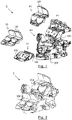
- the figure 1 illustrates an exploded view of the light module 1, while the picture 2 represents the light module 1 in which all the elements are assembled.
- the various elements of the light module 1 are described in detail below.
- the optical module 10 comprises a first reflector 100 provided with at least one light source.
- the additional optical module 40 comprises a second reflector 400 provided with at least one light source.
- the optical modules 10 and 40 include a plurality of light sources.
- the light sources are semiconductor emitter chips.
- a semiconductor emitter chip is part of a light-emitting diode.
- light-emitting diode we mean any type of light-emitting diode, whether in non-limiting examples LED (“Light Emitting Diode”), OLED (“organic LED”), AMOLED (Active-Matrix-Organic LED), or FOLED (Flexible OLED).
- LED Light Emitting Diode
- OLED organic LED
- AMOLED Active-Matrix-Organic LED
- FOLED Fluor
- Each optical module 10 and 40 further comprises at least one printed circuit board 305 and 405 respectively, also called PCB (“Printed Circuit Board”) to which the light sources are connected.
- PCB printed Circuit Board
- Each printed circuit board 305 and 405 is arranged respectively on the radiator 30 and 41 associated with each optical module 30 and 40.
- the first cut-off beam 101 and the second cut-off beam 401 are suitable for performing together a first photometric function f1 which is a dipped beam.
- the first cutoff beam 101 is a cutoff beam of which at least one portion is flat.
- the cutoff of the first cutoff beam 101 is an entirely flat upper cutoff
- the second cutoff beam 401 is a cutoff beam of which a portion is oblique.
- the first cutoff beam 101 is of the “flat” type
- the second cutoff beam is of the “kink” type.
- the cutoff of the second cutoff beam 401 is an entirely flat upper cutoff, and the first cutoff beam 101 is a cutoff beam of which a portion is oblique.
- the first cutoff beam 101 is of the “kink” type, while the second cutoff beam is of the “flat” type.
- the cutoff of the first cutoff beam 101 is an entirely flat upper cutoff, and the second cutoff beam 401 is also a flat cutoff beam.
- the first embodiment variant is illustrated in the picture 3 .
- the picture 3 illustrates a screen E disposed 25 meters from the light module 1 onto which the first and second cutoff beams 101 and 401 are projected.
- the first cutoff beam 101 comprises two flat portions 101a and 101b.
- the first cutoff beam 101 thus comprises an entirely flat upper cutoff.
- the second cutoff beam 401 comprises a portion 401a which is flat 401a and a portion 401b which is oblique.
- the two portions 101a and 101b of the cut-off beam are located at a distance d from a reference position P.
- the radiator 30-support plate 20 assembly will make it possible to position the first cut-off beam 101 produced by said optical module 10 at said reference position P.
- the assembly will make it possible to adjust the position of the first cut-off beam 101 so that the distance d is equal to 0.
- the position of the first beam will be able to be adjusted along the horizontal axis YY' illustrated on the picture 3 .
- the reference position P corresponds to a position in which a part 101a of the cutoff of the first beam is substantially superimposed on a part 401a of the cutoff of the second beam 401, in particular when the beams 101 and 401 are projected on the screen E placed 25m from the light module 1.
- the reference position P corresponds to a position in which a part 101a of the cutoff of the first beam is substantially superimposed on a part 401a of the cutoff of the second beam 401, in particular when the beams 101 and 401 are projected on the screen E placed 25m from the light module 1.
- the superimposition supports a tolerance of plus or minus 0.5° of the first beam with respect to the second beam.
- the reference position P corresponds to a horizontal part 401a of the second cut-off beam 400.
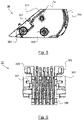
- the support plate 20 is illustrated on the figure 4a , 4b and 7 to 10 according to a non-limiting embodiment. On the figure 4 also illustrated is the radiator 30 which is positioned in the support plate 20.
- the support plate 20 comprises a first surface 200.
- This first surface 200 together with means for adjusting the radiator will make it possible to pivot the radiator 30 in rotation, so as to adjust the position of the first cut-off beam 101 to the reference position P described previously.
- the first surface 200 is cylindrical in shape with a circular directrix. This makes it possible to optimize the contact surface under the cooling fins 306 as illustrated on the figures 7 to 10 .
- the support plate 20 comprises two first surfaces 200.
- a slide 201 is provided with a rear stop.
- the opening makes it possible to have access to the first interface zone 302 (described later) after a manual rotation.
- the surface 202 has a U-shaped outline that forms the opening.
- the slide 201 is adapted to receive a male pivot pin 301 (described later) of the radiator 30. It will make it possible to block the radiator vertically and longitudinally at a given position and together with the male pin 301 to allow a rotation of the radiator 30 around an axis of rotation Ax passing through the center of said male pin 301.
- the slide assembly 201-male pin 301 thus forms a pivot connection.
- the screw barrel 204 is adapted to receive a fixing means 205 (described later) to lock the radiator 30 in position.
- the support plate 20 further comprises a second surface 203 facing the first surface 200, the two surfaces 200, 203 forming a guide groove for the rotation adjustment means 300 (described later ) of said radiator 30.
- the second surface 203 is cylindrical in shape with a circular directrix.
- the heater is shown on the figure 5 (side view) and 6 (rear side view).
- the shapes of the first surface 200 and of the adjustment means 300 are complementary to each other.
- the rotation adjustment means 300 are cylindrical in shape with a circular director as illustrated in the figure 5 .
- the rotation adjustment means 300 comprise two guide fins 300 of the radiator 30, in particular distributed on either side of the cooling fins 306.
- These guide fins 300 will come into contact with the first surface 200 and the support plate 20 and will make it possible to adjust the position of the first cut-off beam 101.
- These guide fins 300 also allow better heat dissipation from the radiator 30 because the air flow produced by a fan (not shown) coupled to the radiator 30 will cross said guide fins 300 vertically.
- At least one guide fin 300 of the radiator 30 is further adapted to receive a fixing means 205 (described later) inserted into the screw barrel 204 of said support plate 20.
- the radiator 30 comprises two guide fins 300 each adapted to receive a fixing means 205.
- the guide fins 300 each comprise an opening provided for this purpose.
- the rotation adjustment means 300 further comprise rear cooling fins 306 which have a cylindrical profile. This makes it possible to optimize the shape of the fins with respect to the available space.
- the radiator further comprises at least one additional interface zone 303 adapted to cooperate with an adjustment tool so as to actuate the rotation of the adjustment means 300 around the axis of rotation Ax.
- This interface zone 303 makes it possible, together with the first interface zone 302, to perform a fine rotation of the radiator 30 when it is in position in said support plate 20.
- the radiator 30 comprises two additional interface zones 303.
- the assembly of the elements of the light module 1 make it possible to position the first cut-off beam 101 of the “flat” type with respect to the second cut-off beam of the “kink” type.
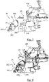
- the figure 7 illustrates the assembly of the radiator 30 on the support plate 20 according to a first assembly step.
- this first step is carried out by an operator manually.
- the radiator 30 only equipped with the PCB, that is to say without the optical module 10, is inserted into the support plate 20 in a horizontal direction as indicated by the arrow referenced a1.
- each male pivot pin 301 which is inserted into each slide 201 associated with the support plate 20.
- Each male pivot pin 301 thus slides along said slide 201 and reaches the end of its travel on the rear stop of said slide 201.
- the guide fins 300 come into contact with the first cylindrical surface 200 of the support plate 20 and due to their cylindrical shape (in the non-limiting embodiment illustrated), the surface of the guide fins 300 substantially conforms to the first surface cylindrical 200
- the first interface zone 302 is arranged, after the contact between the rotation adjustment means 300 of the radiator 30 and the first surface 200 of the support plate 20, at the level of the opening 202.
- the figure 8 illustrates the assembly of the radiator 30 on the support plate 20 according to a second assembly step.
- this second step is also carried out manually by an operator. According to this second step, the operator rotates the radiator 30 with his hand.
- the guide fins 300 pivot along the axis of rotation Ax which is an axis defined by the pivot connection formed by the slide assembly 201-male pivot pin.
- the arrow referenced a2 indicates the direction of rotation of the guide fins 300.
- the radiator 30 thus pivots until it reaches a so-called horizontal position.
- This pivoting makes it possible to adjust the radiator 30 and thus makes it possible to move the first cut-off beam 101 along a horizontal axis YY' (of the screen E illustrated on the picture 3 ) so that at least a part (here 101A) of said cut-off beam 101 reaches the reference position P.
- the figure 9 illustrates the assembly of the optical module 10 on the support plate 20 according to a third assembly step.
- this third step is also carried out manually by an operator.
- the operator assembles the optical module 10 here with its reflector 100 on the radiator 30.
- the arrow referenced a3 indicates the assembly direction which is perpendicular to the surface of the PCB.
- the printed circuit board 305 has been assembled beforehand, either on the radiator 30 at the location 307 which is dedicated to it, or on the optical module 10 itself.
- the figure 10 illustrates the assembly of the radiator 30 on the support plate 20 according to a fourth assembly step.
- this fourth step is carried out by means of a machine.
- This step makes it possible to fine-tune, by means of the first two interface zones 302, the position of the first cut-off beam 101 produced by the optical module 10 at the reference position P described above.
- the light sources of the two optical modules 101 and 401 are switched on so that they respectively produce the first cut-off beam 101 and the second cut-off beam 401.
- the switching on of the light sources is carried out successively so as to clearly observe the alignment of the cut-offs of the cut-off beams 101 and 401.
- the machine will be able to superimpose part 101a of the first cutoff beam 101 on part 401a of the second cutoff beam 401 according to the desired tolerance.
- the machine can also use the additional interface zones 303 described above to perform fine adjustment.
- the figures 11 to 13 illustrate the assembly of the radiator 30 on the support plate 20 according to a fifth assembly step.
- this fifth step is carried out by means of a machine.
- This step allows the radiator 30 to be clamped to the support plate 20.
- each fastening means 205 is inserted into the associated screw barrel 204 of the support plate 20 and into the dedicated opening of the associated guide fin 300 of the radiator 30.
- the fixing means 205 is a screw.
- the guide fins 300 are thus sandwiched between the cylindrical surfaces 200 and the fixing means 205, as illustrated in the top view figure 12 .
- the fixing means 205 apply a force so as to press the guide fins 300 against the cylindrical surfaces 200.
- the fixing means 205 are also illustrated on the rear view of the figure 13 .
- the radiator 30 is thus locked in position on the support plate 20 and thus no longer has any mechanical play.
- the assembly of the entire light module 1 is complete.
- the support plate 20 does not include a second surface 203.
- the cutoff of the first cutoff beam is a lower cutoff.
- the cutoff of the first cutoff beam is an entirely flat lower cutoff.
- the cutoff of the second cutoff beam is a lower cutoff.
- the cutoff of the second cutoff beam is an entirely flat lower cutoff.
- the first surface 200, the second surface 203 and the adjustment means 300 have a flat shape.
Description
La présente invention concerne un module lumineux pour véhicule automobile.The present invention relates to a light module for a motor vehicle.
Elle trouve une application particulière mais non limitative dans les dispositifs d'éclairage, tels que des projecteurs de véhicule automobile.It finds a particular but non-limiting application in lighting devices, such as motor vehicle headlamps.
Des modules lumineux pour véhicules automobiles sont décrits dans les documents
Un autre module lumineux pour véhicule automobile est décrit dans la demande de brevet
- au moins un module optique adapté pour produire un premier faisceau ;
- une platine support pour un radiateur ; et
- un radiateur adapté pour recevoir ledit module optique et comprenant des ailettes de refroidissement.
- at least one optical module adapted to produce a first beam;
- a support plate for a radiator; and
- a radiator adapted to receive said optical module and comprising cooling fins.
Une platine support est de forme sphérique. Elle comporte une glissière pour un ajustement selon une première direction donnée du radiateur dans la platine support, et une première rainure perpendiculaire à ladite glissière pour un ajustement selon une deuxième direction donnée du radiateur dans la platine support.A support plate is spherical in shape. It comprises a slide for adjustment in a first given direction of the radiator in the support plate, and a first groove perpendicular to said slide for adjustment in a second given direction of the radiator in the support plate.
Le module lumineux comprend en outre :
- un élément bloquant qui est adapté pour être pris en sandwich entre le radiateur et la platine support ; et
- un moyen de fixation du radiateur sur la platine support.
- a blocking element which is adapted to be sandwiched between the radiator and the support plate; and
- a means for fixing the radiator to the support plate.
Selon cet état de la technique antérieur, le module lumineux comprend cinq modules, cinq radiateurs associés, cinq platines support associées, cinq éléments bloquants et cinq moyens de fixation.According to this state of the prior art, the light module comprises five modules, five associated radiators, five associated support plates, five blocking elements and five fastening means.
Cela permet de réaliser une bande de lumière comprenant cinq faisceaux lumineux. Combinée avec un module optique permettant de réaliser un faisceau à coupure dont une portion est oblique, la bande de lumière permet de réaliser une fonction photométrique qui est un feu de croisement. Les cinq faisceaux doivent être ajustés entre eux selon un axe vertical et avec le faisceau à coupure selon un axe horizontal, ce qui est réalisable grâce aux deux directions possibles pour déplacer le radiateur dans la platine support.This makes it possible to produce a strip of light comprising five light beams. Combined with an optical module making it possible to produce a cut-off beam, a portion of which is oblique, the strip of light makes it possible to produce a photometric function which is a dipped beam. The five beams must be adjusted between them along a vertical axis and with the cut-off beam along a horizontal axis, which is achievable thanks to the two possible directions for moving the radiator in the support plate.
Un inconvénient de cet état de la technique est que ce module lumineux comprend un grand nombre de pièces mécaniques ce qui rend l'assemblage du module lumineux complexe et long.A drawback of this state of the art is that this light module comprises a large number of mechanical parts, which makes assembly of the light module complex and time-consuming.
Dans ce contexte, la présente invention vise à résoudre l'inconvénient précédemment mentionné.In this context, the present invention aims to solve the aforementioned drawback.
A cette fin l'invention propose un module lumineux pour véhicule automobile comprenant :
- au moins un module optique adapté pour produire un premier faisceau à coupure ;
- une platine support pour un radiateur ;
- un radiateur adapté pour recevoir ledit module optique ;
- ladite platine support comprenant une première surface; caractérisé en ce que
- ledit radiateur comprend des moyens de réglage en rotation adaptés pour :
- entrer en contact avec la première surface de ladite platine support ; et
- pivoter selon un axe de rotation déterminé de sorte à positionner le premier faisceau à coupure produit par ledit module optique à une position de référence.
- at least one optical module adapted to produce a first cut-off beam;
- a support plate for a radiator;
- a radiator adapted to receive said optical module;
- said support plate comprising a first surface; characterized in that
- said radiator comprises rotation adjustment means suitable for:
- come into contact with the first surface of said support plate; and
- pivoting along a determined axis of rotation so as to position the first cut-off beam produced by said optical module at a reference position.
Ainsi, comme on va le voir en détail ci-après, l'assemblage des éléments du module lumineux est simplifié car le nombre de pièces mécaniques a été réduit et il n'existe plus qu'un ajustement du radiateur par rapport à la platine support selon un axe de rotation donné.Thus, as we will see in detail below, the assembly of the elements of the light module is simplified because the number of mechanical parts has been reduced and there is only one adjustment of the radiator relative to the support plate. along a given axis of rotation.
Selon des modes de réalisation non limitatifs, le module lumineux peut comporter en outre une ou plusieurs caractéristiques supplémentaires parmi les suivantes :
- Dans un mode de réalisation non limitatif, le module optique comprend un premier réflecteur muni d'au moins une source lumineuse.
- Dans un mode de réalisation non limitatif, le premier faisceau à coupure est un faisceau à coupure dont au moins une portion est plate.
- Dans une variante de réalisation non limitative, la coupure du premier faisceau à coupure est une coupure supérieure entièrement plate.
- Dans un mode de réalisation non limitatif, les moyens de réglage en rotation comprennent deux ailettes de guidage du radiateur, notamment réparties de part et d'autre des ailettes de refroidissement.
- In a non-limiting embodiment, the optical module comprises a first reflector provided with at least one light source.
- In a non-limiting embodiment, the first cutoff beam is a cutoff beam of which at least one portion is flat.
- In a non-limiting alternative embodiment, the cutoff of the first cutoff beam is an entirely flat upper cutoff.
- In one non-limiting embodiment, the rotation adjustment means comprise two radiator guide fins, in particular distributed on either side of the cooling fins.
Les formes de la première surface et des moyens de réglage sont avantageusement complémentaires. Dans un mode de réalisation non limitatif, la première surface et les moyens de réglage en rotation sont de forme cylindrique de directrice circulaire.The shapes of the first surface and of the adjustment means are advantageously complementary. In a non-limiting embodiment, the first surface and the rotation adjustment means are cylindrical in shape with a circular director.
Dans un mode de réalisation non limitatif,
- la platine support comprend en outre au moins une glissière; et
- le radiateur comprend en outre un pion mâle pivot adapté pour s'insérer dans ladite glissière de ladite platine support.
- the support plate further comprises at least one slide; and
- the radiator further comprises a male pivot pin adapted to be inserted into said slideway of said support plate.
Dans une variante de réalisation non limitative,
- la platine support comprend deux glissières; et
- le radiateur comprend deux pions mâles pivot adaptés pour s'insérer respectivement dans lesdits glissières.
- the support plate comprises two slides; and
- the radiator comprises two male pivot pins adapted to be inserted respectively into said slideways.
Dans un mode de réalisation non limitatif, le radiateur comprend en outre une première zone d'interface adaptée pour coopérer avec un outil de réglage de sorte à actionner la rotation des moyens de réglages autour de l'axe de rotation.In a non-limiting embodiment, the radiator further comprises a first interface zone adapted to cooperate with an adjustment tool so as to actuate the rotation of the adjustment means around the axis of rotation.
Dans un mode de réalisation non limitatif,
- la platine support comprend en outre une surface munie d'un ajour située en avant de la première surface ; et ;
- la première zone d'interface est disposée, après le contact entre les moyens de réglage en rotation du radiateur et la première surface de la platine support, au niveau de l'ajour.
- the support plate further comprises a surface provided with an opening located in front of the first surface; and ;
- the first interface zone is arranged, after the contact between the means for adjusting the rotation of the radiator and the first surface of the support plate, at the level of the opening.
Dans un exemple non limitatif, la surface comporte un contour en forme de U qui forme l'ajour.In a non-limiting example, the surface has a U-shaped contour which forms the opening.
Dans un mode de réalisation non limitatif, le radiateur comprend en outre une zone d'interface supplémentaire adaptée pour coopérer avec un outil de réglage de sorte à actionner la rotation des moyens de réglage autour de l'axe de rotation.In a non-limiting embodiment, the radiator further comprises an additional interface zone adapted to cooperate with an adjustment tool so as to actuate the rotation of the adjustment means around the axis of rotation.
Dans un mode de réalisation non limitatif,
- la platine support comprend en outre un fût de vissage; et
- une ailette de guidage du radiateur est en outre adaptée pour recevoir un moyen de fixation inséré dans le fût de vissage de ladite platine support.
- the support plate further comprises a screw barrel; and
- a radiator guide fin is also adapted to receive a fixing means inserted into the screw shaft of said support plate.
Dans un mode de réalisation non limitatif, la platine support comprend en outre une deuxième surface en regard de la première surface, les deux surfaces formant une gorge de guidage pour les moyens de réglage en rotation dudit radiateur.In a non-limiting embodiment, the support plate further comprises a second surface facing the first surface, the two surfaces forming a guide groove for the means for adjusting the rotation of said radiator.
Dans un mode de réalisation non limitatif, la deuxième surface est de forme cylindrique de directrice circulaire.In a non-limiting embodiment, the second surface is cylindrical in shape with a circular directrix.
Dans un mode de réalisation non limitatif, la platine support est en outre adaptée pour recevoir un module optique supplémentaire adapté pour produire un deuxième faisceau à coupure.In a non-limiting embodiment, the support plate is also suitable for receiving an additional optical module suitable for producing a second cut-off beam.
Dans un mode de réalisation non limitatif, le module optique comprend un deuxième réflecteur muni d'au moins une source lumineuse.In a non-limiting embodiment, the optical module comprises a second reflector provided with at least one light source.
Dans un mode de réalisation non limitatif, le deuxième faisceau à coupure est un faisceau à coupure dont une portion est oblique. En variante, le deuxième faisceau à coupure peut être un faisceau à coupure plate.In a non-limiting embodiment, the second cutoff beam is a cutoff beam, a portion of which is oblique. As a variant, the second cutoff beam can be a flat cutoff beam.
Dans un mode de réalisation non limitatif, la position de référence correspond à une partie horizontale du deuxième faisceau à coupure.In a non-limiting embodiment, the reference position corresponds to a horizontal part of the second cut-off beam.
Dans un mode de réalisation non limitatif, la position de référence correspond à une position dans laquelle une partie de la coupure du premier faisceau est sensiblement superposée à une partie de la coupure du deuxième faisceau, notamment lorsque les faisceaux sont projetés sur un écran disposé à 25m du module lumineux. La superposition supporte une tolérance de plus ou moins 0.5° du premier faisceau par rapport au deuxième faisceau.In a non-limiting embodiment, the reference position corresponds to a position in which a part of the cut-off of the first beam is substantially superimposed on a part of the cut-off of the second beam, in particular when the beams are projected on a screen arranged at 25m from the light module. The superimposition supports a tolerance of plus or minus 0.5° of the first beam with respect to the second beam.
Dans un mode de réalisation non limitatif, le premier faisceau à coupure et le deuxième faisceau à coupure sont adaptés pour réaliser ensemble une première fonction photométrique qui est un feu de croisement.In a non-limiting embodiment, the first cut-off beam and the second cut-off beam are suitable for performing together a first photometric function which is a dipped beam.
Dans un mode de réalisation non limitatif, le radiateur comprend en outre au moins une carte à circuit imprimé sur laquelle est connectée au moins une source lumineuse.In one non-limiting embodiment, the radiator further comprises at least one printed circuit board to which at least one light source is connected.
Dans un mode de réalisation non limitatif, ladite au moins une source lumineuse est une puce émettrice semi-conductrice.In a non-limiting embodiment, said at least one light source is a semiconductor emitter chip.
Dans un mode de réalisation non limitatif, une puce émettrice semi-conductrice fait partie d'une diode électroluminescente.In one non-limiting embodiment, a semiconductor transmitter chip is part of a light emitting diode.
Il est également proposé un dispositif d'éclairage pour véhicule automobile comprenant un module lumineux selon l'une quelconque des caractéristiques précédentes.There is also proposed a lighting device for a motor vehicle comprising a light module according to any one of the preceding characteristics.
L'invention et ses différentes applications seront mieux comprises à la lecture de la description qui suit et à l'examen des figures qui l'accompagnent.
- la
figure 1 représente un éclaté d'un module lumineux pour véhicule automobile selon un mode de réalisation non limitatif de l'invention, ledit module lumineux comprenant au moins un module optique, une platine support et un radiateur ; - la
figure 2 représente le module lumineux de lafigure 1 assemblé, selon un mode de réalisation non limitatif ; - la
figure 3 est un schéma d'un écran sur lequel sont projetés un premier faisceau à coupure du module optique desfigures 1 et 2 , et un deuxième faisceau à coupure d'un module supplémentaire, selon un mode de réalisation non limitatif ; - la
figure 4a représente la platine support du module lumineux avec le radiateur desfigures 1 et 2 , selon un mode de réalisation non limitatif ; - la
figure 4b représente la face arrière de la platine support du module lumineux desfigures 1 et 2 , selon un mode de réalisation non limitatif ; - la
figure 5 représente une vue de profil du radiateur du module lumineux desfigures 1 et 2 , selon un mode de réalisation non limitatif ; - la
figure 6 représente une vue arrière du radiateur du module lumineux desfigures 1 et 2 , selon un mode de réalisation non limitatif ; - la
figure 7 représente une vue de profil du radiateur et de la platine support du module lumineux desfigures 1 et 2 selon une première étape d'assemblage, selon un mode de réalisation non limitatif ; - la
figure 8 représente une vue de profil du radiateur et de la platine support du module lumineux desfigures 1 et 2 selon une deuxième étape d'assemblage, selon un mode de réalisation non limitatif ; - la
figure 9 représente une vue de profil du radiateur et de la platine support du module lumineux desfigures 1 et 2 selon une troisième étape d'assemblage, selon un mode de réalisation non limitatif ; - la
figure 10 représente une vue de profil du radiateur et de la platine support du module lumineux desfigures 1 et 2 selon une quatrième étape d'assemblage, selon un mode de réalisation non limitatif ; - la
figure 11 représente une vue de profil du radiateur et de la platine support du module lumineux desfigures 1 et 2 selon une cinquième étape d'assemblage, selon un mode de réalisation non limitatif ; - la
figure 12 représente une vue de dessus du radiateur et de la platine support du module lumineux desfigures 1 et 2 selon une cinquième étape d'assemblage, selon un mode de réalisation non limitatif ; et - la
figure 13 représente une vue arrière du radiateur et de la platine support du module lumineux desfigures 1 et 2 selon une cinquième étape d'assemblage, selon un mode de réalisation non limitatif.
- the
figure 1 shows an exploded view of a light module for a motor vehicle according to a non-limiting embodiment of the invention, said light module comprising at least one optical module, a support plate and a radiator; - the
figure 2 represents the light module of thefigure 1 assembled, according to a non-limiting embodiment; - the
picture 3 is a diagram of a screen onto which are projected a first cut-off beam from the optical module of thefigures 1 and 2 , and a second cut-off beam of an additional module, according to a non-limiting embodiment; - the
figure 4a represents the light module support plate with the radiator of thefigures 1 and 2 , according to a non-limiting embodiment; - the
figure 4b represents the rear face of the light module support plate for thefigures 1 and 2 , according to a non-limiting embodiment; - the
figure 5 shows a profile view of the radiator of the light module of thefigures 1 and 2 , according to a non-limiting embodiment; - the
figure 6 shows a rear view of the heatsink of the light module of thefigures 1 and 2 , according to a non-limiting embodiment; - the
figure 7 shows a profile view of the radiator and the light module support plate of thefigures 1 and 2 according to a first assembly step, according to a non-limiting embodiment; - the
figure 8 shows a profile view of the radiator and the light module support plate of thefigures 1 and 2 according to a second assembly step, according to a non-limiting embodiment; - the
figure 9 shows a profile view of the radiator and the light module support plate of thefigures 1 and 2 according to a third assembly step, according to a non-limiting embodiment; - the
figure 10 shows a profile view of the radiator and the light module support plate of thefigures 1 and 2 according to a fourth assembly step, according to a non-limiting embodiment; - the
figure 11 shows a side view of the radiator and the light module support plate of thefigures 1 and 2 according to a fifth assembly step, according to a non-limiting embodiment; - the
figure 12 shows a top view of the heatsink and the light module support plate of thefigures 1 and 2 according to a fifth assembly step, according to a non-limiting embodiment; and - the
figure 13 shows a rear view of the heatsink and the light module support plate of thefigures 1 and 2 according to a fifth assembly step, according to a non-limiting embodiment.
Les éléments identiques, par structure ou par fonction, apparaissant sur différentes figures conservent, sauf précision contraire, les mêmes références.Identical elements, by structure or by function, appearing in different figures retain, unless otherwise specified, the same references.
Le module lumineux 1 pour véhicule automobile V selon l'invention est décrit en référence aux
Par véhicule automobile, on entend tout type de véhicule motorisé.
Un dispositif d'éclairage (non illustré) pour véhicule automobile V comprend le module lumineux 1. Dans un exemple non limitatif, le dispositif d'éclairage est un projecteur.The
Motor vehicle means any type of motorized vehicle.
A lighting device (not shown) for a motor vehicle V comprises the
Le module lumineux 1 comprend :
- au moins
un module optique 10 adapté pour produire un premier faisceau à coupure 101 ; une platine support 20 pourun radiateur 30 ;un radiateur 30 adapté pour recevoir leditmodule optique 10.
- at least one
optical module 10 adapted to produce a first cut-off beam 101; - a
support plate 20 for aradiator 30; - a
radiator 30 adapted to receive saidoptical module 10.
Tel qu'illustré sur les
- un module optique supplémentaire 40 adapté pour produire un deuxième faisceau à coupure 401 ;
un radiateur 41 adapté pour recevoir leditmodule optique supplémentaire 40.
- an additional
optical module 40 adapted to produce a second cut-off beam 401; - a
radiator 41 adapted to receive said additionaloptical module 40.
La
Les différents éléments du module lumineux 1 sont décrits en détail ci-après.The various elements of the
Dans un mode de réalisation non limitatif, le module optique 10 comprend un premier réflecteur 100 muni d'au moins une source lumineuse.In a non-limiting embodiment, the
De même, dans un mode de réalisation non limitatif, le module optique supplémentaire 40 comprend un deuxième réflecteur 400 muni d'au moins une source lumineuse.Similarly, in a non-limiting embodiment, the additional
Dans un mode de réalisation non limitatif, les modules optiques 10 et 40 comprennent une pluralité de sources lumineuses.In a non-limiting embodiment, the
Dans un mode de réalisation non limitatif, les sources lumineuses sont des puces émettrices semi-conductrices.In a non-limiting embodiment, the light sources are semiconductor emitter chips.
Dans une variante de réalisation non limitative, une puce émettrice semi-conductrice fait partie d'une diode électroluminescente.In a non-limiting alternative embodiment, a semiconductor emitter chip is part of a light-emitting diode.
Par diode électroluminescente, on entend tout type de diodes électroluminescentes, que ce soit dans des exemples non limitatifs des LED (« Light Emitting Diode »), des OLED (« organic LED »), des AMOLED (Active-Matrix-Organic LED), ou encore des FOLED (Flexible OLED).By light-emitting diode, we mean any type of light-emitting diode, whether in non-limiting examples LED (“Light Emitting Diode”), OLED (“organic LED”), AMOLED (Active-Matrix-Organic LED), or FOLED (Flexible OLED).
Chaque module optique 10 et 40 comprend en outre au moins une carte à circuit imprimé respectivement 305 et 405, appelée également carte PCB (« Printed Circuit Board» en anglais) à laquelle sont connectées les sources lumineuses.Each
Chaque carte à circuit imprimé 305 et 405 est disposée respectivement sur le radiateur 30 et 41 associé à chaque module optique 30 et 40.Each printed
Dans un mode de réalisation non limitatif, le premier faisceau à coupure 101 et le deuxième faisceau à coupure 401 sont adaptés pour réaliser ensemble une première fonction photométrique f1 qui est un feu de croisement.In a non-limiting embodiment, the first cut-
Dans un mode de réalisation non limitatif, le premier faisceau à coupure 101 est un faisceau à coupure dont au moins une portion est plate.In a non-limiting embodiment, the
Dans une première variante de réalisation non limitative, la coupure du premier faisceau à coupure 101 est une coupure supérieure entièrement plate, et le deuxième faisceau à coupure 401 est un faisceau à coupure dont une portion est oblique. Dans ce cas, le premier faisceau à coupure 101 est de type « flat », tandis que le deuxième faisceau à coupure est de type « kink ».In a first non-limiting variant embodiment, the cutoff of the
Dans une deuxième variante de réalisation non limitative, cela peut être l'inverse. La coupure du deuxième faisceau à coupure 401 est une coupure supérieure entièrement plate, et le premier faisceau à coupure 101 est un faisceau à coupure dont une portion est oblique. Dans ce cas, le premier faisceau à coupure 101 est de type « kink », tandis que le deuxième faisceau à coupure est de type « flat ».In a second non-limiting alternative embodiment, it may be the reverse. The cutoff of the
Dans une troisième variante de réalisation non limitative, la coupure du premier faisceau à coupure 101 est une coupure supérieure entièrement plate, et le deuxième faisceau à coupure 401 est également un faisceau à coupure plate.In a third non-limiting variant embodiment, the cutoff of the
La première variante de réalisation est illustrée sur la
La
Le deuxième faisceau à coupure 401 comprend une portion 401a qui est plate 401a et une portion 401b qui est oblique.The
Dans l'exemple non limitatif illustré, les deux portions 101a et 101b du faisceau à coupure sont situées à une distance d d'une position de référence P.In the non-limiting example illustrated, the two
Comme on va le voir par la suite, l'ensemble radiateur 30-platine support 20 va permettre de positionner le premier faisceau à coupure 101 produit par ledit module optique 10 à ladite position de référence P. L'ensemble va permettre d'ajuster la position du premier faisceau à coupure 101 de sorte que la distance d soit égale à 0. La position du premier faisceau va pouvoir être réglée selon l'axe horizontal Y-Y' illustré sur la
Dans un mode de réalisation non limitatif, tel qu'illustré sur la
La superposition supporte une tolérance de plus ou moins 0.5° du premier faisceau par rapport au deuxième faisceau.The superimposition supports a tolerance of plus or minus 0.5° of the first beam with respect to the second beam.
Dans l'exemple non limitatif illustré, la position de référence P correspond à une partie horizontale 401a du deuxième faisceau à coupure 400.In the non-limiting example illustrated, the reference position P corresponds to a
La platine support 20 est illustrée sur les
La platine support 20 comprend une première surface 200.The
Cette première surface 200 ensemble avec des moyens de réglage du radiateur (décrits plus loin), va permettre de faire pivoter en rotation le radiateur 30, de sorte à régler la position du premier faisceau à coupure 101 à la position de référence P décrite précédemment.This
Dans un mode de réalisation non limitatif, la première surface 200 est de forme cylindrique de directrice circulaire. Cela permet d'optimiser la surface de contact sous les ailettes de refroidissement 306 tel qu'illustré sur les
Dans l'exemple non limitatif illustré sur les
Dans des variantes de réalisation non limitatives, la platine support 20 comprend en outre :
- au moins une glissière 201 (illustré sur la
figure 7 par exemple) ; - au moins une
surface 202 munie d'un ajour située en avant de la premièresurface 200 ; - au moins un fût de vissage 204 (illustré sur la
figure 13 ).
- at least one slide 201 (shown in the
figure 7 for example) ; - at least one
surface 202 provided with an opening located in front of thefirst surface 200; - at least one screw barrel 204 (shown in the
figure 13 ).
Dans l'exemple non limitatif illustré sur la
- deux glissières 201 ;
deux surfaces 202 munies d'un ajour ;- deux fûts de vissage 204.
- two
slides 201; - two
surfaces 202 provided with an opening; - two screw barrels 204.
On notera qu'une glissière 201 est munie d'une butée arrière.It will be noted that a
On notera que l'ajour permet d'avoir accès à la première zone d'interface 302 (décrite plus loin) après une rotation manuelle.It will be noted that the opening makes it possible to have access to the first interface zone 302 (described later) after a manual rotation.
Dans un mode de réalisation non limitatif, la surface 202 comporte un contour en forme de U qui forme l'ajour.In a non-limiting embodiment, the
La glissière 201 est adaptée pour recevoir un pion mâle pivot 301 (décrit plus loin) du radiateur 30. Elle va permettre de bloquer verticalement et longitudinalement le radiateur à une position donnée et ensemble avec le pion mâle 301 de permettre une rotation du radiateur 30 autour d'un axe de rotation Ax passant par le centre dudit pion mâle 301. L'ensemble glissière 201-pion mâle 301 forme ainsi une liaison pivot.The
Le fût de vissage 204 est adapté pour recevoir un moyen de fixation 205 (décrit plus loin) pour bloquer le radiateur 30 en position.The
Dans un mode de réalisation non limitatif, la platine support 20 comprend en outre une deuxième surface 203 en regard de la première surface 200, les deux surfaces 200, 203 formant une gorge de guidage pour les moyens de réglage en rotation 300 (décrits plus loin) dudit radiateur 30.In a non-limiting embodiment, the
Dans un mode de réalisation non limitatif, la deuxième surface 203 est de forme cylindrique de directrice circulaire.In a non-limiting embodiment, the
Le radiateur est illustré sur les
Le radiateur 30 comprend :
un emplacement 307 pour la carte àcircuit imprimé 305.L'emplacement 307 permet également de recevoir lemodule optique 10 qui se positionne au dessus la carte àcircuit imprimé 305.
Dans un mode de réalisation non limitatif, le radiateur 30 comprend en outre des ailettes de refroidissement 306 adaptées pour refroidir les composants de la carte àcircuit imprimé 305.
- a
slot 307 for the printedcircuit board 305. Theslot 307 also makes it possible to receive theoptical module 10 which is positioned above the printedcircuit board 305.
In one non-limiting embodiment, theheatsink 30 further includes coolingfins 306 adapted to cool the components of the printedcircuit board 305.
Le radiateur 30 comprend en outre des moyens de réglage en rotation 300, adaptés pour :
- entrer en contact avec la première
surface 200 de ladite platinesupport 20 ; et - pivoter selon un axe de rotation déterminé Ax de sorte à positionner le premier faisceau à coupure 101 produit par
ledit module optique 10 à une position de référence P.
- come into contact with the
first surface 200 of saidsupport plate 20; and - pivot along a determined axis of rotation Ax so as to position the first cut-
off beam 101 produced by saidoptical module 10 at a reference position P.
On notera que les formes de la première surface 200 et des moyens de réglage 300 sont complémentaires l'une de l'autre.It will be noted that the shapes of the
Dans un mode de réalisation non limitatif, les moyens de réglage en rotation 300 sont de forme cylindrique de directrice circulaire tel qu'illustré sur la
Dans un mode de réalisation non limitatif, les moyens de réglage en rotation 300 comprennent deux ailettes de guidage 300 du radiateur 30, notamment réparties de part et d'autre des ailettes de refroidissement 306.In a non-limiting embodiment, the rotation adjustment means 300 comprise two
Ces ailettes de guidage 300 vont entrer en contact avec la première surface 200 et la platine support 20 et vont permettre de régler la position du premier faisceau à coupure 101.These guide
Ces ailettes de guidage 300 permettent également une meilleure dissipation thermique du radiateur 30 car le flux d'air produit par un ventilateur (non illustré) couplé au radiateur 30 va traverser verticalement lesdites ailettes de guidage 300.These guide
Dans un mode de réalisation non limitatif, au moins une ailette de guidage 300 du radiateur 30 est en outre adaptée pour recevoir un moyen de fixation 205 (décrit plus loin) inséré dans le fût de vissage 204 de ladite platine support 20. Dans l'exemple illustré sur la
Dans un mode de réalisation non limitatif, les moyens de réglage en rotation 300 comprennent en outre des ailettes de refroidissement arrière 306 qui ont un profil cylindrique. Cela permet d'optimiser la forme des ailettes par rapport à l'encombrement disponible.In a non-limiting embodiment, the rotation adjustment means 300 further comprise
Dans des modes de réalisation non limitatifs, le radiateur 30 comporte en outre :
- au moins un pion mâle
pivot 301 adapté pour s'insérer dans ladite glissière 201 de ladite platine support 20 (comme expliqué précédemment). - une
première zone d'interface 302 adaptée pour coopérer avec un outil de réglage, par exemple un tournevis, de sorte à actionner la rotation des moyens de réglage 300 autour de l'axe de rotation Ax selon des angles de faibles amplitudes et ainsi à permettre un réglage fin.
- at least one
male pivot pin 301 adapted to be inserted into saidslideway 201 of said support plate 20 (as explained previously). - a
first interface zone 302 adapted to cooperate with an adjustment tool, for example a screwdriver, so as to actuate the rotation of the adjustment means 300 around the axis of rotation Ax according to angles of small amplitudes and thus to allow fine tuning.
Dans l'exemple non limitatif illustré sur la
- deux pions mâles
pivots 301 répartis de chaque côté du radiateur 30 ; - deux premières zones d'interface 302 réparties de chaque côté du radiateur 30.
- two male pivot pins 301 distributed on each side of the
radiator 30; - two
first interface zones 302 distributed on each side of theradiator 30.
Dans un mode de réalisation non limitatif, le radiateur comprend en outre au moins une zone d'interface supplémentaire 303 adaptée pour coopérer avec un outil de réglage de sorte à actionner la rotation des moyens de réglage 300 autour de l'axe de rotation Ax. Cette zone d'interface 303 permet ensemble avec la première zone d'interface 302 d'effectuer une rotation fine du radiateur 30 lorsqu'il est en position dans ladite platine support 20.In a non-limiting embodiment, the radiator further comprises at least one
Dans l'exemple non limitatif illustré sur la
Après avoir présenté l'ensemble des éléments du module lumineux, les étapes d'assemblage desdits éléments sont présentées ci-après en référence aux
Dans le mode de réalisation non limitatif illustré, l'assemblage des éléments du module lumineux 1 permettent de positionner le premier faisceau à coupure 101 de type « flat » par rapport au deuxième faisceau à coupure de type « kink ».In the non-limiting embodiment illustrated, the assembly of the elements of the
Ces figures n'illustrent pas l'assemblage du deuxième radiateur 41 et du deuxième module optique 40 sur la platine support 20.These figures do not illustrate the assembly of the
Dans l'exemple non limitatif illustré sur les figures, ces deux éléments 41 et 40 ont été assemblés préalablement.In the non-limiting example illustrated in the figures, these two
La
Dans un mode de réalisation non limitatif, cette première étape est effectuée par un opérateur de manière manuelle.In a non-limiting embodiment, this first step is carried out by an operator manually.
Le radiateur 30 seulement équipé du PCB, c'est-dire sans le module optique 10, est inséré dans la platine support 20 selon une direction horizontale comme l'indique la flèche référencée a1.The
L'insertion se fait au moyen de chaque pion mâle pivot 301 qui s'insère dans chaque glissière 201 associée de la platine support 20.The insertion is done by means of each
Chaque pion mâle pivot 301 glisse ainsi le long de ladite glissière 201 et arrive en fin de course sur la butée arrière de ladite glissière 201.Each
Tel qu'illustré sur la
On s'assure ainsi que la première zone d'interface 302 est accessible quelque soit la position du radiateur 30.This ensures that the
La
Dans un mode de réalisation non limitatif, cette deuxième étape est effectuée également par un opérateur de manière manuelle. Selon cette deuxième étape, l'opérateur met en rotation le radiateur 30 avec la main.In a non-limiting embodiment, this second step is also carried out manually by an operator. According to this second step, the operator rotates the
Ainsi, les ailettes de guidage 300 pivotent selon l'axe de rotation Ax qui est un axe défini par la liaison pivot formée par l'ensemble glissière 201-pion mâle pivot. La flèche référencée a2 indique le sens de rotation des ailettes de guidage 300.Thus, the
Le radiateur 30 pivote ainsi jusqu'à arriver à une position dite horizontale.The
Ce pivotement permet de régler le radiateur 30 et permet ainsi de déplacer le premier faisceau à coupure 101 selon un axe horizontal Y-Y' (de l'écran E illustré sur la
La
Dans un mode de réalisation non limitatif, cette troisième étape est effectuée également par un opérateur de manière manuelle. Selon cette troisième étape, l'opérateur assemble le module optique 10 avec ici son réflecteur 100 sur le radiateur 30. La flèche référencée a3 indique la direction d'assemblage qui est perpendiculaire à la surface du PCB.In a non-limiting embodiment, this third step is also carried out manually by an operator. According to this third step, the operator assembles the
On notera que la carte à circuit imprimé 305 a été préalablement assemblée, soit sur le radiateur 30 à l'emplacement 307 qui lui est dédié, soit sur le module optique 10 lui-même.It will be noted that the printed
La
Dans un mode de réalisation non limitatif, cette quatrième étape est effectuée au moyen d'une machine.In a non-limiting embodiment, this fourth step is carried out by means of a machine.
Cette étape permet de régler au moyen des deux premières zones d'interface 302 de manière fine la position du premier faisceau à coupure 101 produit par le module optique 10 à la position de référence P décrite précédemment.This step makes it possible to fine-tune, by means of the first two
Pour effectuer cette étape, les sources lumineuses des deux modules optiques 101 et 401 sont allumées de sorte qu'elles produisent respectivement le premier faisceau à coupure 101 et le deuxième faisceau à coupure 401. Dans un mode de réalisation non limitatif, l'allumage des sources lumineuses est effectué successivement de sorte à bien observer l'alignement des coupures des faisceaux à coupure 101 et 401.To perform this step, the light sources of the two
De cette manière, la machine va pouvoir superposer la partie 101a du premier faisceau à coupure 101 sur la partie 401a du deuxième faisceau à coupure 401 selon la tolérance désiré.In this way, the machine will be able to superimpose
On notera que dans un mode de réalisation non limitatif, la machine peut utiliser également les zones d'interface supplémentaires 303 décrites précédemment pour effectuer un réglage fin.It will be noted that in a non-limiting embodiment, the machine can also use the
Les flèches référencées a4 indiquent ce réglage précis par la machine.The arrows referenced a4 indicate this precise adjustment by the machine.
Les
Dans un mode de réalisation non limitatif, cette cinquième étape est effectuée au moyen d'une machine.In a non-limiting embodiment, this fifth step is carried out by means of a machine.
Cette étape permet de brider le radiateur 30 sur la platine support 20.This step allows the
Lors de cette étape, chaque moyen de fixation 205 est inséré dans le fût de vissage 204 associé de la platine support 20 et dans l'ouverture dédiée de l'ailette de guidage 300 associée du radiateur 30.During this step, each fastening means 205 is inserted into the associated
Dans un mode de réalisation non limitatif, le moyen de fixation 205 est une vis.In a non-limiting embodiment, the fixing means 205 is a screw.
Les ailettes de guidage 300 sont ainsi prises en sandwich entre les surfaces cylindriques 200 et les moyens de fixation 205, tel qu'illustré sur la vue de dessus
Les moyens de fixation 205 sont également illustrés sur la vue arrière de la
Le radiateur 30 est ainsi bloqué en position sur la platine support 20 et ne présente ainsi plus aucun jeu mécanique.The
L'assemblage de l'ensemble du module lumineux 1 est terminé.The assembly of the entire
Bien entendu la description de l'invention n'est pas limitée aux modes de réalisation décrits ci-dessus.Of course, the description of the invention is not limited to the embodiments described above.
Ainsi, dans un mode de réalisation non limitatif, la platine support 20 ne comporte pas de deuxième surface 203.Thus, in a non-limiting embodiment, the
Ainsi, dans un mode de réalisation non limitatif, la coupure du premier faisceau à coupure est une coupure inférieure.Thus, in a non-limiting embodiment, the cutoff of the first cutoff beam is a lower cutoff.
Dans une variante de réalisation non limitative, la coupure du premier faisceau à coupure est une coupure inférieure entièrement plate.In a non-limiting alternative embodiment, the cutoff of the first cutoff beam is an entirely flat lower cutoff.
Ainsi, dans un mode de réalisation non limitatif, la coupure du deuxième faisceau à coupure est une coupure inférieure.Thus, in a non-limiting embodiment, the cutoff of the second cutoff beam is a lower cutoff.
Dans une variante de réalisation non limitative, la coupure du deuxième faisceau à coupure est une coupure inférieure entièrement plate.In a non-limiting alternative embodiment, the cutoff of the second cutoff beam is an entirely flat lower cutoff.
Ainsi, dans un mode de réalisation non limitatif, la première surface 200, la deuxième surface 203 et les moyens de réglage 300 ont une forme plane.Thus, in a non-limiting embodiment, the
Ainsi, l'invention décrite présente notamment les avantages suivants :
- elle permet de régler en rotation la position du radiateur 30 et donc la position du module optique 10 par rapport à la platine
support 20, et en conséquence elle permet de régler le premier faisceau à coupure selon un seul axe donné, ici horizontal (selon l'axe Y-Y' de l'écran E); - c'est une solution simple à mettre en œuvre qui ne nécessite pas un nombre important de pièces mécaniques à assembler ;
- l'assemblage par un opérateur humain est rapide à effectuer puisqu'il a moins de pièces à assembler que dans l'état de la technique antérieur décrit ;
- le bridage du radiateur est simple à effectuer.
- it makes it possible to adjust in rotation the position of the
radiator 30 and therefore the position of theoptical module 10 with respect to thesupport plate 20, and in consequently it makes it possible to adjust the first cut-off beam along a single given axis, here horizontal (along the YY' axis of the screen E); - it is a simple solution to implement which does not require a large number of mechanical parts to be assembled;
- assembly by a human operator is quick to perform since there are fewer parts to assemble than in the state of the prior art described;
- the clamping of the radiator is simple to carry out.
Claims (15)
- Lighting module (1) for automobile vehicles (V), including:- at least one optical module (10) adapted to produce a first cut-off beam (101);- a support plate (20) for a heatsink (30);- a heatsink (30) adapted to receive said optical module (10);- said support plate (20) including a first surface (200) ;characterized in that- said heatsink (30) includes rotational adjustment means (300) adapted:- to enter into contact with the first surface (200) of said support plate (20); and- to pivot about a particular rotation axis (Ax) so as to position the first cut-off beam (101) produced by said optical module (10) at a reference position (P).
- Lighting module (1) according to Claim 1, wherein the first cut-off beam (101) is a cut-off beam at least one portion (101a) of which is flat.
- Lighting module (1) according to Claim 1 or Claim 2, wherein the rotational adjustment means (300) include two fins (300) for guiding the heatsink (30), notably distributed on respective opposite sides of the cooling fins (306).
- Lighting module (1) according to Claim 3, wherein the first surface (200) and the rotational adjustment means (300) are of cylindrical shape with a circular section.
- Lighting module (1) according to any one of the preceding Claims 1 to 4, wherein:- the support plate (20) further includes at least one slide (201); and- the heatsink (30) further includes a male pivot pin (301) adapted to be inserted in said slide (201) of said support plate (20).
- Lighting module (1) according to any one of the preceding Claims 1 to 5, wherein the heatsink (30) further includes a first interface area (302) adapted to cooperate with an adjustment tool so as to actuate the rotation of the adjustment means (300) about the rotation axis (Ax).
- Lighting module (1) according to the preceding Claim 6, wherein:- the support plate (20) further includes a surface provided with an aperture (202) situated in front of the first surface (200); and- the first interface area (302) is disposed at the level of the aperture after the contact between the rotational adjustment means (300) of the heatsink (30) and the first surface (200) of the support plate (20).
- Lighting module (1) according to either one of Claims 6 or 7, wherein the heatsink (30) further includes an additional interface area (303) adapted to cooperate with an adjustment tool so as to actuate the rotation of the adjustment means (300) about the rotation axis (Ax).
- Lighting module (1) according to any one of the preceding Claims 1 to 8, wherein:- the support plate (20) further includes a screw pillar (204); and- a fin (300) for guiding the heatsink (30) is further adapted to receive fixing means (205) inserted in the screw pillar (204) of said support plate (20).
- Lighting module (1) according to any one of the preceding Claims 1 to 9, wherein the support plate (20) further includes a second surface (203) facing the first surface (200), the two surfaces (200, 203) forming a groove for guiding the means (300, 304) for rotational adjustment of said heatsink (30).
- Lighting module (1) according to any one of the preceding Claims 1 to 10, wherein the support plate (20) is further adapted to receive an additional optical module (40) adapted to produce a second cut-off beam (401) .
- Lighting module (1) according to the preceding Claim 11, wherein the second cut-off beam (401) is a cut-off beam a portion of which is oblique.
- Lighting module (1) according to Claim 11 or Claim 12, wherein the reference position (P) corresponds to a horizontal part (401a) of the second cut-off beam (401) .
- Lighting module (1) according to any one of the preceding Claims 11 to 13, wherein the first cut-off beam (101) and the second cut-off beam (401) are adapted to provide conjointly a first low beam photometric function (f1).
- Lighting device (2) for automobile vehicles (V) including a lighting module (1) according to any one of the preceding Claims 1 to 14.
Applications Claiming Priority (1)
| Application Number | Priority Date | Filing Date | Title |
|---|---|---|---|
| FR1550515A FR3032023B1 (en) | 2015-01-22 | 2015-01-22 | LUMINOUS MODULE FOR MOTOR VEHICLE |
Publications (2)
| Publication Number | Publication Date |
|---|---|
| EP3048359A1 EP3048359A1 (en) | 2016-07-27 |
| EP3048359B1 true EP3048359B1 (en) | 2022-09-14 |
Family
ID=52692942
Family Applications (1)
| Application Number | Title | Priority Date | Filing Date |
|---|---|---|---|
| EP16151615.8A Active EP3048359B1 (en) | 2015-01-22 | 2016-01-15 | Light module for a motor vehicle |
Country Status (4)
| Country | Link |
|---|---|
| US (1) | US9822945B2 (en) |
| EP (1) | EP3048359B1 (en) |
| CN (1) | CN105823023B (en) |
| FR (1) | FR3032023B1 (en) |
Families Citing this family (8)
| Publication number | Priority date | Publication date | Assignee | Title |
|---|---|---|---|---|
| EP3354967B1 (en) * | 2017-01-31 | 2021-09-01 | Marelli Automotive Lighting Italy S.p.A. | Rotating lighting module with welcome function and lighting device for vehicles |
| FR3088987B1 (en) * | 2018-11-23 | 2020-10-30 | Psa Automobiles Sa | REFLECTOR VEHICLE OPTICAL BLOCK FLOATING RELATIVE TO A MASK |
| CN111237715B (en) * | 2018-11-28 | 2023-08-15 | 法雷奥照明湖北技术中心有限公司 | Optical assembly, lighting and/or signalling device and vehicle |
| FR3100863A1 (en) | 2019-09-12 | 2021-03-19 | Psa Automobiles Sa | Modular light set |
| US11046235B2 (en) | 2019-11-13 | 2021-06-29 | James M. Aparo | Vehicle headlight assembly having an ejectable and replaceable lightbulb |
| US11028989B2 (en) | 2019-11-13 | 2021-06-08 | James M. Aparo | Vehicle headlight device having an ejectable and replaceable lightbulb assembly |
| DE102022109084A1 (en) | 2022-04-13 | 2023-10-19 | Marelli Automotive Lighting Reutlingen (Germany) GmbH | Mechanical adjustment of main light modules on fictitious axes of rotation |
| FR3137743A1 (en) * | 2022-07-11 | 2024-01-12 | Valeo Vision | Heat sink of light module for automobile vehicle and light module for automobile vehicle |
Family Cites Families (7)
| Publication number | Priority date | Publication date | Assignee | Title |
|---|---|---|---|---|
| DE102004062990A1 (en) * | 2004-12-22 | 2006-07-06 | Patent-Treuhand-Gesellschaft für elektrische Glühlampen mbH | Lighting device with at least one light emitting diode and vehicle headlights |
| US8534888B2 (en) | 2010-09-10 | 2013-09-17 | Koito Manufacturing Co., Ltd. | Optical unit for a vehicular lamp |
| FR2980419B1 (en) * | 2011-09-27 | 2014-05-09 | Valeo Vision | VEHICLE PROJECTOR MODULE MOUNTED ON SLIDERS, SUPPORT AND PROJECTOR CORRESPONDING |
| DE102012106313B4 (en) * | 2012-07-13 | 2022-06-09 | HELLA GmbH & Co. KGaA | Module assembly with adjustable semiconductor light modules for a headlight and method for adjustment |
| DE102012106314A1 (en) * | 2012-07-13 | 2014-01-16 | Hella Kgaa Hueck & Co. | Module assembly with pivotable semiconductor light modules for a headlight |
| DE102012107432A1 (en) | 2012-08-14 | 2014-05-15 | Hella Kgaa Hueck & Co. | Lighting system with a cooling device and an optical body |
| US9568160B2 (en) * | 2013-05-10 | 2017-02-14 | Grote Industries, Inc. | Lamp with a reflector |
-
2015
- 2015-01-22 FR FR1550515A patent/FR3032023B1/en active Active
-
2016
- 2016-01-15 EP EP16151615.8A patent/EP3048359B1/en active Active
- 2016-01-20 US US15/001,897 patent/US9822945B2/en active Active
- 2016-01-22 CN CN201610045926.1A patent/CN105823023B/en active Active
Also Published As
| Publication number | Publication date |
|---|---|
| CN105823023B (en) | 2020-08-11 |
| EP3048359A1 (en) | 2016-07-27 |
| FR3032023B1 (en) | 2017-02-10 |
| US9822945B2 (en) | 2017-11-21 |
| FR3032023A1 (en) | 2016-07-29 |
| US20160215951A1 (en) | 2016-07-28 |
| CN105823023A (en) | 2016-08-03 |
Similar Documents
| Publication | Publication Date | Title |
|---|---|---|
| EP3048359B1 (en) | Light module for a motor vehicle | |
| CA2810385C (en) | Optical module of an illuminating and/or signalling device of a motor vehicle | |
| EP2574503B1 (en) | Motor vehicle headlamp module with bayonet attachment, corresponding mounting and headlamp | |
| EP2574501B1 (en) | Lighting and/or signalling device for vehicle | |
| EP2598797B1 (en) | Optical module of an illuminating and/or signalling device of a motor vehicle | |
| EP2394850B1 (en) | Manually operable adjusting system shared by two lighting devices, one of which being automatically adjustable | |
| FR2965039A1 (en) | OPTICAL MODULE FOR A LIGHTING AND / OR SIGNALING DEVICE FOR A MOTOR VEHICLE | |
| FR2994788A1 (en) | LIGHTING MODULE COMPRISING A REMOTELY REMAINING CONTROL DEVICE ON A SUPPORT | |
| EP3771861B1 (en) | Lighting device | |
| EP3290270B1 (en) | Light device of a motor vehicle | |
| EP2578451B1 (en) | Actuator for vehicle headlight | |
| EP3543597B1 (en) | Lighting module provided with a micro-mirror array with optimised cooling | |
| FR3055688A1 (en) | MEDICAL LIGHTING DEVICE WITH LEDS ORIENTED BY PRE-CUTTED TONGUES IN A PRINTED CIRCUIT BOARD | |
| EP3251895B1 (en) | Lighting and/or signalling device for a motor vehicle | |
| EP3239598B1 (en) | Rotary light module | |
| FR3004396A1 (en) | PROJECTOR EQUIPPED WITH ESCAMOTABLE LIGHTING MODULES | |
| WO2020126823A1 (en) | Method for assembling a motor vehicle headlamp optical system and associated motor vehicle headlamp optical system | |
| EP2963335B1 (en) | Pivotal mounting of a motor vehicle lighting module | |
| EP3686478B1 (en) | Compact headlight having a pivoting plate | |
| EP3221185B1 (en) | Lighting unit for a vehicle and corresponding vehicle | |
| EP2842805B1 (en) | Light assembly with support device allowing the passage of an air flow to an automobile radiator | |
| FR2987909A1 (en) | Projection device for projecting holographic image e.g. text image, at rear part of vehicle i.e. car, has positioning unit for positioning light source and plates relative to support unit to generate image in selected place | |
| FR3091761A1 (en) | Retractable combiner device for head-up display system, head-up display system comprising such a device and vehicle equipped with said system | |
| FR3099107A1 (en) | DASHBOARD DESIGNED TO KEEP A NOMADIC MULTIMEDIA DEVICE IN A VEHICLE AND CORRESPONDING VEHICLE | |
| FR2964724A1 (en) | Optical module for lighting and signaling device e.g. headlight type light projector, of motor vehicle, has folding element fixed in module in motionless manner with respect to light source, where folding element is made by metal piece |
Legal Events
| Date | Code | Title | Description |
|---|---|---|---|
| PUAI | Public reference made under article 153(3) epc to a published international application that has entered the european phase |
Free format text: ORIGINAL CODE: 0009012 |
|
| AK | Designated contracting states |
Kind code of ref document: A1 Designated state(s): AL AT BE BG CH CY CZ DE DK EE ES FI FR GB GR HR HU IE IS IT LI LT LU LV MC MK MT NL NO PL PT RO RS SE SI SK SM TR |
|
| AX | Request for extension of the european patent |
Extension state: BA ME |
|
| STAA | Information on the status of an ep patent application or granted ep patent |
Free format text: STATUS: REQUEST FOR EXAMINATION WAS MADE |
|
| 17P | Request for examination filed |
Effective date: 20161216 |
|
| RBV | Designated contracting states (corrected) |
Designated state(s): AL AT BE BG CH CY CZ DE DK EE ES FI FR GB GR HR HU IE IS IT LI LT LU LV MC MK MT NL NO PL PT RO RS SE SI SK SM TR |
|
| STAA | Information on the status of an ep patent application or granted ep patent |
Free format text: STATUS: EXAMINATION IS IN PROGRESS |
|
| 17Q | First examination report despatched |
Effective date: 20190926 |
|
| STAA | Information on the status of an ep patent application or granted ep patent |
Free format text: STATUS: EXAMINATION IS IN PROGRESS |
|
| REG | Reference to a national code |
Ref country code: DE Ref legal event code: R079 Ref document number: 602016074954 Country of ref document: DE Free format text: PREVIOUS MAIN CLASS: F21S0008100000 Ipc: F21S0041147000 |
|
| RIC1 | Information provided on ipc code assigned before grant |
Ipc: F21S 41/39 20180101ALI20220221BHEP Ipc: F21S 41/43 20180101ALI20220221BHEP Ipc: F21S 41/36 20180101ALI20220221BHEP Ipc: F21S 45/48 20180101ALI20220221BHEP Ipc: F21S 41/32 20180101ALI20220221BHEP Ipc: F21S 45/49 20180101ALI20220221BHEP Ipc: F21S 41/19 20180101ALI20220221BHEP Ipc: F21S 41/153 20180101ALI20220221BHEP Ipc: F21S 41/147 20180101AFI20220221BHEP |
|
| GRAP | Despatch of communication of intention to grant a patent |
Free format text: ORIGINAL CODE: EPIDOSNIGR1 |
|
| STAA | Information on the status of an ep patent application or granted ep patent |
Free format text: STATUS: GRANT OF PATENT IS INTENDED |
|
| INTG | Intention to grant announced |
Effective date: 20220401 |
|
| GRAS | Grant fee paid |
Free format text: ORIGINAL CODE: EPIDOSNIGR3 |
|
| GRAA | (expected) grant |
Free format text: ORIGINAL CODE: 0009210 |
|
| STAA | Information on the status of an ep patent application or granted ep patent |
Free format text: STATUS: THE PATENT HAS BEEN GRANTED |
|
| AK | Designated contracting states |
Kind code of ref document: B1 Designated state(s): AL AT BE BG CH CY CZ DE DK EE ES FI FR GB GR HR HU IE IS IT LI LT LU LV MC MK MT NL NO PL PT RO RS SE SI SK SM TR |
|
| REG | Reference to a national code |
Ref country code: GB Ref legal event code: FG4D Free format text: NOT ENGLISH |
|
| REG | Reference to a national code |
Ref country code: CH Ref legal event code: EP |
|
| REG | Reference to a national code |
Ref country code: DE Ref legal event code: R096 Ref document number: 602016074954 Country of ref document: DE |
|
| REG | Reference to a national code |
Ref country code: IE Ref legal event code: FG4D Free format text: LANGUAGE OF EP DOCUMENT: FRENCH |
|
| REG | Reference to a national code |
Ref country code: AT Ref legal event code: REF Ref document number: 1518898 Country of ref document: AT Kind code of ref document: T Effective date: 20221015 |
|
| REG | Reference to a national code |
Ref country code: LT Ref legal event code: MG9D |
|
| REG | Reference to a national code |
Ref country code: NL Ref legal event code: MP Effective date: 20220914 |
|
| PG25 | Lapsed in a contracting state [announced via postgrant information from national office to epo] |
Ref country code: SE Free format text: LAPSE BECAUSE OF FAILURE TO SUBMIT A TRANSLATION OF THE DESCRIPTION OR TO PAY THE FEE WITHIN THE PRESCRIBED TIME-LIMIT Effective date: 20220914 Ref country code: RS Free format text: LAPSE BECAUSE OF FAILURE TO SUBMIT A TRANSLATION OF THE DESCRIPTION OR TO PAY THE FEE WITHIN THE PRESCRIBED TIME-LIMIT Effective date: 20220914 Ref country code: NO Free format text: LAPSE BECAUSE OF FAILURE TO SUBMIT A TRANSLATION OF THE DESCRIPTION OR TO PAY THE FEE WITHIN THE PRESCRIBED TIME-LIMIT Effective date: 20221214 Ref country code: LV Free format text: LAPSE BECAUSE OF FAILURE TO SUBMIT A TRANSLATION OF THE DESCRIPTION OR TO PAY THE FEE WITHIN THE PRESCRIBED TIME-LIMIT Effective date: 20220914 Ref country code: LT Free format text: LAPSE BECAUSE OF FAILURE TO SUBMIT A TRANSLATION OF THE DESCRIPTION OR TO PAY THE FEE WITHIN THE PRESCRIBED TIME-LIMIT Effective date: 20220914 Ref country code: FI Free format text: LAPSE BECAUSE OF FAILURE TO SUBMIT A TRANSLATION OF THE DESCRIPTION OR TO PAY THE FEE WITHIN THE PRESCRIBED TIME-LIMIT Effective date: 20220914 |
|
| REG | Reference to a national code |
Ref country code: AT Ref legal event code: MK05 Ref document number: 1518898 Country of ref document: AT Kind code of ref document: T Effective date: 20220914 |
|
| PG25 | Lapsed in a contracting state [announced via postgrant information from national office to epo] |
Ref country code: HR Free format text: LAPSE BECAUSE OF FAILURE TO SUBMIT A TRANSLATION OF THE DESCRIPTION OR TO PAY THE FEE WITHIN THE PRESCRIBED TIME-LIMIT Effective date: 20220914 Ref country code: GR Free format text: LAPSE BECAUSE OF FAILURE TO SUBMIT A TRANSLATION OF THE DESCRIPTION OR TO PAY THE FEE WITHIN THE PRESCRIBED TIME-LIMIT Effective date: 20221215 |
|
| PG25 | Lapsed in a contracting state [announced via postgrant information from national office to epo] |
Ref country code: SM Free format text: LAPSE BECAUSE OF FAILURE TO SUBMIT A TRANSLATION OF THE DESCRIPTION OR TO PAY THE FEE WITHIN THE PRESCRIBED TIME-LIMIT Effective date: 20220914 Ref country code: RO Free format text: LAPSE BECAUSE OF FAILURE TO SUBMIT A TRANSLATION OF THE DESCRIPTION OR TO PAY THE FEE WITHIN THE PRESCRIBED TIME-LIMIT Effective date: 20220914 Ref country code: PT Free format text: LAPSE BECAUSE OF FAILURE TO SUBMIT A TRANSLATION OF THE DESCRIPTION OR TO PAY THE FEE WITHIN THE PRESCRIBED TIME-LIMIT Effective date: 20230116 Ref country code: ES Free format text: LAPSE BECAUSE OF FAILURE TO SUBMIT A TRANSLATION OF THE DESCRIPTION OR TO PAY THE FEE WITHIN THE PRESCRIBED TIME-LIMIT Effective date: 20220914 Ref country code: CZ Free format text: LAPSE BECAUSE OF FAILURE TO SUBMIT A TRANSLATION OF THE DESCRIPTION OR TO PAY THE FEE WITHIN THE PRESCRIBED TIME-LIMIT Effective date: 20220914 Ref country code: AT Free format text: LAPSE BECAUSE OF FAILURE TO SUBMIT A TRANSLATION OF THE DESCRIPTION OR TO PAY THE FEE WITHIN THE PRESCRIBED TIME-LIMIT Effective date: 20220914 |
|
| PGFP | Annual fee paid to national office [announced via postgrant information from national office to epo] |
Ref country code: FR Payment date: 20230125 Year of fee payment: 8 |
|
| PG25 | Lapsed in a contracting state [announced via postgrant information from national office to epo] |
Ref country code: SK Free format text: LAPSE BECAUSE OF FAILURE TO SUBMIT A TRANSLATION OF THE DESCRIPTION OR TO PAY THE FEE WITHIN THE PRESCRIBED TIME-LIMIT Effective date: 20220914 Ref country code: PL Free format text: LAPSE BECAUSE OF FAILURE TO SUBMIT A TRANSLATION OF THE DESCRIPTION OR TO PAY THE FEE WITHIN THE PRESCRIBED TIME-LIMIT Effective date: 20220914 Ref country code: IS Free format text: LAPSE BECAUSE OF FAILURE TO SUBMIT A TRANSLATION OF THE DESCRIPTION OR TO PAY THE FEE WITHIN THE PRESCRIBED TIME-LIMIT Effective date: 20230114 Ref country code: EE Free format text: LAPSE BECAUSE OF FAILURE TO SUBMIT A TRANSLATION OF THE DESCRIPTION OR TO PAY THE FEE WITHIN THE PRESCRIBED TIME-LIMIT Effective date: 20220914 |
|
| PGFP | Annual fee paid to national office [announced via postgrant information from national office to epo] |
Ref country code: DE Payment date: 20230112 Year of fee payment: 8 |
|
| REG | Reference to a national code |
Ref country code: DE Ref legal event code: R097 Ref document number: 602016074954 Country of ref document: DE |
|
| PG25 | Lapsed in a contracting state [announced via postgrant information from national office to epo] |
Ref country code: NL Free format text: LAPSE BECAUSE OF FAILURE TO SUBMIT A TRANSLATION OF THE DESCRIPTION OR TO PAY THE FEE WITHIN THE PRESCRIBED TIME-LIMIT Effective date: 20220914 Ref country code: AL Free format text: LAPSE BECAUSE OF FAILURE TO SUBMIT A TRANSLATION OF THE DESCRIPTION OR TO PAY THE FEE WITHIN THE PRESCRIBED TIME-LIMIT Effective date: 20220914 |
|
| P01 | Opt-out of the competence of the unified patent court (upc) registered |
Effective date: 20230528 |
|
| PLBE | No opposition filed within time limit |
Free format text: ORIGINAL CODE: 0009261 |
|
| STAA | Information on the status of an ep patent application or granted ep patent |
Free format text: STATUS: NO OPPOSITION FILED WITHIN TIME LIMIT |
|
| PG25 | Lapsed in a contracting state [announced via postgrant information from national office to epo] |
Ref country code: DK Free format text: LAPSE BECAUSE OF FAILURE TO SUBMIT A TRANSLATION OF THE DESCRIPTION OR TO PAY THE FEE WITHIN THE PRESCRIBED TIME-LIMIT Effective date: 20220914 |
|
| 26N | No opposition filed |
Effective date: 20230615 |
|
| PG25 | Lapsed in a contracting state [announced via postgrant information from national office to epo] |
Ref country code: SI Free format text: LAPSE BECAUSE OF FAILURE TO SUBMIT A TRANSLATION OF THE DESCRIPTION OR TO PAY THE FEE WITHIN THE PRESCRIBED TIME-LIMIT Effective date: 20220914 |
|
| REG | Reference to a national code |
Ref country code: CH Ref legal event code: PL |
|
| GBPC | Gb: european patent ceased through non-payment of renewal fee |
Effective date: 20230115 |
|
| PG25 | Lapsed in a contracting state [announced via postgrant information from national office to epo] |
Ref country code: LU Free format text: LAPSE BECAUSE OF NON-PAYMENT OF DUE FEES Effective date: 20230115 |
|
| REG | Reference to a national code |
Ref country code: BE Ref legal event code: MM Effective date: 20230131 |
|
| PG25 | Lapsed in a contracting state [announced via postgrant information from national office to epo] |
Ref country code: LI Free format text: LAPSE BECAUSE OF NON-PAYMENT OF DUE FEES Effective date: 20230131 Ref country code: GB Free format text: LAPSE BECAUSE OF NON-PAYMENT OF DUE FEES Effective date: 20230115 Ref country code: CH Free format text: LAPSE BECAUSE OF NON-PAYMENT OF DUE FEES Effective date: 20230131 |
|
| PG25 | Lapsed in a contracting state [announced via postgrant information from national office to epo] |
Ref country code: BE Free format text: LAPSE BECAUSE OF NON-PAYMENT OF DUE FEES Effective date: 20230131 |
|
| PG25 | Lapsed in a contracting state [announced via postgrant information from national office to epo] |
Ref country code: IE Free format text: LAPSE BECAUSE OF NON-PAYMENT OF DUE FEES Effective date: 20230115 |