EP3048359B1 - Leuchtmodul für kraftfahrzeug - Google Patents
Leuchtmodul für kraftfahrzeug Download PDFInfo
- Publication number
- EP3048359B1 EP3048359B1 EP16151615.8A EP16151615A EP3048359B1 EP 3048359 B1 EP3048359 B1 EP 3048359B1 EP 16151615 A EP16151615 A EP 16151615A EP 3048359 B1 EP3048359 B1 EP 3048359B1
- Authority
- EP
- European Patent Office
- Prior art keywords
- support plate
- cut
- lighting module
- module
- radiator
- Prior art date
- Legal status (The legal status is an assumption and is not a legal conclusion. Google has not performed a legal analysis and makes no representation as to the accuracy of the status listed.)
- Active
Links
- 230000003287 optical effect Effects 0.000 claims description 36
- 238000001816 cooling Methods 0.000 claims description 7
- BASFCYQUMIYNBI-UHFFFAOYSA-N platinum Chemical compound [Pt] BASFCYQUMIYNBI-UHFFFAOYSA-N 0.000 description 27
- 241000920340 Pion Species 0.000 description 4
- 239000004065 semiconductor Substances 0.000 description 4
- 230000000903 blocking effect Effects 0.000 description 2
- 230000000295 complement effect Effects 0.000 description 2
- 238000010586 diagram Methods 0.000 description 1
- 230000017525 heat dissipation Effects 0.000 description 1
- 238000003780 insertion Methods 0.000 description 1
- 230000037431 insertion Effects 0.000 description 1
- 238000000034 method Methods 0.000 description 1
Images


Classifications
-
- F—MECHANICAL ENGINEERING; LIGHTING; HEATING; WEAPONS; BLASTING
- F21—LIGHTING
- F21S—NON-PORTABLE LIGHTING DEVICES; SYSTEMS THEREOF; VEHICLE LIGHTING DEVICES SPECIALLY ADAPTED FOR VEHICLE EXTERIORS
- F21S41/00—Illuminating devices specially adapted for vehicle exteriors, e.g. headlamps
- F21S41/10—Illuminating devices specially adapted for vehicle exteriors, e.g. headlamps characterised by the light source
- F21S41/19—Attachment of light sources or lamp holders
-
- F—MECHANICAL ENGINEERING; LIGHTING; HEATING; WEAPONS; BLASTING
- F21—LIGHTING
- F21S—NON-PORTABLE LIGHTING DEVICES; SYSTEMS THEREOF; VEHICLE LIGHTING DEVICES SPECIALLY ADAPTED FOR VEHICLE EXTERIORS
- F21S41/00—Illuminating devices specially adapted for vehicle exteriors, e.g. headlamps
- F21S41/10—Illuminating devices specially adapted for vehicle exteriors, e.g. headlamps characterised by the light source
- F21S41/14—Illuminating devices specially adapted for vehicle exteriors, e.g. headlamps characterised by the light source characterised by the type of light source
- F21S41/141—Light emitting diodes [LED]
- F21S41/147—Light emitting diodes [LED] the main emission direction of the LED being angled to the optical axis of the illuminating device
-
- F—MECHANICAL ENGINEERING; LIGHTING; HEATING; WEAPONS; BLASTING
- F21—LIGHTING
- F21S—NON-PORTABLE LIGHTING DEVICES; SYSTEMS THEREOF; VEHICLE LIGHTING DEVICES SPECIALLY ADAPTED FOR VEHICLE EXTERIORS
- F21S41/00—Illuminating devices specially adapted for vehicle exteriors, e.g. headlamps
- F21S41/10—Illuminating devices specially adapted for vehicle exteriors, e.g. headlamps characterised by the light source
- F21S41/14—Illuminating devices specially adapted for vehicle exteriors, e.g. headlamps characterised by the light source characterised by the type of light source
- F21S41/141—Light emitting diodes [LED]
- F21S41/151—Light emitting diodes [LED] arranged in one or more lines
- F21S41/153—Light emitting diodes [LED] arranged in one or more lines arranged in a matrix
-
- F—MECHANICAL ENGINEERING; LIGHTING; HEATING; WEAPONS; BLASTING
- F21—LIGHTING
- F21S—NON-PORTABLE LIGHTING DEVICES; SYSTEMS THEREOF; VEHICLE LIGHTING DEVICES SPECIALLY ADAPTED FOR VEHICLE EXTERIORS
- F21S45/00—Arrangements within vehicle lighting devices specially adapted for vehicle exteriors, for purposes other than emission or distribution of light
- F21S45/40—Cooling of lighting devices
- F21S45/47—Passive cooling, e.g. using fins, thermal conductive elements or openings
- F21S45/48—Passive cooling, e.g. using fins, thermal conductive elements or openings with means for conducting heat from the inside to the outside of the lighting devices, e.g. with fins on the outer surface of the lighting device
-
- F—MECHANICAL ENGINEERING; LIGHTING; HEATING; WEAPONS; BLASTING
- F21—LIGHTING
- F21S—NON-PORTABLE LIGHTING DEVICES; SYSTEMS THEREOF; VEHICLE LIGHTING DEVICES SPECIALLY ADAPTED FOR VEHICLE EXTERIORS
- F21S45/00—Arrangements within vehicle lighting devices specially adapted for vehicle exteriors, for purposes other than emission or distribution of light
- F21S45/40—Cooling of lighting devices
- F21S45/49—Attachment of the cooling means
-
- F—MECHANICAL ENGINEERING; LIGHTING; HEATING; WEAPONS; BLASTING
- F21—LIGHTING
- F21V—FUNCTIONAL FEATURES OR DETAILS OF LIGHTING DEVICES OR SYSTEMS THEREOF; STRUCTURAL COMBINATIONS OF LIGHTING DEVICES WITH OTHER ARTICLES, NOT OTHERWISE PROVIDED FOR
- F21V17/00—Fastening of component parts of lighting devices, e.g. shades, globes, refractors, reflectors, filters, screens, grids or protective cages
- F21V17/02—Fastening of component parts of lighting devices, e.g. shades, globes, refractors, reflectors, filters, screens, grids or protective cages with provision for adjustment
-
- F—MECHANICAL ENGINEERING; LIGHTING; HEATING; WEAPONS; BLASTING
- F21—LIGHTING
- F21S—NON-PORTABLE LIGHTING DEVICES; SYSTEMS THEREOF; VEHICLE LIGHTING DEVICES SPECIALLY ADAPTED FOR VEHICLE EXTERIORS
- F21S41/00—Illuminating devices specially adapted for vehicle exteriors, e.g. headlamps
- F21S41/30—Illuminating devices specially adapted for vehicle exteriors, e.g. headlamps characterised by reflectors
- F21S41/32—Optical layout thereof
- F21S41/321—Optical layout thereof the reflector being a surface of revolution or a planar surface, e.g. truncated
-
- F—MECHANICAL ENGINEERING; LIGHTING; HEATING; WEAPONS; BLASTING
- F21—LIGHTING
- F21S—NON-PORTABLE LIGHTING DEVICES; SYSTEMS THEREOF; VEHICLE LIGHTING DEVICES SPECIALLY ADAPTED FOR VEHICLE EXTERIORS
- F21S41/00—Illuminating devices specially adapted for vehicle exteriors, e.g. headlamps
- F21S41/30—Illuminating devices specially adapted for vehicle exteriors, e.g. headlamps characterised by reflectors
- F21S41/32—Optical layout thereof
- F21S41/36—Combinations of two or more separate reflectors
- F21S41/365—Combinations of two or more separate reflectors successively reflecting the light
-
- F—MECHANICAL ENGINEERING; LIGHTING; HEATING; WEAPONS; BLASTING
- F21—LIGHTING
- F21S—NON-PORTABLE LIGHTING DEVICES; SYSTEMS THEREOF; VEHICLE LIGHTING DEVICES SPECIALLY ADAPTED FOR VEHICLE EXTERIORS
- F21S41/00—Illuminating devices specially adapted for vehicle exteriors, e.g. headlamps
- F21S41/30—Illuminating devices specially adapted for vehicle exteriors, e.g. headlamps characterised by reflectors
- F21S41/39—Attachment thereof
-
- F—MECHANICAL ENGINEERING; LIGHTING; HEATING; WEAPONS; BLASTING
- F21—LIGHTING
- F21S—NON-PORTABLE LIGHTING DEVICES; SYSTEMS THEREOF; VEHICLE LIGHTING DEVICES SPECIALLY ADAPTED FOR VEHICLE EXTERIORS
- F21S41/00—Illuminating devices specially adapted for vehicle exteriors, e.g. headlamps
- F21S41/40—Illuminating devices specially adapted for vehicle exteriors, e.g. headlamps characterised by screens, non-reflecting members, light-shielding members or fixed shades
- F21S41/43—Illuminating devices specially adapted for vehicle exteriors, e.g. headlamps characterised by screens, non-reflecting members, light-shielding members or fixed shades characterised by the shape thereof
-
- F—MECHANICAL ENGINEERING; LIGHTING; HEATING; WEAPONS; BLASTING
- F21—LIGHTING
- F21W—INDEXING SCHEME ASSOCIATED WITH SUBCLASSES F21K, F21L, F21S and F21V, RELATING TO USES OR APPLICATIONS OF LIGHTING DEVICES OR SYSTEMS
- F21W2102/00—Exterior vehicle lighting devices for illuminating purposes
-
- F—MECHANICAL ENGINEERING; LIGHTING; HEATING; WEAPONS; BLASTING
- F21—LIGHTING
- F21W—INDEXING SCHEME ASSOCIATED WITH SUBCLASSES F21K, F21L, F21S and F21V, RELATING TO USES OR APPLICATIONS OF LIGHTING DEVICES OR SYSTEMS
- F21W2107/00—Use or application of lighting devices on or in particular types of vehicles
- F21W2107/10—Use or application of lighting devices on or in particular types of vehicles for land vehicles
-
- F—MECHANICAL ENGINEERING; LIGHTING; HEATING; WEAPONS; BLASTING
- F21—LIGHTING
- F21Y—INDEXING SCHEME ASSOCIATED WITH SUBCLASSES F21K, F21L, F21S and F21V, RELATING TO THE FORM OR THE KIND OF THE LIGHT SOURCES OR OF THE COLOUR OF THE LIGHT EMITTED
- F21Y2115/00—Light-generating elements of semiconductor light sources
- F21Y2115/10—Light-emitting diodes [LED]
Definitions
- the present invention relates to a light module for a motor vehicle.
- Light modules for motor vehicles are described in the documents DE 102004062990 A and EP 2428725 A .
- a support plate is spherical in shape. It comprises a slide for adjustment in a first given direction of the radiator in the support plate, and a first groove perpendicular to said slide for adjustment in a second given direction of the radiator in the support plate.
- the light module comprises five modules, five associated radiators, five associated support plates, five blocking elements and five fastening means.
- the strip of light makes it possible to produce a photometric function which is a dipped beam.
- the five beams must be adjusted between them along a vertical axis and with the cut-off beam along a horizontal axis, which is achievable thanks to the two possible directions for moving the radiator in the support plate.
- a drawback of this state of the art is that this light module comprises a large number of mechanical parts, which makes assembly of the light module complex and time-consuming.
- the present invention aims to solve the aforementioned drawback.
- the assembly of the elements of the light module is simplified because the number of mechanical parts has been reduced and there is only one adjustment of the radiator relative to the support plate. along a given axis of rotation.
- first surface and of the adjustment means are advantageously complementary.
- first surface and the rotation adjustment means are cylindrical in shape with a circular director.
- the radiator further comprises a first interface zone adapted to cooperate with an adjustment tool so as to actuate the rotation of the adjustment means around the axis of rotation.
- the surface has a U-shaped contour which forms the opening.
- the radiator further comprises an additional interface zone adapted to cooperate with an adjustment tool so as to actuate the rotation of the adjustment means around the axis of rotation.
- the support plate further comprises a second surface facing the first surface, the two surfaces forming a guide groove for the means for adjusting the rotation of said radiator.
- the second surface is cylindrical in shape with a circular directrix.
- the support plate is also suitable for receiving an additional optical module suitable for producing a second cut-off beam.
- the optical module comprises a second reflector provided with at least one light source.
- the second cutoff beam is a cutoff beam, a portion of which is oblique.
- the second cutoff beam can be a flat cutoff beam.
- the reference position corresponds to a horizontal part of the second cut-off beam.
- the reference position corresponds to a position in which a part of the cut-off of the first beam is substantially superimposed on a part of the cut-off of the second beam, in particular when the beams are projected on a screen arranged at 25m from the light module.
- the superimposition supports a tolerance of plus or minus 0.5° of the first beam with respect to the second beam.
- the first cut-off beam and the second cut-off beam are suitable for performing together a first photometric function which is a dipped beam.
- the radiator further comprises at least one printed circuit board to which at least one light source is connected.
- said at least one light source is a semiconductor emitter chip.
- a semiconductor transmitter chip is part of a light emitting diode.
- a lighting device for a motor vehicle comprising a light module according to any one of the preceding characteristics.
- the light module 1 for a motor vehicle V is described with reference to the figures 1 to 13 .
- Motor vehicle means any type of motorized vehicle.
- a lighting device (not shown) for a motor vehicle V comprises the light module 1.
- the lighting device is a headlight.
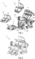
- the figure 1 illustrates an exploded view of the light module 1, while the picture 2 represents the light module 1 in which all the elements are assembled.
- the various elements of the light module 1 are described in detail below.
- the optical module 10 comprises a first reflector 100 provided with at least one light source.
- the additional optical module 40 comprises a second reflector 400 provided with at least one light source.
- the optical modules 10 and 40 include a plurality of light sources.
- the light sources are semiconductor emitter chips.
- a semiconductor emitter chip is part of a light-emitting diode.
- light-emitting diode we mean any type of light-emitting diode, whether in non-limiting examples LED (“Light Emitting Diode”), OLED (“organic LED”), AMOLED (Active-Matrix-Organic LED), or FOLED (Flexible OLED).
- LED Light Emitting Diode
- OLED organic LED
- AMOLED Active-Matrix-Organic LED
- FOLED Fluor
- Each optical module 10 and 40 further comprises at least one printed circuit board 305 and 405 respectively, also called PCB (“Printed Circuit Board”) to which the light sources are connected.
- PCB printed Circuit Board
- Each printed circuit board 305 and 405 is arranged respectively on the radiator 30 and 41 associated with each optical module 30 and 40.
- the first cut-off beam 101 and the second cut-off beam 401 are suitable for performing together a first photometric function f1 which is a dipped beam.
- the first cutoff beam 101 is a cutoff beam of which at least one portion is flat.
- the cutoff of the first cutoff beam 101 is an entirely flat upper cutoff
- the second cutoff beam 401 is a cutoff beam of which a portion is oblique.
- the first cutoff beam 101 is of the “flat” type
- the second cutoff beam is of the “kink” type.
- the cutoff of the second cutoff beam 401 is an entirely flat upper cutoff, and the first cutoff beam 101 is a cutoff beam of which a portion is oblique.
- the first cutoff beam 101 is of the “kink” type, while the second cutoff beam is of the “flat” type.
- the cutoff of the first cutoff beam 101 is an entirely flat upper cutoff, and the second cutoff beam 401 is also a flat cutoff beam.
- the first embodiment variant is illustrated in the picture 3 .
- the picture 3 illustrates a screen E disposed 25 meters from the light module 1 onto which the first and second cutoff beams 101 and 401 are projected.
- the first cutoff beam 101 comprises two flat portions 101a and 101b.
- the first cutoff beam 101 thus comprises an entirely flat upper cutoff.
- the second cutoff beam 401 comprises a portion 401a which is flat 401a and a portion 401b which is oblique.
- the two portions 101a and 101b of the cut-off beam are located at a distance d from a reference position P.
- the radiator 30-support plate 20 assembly will make it possible to position the first cut-off beam 101 produced by said optical module 10 at said reference position P.
- the assembly will make it possible to adjust the position of the first cut-off beam 101 so that the distance d is equal to 0.
- the position of the first beam will be able to be adjusted along the horizontal axis YY' illustrated on the picture 3 .
- the reference position P corresponds to a position in which a part 101a of the cutoff of the first beam is substantially superimposed on a part 401a of the cutoff of the second beam 401, in particular when the beams 101 and 401 are projected on the screen E placed 25m from the light module 1.
- the reference position P corresponds to a position in which a part 101a of the cutoff of the first beam is substantially superimposed on a part 401a of the cutoff of the second beam 401, in particular when the beams 101 and 401 are projected on the screen E placed 25m from the light module 1.
- the superimposition supports a tolerance of plus or minus 0.5° of the first beam with respect to the second beam.
- the reference position P corresponds to a horizontal part 401a of the second cut-off beam 400.
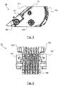
- the support plate 20 is illustrated on the figure 4a , 4b and 7 to 10 according to a non-limiting embodiment. On the figure 4 also illustrated is the radiator 30 which is positioned in the support plate 20.
- the support plate 20 comprises a first surface 200.
- This first surface 200 together with means for adjusting the radiator will make it possible to pivot the radiator 30 in rotation, so as to adjust the position of the first cut-off beam 101 to the reference position P described previously.
- the first surface 200 is cylindrical in shape with a circular directrix. This makes it possible to optimize the contact surface under the cooling fins 306 as illustrated on the figures 7 to 10 .
- the support plate 20 comprises two first surfaces 200.
- a slide 201 is provided with a rear stop.
- the opening makes it possible to have access to the first interface zone 302 (described later) after a manual rotation.
- the surface 202 has a U-shaped outline that forms the opening.
- the slide 201 is adapted to receive a male pivot pin 301 (described later) of the radiator 30. It will make it possible to block the radiator vertically and longitudinally at a given position and together with the male pin 301 to allow a rotation of the radiator 30 around an axis of rotation Ax passing through the center of said male pin 301.
- the slide assembly 201-male pin 301 thus forms a pivot connection.
- the screw barrel 204 is adapted to receive a fixing means 205 (described later) to lock the radiator 30 in position.
- the support plate 20 further comprises a second surface 203 facing the first surface 200, the two surfaces 200, 203 forming a guide groove for the rotation adjustment means 300 (described later ) of said radiator 30.
- the second surface 203 is cylindrical in shape with a circular directrix.
- the heater is shown on the figure 5 (side view) and 6 (rear side view).
- the shapes of the first surface 200 and of the adjustment means 300 are complementary to each other.
- the rotation adjustment means 300 are cylindrical in shape with a circular director as illustrated in the figure 5 .
- the rotation adjustment means 300 comprise two guide fins 300 of the radiator 30, in particular distributed on either side of the cooling fins 306.
- These guide fins 300 will come into contact with the first surface 200 and the support plate 20 and will make it possible to adjust the position of the first cut-off beam 101.
- These guide fins 300 also allow better heat dissipation from the radiator 30 because the air flow produced by a fan (not shown) coupled to the radiator 30 will cross said guide fins 300 vertically.
- At least one guide fin 300 of the radiator 30 is further adapted to receive a fixing means 205 (described later) inserted into the screw barrel 204 of said support plate 20.
- the radiator 30 comprises two guide fins 300 each adapted to receive a fixing means 205.
- the guide fins 300 each comprise an opening provided for this purpose.
- the rotation adjustment means 300 further comprise rear cooling fins 306 which have a cylindrical profile. This makes it possible to optimize the shape of the fins with respect to the available space.
- the radiator further comprises at least one additional interface zone 303 adapted to cooperate with an adjustment tool so as to actuate the rotation of the adjustment means 300 around the axis of rotation Ax.
- This interface zone 303 makes it possible, together with the first interface zone 302, to perform a fine rotation of the radiator 30 when it is in position in said support plate 20.
- the radiator 30 comprises two additional interface zones 303.
- the assembly of the elements of the light module 1 make it possible to position the first cut-off beam 101 of the “flat” type with respect to the second cut-off beam of the “kink” type.
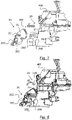
- the figure 7 illustrates the assembly of the radiator 30 on the support plate 20 according to a first assembly step.
- this first step is carried out by an operator manually.
- the radiator 30 only equipped with the PCB, that is to say without the optical module 10, is inserted into the support plate 20 in a horizontal direction as indicated by the arrow referenced a1.
- each male pivot pin 301 which is inserted into each slide 201 associated with the support plate 20.
- Each male pivot pin 301 thus slides along said slide 201 and reaches the end of its travel on the rear stop of said slide 201.
- the guide fins 300 come into contact with the first cylindrical surface 200 of the support plate 20 and due to their cylindrical shape (in the non-limiting embodiment illustrated), the surface of the guide fins 300 substantially conforms to the first surface cylindrical 200
- the first interface zone 302 is arranged, after the contact between the rotation adjustment means 300 of the radiator 30 and the first surface 200 of the support plate 20, at the level of the opening 202.
- the figure 8 illustrates the assembly of the radiator 30 on the support plate 20 according to a second assembly step.
- this second step is also carried out manually by an operator. According to this second step, the operator rotates the radiator 30 with his hand.
- the guide fins 300 pivot along the axis of rotation Ax which is an axis defined by the pivot connection formed by the slide assembly 201-male pivot pin.
- the arrow referenced a2 indicates the direction of rotation of the guide fins 300.
- the radiator 30 thus pivots until it reaches a so-called horizontal position.
- This pivoting makes it possible to adjust the radiator 30 and thus makes it possible to move the first cut-off beam 101 along a horizontal axis YY' (of the screen E illustrated on the picture 3 ) so that at least a part (here 101A) of said cut-off beam 101 reaches the reference position P.
- the figure 9 illustrates the assembly of the optical module 10 on the support plate 20 according to a third assembly step.
- this third step is also carried out manually by an operator.
- the operator assembles the optical module 10 here with its reflector 100 on the radiator 30.
- the arrow referenced a3 indicates the assembly direction which is perpendicular to the surface of the PCB.
- the printed circuit board 305 has been assembled beforehand, either on the radiator 30 at the location 307 which is dedicated to it, or on the optical module 10 itself.
- the figure 10 illustrates the assembly of the radiator 30 on the support plate 20 according to a fourth assembly step.
- this fourth step is carried out by means of a machine.
- This step makes it possible to fine-tune, by means of the first two interface zones 302, the position of the first cut-off beam 101 produced by the optical module 10 at the reference position P described above.
- the light sources of the two optical modules 101 and 401 are switched on so that they respectively produce the first cut-off beam 101 and the second cut-off beam 401.
- the switching on of the light sources is carried out successively so as to clearly observe the alignment of the cut-offs of the cut-off beams 101 and 401.
- the machine will be able to superimpose part 101a of the first cutoff beam 101 on part 401a of the second cutoff beam 401 according to the desired tolerance.
- the machine can also use the additional interface zones 303 described above to perform fine adjustment.
- the figures 11 to 13 illustrate the assembly of the radiator 30 on the support plate 20 according to a fifth assembly step.
- this fifth step is carried out by means of a machine.
- This step allows the radiator 30 to be clamped to the support plate 20.
- each fastening means 205 is inserted into the associated screw barrel 204 of the support plate 20 and into the dedicated opening of the associated guide fin 300 of the radiator 30.
- the fixing means 205 is a screw.
- the guide fins 300 are thus sandwiched between the cylindrical surfaces 200 and the fixing means 205, as illustrated in the top view figure 12 .
- the fixing means 205 apply a force so as to press the guide fins 300 against the cylindrical surfaces 200.
- the fixing means 205 are also illustrated on the rear view of the figure 13 .
- the radiator 30 is thus locked in position on the support plate 20 and thus no longer has any mechanical play.
- the assembly of the entire light module 1 is complete.
- the support plate 20 does not include a second surface 203.
- the cutoff of the first cutoff beam is a lower cutoff.
- the cutoff of the first cutoff beam is an entirely flat lower cutoff.
- the cutoff of the second cutoff beam is a lower cutoff.
- the cutoff of the second cutoff beam is an entirely flat lower cutoff.
- the first surface 200, the second surface 203 and the adjustment means 300 have a flat shape.
Landscapes
- Engineering & Computer Science (AREA)
- General Engineering & Computer Science (AREA)
- Physics & Mathematics (AREA)
- Microelectronics & Electronic Packaging (AREA)
- Optics & Photonics (AREA)
- Mathematical Physics (AREA)
- Non-Portable Lighting Devices Or Systems Thereof (AREA)
- Arrangement Of Elements, Cooling, Sealing, Or The Like Of Lighting Devices (AREA)
Claims (15)
- Leuchtmodul (1) für ein Kraftfahrzeug (V), das Folgendes beinhaltet:- mindestens ein optisches Modul (10), das dazu angepasst ist, ein erstes Bündel mit Abschattung (101) zu erzeugen;- eine Trägerplatte (20) für einen Kühlkörper (30);- einen Kühlkörper (30), der dazu angepasst ist, das optische Modul (10) aufzunehmen;- wobei die Trägerplatte (20) eine erste Fläche (200) beinhaltet;dadurch gekennzeichnet, dass- der Kühlkörper (30) Dreheinstellungsmittel (300) beinhaltet, die dazu angepasst sind:- mit der ersten Fläche (200) der Trägerplatte (20) in Kontakt zu kommen; und- um eine vorgegebene Drehachse (Ax) zu schwenken, um das erste Bündel mit Abschattung (101), das von dem optischen Modul (10) erzeugt wird, in einer Referenzposition (P) zu positionieren.
- Leuchtmodul (1) nach Anspruch 1, wobei das erste Bündel mit Abschattung (101) ein Bündel mit Abschattung ist, bei dem mindestens ein Abschnitt (101a) eben ist.
- Leuchtmodul (1) nach Anspruch 1 oder Anspruch 2, wobei die Dreheinstellungsmittel (300) zwei Rippen (300) zur Führung des Kühlkörpers (30) beinhalten, die sich insbesondere auf beiden Seiten der Kühlrippen (306) befinden.
- Leuchtmodul (1) nach Anspruch 3, wobei die erste Fläche (200) und die Dreheinstellungsmittel (300) eine zylindrische Form mit kreisförmiger Leitlinie aufweisen.
- Leuchtmodul (1) nach einem beliebigen der vorhergehenden Ansprüche 1 bis 4, wobei:- die Trägerplatte (20) ferner mindestens eine Gleitschiene (201) beinhaltet; und- der Kühlkörper (30) ferner einen Schwenkzapfen (301) beinhaltet, der dazu angepasst ist, in die Gleitschiene (201) der Trägerplatte (20) zu passen.
- Leuchtmodul (1) nach einem beliebigen der vorhergehenden Ansprüche 1 bis 5, wobei der Kühlkörper (30) ferner einen ersten Schnittstellenbereich (302) beinhaltet, der dazu angepasst ist, mit einem Einstellwerkzeug zusammenzuwirken, um die Drehung der Einstellungsmittel (300) um die Drehachse (Ax) zu bewirken.
- Leuchtmodul (1) nach dem vorhergehenden Anspruch 6, wobei:- die Trägerplatte (20) ferner eine Fläche beinhaltet, die über eine Öffnung (202) verfügt, die sich vor der ersten Fläche (200) befindet; und- der erste Schnittstellenbereich (302) nach dem Kontakt zwischen den Dreheinstellungsmitteln (300) des Kühlkörpers (30) und der ersten Fläche (200) der Trägerplatte (20) im Bereich der Öffnung angeordnet ist.
- Leuchtmodul (1) nach einem der Ansprüche 6 oder 7, wobei der Kühlkörper (30) ferner einen zusätzlichen Schnittstellenbereich (303) beinhaltet, der dazu angepasst ist, mit einem Einstellwerkzeug zusammenzuwirken, um die Drehung der Einstellungsmittel (300) um die Drehachse (Ax) zu bewirken.
- Leuchtmodul (1) nach einem beliebigen der vorhergehenden Ansprüche 1 bis 8, wobei:- die Trägerplatte (20) ferner eine Gewindehülse (204) beinhaltet; und- eine Führungsrippe (300) des Kühlkörpers (30) ferner dazu angepasst ist, ein Befestigungsmittel (205) aufzunehmen, das in die Gewindehülse (204) der Trägerplatte (20) eingepasst wird.
- Leuchtmodul (1) nach einem beliebigen der vorhergehenden Ansprüche 1 bis 9, wobei die Trägerplatte (20) ferner eine zweite Fläche (203) gegenüber der ersten Fläche (200) beinhaltet, wobei die zwei Flächen (200, 203) eine Führungsnut für die Dreheinstellungsmittel (300, 304) des Kühlkörpers (30) bilden.
- Leuchtmodul (1) nach einem beliebigen der vorhergehenden Ansprüche 1 bis 10, wobei die Trägerplatte (20) ferner dazu angepasst ist, ein zusätzliches optisches Modul (40) aufzunehmen, das dazu angepasst ist, ein zweites Bündel mit Abschattung (401) zu erzeugen.
- Leuchtmodul (1) nach dem vorhergehenden Anspruch 11, wobei das zweite Bündel mit Abschattung (401) ein Bündel mit Abschattung ist, bei dem ein Abschnitt schräg ist.
- Leuchtmodul (1) nach Anspruch 11 oder Anspruch 12, wobei die Referenzposition (P) einem horizontalen Teil (401a) des zweiten Bündels mit Abschattung (401) entspricht.
- Leuchtmodul (1) nach einem beliebigen der vorhergehenden Ansprüche 11 bis 13, wobei das erste Bündel mit Abschattung (101) und das zweite Bündel mit Abschattung (401) dazu angepasst sind, zusammen eine erste photometrische Funktion (f1), die ein Abblendlicht ist, umzusetzen.
- Beleuchtungsvorrichtung (2) für ein Kraftfahrzeug (V), die ein Leuchtmodul (1) nach einem beliebigen der vorhergehenden Ansprüche 1 bis 14 beinhaltet.
Applications Claiming Priority (1)
| Application Number | Priority Date | Filing Date | Title |
|---|---|---|---|
| FR1550515A FR3032023B1 (fr) | 2015-01-22 | 2015-01-22 | Module lumineux pour vehicule automobile |
Publications (2)
| Publication Number | Publication Date |
|---|---|
| EP3048359A1 EP3048359A1 (de) | 2016-07-27 |
| EP3048359B1 true EP3048359B1 (de) | 2022-09-14 |
Family
ID=52692942
Family Applications (1)
| Application Number | Title | Priority Date | Filing Date |
|---|---|---|---|
| EP16151615.8A Active EP3048359B1 (de) | 2015-01-22 | 2016-01-15 | Leuchtmodul für kraftfahrzeug |
Country Status (4)
| Country | Link |
|---|---|
| US (1) | US9822945B2 (de) |
| EP (1) | EP3048359B1 (de) |
| CN (1) | CN105823023B (de) |
| FR (1) | FR3032023B1 (de) |
Families Citing this family (8)
| Publication number | Priority date | Publication date | Assignee | Title |
|---|---|---|---|---|
| EP3354967B1 (de) * | 2017-01-31 | 2021-09-01 | Marelli Automotive Lighting Italy S.p.A. | Rotierendes beleuchtungsmodul mit willkommens-funktion und beleuchtungsvorrichtung für fahrzeuge |
| CN111237715B (zh) * | 2018-11-28 | 2023-08-15 | 法雷奥照明湖北技术中心有限公司 | 光学组件、照明和/或信号装置和车辆 |
| FR3100863A1 (fr) | 2019-09-12 | 2021-03-19 | Psa Automobiles Sa | Ensemble lumineux modulaire |
| US11046235B2 (en) | 2019-11-13 | 2021-06-29 | James M. Aparo | Vehicle headlight assembly having an ejectable and replaceable lightbulb |
| US11028989B2 (en) | 2019-11-13 | 2021-06-08 | James M. Aparo | Vehicle headlight device having an ejectable and replaceable lightbulb assembly |
| DE102022109084A1 (de) | 2022-04-13 | 2023-10-19 | Marelli Automotive Lighting Reutlingen (Germany) GmbH | Mechanische Verstellung von Hauptlichtmodulen auf fiktiven Drehachsen |
| FR3137743A1 (fr) * | 2022-07-11 | 2024-01-12 | Valeo Vision | Dissipateur thermique de module lumineux pour véhicule automobile et module lumineux pour véhicule automobile |
| FR3141505A1 (fr) * | 2022-10-28 | 2024-05-03 | Valeo Vision | Dispositif d'éclairage pour un véhicule automobile |
Family Cites Families (7)
| Publication number | Priority date | Publication date | Assignee | Title |
|---|---|---|---|---|
| DE102004062990A1 (de) * | 2004-12-22 | 2006-07-06 | Patent-Treuhand-Gesellschaft für elektrische Glühlampen mbH | Beleuchtungseinrichtung mit mindestens einer Leuchtdiode und Fahrzeugscheinwerfer |
| US8534888B2 (en) | 2010-09-10 | 2013-09-17 | Koito Manufacturing Co., Ltd. | Optical unit for a vehicular lamp |
| FR2980419B1 (fr) * | 2011-09-27 | 2014-05-09 | Valeo Vision | Module de projecteur de vehicule monte sur glissieres, support et projecteur correspondants |
| DE102012106313B4 (de) * | 2012-07-13 | 2022-06-09 | HELLA GmbH & Co. KGaA | Modulbaugruppe mit justierbaren Halbleiterlichtmodulen für einen Scheinwerfer und Verfahren zur Justierung |
| DE102012106314A1 (de) * | 2012-07-13 | 2014-01-16 | Hella Kgaa Hueck & Co. | Modulbaugruppe mit verschwenkbaren Halbleiterlichtmodulen für einenScheinwerfer |
| DE102012107432A1 (de) * | 2012-08-14 | 2014-05-15 | Hella Kgaa Hueck & Co. | Lichtsystem mit einer Kühlvorrichtung und einem optischen Körper |
| US9568160B2 (en) * | 2013-05-10 | 2017-02-14 | Grote Industries, Inc. | Lamp with a reflector |
-
2015
- 2015-01-22 FR FR1550515A patent/FR3032023B1/fr active Active
-
2016
- 2016-01-15 EP EP16151615.8A patent/EP3048359B1/de active Active
- 2016-01-20 US US15/001,897 patent/US9822945B2/en active Active
- 2016-01-22 CN CN201610045926.1A patent/CN105823023B/zh active Active
Also Published As
| Publication number | Publication date |
|---|---|
| CN105823023B (zh) | 2020-08-11 |
| US9822945B2 (en) | 2017-11-21 |
| US20160215951A1 (en) | 2016-07-28 |
| CN105823023A (zh) | 2016-08-03 |
| EP3048359A1 (de) | 2016-07-27 |
| FR3032023A1 (fr) | 2016-07-29 |
| FR3032023B1 (fr) | 2017-02-10 |
Similar Documents
| Publication | Publication Date | Title |
|---|---|---|
| EP3048359B1 (de) | Leuchtmodul für kraftfahrzeug | |
| CA2810385C (fr) | Module optique de dispositif d'eclairage et/ou de signalisation d'un vehicule automobile | |
| EP2574503B1 (de) | Scheinwerfermodul eines Kraftfahrzeugs mit Bajonettverschluss, Halterung und entsprechender Scheinwerfer | |
| EP2574501B1 (de) | Vorrichtung zur Beleuchtung und/oder Signalisierung für ein Fahrzeug | |
| EP3128230B1 (de) | Kühlkörper für optisches modul für kraftfahrzeug | |
| EP2598797B1 (de) | Optisches modul einer beleuchtungs- und/oder signalisierungsvorrichtung eines kraftfahrzeuges | |
| EP2394850B1 (de) | Gemeinsames manuell betätigbares Verstellsystem für zwei Beleuchtungsvorrichtungen, von denen eine automatisch verstellt werden kann | |
| FR2965039A1 (fr) | Module optique de dispositif d'eclairage et/ou de signalisation d'un vehicule automobile | |
| EP2888130A1 (de) | Beleuchtungsmodul mit einer an einem träger gehaltenen lösbaren vorrichtung | |
| EP3771861B1 (de) | Leuchtvorrichtung | |
| EP3290270B1 (de) | Leuchtvorrichtung für kraftfahrzeug | |
| EP2578451B1 (de) | Stellglied für Fahrzeugscheinwerfer | |
| EP3543597B1 (de) | Beleuchtungsmodul, das mit einer mikro-spiegel-matrix mit optimierter kühlung ausgestattet ist | |
| FR3055688A1 (fr) | Dispositif d'eclairage medical avec des leds orientees par des languettes predecoupees dans une carte de circuit imprime | |
| EP3251895B1 (de) | Vorrichtung zur beleuchtung und/oder signalisierung für kraftfahrzeug | |
| FR3004396A1 (fr) | Projecteur equipe de modules d'eclairage escamotables | |
| EP3141805B1 (de) | Beleuchtungssystem, insbesondere für kraftfahrzeug | |
| WO2020126823A1 (fr) | Procede d'assemblage d'un systeme optique de projecteur automobile et systeme optique de projecteur automobile associe | |
| EP2963335B1 (de) | Schwenkbare montage eines beleuchtungsmoduls für kraftfahrzeug | |
| EP3686478B1 (de) | Kompakte stirnlampe mit schwenkbarer platine | |
| EP3221185B1 (de) | Leuchteinheit für ein fahrzeug und dazugehöriges fahrzeug | |
| EP2842805B1 (de) | Leuchteneinheit mit Haltevorrichtung, die den Durchlass eines Luftstroms zu einem Heizkörper eines Kraftfahrzeugs erlaubt | |
| FR2987909A1 (fr) | Dispositif de projection d'image(s) holographique(s) a reglages multiples | |
| FR3091761A1 (fr) | Dispositif de combineur escamotable pour système d'affichage tête haute, système d'affichage tête haute comprenant un tel dispositif et véhicule équipé dudit système | |
| FR3099107A1 (fr) | Planche de bord agencee pour maintenir un appareil multimedia nomade dans un vehicule et vehicule correspondant |
Legal Events
| Date | Code | Title | Description |
|---|---|---|---|
| PUAI | Public reference made under article 153(3) epc to a published international application that has entered the european phase |
Free format text: ORIGINAL CODE: 0009012 |
|
| AK | Designated contracting states |
Kind code of ref document: A1 Designated state(s): AL AT BE BG CH CY CZ DE DK EE ES FI FR GB GR HR HU IE IS IT LI LT LU LV MC MK MT NL NO PL PT RO RS SE SI SK SM TR |
|
| AX | Request for extension of the european patent |
Extension state: BA ME |
|
| STAA | Information on the status of an ep patent application or granted ep patent |
Free format text: STATUS: REQUEST FOR EXAMINATION WAS MADE |
|
| 17P | Request for examination filed |
Effective date: 20161216 |
|
| RBV | Designated contracting states (corrected) |
Designated state(s): AL AT BE BG CH CY CZ DE DK EE ES FI FR GB GR HR HU IE IS IT LI LT LU LV MC MK MT NL NO PL PT RO RS SE SI SK SM TR |
|
| STAA | Information on the status of an ep patent application or granted ep patent |
Free format text: STATUS: EXAMINATION IS IN PROGRESS |
|
| 17Q | First examination report despatched |
Effective date: 20190926 |
|
| STAA | Information on the status of an ep patent application or granted ep patent |
Free format text: STATUS: EXAMINATION IS IN PROGRESS |
|
| REG | Reference to a national code |
Ref country code: DE Ref legal event code: R079 Ref document number: 602016074954 Country of ref document: DE Free format text: PREVIOUS MAIN CLASS: F21S0008100000 Ipc: F21S0041147000 |
|
| RIC1 | Information provided on ipc code assigned before grant |
Ipc: F21S 41/39 20180101ALI20220221BHEP Ipc: F21S 41/43 20180101ALI20220221BHEP Ipc: F21S 41/36 20180101ALI20220221BHEP Ipc: F21S 45/48 20180101ALI20220221BHEP Ipc: F21S 41/32 20180101ALI20220221BHEP Ipc: F21S 45/49 20180101ALI20220221BHEP Ipc: F21S 41/19 20180101ALI20220221BHEP Ipc: F21S 41/153 20180101ALI20220221BHEP Ipc: F21S 41/147 20180101AFI20220221BHEP |
|
| GRAP | Despatch of communication of intention to grant a patent |
Free format text: ORIGINAL CODE: EPIDOSNIGR1 |
|
| STAA | Information on the status of an ep patent application or granted ep patent |
Free format text: STATUS: GRANT OF PATENT IS INTENDED |
|
| INTG | Intention to grant announced |
Effective date: 20220401 |
|
| GRAS | Grant fee paid |
Free format text: ORIGINAL CODE: EPIDOSNIGR3 |
|
| GRAA | (expected) grant |
Free format text: ORIGINAL CODE: 0009210 |
|
| STAA | Information on the status of an ep patent application or granted ep patent |
Free format text: STATUS: THE PATENT HAS BEEN GRANTED |
|
| AK | Designated contracting states |
Kind code of ref document: B1 Designated state(s): AL AT BE BG CH CY CZ DE DK EE ES FI FR GB GR HR HU IE IS IT LI LT LU LV MC MK MT NL NO PL PT RO RS SE SI SK SM TR |
|
| REG | Reference to a national code |
Ref country code: GB Ref legal event code: FG4D Free format text: NOT ENGLISH |
|
| REG | Reference to a national code |
Ref country code: CH Ref legal event code: EP |
|
| REG | Reference to a national code |
Ref country code: DE Ref legal event code: R096 Ref document number: 602016074954 Country of ref document: DE |
|
| REG | Reference to a national code |
Ref country code: IE Ref legal event code: FG4D Free format text: LANGUAGE OF EP DOCUMENT: FRENCH |
|
| REG | Reference to a national code |
Ref country code: AT Ref legal event code: REF Ref document number: 1518898 Country of ref document: AT Kind code of ref document: T Effective date: 20221015 |
|
| REG | Reference to a national code |
Ref country code: LT Ref legal event code: MG9D |
|
| REG | Reference to a national code |
Ref country code: NL Ref legal event code: MP Effective date: 20220914 |
|
| PG25 | Lapsed in a contracting state [announced via postgrant information from national office to epo] |
Ref country code: SE Free format text: LAPSE BECAUSE OF FAILURE TO SUBMIT A TRANSLATION OF THE DESCRIPTION OR TO PAY THE FEE WITHIN THE PRESCRIBED TIME-LIMIT Effective date: 20220914 Ref country code: RS Free format text: LAPSE BECAUSE OF FAILURE TO SUBMIT A TRANSLATION OF THE DESCRIPTION OR TO PAY THE FEE WITHIN THE PRESCRIBED TIME-LIMIT Effective date: 20220914 Ref country code: NO Free format text: LAPSE BECAUSE OF FAILURE TO SUBMIT A TRANSLATION OF THE DESCRIPTION OR TO PAY THE FEE WITHIN THE PRESCRIBED TIME-LIMIT Effective date: 20221214 Ref country code: LV Free format text: LAPSE BECAUSE OF FAILURE TO SUBMIT A TRANSLATION OF THE DESCRIPTION OR TO PAY THE FEE WITHIN THE PRESCRIBED TIME-LIMIT Effective date: 20220914 Ref country code: LT Free format text: LAPSE BECAUSE OF FAILURE TO SUBMIT A TRANSLATION OF THE DESCRIPTION OR TO PAY THE FEE WITHIN THE PRESCRIBED TIME-LIMIT Effective date: 20220914 Ref country code: FI Free format text: LAPSE BECAUSE OF FAILURE TO SUBMIT A TRANSLATION OF THE DESCRIPTION OR TO PAY THE FEE WITHIN THE PRESCRIBED TIME-LIMIT Effective date: 20220914 |
|
| REG | Reference to a national code |
Ref country code: AT Ref legal event code: MK05 Ref document number: 1518898 Country of ref document: AT Kind code of ref document: T Effective date: 20220914 |
|
| PG25 | Lapsed in a contracting state [announced via postgrant information from national office to epo] |
Ref country code: HR Free format text: LAPSE BECAUSE OF FAILURE TO SUBMIT A TRANSLATION OF THE DESCRIPTION OR TO PAY THE FEE WITHIN THE PRESCRIBED TIME-LIMIT Effective date: 20220914 Ref country code: GR Free format text: LAPSE BECAUSE OF FAILURE TO SUBMIT A TRANSLATION OF THE DESCRIPTION OR TO PAY THE FEE WITHIN THE PRESCRIBED TIME-LIMIT Effective date: 20221215 |
|
| PG25 | Lapsed in a contracting state [announced via postgrant information from national office to epo] |
Ref country code: SM Free format text: LAPSE BECAUSE OF FAILURE TO SUBMIT A TRANSLATION OF THE DESCRIPTION OR TO PAY THE FEE WITHIN THE PRESCRIBED TIME-LIMIT Effective date: 20220914 Ref country code: RO Free format text: LAPSE BECAUSE OF FAILURE TO SUBMIT A TRANSLATION OF THE DESCRIPTION OR TO PAY THE FEE WITHIN THE PRESCRIBED TIME-LIMIT Effective date: 20220914 Ref country code: PT Free format text: LAPSE BECAUSE OF FAILURE TO SUBMIT A TRANSLATION OF THE DESCRIPTION OR TO PAY THE FEE WITHIN THE PRESCRIBED TIME-LIMIT Effective date: 20230116 Ref country code: ES Free format text: LAPSE BECAUSE OF FAILURE TO SUBMIT A TRANSLATION OF THE DESCRIPTION OR TO PAY THE FEE WITHIN THE PRESCRIBED TIME-LIMIT Effective date: 20220914 Ref country code: CZ Free format text: LAPSE BECAUSE OF FAILURE TO SUBMIT A TRANSLATION OF THE DESCRIPTION OR TO PAY THE FEE WITHIN THE PRESCRIBED TIME-LIMIT Effective date: 20220914 Ref country code: AT Free format text: LAPSE BECAUSE OF FAILURE TO SUBMIT A TRANSLATION OF THE DESCRIPTION OR TO PAY THE FEE WITHIN THE PRESCRIBED TIME-LIMIT Effective date: 20220914 |
|
| PGFP | Annual fee paid to national office [announced via postgrant information from national office to epo] |
Ref country code: FR Payment date: 20230125 Year of fee payment: 8 |
|
| PG25 | Lapsed in a contracting state [announced via postgrant information from national office to epo] |
Ref country code: SK Free format text: LAPSE BECAUSE OF FAILURE TO SUBMIT A TRANSLATION OF THE DESCRIPTION OR TO PAY THE FEE WITHIN THE PRESCRIBED TIME-LIMIT Effective date: 20220914 Ref country code: PL Free format text: LAPSE BECAUSE OF FAILURE TO SUBMIT A TRANSLATION OF THE DESCRIPTION OR TO PAY THE FEE WITHIN THE PRESCRIBED TIME-LIMIT Effective date: 20220914 Ref country code: IS Free format text: LAPSE BECAUSE OF FAILURE TO SUBMIT A TRANSLATION OF THE DESCRIPTION OR TO PAY THE FEE WITHIN THE PRESCRIBED TIME-LIMIT Effective date: 20230114 Ref country code: EE Free format text: LAPSE BECAUSE OF FAILURE TO SUBMIT A TRANSLATION OF THE DESCRIPTION OR TO PAY THE FEE WITHIN THE PRESCRIBED TIME-LIMIT Effective date: 20220914 |
|
| REG | Reference to a national code |
Ref country code: DE Ref legal event code: R097 Ref document number: 602016074954 Country of ref document: DE |
|
| PG25 | Lapsed in a contracting state [announced via postgrant information from national office to epo] |
Ref country code: NL Free format text: LAPSE BECAUSE OF FAILURE TO SUBMIT A TRANSLATION OF THE DESCRIPTION OR TO PAY THE FEE WITHIN THE PRESCRIBED TIME-LIMIT Effective date: 20220914 Ref country code: AL Free format text: LAPSE BECAUSE OF FAILURE TO SUBMIT A TRANSLATION OF THE DESCRIPTION OR TO PAY THE FEE WITHIN THE PRESCRIBED TIME-LIMIT Effective date: 20220914 |
|
| P01 | Opt-out of the competence of the unified patent court (upc) registered |
Effective date: 20230528 |
|
| PLBE | No opposition filed within time limit |
Free format text: ORIGINAL CODE: 0009261 |
|
| STAA | Information on the status of an ep patent application or granted ep patent |
Free format text: STATUS: NO OPPOSITION FILED WITHIN TIME LIMIT |
|
| PG25 | Lapsed in a contracting state [announced via postgrant information from national office to epo] |
Ref country code: DK Free format text: LAPSE BECAUSE OF FAILURE TO SUBMIT A TRANSLATION OF THE DESCRIPTION OR TO PAY THE FEE WITHIN THE PRESCRIBED TIME-LIMIT Effective date: 20220914 |
|
| 26N | No opposition filed |
Effective date: 20230615 |
|
| PG25 | Lapsed in a contracting state [announced via postgrant information from national office to epo] |
Ref country code: SI Free format text: LAPSE BECAUSE OF FAILURE TO SUBMIT A TRANSLATION OF THE DESCRIPTION OR TO PAY THE FEE WITHIN THE PRESCRIBED TIME-LIMIT Effective date: 20220914 |
|
| REG | Reference to a national code |
Ref country code: CH Ref legal event code: PL |
|
| GBPC | Gb: european patent ceased through non-payment of renewal fee |
Effective date: 20230115 |
|
| PG25 | Lapsed in a contracting state [announced via postgrant information from national office to epo] |
Ref country code: LU Free format text: LAPSE BECAUSE OF NON-PAYMENT OF DUE FEES Effective date: 20230115 |
|
| REG | Reference to a national code |
Ref country code: BE Ref legal event code: MM Effective date: 20230131 |
|
| PG25 | Lapsed in a contracting state [announced via postgrant information from national office to epo] |
Ref country code: LI Free format text: LAPSE BECAUSE OF NON-PAYMENT OF DUE FEES Effective date: 20230131 Ref country code: GB Free format text: LAPSE BECAUSE OF NON-PAYMENT OF DUE FEES Effective date: 20230115 Ref country code: CH Free format text: LAPSE BECAUSE OF NON-PAYMENT OF DUE FEES Effective date: 20230131 |
|
| PG25 | Lapsed in a contracting state [announced via postgrant information from national office to epo] |
Ref country code: BE Free format text: LAPSE BECAUSE OF NON-PAYMENT OF DUE FEES Effective date: 20230131 |
|
| PG25 | Lapsed in a contracting state [announced via postgrant information from national office to epo] |
Ref country code: IE Free format text: LAPSE BECAUSE OF NON-PAYMENT OF DUE FEES Effective date: 20230115 |
|
| PGFP | Annual fee paid to national office [announced via postgrant information from national office to epo] |
Ref country code: DE Payment date: 20240115 Year of fee payment: 9 |