EP3048312B1 - Verfahren zum herstellen einer profilverbindung - Google Patents
Verfahren zum herstellen einer profilverbindung Download PDFInfo
- Publication number
- EP3048312B1 EP3048312B1 EP16156144.4A EP16156144A EP3048312B1 EP 3048312 B1 EP3048312 B1 EP 3048312B1 EP 16156144 A EP16156144 A EP 16156144A EP 3048312 B1 EP3048312 B1 EP 3048312B1
- Authority
- EP
- European Patent Office
- Prior art keywords
- longitudinal
- longitudinal groove
- section
- connection screw
- profile bar
- Prior art date
- Legal status (The legal status is an assumption and is not a legal conclusion. Google has not performed a legal analysis and makes no representation as to the accuracy of the status listed.)
- Active
Links
Images

Classifications
-
- F—MECHANICAL ENGINEERING; LIGHTING; HEATING; WEAPONS; BLASTING
- F16—ENGINEERING ELEMENTS AND UNITS; GENERAL MEASURES FOR PRODUCING AND MAINTAINING EFFECTIVE FUNCTIONING OF MACHINES OR INSTALLATIONS; THERMAL INSULATION IN GENERAL
- F16B—DEVICES FOR FASTENING OR SECURING CONSTRUCTIONAL ELEMENTS OR MACHINE PARTS TOGETHER, e.g. NAILS, BOLTS, CIRCLIPS, CLAMPS, CLIPS OR WEDGES; JOINTS OR JOINTING
- F16B7/00—Connections of rods or tubes, e.g. of non-circular section, mutually, including resilient connections
- F16B7/18—Connections of rods or tubes, e.g. of non-circular section, mutually, including resilient connections using screw-thread elements
- F16B7/187—Connections of rods or tubes, e.g. of non-circular section, mutually, including resilient connections using screw-thread elements with sliding nuts or other additional connecting members for joining profiles provided with grooves or channels
Definitions
- connection screw having an external thread and an elongated profile bar, in particular an extruded profile of a light metal alloy, preferably of an aluminum alloy with at least one extending in the direction of the longitudinal extent of the profile bar, having a groove bottom, undercut longitudinal groove whose longitudinal groove longitudinal groove opening perpendicular to the longitudinal extension of the longitudinal groove (and perpendicular to Lcertainsnuthocherstreckung) of the groove bottom in the direction of a Lcertainsnuthocherstreckung is delimited by two spaced over the Llindsnutö Maschinen Publishing undercut sections, one perpendicular to the longitudinal extent of the longitudinal groove (and perpendicular to Lnaturesnuthocherstreckung) measured Lfitsnutö Maschinens dispose is less than a (measured in the same direction) maximum Lfitsnutbreite in one along the Lssensn uthocherstreckung be provided below the undercut portions located longitudinal groove area.
- Profile joints comprising a first and a second, respectively elongate profile bar made of a light metal alloy, usually an aluminum alloy, are well known.
- usually threaded sleeves are used with external thread, which are fixed in an undercut longitudinal groove of the profile bars and usually serve as a counterweight for a screw of a connector screw, the connector screw passes through a through hole of the threaded sleeve and with a screw thread (external thread) with a counter-bearing piece (sliding block) is screwed, wherein the sliding block is usually in the undercut longitudinal groove of the orthogonal to the longitudinal extent of the connector screw extending profile bar.
- a profile connection device in which a sliding block is clamped by turning a connector screw in an undercut longitudinal groove of a profile bar.
- the anchor bolt come with a front tip in contact with the groove bottom of the undercut longitudinal groove.
- the present invention seeks to provide a method for producing a profile connection, which has an increased robustness or strength, especially when force applied to the perpendicular to the longitudinal extension connector screw.
- the invention relates to a method for producing a profile connection.
- the profile connection to be produced by the method according to the invention is characterized in that the longitudinal channel forming the groove bottom of the longitudinal groove and the longitudinal channel extending parallel to the longitudinal groove spaced from the longitudinal groove, formed as a penetrating portion and / or Einform-section of the externally threaded connecting screw in the direction of the vertical extent of the associated undercut longitudinal groove penetrated, in particular punched, or formed the connecting screw in the direction of the high extent of the associated undercut longitudinal groove in the section is, such that the profiled bar material of the section is deformed into the longitudinal channel.
- the method is characterized by the steps of: providing a profiled bar formed according to the concept of the invention and a connector screw; Twisting the connector screw and thereby (due to the thread pitch of the connector screw outer thread) driving the connector screw into the penetrating portion, according to a first variant, the screwing of the connector screw is preferably carried out in a groove stone received in the undercut longitudinal groove of the profile bar, wherein by twisting and propelling the screw an opening for the screw is provided in the penetrating portion, in particular punched out, wherein the opening is preferably formed as a passage opening to the adjacent longitudinal channel.
- the connector screw does not penetrate the section (molding section) between the longitudinal groove and the longitudinal channel, but merely deforms or forms a depression in the section into the longitudinal channel.
- a pierced material is not removed or punched out, but remains connected to the adjacent profiled bar material of the (preforming) section.
- the invention is based on the idea of the elongated profile bar, which is preferably formed as an extruded profile of a light metal alloy, in particular of an aluminum alloy, in one Area with respect to the longitudinal hypertrophy (measured from the Lssensnutö réelle to the groove bottom) to be provided below the groove bottom with a longitudinal groove parallel to the longitudinal groove, wherein the groove bottom of the undercut longitudinal groove ausferender, closed, ie formed from a full profile profile material profile section is formed as a penetration section,
- the elongated profile bar which is preferably formed as an extruded profile of a light metal alloy, in particular of an aluminum alloy, in one Area with respect to the longitudinal hypertrophy (measured from the Lssensnutö réelle to the groove bottom) to be provided below the groove bottom with a longitudinal groove parallel to the longitudinal groove, wherein the groove bottom of the undercut longitudinal groove auslagender, closed, ie formed from a full profile profile material profile section is formed as a penetration section,
- the profile bar by means of a
- a longitudinal channel spaced from the side surface of the profile bar having the longitudinal slot opening, a longitudinal channel which penetrates or punctures the longitudinal channel spaced from the longitudinal groove Penetrating section by means of a connector screw, in particular when this is screwed with a groove located in the undercut longitudinal groove (abutment piece) for making a profile connection, wherein the connector screw in this screwing in the direction of the groove bottom of the longitudinal groove and through this into the fürdringungsabroughmaterial (profiled bar material) into it is screwed, wherein it is very particularly preferred if the penetration portion has a material thickness, the at least partially punching through the then preferably as a punching membrane au
- the penetration portion has a material thickness, the at least partially punching through the then preferably as a punching membrane au
- the material thickness of the penetrating portion is chosen so that a connector screw by introducing a torque by hand, ie not with an automated tool sufficient to bring into the longitudinal groove extending into the penetration into the penetration, in particular punching, ie break out.
- a profile connection made with a profile bar designed according to the concept of the invention is therefore characterized by increased strength and robustness.
- a penetration of the penetration section is understood to mean that by means of the connector screw an opening extending into the longitudinal groove can be produced in the penetration section by means of the connector screw, with the connector screw protruding into the thus prepared opening in the case of a finished profile connection, and this is particularly preferred penetrated into the longitudinal groove.
- the section designed as a solid material need not necessarily be penetrated by the connecting screw or be penetratable - Rather, it is sufficient if the groove bottom is formed by a single-form section made of profiled bar material or the longitudinal channel is spaced from the longitudinal groove by a profiled bar stock material formed from Einform section, in the manufacture of a positive connection with the profile bar a connector screw in the direction of L jossnuthocherstreckung (H) is einformbar, such that the profiled bar material of the Einform-section in the longitudinal channel is displaceable (einbulbar).
- the connecting screw is therefore not completely penetrated by the profile bar solid material portion between the longitudinal groove and the longitudinal channel, but merely formed in this. In this way, a positive connection can be produced, in contrast to the first alternative of the connecting screw no through opening in the aforementioned section is formed, but (only) a closed recess or indentation in the direction of L jossnuthocherstreckung.
- the invention has - regardless of the implementation form with Englishdringungs- and / or Einform-section also has the advantage that a profile connection produced with such a profile bar in a simple manner by unscrewing the at least one connector screw is again releasably, with a once dissolved profile connection simply again can be made by the connector screw is moved back into the original recess or through hole in the section between the longitudinal groove and the longitudinal channel.
- a facilitated finding the depression or through hole is, as will be explained later, by the realization of a front tapered connector screw possible - this can be realized, for example, in the front portion of the connector screw, a cone section.
- the connector screw is formed from a metal which is harder than the metal material of the profile bar. Most preferably, it is a steel screw, which is even more preferably made by cold extrusion.
- the connector screw may be hardened, for example by a tempering step.
- the profile connection fastener screw With regard to a favorable manufacturability of coming in the context of the profile connection fastener screw, it is preferred if it is formed in a front region of solid material, that has no frontal (front) recess.
- a front portion having a cylinder contour or in view of an improved or simplified retrieval of a recess or through hole already prepared a cone portion, wherein the cone simultaneously improved centering and optionally improved adhesive forces to improve the profile connection is ensured.
- the connector screw with front-side recess and ring cutting edge are also conceivable.
- the profile bar in which this not only a single combination of undercut longitudinal groove and arranged adjacent thereto longitudinal channel which is spaced over a trained as described above penetrating portion of the longitudinal groove, but if the profile bar on at least two sides has such combination, most preferably on all four sides, with two sides, in particular side surfaces of the profile bar are arranged at right angles to each other.
- the profile bar with a rectangular contour, wherein the corners of the rectangle are preferably not pointed but rounded.
- Particularly preferred is a square cross-sectional contour, in particular with rounded corners.
- the aforementioned material thickness is selected from a value range between 0.3 mm and 4 mm, very particularly preferably between 0.5 mm and 3 mm.
- Optimal seems to be a material thickness between 1 mm and 2mm, more preferably between 1.3mm and 1.8mm.
- the profile bar in which the profile bar has a central channel, i. a centrally arranged with respect to the end face of the profiled bar and extending in the direction of the longitudinal extension of the profiled bar channel which, for example according to a preferred embodiment has a circular cross-sectional contour, wherein also a jagged embodiment, i. an embodiment with in the circumferential direction next to each other and extending in the radial direction indentations or depressions is possible, as well as an embodiment with an annular or not jagged hollow cylindrical surface contour.
- a central channel i. a centrally arranged with respect to the end face of the profiled bar and extending in the direction of the longitudinal extension of the profiled bar channel which, for example according to a preferred embodiment has a circular cross-sectional contour, wherein also a jagged embodiment, i. an embodiment with in the circumferential direction next to each other and extending in the radial direction indentations or depressions is possible, as well as an embodiment with an annular or not jagged hollow cylindrical surface
- a height extension of the longitudinal channel selected in the direction of the longitudinal extension is greater than the height extent "material thickness" of the penetration section in this direction, in order to enable a removal or removal, preferably punched out or dissolved, solid material portion of the penetration portion, which in the manufacture of a Penetration opening in the penetrating portion by means of Connector screw results.
- the longitudinal channel has a rectangular cross-sectional contour (with a view of the front side) and / or that the cross-sectional contour of the longitudinal channel has a smaller extension in the direction of the longitudinal hypochrom extension than perpendicular thereto.
- the width of the longitudinal channel is greater than its height extent, wherein the longitudinal channel width preferably corresponds at least to the width of the L jossnutö réelle.
- the invention also leads to a profile connection with at least one formed according to the concept of the invention profile bar (first profile bar).
- the profile connection is characterized according to a first alternative in that in the penetration portion, an opening is provided which surrounds a connector screw, wherein preferably the connector screw protrudes into the adjacent longitudinal channel.
- the aforementioned opening or penetration opening is preferably made by means of the connector screw, wherein more preferably the opening is at least partially made by punching, ie breaking out a solid material portion by penetration portion, in particular by the connector screw is driven towards the penetrating portion by screwing with a sliding block.
- the connector screw preferably has a drive, for example a polygonal drive, in particular an Allen drive, or a Torx drive.
- the connector screw is formed only in the portion then serving as the Einform-section between the longitudinal groove and the longitudinal channel, such that material is dented into the longitudinal channel.
- a dent or connection is created by means of the connector screw in this case, which serves as a positive connection.
- connection screw it is therefore not absolutely necessary to penetrate the penetration section by means of the connection screw or to break or punch out material for producing a passage opening - for a simpler positive connection, it may be sufficient to deform the penetration section only by means of the connector screw in the manner of an injection section or by means of the connector screw to produce a recess, such that material of the penetration portion is molded or dented in the adjacent longitudinal channel.
- the connector screw is screwed with its external thread with a groove arranged in the longitudinal groove, which is penetrated by the connector screw in the direction of the vertical extent of the longitudinal groove.
- This sliding block preferably serves for fixing a connection of the first profiled bar to a further component, in particular a second profiled bar having an undercut longitudinal groove, which is even more preferred is designed according to the concept of the invention.
- another component for example a fastening angle or a hinge joint, may or may not be fixed to a first profiled bar in the manner described.
- the fixing component itself can not be used as the second profile rod from which to fixate Component be formed.
- a screw head of the connector screw can be indirectly or directly supported on the components to be fixed - a fixing sleeve, as is advantageous for fixing a second profile rod, need not be provided.
- the profile connection has a plurality of such connector screws, which can be screwed if necessary in each case with its own groove block in the longitudinal groove of the first profile bar, or with a common sliding block.
- a second profile bar is connected to the first profile bar, wherein the connector screw expediently arranged in an undercut longitudinal groove of the second profile bar fixing sleeve penetrated, wherein it is even more preferred if the connector screw rests with a screw head on a side facing away from the first profile bar front side of the sleeve.
- the component may be connected to the first profile bar via a plurality of parallel connector screws bolted to a common or separate groove stones, wherein preferably lateral connectors are positively connected to the penetration section and preferably penetrate them into the longitudinal channel.
- the connector screw can also only into the penetrating portion or alternatively be formed in an injection-molded section, so that in any case in the solid material section between the longitudinal groove and the longitudinal channel, a depression is formed and the solid material is deformed into the longitudinal channel.
- the connector screw in particular in the region of a front, i. End end has a cone portion for producing the positive connection with the penetration portion of the first profiled bar, wherein in the context of the profile connection, the connector screw is supported with the cone portion at the peripheral edge of an opening, preferably made with the connector screw opening in the penetrating portion. It has proven to be particularly advantageous with regard to the realization of a particularly strong connection when the cone section is designed as Morse cone, in particular with a cone angle (angle between the lateral surface of the cone and the longitudinal center axis of the screw of 1.26 ').
- the aforementioned cone angle is not more than 10 °, very particularly preferably a range of values between 0.5 ° and 10 ° is selected, most preferably between 1 ° and 5 °, even more preferably between 1 ° and 3 °.
- the cone section tapers in the direction of the front, i. in the screwing-in end of the connector screw.
- an additional inhibition against unscrewing the connector screw can be achieved.
- the connector screw has a flat end face at its front end in the insertion direction, ie not pointed, which is particularly easy a desired (not mandatory) punching effect can be achieved.
- the connector screw in the region of its front end a, preferably cylindrical opening which is circumferentially bounded by, in particular annular, Einformschn for facilitated molding in or penetrating the penetration portion.
- the Einformstoff are formed such that they mold into a certain depth when screwing the connector screw in the penetration portion, wherein it is possible according to a first alternative, that the Einformstoff mold on further screwing the connector screw until reaching the longitudinal channel and an extracted solid material of the penetration portion is received in the opening.
- the end opening in the connector screw can have a smaller depth extension than the material thickness of the penetration section measured in the direction of the longitudinal upward extension.
- the length of a screw shank of the connector screw measured from the lower edge of a screw head to the front end is equal to or smaller as the distance measured in the direction of the high extension of the longitudinal groove between the channel bottom and an abutment for the screw head, which is preferably formed by a (upper) peripheral edge of a fixing sleeve facing away from the first profiled bar, which is preferably received in a second profiled bar.
- the molding means are formed as a ring cutting edge, either with a straight cutting edge or with a structured, in particular corrugated or toothed cutting edge.
- the molding section with the largest part of its axial extent, in particular (also) in the region of the preferably provided circumferentially closed wall portion a smaller Has diameter than the external thread of the shaft, wherein preferably the outer diameter of the Einform section corresponds to the core diameter of the external thread.
- a simplification of the molding can also be achieved in that a radial cross section of the Einformprofils tapered in the axial direction forward, in particular blade-like, so as to increase the surface pressure in the region of the mold edge. If necessary, at least the front region of the molding means can be hardened.
- the connector screw in principle, it is possible for the connector screw to have a pin shape, i. is free of screws.
- the connector screw in particular in the context of a profile connection preferably together with a combination of a recorded in an undercut longitudinal groove of a first profiled bar nut block and anchored in the orthogonal profile arranged sleeve, which is then preferably designed as an internally threaded sleeve.
- the connector screw has a screw head with which it can be supported on an abutment in the context of the profile connection is very particularly preferred.
- This abutment can be formed by a fixing sleeve to be fixed in a second profiled bar, in particular to be fixed in an undercut longitudinal groove of the second profiled bar.
- the axial extent of the frontal opening is at least 3mm and in particular is selected from a range of values between 3mm and 5mm. Most preferably, the axial extent is at least 5% of the total axial extent of the connector screw.
- the abutment can be formed directly or indirectly from the component to be fastened, for example, an angle or a hinge.
- the connecting screw In addition or as an alternative to a second profiled bar, it is possible to connect a component different therefrom to the first profiled bar, for example a hinge or an angle.
- a component different therefrom to the first profiled bar, for example a hinge or an angle.
- the connecting screw penetrates the then formed as a penetrating portion portion between the longitudinal groove and the longitudinal channel and according to an alternative embodiment only as an insert section formed or serving as a molding section forming section and deforms material of the Einform-section into the longitudinal channel section into or dent.
- a second, in particular according to the concept of the invention trained profile bar is connected to the first profile bar via the method described above, in which case the connector screw preferably arranged in the second profile bar, more precisely an undercut longitudinal groove of the second profile bar or fixed sleeve interspersed and screwed with a male in the first longitudinal groove of the first profile bar groove block in the manner described above and thereby with the front end of the connector screw, a through hole is made in the penetrating portion to the longitudinal channel, wherein it is particularly useful in the finished connector screw, the connector screw with its outer circumference, in particular the outer circumference of an optional cone section is supported on the edge side in the opening of the penetration section.
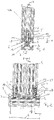
- a profile connection 1 comprising an elongated (first) profile bar 2, which is formed in the embodiment shown as an extruded profile of an aluminum alloy. Furthermore, the profile connection 1 comprises a component 3, which is likewise designed as a profile bar 2 (second profile bar), which is oriented perpendicular to the first profile bar 2.
- the profiled bar 2 and the component 3 are fixed to one another by means of a connecting screw 4 having a screw head 5 by way of example here.
- the section 7 can be formed as a penetration section, which can be penetrated by a connector screw, in particular punched through, in order thus to create a passage opening between the longitudinal groove and the longitudinal channel.
- a connector screw With only a comparatively slight tightening of the connector screw, it is possible not to pierce or penetrate the penetrating portion, but merely to mold in such a way that a depression is formed and material of the portion is dented or molded into the longitudinal channel.
- section 7 not to interpret section 7 from the outset as a penetrating section, but only as an insert section, which allows molding of a connector screw in the direction of the longitudinal extent of the longitudinal groove, such that a dent in the molding section or recess for the realization of the positive connection results and material of the Einform section is formed or dented into the longitudinal channel.
- a connector screw 4 (the profile connection 1 contains two such connector screws 4 by way of example) passes through an opening 10 introduced into the penetration section 7 by means of the connector screw 4 and projects into the longitudinal channel 9. Laterally, the connector screw 4 is supported on the peripheral edge the opening 10, so that perpendicular to the longitudinal extent of the component 3 oriented forces can be optimally absorbed.
- the (first) profile bar 2 as viewed in the cross-sectional view four identical side surfaces, wherein the cross-sectional contour is square.
- Each side surface is in each case assigned an identically formed combination of undercut longitudinal groove 6 and a longitudinal channel 9 which is spaced apart here by way of example as a penetration section 7.
- the profiled bar 2 has a central channel 11, from which the longitudinal channel 9 is spaced over a solid material section 12 in the direction of the vertical extent H of the undercut longitudinal groove 6.
- a Loughsnutö réelle 13 of the undercut longitudinal groove is bounded by two opposing undercuts 14, 15 which define the width b of the Lzansnutö réelle 13.
- a maximum longitudinal groove width b n is achieved in a region below the undercuts 14, 15.
- the maximum longitudinal groove width b n and the longitudinal groove height extension H oriented perpendicular thereto are oriented perpendicular to the longitudinal extent L (cf. Fig. 2 the elongated profile bar 2).
- each connector screw 4 passes through a sleeve 16 and is supported with its screw head 5 on the side facing away from the first profile bar 2 side on the sleeve 16.
- the sleeve 16 is received, for example by means of an external thread or other, for example, bayonet-like fixing in an undercut longitudinal groove 6 of the component 3.
- the connector screw 4 passes through each of the perpendicular to the longitudinal extent L of the section bar 2 oriented sleeve 16 and is with its external thread 17 with the internal thread 18 of a sliding block 19 (abutment piece) screwed, which is received in the undercut longitudinal groove 6.
- the sliding block 19 is in the assembled state (see. Fig. 2 right) penetrated by the connector screw 4, which also protrudes into the section 7 and this preferably, as shown, also in the longitudinal channel 9 passes through.
- FIG. 6 A possible embodiment of the connector screw 4 is in Fig. 6 shown. This optionally comprises a screw head 5.
- an opening 20 here a blind hole opening is provided, which is surrounded by molding means 21, here in the form of a uniform annular cutting edge, the end of a circumferentially closed peripheral wall 22 is arranged.
- molding means 21 here in the form of a uniform annular cutting edge
- a flat front end i. an end without opening 20 or with an opening 20 may be provided with a smaller axial extent.
- Fig. 6 is a the front end opposite or facing away from this drive 23 is not shown. This is for example in Fig. 2 to recognize.
- Fig. 3 shows a section of a finished connection or the detail Fig. 1 which is the right connector screw connection according to Fig. 2 equivalent.
- This sleeve 16 is formed internal thread-free.
- the screw head 5 of the connector screw 4 is supported on the front side of the sleeve 16, wherein the connector screw 4 is screwed with its external thread 17 with a sliding block 19 in the undercut longitudinal groove 6.
- the connector screw 4 passes through the Lssensnutö réelle 13.
- the connector screw 4 passes through the sliding block 19 in the direction of the upward extension H of the undercut longitudinal groove 6 and passes through an opening 20 made in the section 7 through the longitudinal channel 9 by means of the connector screw 4.
- the section 7 is formed as a punchable punching diaphragm. This has in the embodiment shown, a material thickness M of about 1.5 mm.
- the waste piece 24 (pinhole) resulting from the introduction of the opening 20 may be referred to as punching waste because the opening 20 is made in a lower portion of the opening by punching out the waste piece 24.
- the waste piece 24 is located within the longitudinal channel 9, in which the connector screw 4 protrudes. It can be seen that the distance between the central channel 11 and the longitudinal channel 9 is greater than the material thickness M of the penetration section 7. However, this is not mandatory.
- the width of the extension of a rectangular cross-sectional contour longitudinal channel 9 corresponds approximately to the width b of L jossnutö réelle 13.
- Fig. 7 shows in a longitudinal sectional view of an upper half of a first profiled bar, wherein a connector screw 4 is shown very schematically, the analogous to Fig. 3 may be fixed in a further component, in particular a second profiled bar.
- the connector screw passes through a sliding block 9 in the undercut longitudinal groove 6.
- the connector screw 4 dellt the section 7 in the direction of the high extension H of the longitudinal groove 6 in the longitudinal channel 9 into it.
- Fig. 4 shows the situation left in Fig. 2 in an enlarged detail.
- the connector screw 4 is not yet finally mounted but is still on the formed as a penetration section section 7, which is formed as a punched punching membrane, on.
- the connector screw 4 already passes through a sleeve 16 received in an undercut longitudinal groove 6 of the component 3 (second profile rod) in the direction of the upward extension H of the undercut longitudinal groove 6 of the first profiled bar 2 and is screwed to the sliding block 19 in the interior of the undercut longitudinal channel 6 and passes through it Region, so that a front end of the connector screw 4, which is here exemplified with Einformatorial) is applied to the penetration portion 7.
- Einformffenn 21 optionalal
Landscapes
- Engineering & Computer Science (AREA)
- General Engineering & Computer Science (AREA)
- Mechanical Engineering (AREA)
- Mutual Connection Of Rods And Tubes (AREA)
- Body Structure For Vehicles (AREA)
- Shafts, Cranks, Connecting Bars, And Related Bearings (AREA)
- Extrusion Of Metal (AREA)
Priority Applications (1)
| Application Number | Priority Date | Filing Date | Title |
|---|---|---|---|
| PL16156144T PL3048312T3 (pl) | 2014-09-22 | 2015-07-24 | Sposób wytwarzania połączenia profili |
Applications Claiming Priority (2)
| Application Number | Priority Date | Filing Date | Title |
|---|---|---|---|
| DE202014104524.4U DE202014104524U1 (de) | 2014-09-22 | 2014-09-22 | Profilstab sowie Profilverbindung |
| EP15750647.8A EP3039302B1 (de) | 2014-09-22 | 2015-07-24 | Profilstab sowie profilverbindung |
Related Parent Applications (2)
| Application Number | Title | Priority Date | Filing Date |
|---|---|---|---|
| EP15750647.8A Division-Into EP3039302B1 (de) | 2014-09-22 | 2015-07-24 | Profilstab sowie profilverbindung |
| EP15750647.8A Division EP3039302B1 (de) | 2014-09-22 | 2015-07-24 | Profilstab sowie profilverbindung |
Publications (2)
| Publication Number | Publication Date |
|---|---|
| EP3048312A1 EP3048312A1 (de) | 2016-07-27 |
| EP3048312B1 true EP3048312B1 (de) | 2017-09-27 |
Family
ID=53872009
Family Applications (2)
| Application Number | Title | Priority Date | Filing Date |
|---|---|---|---|
| EP16156144.4A Active EP3048312B1 (de) | 2014-09-22 | 2015-07-24 | Verfahren zum herstellen einer profilverbindung |
| EP15750647.8A Active EP3039302B1 (de) | 2014-09-22 | 2015-07-24 | Profilstab sowie profilverbindung |
Family Applications After (1)
| Application Number | Title | Priority Date | Filing Date |
|---|---|---|---|
| EP15750647.8A Active EP3039302B1 (de) | 2014-09-22 | 2015-07-24 | Profilstab sowie profilverbindung |
Country Status (7)
| Country | Link |
|---|---|
| US (1) | US20170241459A1 (pl) |
| EP (2) | EP3048312B1 (pl) |
| DE (1) | DE202014104524U1 (pl) |
| EA (1) | EA034042B1 (pl) |
| ES (1) | ES2653805T3 (pl) |
| PL (2) | PL3039302T3 (pl) |
| WO (1) | WO2016045822A1 (pl) |
Families Citing this family (6)
| Publication number | Priority date | Publication date | Assignee | Title |
|---|---|---|---|---|
| DE202016004724U1 (de) | 2016-08-03 | 2017-11-06 | Isel Facility GmbH | Verbindungsvorrichtung |
| KR102070423B1 (ko) * | 2018-09-07 | 2020-01-28 | 김용래 | 프로파일 연결장치 |
| IT201900000127A1 (it) * | 2019-01-07 | 2020-07-07 | Cerloj Ema | Profilo estruso |
| DE102020200390A1 (de) * | 2020-01-14 | 2021-07-15 | Wolfgang Rixen | Widerlagerhülse |
| US11629495B2 (en) | 2020-09-18 | 2023-04-18 | Wei-Jan Lin | Modular framing structure design and a method of using the same |
| CN115320730B (zh) * | 2022-08-23 | 2024-03-26 | 奇瑞汽车股份有限公司 | 一种型材螺纹套筒连接结构 |
Family Cites Families (17)
| Publication number | Priority date | Publication date | Assignee | Title |
|---|---|---|---|---|
| US4775259A (en) * | 1986-11-04 | 1988-10-04 | Benada Aluminum Of Florida, Inc. | Connector arrangement |
| PL159155B1 (pl) * | 1989-06-14 | 1992-11-30 | Wkret do drewna samogwintujacy PL | |
| DE4016320C1 (pl) | 1990-05-21 | 1991-09-19 | Wolfgang Dipl.-Ing. Rixen | |
| FR2692010B1 (fr) * | 1992-06-03 | 1996-02-09 | Adl Automation | Bloc de liaison et d'assemblage pour barres profilees et assemblage de barres en faisant application. |
| DE4329044C2 (de) * | 1993-08-28 | 1997-08-14 | Heron Sondermaschinen Und Steu | Klemmkörper mit Verstiftelement |
| US5414967A (en) * | 1993-10-19 | 1995-05-16 | Unistrut International Corp. | Clean room wall system |
| US5806897A (en) * | 1995-10-03 | 1998-09-15 | Smc Corporation | Mechanism for attaching a fluid-related device to a device-attaching frame member |
| JP4045561B2 (ja) * | 1997-10-21 | 2008-02-13 | Smc株式会社 | 機器取付用フレーム部材に対する流体圧部材の取付機構 |
| US6209275B1 (en) * | 1998-07-20 | 2001-04-03 | Southland Industries | Cleanroom wall system |
| DE20210133U1 (de) * | 2002-07-01 | 2003-11-13 | Bosch Rexroth AG, 70173 Stuttgart | Verbindung von Profilstreben |
| US6802171B2 (en) * | 2002-10-18 | 2004-10-12 | Mckinnon Duane | Framing member with fastener attachments having square threads |
| DE20302751U1 (de) * | 2003-02-19 | 2003-04-30 | FMS Förder- und Montage-Systeme Schmalzhofer GmbH, 75031 Eppingen | Profilverbindungseinrichtung |
| US20060078371A1 (en) * | 2004-01-22 | 2006-04-13 | Holscher Winfried K W | Joining device for two bar-type hollow profiled members, and method for the production thereof |
| DE502004002170D1 (de) | 2004-03-11 | 2007-01-11 | Richard Band | Profilverbindung |
| JP5435211B2 (ja) * | 2009-04-08 | 2014-03-05 | コスモンド株式会社 | ユニットルームとその二段設置構造 |
| DE202011003315U1 (de) * | 2011-02-28 | 2012-05-30 | I-Dimod Gmbh & Co. Kg | Verbindungsvorrichtung |
| US10619791B2 (en) * | 2013-03-14 | 2020-04-14 | Eaton Intelligent Power Limited | Channel framing with additional functional side |
-
2014
- 2014-09-22 DE DE202014104524.4U patent/DE202014104524U1/de not_active Expired - Lifetime
-
2015
- 2015-07-24 WO PCT/EP2015/067077 patent/WO2016045822A1/de not_active Ceased
- 2015-07-24 PL PL15750647T patent/PL3039302T3/pl unknown
- 2015-07-24 PL PL16156144T patent/PL3048312T3/pl unknown
- 2015-07-24 US US15/512,972 patent/US20170241459A1/en not_active Abandoned
- 2015-07-24 EP EP16156144.4A patent/EP3048312B1/de active Active
- 2015-07-24 EA EA201790656A patent/EA034042B1/ru not_active IP Right Cessation
- 2015-07-24 ES ES16156144.4T patent/ES2653805T3/es active Active
- 2015-07-24 EP EP15750647.8A patent/EP3039302B1/de active Active
Non-Patent Citations (1)
| Title |
|---|
| None * |
Also Published As
| Publication number | Publication date |
|---|---|
| EA034042B1 (ru) | 2019-12-20 |
| EP3039302A1 (de) | 2016-07-06 |
| DE202014104524U1 (de) | 2016-01-05 |
| ES2653805T3 (es) | 2018-02-08 |
| PL3039302T3 (pl) | 2017-09-29 |
| WO2016045822A1 (de) | 2016-03-31 |
| EP3048312A1 (de) | 2016-07-27 |
| US20170241459A1 (en) | 2017-08-24 |
| EA201790656A1 (ru) | 2017-07-31 |
| PL3048312T3 (pl) | 2018-05-30 |
| EP3039302B1 (de) | 2017-03-22 |
Similar Documents
| Publication | Publication Date | Title |
|---|---|---|
| EP2549128B1 (de) | Funktionselement mit Verdrehsicherungsmerkmalen sowie Zusammenbauteil bestehend aus dem Funktionselement und einem Blechteil | |
| EP3039302B1 (de) | Profilstab sowie profilverbindung | |
| EP1674741B1 (de) | Ein durch Nieten an ein Blechteil anbringbares Element sowie Zusammenbauteil und Verfahren zur Erzeugung des Zusammenbauteils | |
| EP2809497B1 (de) | Expansionskopf für aufweitwerkzeuge und diesen umfassendes expansionswerkzeug | |
| EP3719330B1 (de) | Schraube mit diskontinuität an zwischengewindeabschnitt | |
| WO2000009833A1 (de) | Befestigungsvorrichtung für stäbe, pfosten, masten oder dgl. im erdreich und verfahren zur herstellung einer befestigungsvorrichtung | |
| EP0993902A2 (de) | Verfahren zur Anbringung eines Funktionselementes, Matrize, Funktionselement, Zusammenbauteil | |
| EP1918596A1 (de) | Blindnietelement sowie Verwendung hierfür | |
| EP2229538A1 (de) | Befestigungselement | |
| EP1725355B1 (de) | Verfahren zur herstellung von hohlkörperelementen, hohlkörperelement sowie folgeverbundwerkzeug | |
| EP2224143B1 (de) | Mutter, Schraubverbindung, Profilverbindung sowie Verfahren zum Herstellen einer Mutter | |
| EP2232087B1 (de) | Verbindungseinrichtung und verfahren zum erstellen einer schraubverbindung | |
| EP3374649B1 (de) | Gewindeformende schraube | |
| DE102008053346A1 (de) | Abstandselement für die Anbringung an einem Blechteil, Zusammenbauteil und Verfahren zu dessen Herstellung | |
| DE102012108779A1 (de) | Profilverbindung | |
| EP3047159B1 (de) | Profilverbinder sowie profilverbund | |
| EP2609342B1 (de) | Befestigungselement | |
| DE20312075U1 (de) | Vorrichtung mit zwei durch eine Verbindungsschraube zusammengehaltenen Hohlprofilen sowie Werkzeug dazu | |
| DE102007046788B3 (de) | Verfahren zum Herstellen eines Schließringbolzens und Schließringbolzen | |
| EP3667106A1 (de) | Funktionselement, zusammenbauteil und verfahren zur herstellung des zusammenbauteils | |
| DE102006046631B4 (de) | Verschlussschraube mit Ringnut sowie Herstellungsverfahren | |
| DE4445806C1 (de) | Loch- und gewindeformende Schraube sowie Verfahren zum Eindrehen derselben | |
| DE102019110635A1 (de) | Zusammenbauteil bestehend aus einem Bauteil und einem Element mit einem Kopfteil und einem auf einer Seite des Kopfteils angeordneten Kragen sowie Herstellungsverfahren | |
| EP3564545A1 (de) | Zusammenbauteil bestehend aus einem bauteil und einem element mit einem kopfteil und einem auf einer seite des kopfteils angeordneten kragen sowie herstellungsverfahren | |
| EP2261518B1 (de) | Loch- und gewindeformende Schraube |
Legal Events
| Date | Code | Title | Description |
|---|---|---|---|
| PUAI | Public reference made under article 153(3) epc to a published international application that has entered the european phase |
Free format text: ORIGINAL CODE: 0009012 |
|
| AC | Divisional application: reference to earlier application |
Ref document number: 3039302 Country of ref document: EP Kind code of ref document: P |
|
| AK | Designated contracting states |
Kind code of ref document: A1 Designated state(s): AL AT BE BG CH CY CZ DE DK EE ES FI FR GB GR HR HU IE IS IT LI LT LU LV MC MK MT NL NO PL PT RO RS SE SI SK SM TR |
|
| AX | Request for extension of the european patent |
Extension state: BA ME |
|
| 17P | Request for examination filed |
Effective date: 20170118 |
|
| RBV | Designated contracting states (corrected) |
Designated state(s): AL AT BE BG CH CY CZ DE DK EE ES FI FR GB GR HR HU IE IS IT LI LT LU LV MC MK MT NL NO PL PT RO RS SE SI SK SM TR |
|
| GRAP | Despatch of communication of intention to grant a patent |
Free format text: ORIGINAL CODE: EPIDOSNIGR1 |
|
| INTG | Intention to grant announced |
Effective date: 20170421 |
|
| GRAS | Grant fee paid |
Free format text: ORIGINAL CODE: EPIDOSNIGR3 |
|
| GRAA | (expected) grant |
Free format text: ORIGINAL CODE: 0009210 |
|
| AC | Divisional application: reference to earlier application |
Ref document number: 3039302 Country of ref document: EP Kind code of ref document: P |
|
| AK | Designated contracting states |
Kind code of ref document: B1 Designated state(s): AL AT BE BG CH CY CZ DE DK EE ES FI FR GB GR HR HU IE IS IT LI LT LU LV MC MK MT NL NO PL PT RO RS SE SI SK SM TR |
|
| REG | Reference to a national code |
Ref country code: GB Ref legal event code: FG4D Free format text: NOT ENGLISH |
|
| REG | Reference to a national code |
Ref country code: CH Ref legal event code: EP |
|
| REG | Reference to a national code |
Ref country code: AT Ref legal event code: REF Ref document number: 932245 Country of ref document: AT Kind code of ref document: T Effective date: 20171015 |
|
| REG | Reference to a national code |
Ref country code: IE Ref legal event code: FG4D Free format text: LANGUAGE OF EP DOCUMENT: GERMAN |
|
| REG | Reference to a national code |
Ref country code: DE Ref legal event code: R096 Ref document number: 502015001986 Country of ref document: DE |
|
| REG | Reference to a national code |
Ref country code: CH Ref legal event code: NV Representative=s name: BODENSEEPATENT PATENTANWAELTE BEHRMANN WAGNER , CH |
|
| PG25 | Lapsed in a contracting state [announced via postgrant information from national office to epo] |
Ref country code: HR Free format text: LAPSE BECAUSE OF FAILURE TO SUBMIT A TRANSLATION OF THE DESCRIPTION OR TO PAY THE FEE WITHIN THE PRESCRIBED TIME-LIMIT Effective date: 20170927 Ref country code: SE Free format text: LAPSE BECAUSE OF FAILURE TO SUBMIT A TRANSLATION OF THE DESCRIPTION OR TO PAY THE FEE WITHIN THE PRESCRIBED TIME-LIMIT Effective date: 20170927 Ref country code: LT Free format text: LAPSE BECAUSE OF FAILURE TO SUBMIT A TRANSLATION OF THE DESCRIPTION OR TO PAY THE FEE WITHIN THE PRESCRIBED TIME-LIMIT Effective date: 20170927 Ref country code: FI Free format text: LAPSE BECAUSE OF FAILURE TO SUBMIT A TRANSLATION OF THE DESCRIPTION OR TO PAY THE FEE WITHIN THE PRESCRIBED TIME-LIMIT Effective date: 20170927 Ref country code: NO Free format text: LAPSE BECAUSE OF FAILURE TO SUBMIT A TRANSLATION OF THE DESCRIPTION OR TO PAY THE FEE WITHIN THE PRESCRIBED TIME-LIMIT Effective date: 20171227 |
|
| REG | Reference to a national code |
Ref country code: NL Ref legal event code: MP Effective date: 20170927 |
|
| REG | Reference to a national code |
Ref country code: ES Ref legal event code: FG2A Ref document number: 2653805 Country of ref document: ES Kind code of ref document: T3 Effective date: 20180208 |
|
| REG | Reference to a national code |
Ref country code: LT Ref legal event code: MG4D |
|
| PG25 | Lapsed in a contracting state [announced via postgrant information from national office to epo] |
Ref country code: GR Free format text: LAPSE BECAUSE OF FAILURE TO SUBMIT A TRANSLATION OF THE DESCRIPTION OR TO PAY THE FEE WITHIN THE PRESCRIBED TIME-LIMIT Effective date: 20171228 Ref country code: RS Free format text: LAPSE BECAUSE OF FAILURE TO SUBMIT A TRANSLATION OF THE DESCRIPTION OR TO PAY THE FEE WITHIN THE PRESCRIBED TIME-LIMIT Effective date: 20170927 Ref country code: LV Free format text: LAPSE BECAUSE OF FAILURE TO SUBMIT A TRANSLATION OF THE DESCRIPTION OR TO PAY THE FEE WITHIN THE PRESCRIBED TIME-LIMIT Effective date: 20170927 Ref country code: BG Free format text: LAPSE BECAUSE OF FAILURE TO SUBMIT A TRANSLATION OF THE DESCRIPTION OR TO PAY THE FEE WITHIN THE PRESCRIBED TIME-LIMIT Effective date: 20171227 |
|
| PG25 | Lapsed in a contracting state [announced via postgrant information from national office to epo] |
Ref country code: NL Free format text: LAPSE BECAUSE OF FAILURE TO SUBMIT A TRANSLATION OF THE DESCRIPTION OR TO PAY THE FEE WITHIN THE PRESCRIBED TIME-LIMIT Effective date: 20170927 |
|
| PG25 | Lapsed in a contracting state [announced via postgrant information from national office to epo] |
Ref country code: RO Free format text: LAPSE BECAUSE OF FAILURE TO SUBMIT A TRANSLATION OF THE DESCRIPTION OR TO PAY THE FEE WITHIN THE PRESCRIBED TIME-LIMIT Effective date: 20170927 |
|
| PG25 | Lapsed in a contracting state [announced via postgrant information from national office to epo] |
Ref country code: SM Free format text: LAPSE BECAUSE OF FAILURE TO SUBMIT A TRANSLATION OF THE DESCRIPTION OR TO PAY THE FEE WITHIN THE PRESCRIBED TIME-LIMIT Effective date: 20170927 Ref country code: IS Free format text: LAPSE BECAUSE OF FAILURE TO SUBMIT A TRANSLATION OF THE DESCRIPTION OR TO PAY THE FEE WITHIN THE PRESCRIBED TIME-LIMIT Effective date: 20180127 Ref country code: SK Free format text: LAPSE BECAUSE OF FAILURE TO SUBMIT A TRANSLATION OF THE DESCRIPTION OR TO PAY THE FEE WITHIN THE PRESCRIBED TIME-LIMIT Effective date: 20170927 Ref country code: EE Free format text: LAPSE BECAUSE OF FAILURE TO SUBMIT A TRANSLATION OF THE DESCRIPTION OR TO PAY THE FEE WITHIN THE PRESCRIBED TIME-LIMIT Effective date: 20170927 |
|
| REG | Reference to a national code |
Ref country code: DE Ref legal event code: R097 Ref document number: 502015001986 Country of ref document: DE |
|
| REG | Reference to a national code |
Ref country code: FR Ref legal event code: PLFP Year of fee payment: 4 |
|
| PG25 | Lapsed in a contracting state [announced via postgrant information from national office to epo] |
Ref country code: DK Free format text: LAPSE BECAUSE OF FAILURE TO SUBMIT A TRANSLATION OF THE DESCRIPTION OR TO PAY THE FEE WITHIN THE PRESCRIBED TIME-LIMIT Effective date: 20170927 |
|
| PLBE | No opposition filed within time limit |
Free format text: ORIGINAL CODE: 0009261 |
|
| STAA | Information on the status of an ep patent application or granted ep patent |
Free format text: STATUS: NO OPPOSITION FILED WITHIN TIME LIMIT |
|
| 26N | No opposition filed |
Effective date: 20180628 |
|
| PG25 | Lapsed in a contracting state [announced via postgrant information from national office to epo] |
Ref country code: MT Free format text: LAPSE BECAUSE OF FAILURE TO SUBMIT A TRANSLATION OF THE DESCRIPTION OR TO PAY THE FEE WITHIN THE PRESCRIBED TIME-LIMIT Effective date: 20170927 |
|
| PG25 | Lapsed in a contracting state [announced via postgrant information from national office to epo] |
Ref country code: SI Free format text: LAPSE BECAUSE OF FAILURE TO SUBMIT A TRANSLATION OF THE DESCRIPTION OR TO PAY THE FEE WITHIN THE PRESCRIBED TIME-LIMIT Effective date: 20170927 |
|
| PG25 | Lapsed in a contracting state [announced via postgrant information from national office to epo] |
Ref country code: LU Free format text: LAPSE BECAUSE OF NON-PAYMENT OF DUE FEES Effective date: 20180724 Ref country code: MC Free format text: LAPSE BECAUSE OF FAILURE TO SUBMIT A TRANSLATION OF THE DESCRIPTION OR TO PAY THE FEE WITHIN THE PRESCRIBED TIME-LIMIT Effective date: 20170927 |
|
| REG | Reference to a national code |
Ref country code: BE Ref legal event code: MM Effective date: 20180731 |
|
| REG | Reference to a national code |
Ref country code: IE Ref legal event code: MM4A |
|
| PG25 | Lapsed in a contracting state [announced via postgrant information from national office to epo] |
Ref country code: IE Free format text: LAPSE BECAUSE OF NON-PAYMENT OF DUE FEES Effective date: 20180724 |
|
| PG25 | Lapsed in a contracting state [announced via postgrant information from national office to epo] |
Ref country code: BE Free format text: LAPSE BECAUSE OF NON-PAYMENT OF DUE FEES Effective date: 20180731 |
|
| PG25 | Lapsed in a contracting state [announced via postgrant information from national office to epo] |
Ref country code: TR Free format text: LAPSE BECAUSE OF FAILURE TO SUBMIT A TRANSLATION OF THE DESCRIPTION OR TO PAY THE FEE WITHIN THE PRESCRIBED TIME-LIMIT Effective date: 20170927 |
|
| PG25 | Lapsed in a contracting state [announced via postgrant information from national office to epo] |
Ref country code: PT Free format text: LAPSE BECAUSE OF FAILURE TO SUBMIT A TRANSLATION OF THE DESCRIPTION OR TO PAY THE FEE WITHIN THE PRESCRIBED TIME-LIMIT Effective date: 20170927 |
|
| PG25 | Lapsed in a contracting state [announced via postgrant information from national office to epo] |
Ref country code: MK Free format text: LAPSE BECAUSE OF NON-PAYMENT OF DUE FEES Effective date: 20170927 Ref country code: HU Free format text: LAPSE BECAUSE OF FAILURE TO SUBMIT A TRANSLATION OF THE DESCRIPTION OR TO PAY THE FEE WITHIN THE PRESCRIBED TIME-LIMIT; INVALID AB INITIO Effective date: 20150724 Ref country code: CY Free format text: LAPSE BECAUSE OF FAILURE TO SUBMIT A TRANSLATION OF THE DESCRIPTION OR TO PAY THE FEE WITHIN THE PRESCRIBED TIME-LIMIT Effective date: 20170927 |
|
| PG25 | Lapsed in a contracting state [announced via postgrant information from national office to epo] |
Ref country code: AL Free format text: LAPSE BECAUSE OF FAILURE TO SUBMIT A TRANSLATION OF THE DESCRIPTION OR TO PAY THE FEE WITHIN THE PRESCRIBED TIME-LIMIT Effective date: 20170927 |
|
| REG | Reference to a national code |
Ref country code: CH Ref legal event code: PFA Owner name: FLAIG, HARTMUT, DE Free format text: FORMER OWNER: FLAIG, HARTMUT, DE |
|
| PGFP | Annual fee paid to national office [announced via postgrant information from national office to epo] |
Ref country code: ES Payment date: 20250819 Year of fee payment: 11 |
|
| PGFP | Annual fee paid to national office [announced via postgrant information from national office to epo] |
Ref country code: DE Payment date: 20250730 Year of fee payment: 11 |
|
| PGFP | Annual fee paid to national office [announced via postgrant information from national office to epo] |
Ref country code: PL Payment date: 20250716 Year of fee payment: 11 Ref country code: IT Payment date: 20250731 Year of fee payment: 11 |
|
| PGFP | Annual fee paid to national office [announced via postgrant information from national office to epo] |
Ref country code: GB Payment date: 20250724 Year of fee payment: 11 |
|
| PGFP | Annual fee paid to national office [announced via postgrant information from national office to epo] |
Ref country code: AT Payment date: 20250721 Year of fee payment: 11 Ref country code: FR Payment date: 20250723 Year of fee payment: 11 |
|
| PGFP | Annual fee paid to national office [announced via postgrant information from national office to epo] |
Ref country code: CH Payment date: 20250801 Year of fee payment: 11 |
|
| PGFP | Annual fee paid to national office [announced via postgrant information from national office to epo] |
Ref country code: CZ Payment date: 20250711 Year of fee payment: 11 |