EP3048311A1 - Connecteurs de serrage - Google Patents
Connecteurs de serrage Download PDFInfo
- Publication number
- EP3048311A1 EP3048311A1 EP15152015.2A EP15152015A EP3048311A1 EP 3048311 A1 EP3048311 A1 EP 3048311A1 EP 15152015 A EP15152015 A EP 15152015A EP 3048311 A1 EP3048311 A1 EP 3048311A1
- Authority
- EP
- European Patent Office
- Prior art keywords
- housing
- clamping
- transmission member
- connector according
- recess
- Prior art date
- Legal status (The legal status is an assumption and is not a legal conclusion. Google has not performed a legal analysis and makes no representation as to the accuracy of the status listed.)
- Granted
Links
- 239000011230 binding agent Substances 0.000 title 1
- 230000005540 biological transmission Effects 0.000 claims abstract description 32
- 210000002105 tongue Anatomy 0.000 claims description 18
- IHQKEDIOMGYHEB-UHFFFAOYSA-M sodium dimethylarsinate Chemical class [Na+].C[As](C)([O-])=O IHQKEDIOMGYHEB-UHFFFAOYSA-M 0.000 claims description 4
- 238000004873 anchoring Methods 0.000 abstract description 3
- 108010089746 wobe Proteins 0.000 abstract 1
- 238000003892 spreading Methods 0.000 description 4
- 238000010276 construction Methods 0.000 description 2
- 238000004519 manufacturing process Methods 0.000 description 2
- 101100008047 Caenorhabditis elegans cut-3 gene Proteins 0.000 description 1
- 238000005452 bending Methods 0.000 description 1
- 230000006835 compression Effects 0.000 description 1
- 238000007906 compression Methods 0.000 description 1
- 210000003746 feather Anatomy 0.000 description 1
- 238000003780 insertion Methods 0.000 description 1
- 230000037431 insertion Effects 0.000 description 1
- 238000003754 machining Methods 0.000 description 1
- 238000003801 milling Methods 0.000 description 1
- 238000003825 pressing Methods 0.000 description 1
Images


Classifications
-
- F—MECHANICAL ENGINEERING; LIGHTING; HEATING; WEAPONS; BLASTING
- F16—ENGINEERING ELEMENTS AND UNITS; GENERAL MEASURES FOR PRODUCING AND MAINTAINING EFFECTIVE FUNCTIONING OF MACHINES OR INSTALLATIONS; THERMAL INSULATION IN GENERAL
- F16B—DEVICES FOR FASTENING OR SECURING CONSTRUCTIONAL ELEMENTS OR MACHINE PARTS TOGETHER, e.g. NAILS, BOLTS, CIRCLIPS, CLAMPS, CLIPS OR WEDGES; JOINTS OR JOINTING
- F16B5/00—Joining sheets or plates, e.g. panels, to one another or to strips or bars parallel to them
- F16B5/0004—Joining sheets, plates or panels in abutting relationship
- F16B5/0084—Joining sheets, plates or panels in abutting relationship characterised by particular locking means
- F16B5/0092—Joining sheets, plates or panels in abutting relationship characterised by particular locking means with locking means rotating about an axis parallel to the main plane and perpendicular to the abutting edge, e.g. screw, bayonet
-
- F—MECHANICAL ENGINEERING; LIGHTING; HEATING; WEAPONS; BLASTING
- F16—ENGINEERING ELEMENTS AND UNITS; GENERAL MEASURES FOR PRODUCING AND MAINTAINING EFFECTIVE FUNCTIONING OF MACHINES OR INSTALLATIONS; THERMAL INSULATION IN GENERAL
- F16B—DEVICES FOR FASTENING OR SECURING CONSTRUCTIONAL ELEMENTS OR MACHINE PARTS TOGETHER, e.g. NAILS, BOLTS, CIRCLIPS, CLAMPS, CLIPS OR WEDGES; JOINTS OR JOINTING
- F16B2/00—Friction-grip releasable fastenings
- F16B2/02—Clamps, i.e. with gripping action effected by positive means other than the inherent resistance to deformation of the material of the fastening
- F16B2/04—Clamps, i.e. with gripping action effected by positive means other than the inherent resistance to deformation of the material of the fastening internal, i.e. with spreading action
-
- F—MECHANICAL ENGINEERING; LIGHTING; HEATING; WEAPONS; BLASTING
- F16—ENGINEERING ELEMENTS AND UNITS; GENERAL MEASURES FOR PRODUCING AND MAINTAINING EFFECTIVE FUNCTIONING OF MACHINES OR INSTALLATIONS; THERMAL INSULATION IN GENERAL
- F16B—DEVICES FOR FASTENING OR SECURING CONSTRUCTIONAL ELEMENTS OR MACHINE PARTS TOGETHER, e.g. NAILS, BOLTS, CIRCLIPS, CLAMPS, CLIPS OR WEDGES; JOINTS OR JOINTING
- F16B2/00—Friction-grip releasable fastenings
- F16B2/02—Clamps, i.e. with gripping action effected by positive means other than the inherent resistance to deformation of the material of the fastening
- F16B2/06—Clamps, i.e. with gripping action effected by positive means other than the inherent resistance to deformation of the material of the fastening external, i.e. with contracting action
- F16B2/10—Clamps, i.e. with gripping action effected by positive means other than the inherent resistance to deformation of the material of the fastening external, i.e. with contracting action using pivoting jaws
-
- F—MECHANICAL ENGINEERING; LIGHTING; HEATING; WEAPONS; BLASTING
- F16—ENGINEERING ELEMENTS AND UNITS; GENERAL MEASURES FOR PRODUCING AND MAINTAINING EFFECTIVE FUNCTIONING OF MACHINES OR INSTALLATIONS; THERMAL INSULATION IN GENERAL
- F16B—DEVICES FOR FASTENING OR SECURING CONSTRUCTIONAL ELEMENTS OR MACHINE PARTS TOGETHER, e.g. NAILS, BOLTS, CIRCLIPS, CLAMPS, CLIPS OR WEDGES; JOINTS OR JOINTING
- F16B2/00—Friction-grip releasable fastenings
- F16B2/02—Clamps, i.e. with gripping action effected by positive means other than the inherent resistance to deformation of the material of the fastening
- F16B2/14—Clamps, i.e. with gripping action effected by positive means other than the inherent resistance to deformation of the material of the fastening using wedges
-
- F—MECHANICAL ENGINEERING; LIGHTING; HEATING; WEAPONS; BLASTING
- F16—ENGINEERING ELEMENTS AND UNITS; GENERAL MEASURES FOR PRODUCING AND MAINTAINING EFFECTIVE FUNCTIONING OF MACHINES OR INSTALLATIONS; THERMAL INSULATION IN GENERAL
- F16B—DEVICES FOR FASTENING OR SECURING CONSTRUCTIONAL ELEMENTS OR MACHINE PARTS TOGETHER, e.g. NAILS, BOLTS, CIRCLIPS, CLAMPS, CLIPS OR WEDGES; JOINTS OR JOINTING
- F16B7/00—Connections of rods or tubes, e.g. of non-circular section, mutually, including resilient connections
- F16B7/04—Clamping or clipping connections
- F16B7/044—Clamping or clipping connections for rods or tubes being in angled relationship
- F16B7/0446—Clamping or clipping connections for rods or tubes being in angled relationship for tubes using the innerside thereof
- F16B7/0453—Clamping or clipping connections for rods or tubes being in angled relationship for tubes using the innerside thereof the tubes being drawn towards each other
- F16B7/046—Clamping or clipping connections for rods or tubes being in angled relationship for tubes using the innerside thereof the tubes being drawn towards each other by rotating an eccenter-mechanism
-
- F—MECHANICAL ENGINEERING; LIGHTING; HEATING; WEAPONS; BLASTING
- F16—ENGINEERING ELEMENTS AND UNITS; GENERAL MEASURES FOR PRODUCING AND MAINTAINING EFFECTIVE FUNCTIONING OF MACHINES OR INSTALLATIONS; THERMAL INSULATION IN GENERAL
- F16B—DEVICES FOR FASTENING OR SECURING CONSTRUCTIONAL ELEMENTS OR MACHINE PARTS TOGETHER, e.g. NAILS, BOLTS, CIRCLIPS, CLAMPS, CLIPS OR WEDGES; JOINTS OR JOINTING
- F16B7/00—Connections of rods or tubes, e.g. of non-circular section, mutually, including resilient connections
- F16B7/04—Clamping or clipping connections
- F16B7/044—Clamping or clipping connections for rods or tubes being in angled relationship
- F16B7/0446—Clamping or clipping connections for rods or tubes being in angled relationship for tubes using the innerside thereof
- F16B7/0473—Clamping or clipping connections for rods or tubes being in angled relationship for tubes using the innerside thereof with hook-like parts gripping, e.g. by expanding, behind the flanges of a profile
Definitions
- the invention relates to a clamping connector for releasably connecting two elements, of which the first has an undercut longitudinal groove and the second a receiving space for a housing of the clamping connector, wherein the housing of the clamping connector two opposite each other in the longitudinal direction of the housing end faces and at least one of the two end sides connecting side wall, with a bearing member mounted in the transmission member, wherein the transmission member by means of an actuating element in the longitudinal direction of the housing between a clamping position and a mounting position is movable, wherein the transmission member drives an anchor element for arrangement in an undercut longitudinal groove, which anchor element both in the clamping position protrudes in the mounting position on one of the end sides of the housing in the longitudinal direction, wherein the transmission member is partially retracted in the clamping position in the housing and as a result there s transmission member and the anchor member are deflected by a arranged in the movement path ramp mechanism transversely to the longitudinal direction of the housing.
- Such clamp connectors are known from the prior art. These are devices for connecting two or more profile elements together. Such profile elements and clamp connectors are used for the rapid construction and / or dismantling of exhibition stands, shelving systems and the like.
- wallboard panels for the mobile construction of walls.
- These comprise a flat wallboard, which on all four edges with a total of one Frame forming profile elements is occupied.
- the individual profile elements are connected in the corner regions of the frame by means of generic clamp connectors.
- the clamping connector is inserted into a first element such as a profile element.
- the element has a receiving space for the housing of the clamping connector.
- a second element with an undercut longitudinal groove for example, a corresponding profile element, on the front side of the housing of the terminal connector projecting anchor elements inserted.
- the anchor elements are transferred into the clamping position, the anchor elements in this configuration clasping the undercut longitudinal groove from the rear.
- the two (profile) elements are then securely connected.
- a generic clamp connector is from the EP 1 234 985 B1 known.
- an adapter element is proposed which is first introduced into the element providing the receiving space. Only then is the actual clamping connector with its housing plugged into this adapter.
- the known compression connectors have proven to be fundamentally good.
- the use of the adapter entails that different adapters must be maintained for different receiving spaces.
- the assembly must be carried out in two stages, as initially the adapter is introduced into the receiving space and only then the actual terminal connector can be mounted. In this respect, it is in the prior art even with only minor deviations of the geometry of the receiving space required to use different adapters and / or different terminal connector.
- a recess is formed, wherein a jaw of the transmission member, In particular leaf spring element projects in the clamping position through the recess through the side wall of the housing.
- the clou of the invention is that not only leads to a clamping or spreading movement of the front side of the housing projecting anchor elements by pressing the transmission member, in particular leaf spring element from the mounting position into the clamping position, but also a spreading movement in the region of the housing itself ,
- the spreading movement is due to the fact that the clamping jaw protrudes through the recess in the housing over the side wall of the housing. In other words, the thickness or height of the housing is increased by the jaw. It takes place in the clamping position, a spreading in a region of the housing, which is inserted when used properly in the element with the receiving space for the housing.
- the anchoring elements engage behind the undercut groove and thus secure the first element with the undercut groove.
- the jaw extends through the recess through out of the housing and thus ensures that the clamp connector is also clamped to the second element.
- the housing is firmly clamped in the receiving space of the second element.
- a possible clearance between the housing on the one hand and the receiving space in the second element on the other hand can be compensated for by the jaw protruding from the housing when transferred to the clamping position.
- the transmission member is used to implement an exclusively rotating movement of the actuating element in an at least translational movement of the anchor element and according to the invention also the jaw.
- the transmission member may preferably be formed as a leaf spring element. If in the following the leaf spring element is mentioned, this also applies to the more generally understood transmission element, unless it depends in particular on the resilient properties of the leaf spring element.
- the anchor element may be an integral part of the transmission element or leaf spring element.
- the jaw is a device for forming a frictional connection with a wall defining the recess.
- the jaw may have a friction-increasing surface, for example in the form of a friction lining.
- the clamping jaw is arranged between the anchor element and an armature element opposite end of the leaf spring element.
- the jaw is located with respect to the longitudinal direction of the housing both in the assembled position and in the clamping position in the interior of the housing.
- the jaw and the anchor element thus serve to clamp the terminal connector with different parts.
- the clamping connector has substantially the same geometric shape as the clamping connector known from the prior art described at the beginning.
- an inventive clamp connector is downwardly compatible and can be used very flexible. It is advantageous in this case if the jaw is formed elastically bendable. In a receiving space, which allows no leakage of the jaw out of the recess, the jaw can avoid this type of forced operation under elastic deflection.
- the jaw may be formed by a curved portion of the leaf spring element.
- the jaw may be polygonal or continuously curved. It can be a convex shape.
- the jaw can be the same material thickness as have the remaining leaf spring element. In this respect, the jaw can be easily introduced into a main body of the leaf spring element by, for example, bending.
- the recess opens into a longitudinal edge limiting the housing in the longitudinal direction.
- the recess may be formed by an attached at the front edge and U-shaped section.
- the recess is formed exclusively in a two narrow sides of the housing interconnecting broad side. The two narrow sides, however, still extend to the front edge of the housing. As a result, a good stability of the housing is achieved, so that the functionality of a clamping connector according to the invention is not deteriorated compared to the prior art.
- the recess may be introduced material abtragend in the housing.
- the recess can be introduced, for example, by a machining process such as milling in the housing.
- the manufacture of the housing can be made very flexible and at will, which simplifies the manufacture of the terminal connector and also reduces the associated costs.
- the width of the recess may correspond to the width of the leaf spring element. This also includes those embodiments in which the width of the recess has a slight oversize relative to the width of the leaf spring element. It is crucial in this context that the recess can be made relatively narrow, which increases the stability of the housing.
- the leaf spring element has two tongues separated by a cut in the longitudinal direction. Both tongues may each have an anchoring element at their front ends protruding from the housing.
- the two tongues can be mirror-inverted. Both tongues may have a jaw.
- the operation of the terminal connector from the mounting position into the clamping position causes both the anchor elements of the two tongues are spread apart and thus ensure a secure fit in the undercut longitudinal groove, and the two jaws of the tongues are spread apart in the opposite direction , As a result, the clamping connector is thus held particularly securely on both elements while at the same time conceivably simple assembly.
- the housing has two recesses, wherein in each case a recess is formed on one of the broad sides, wherein the recesses are spaced apart in the width direction.
- the recesses extend on each broad side of the housing only slightly less than half of the broad side, which ensures good stability of the housing.
- the leaf spring element is mounted on a web extending in the width direction through the housing, wherein the clamping jaw and the web together form the ramp mechanism.
- One or both of these parts are ramped.
- Ramp-shaped means that the part has a contact surface with an inclination to the longitudinal direction of the housing in the transverse direction. A movement of the leaf spring element in the longitudinal direction in the housing is thus at least partially converted by the ramp mechanism into a movement in the transverse direction.
- the leaf spring element In the mounting position, the leaf spring element can surround the web with the rear side of the clamping jaw.
- the back of the jaw is the side opposite to an outside of the jaw for contact with the interior of the receiving space.
- the back of the jaw is directed towards the interior of the housing of the clamp connector. It can be provided that the leaf spring element is relaxed in the mounting position. In the clamping position, however, the leaf spring element is pushed with the back of the jaw under deflection of the leaf spring element on the web.
- the jaw is formed starting from a base body of the leaf spring element higher than the anchor element.
- the clamping connector can also be arranged in receiving spaces whose thickness is greater than the thickness of the undercut of the undercut longitudinal groove for the anchor elements.
- the jaw projects at least 1 mm, preferably 2 mm, through the recess over the side wall of the housing.
- the clamping connector can also be mounted in such recesses, whose thickness is significantly shorter than the thickness of the terminal connector housing itself.
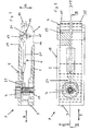
- FIG. 1 shows a first embodiment of a clamp connector 1.
- This has a housing 2.
- the housing 2 is formed substantially cuboid. It has two broad sides, one of which is called side wall 5. The two broad sides are connected by narrow sides 18.
- the housing 2 is finally limited by opposing end faces 3, 4.
- a transmission member 6 is arranged in the form of a leaf spring element (hereinafter, the reference numeral 6 is used for the leaf spring element).
- the leaf spring element 6 in the present case has two tongues, which are separated from each other by a section in the longitudinal direction 8. Both tongues of the leaf spring element 6 have at their front side protruding from the housing 2 ends in each case an anchor element 10, 11.
- an actuating element 7 is arranged in the housing 2. This serves to switch the leaf spring element 6 between a clamping position and a mounting position.
- a recess 13 is introduced frontally.
- the recess 13 is approximately as wide as one of the tongues of the leaf spring element 6.
- clamp connector 1 The function of the clamp connector 1 will be described below generally with reference to FIGS FIGS. 1 to 5 unless expressly stated otherwise.
- the arranged inside the housing 2 leaf spring element 6 is integrally formed. It has a common part which is in operative connection with the actuating element 7.
- an opening 27 is introduced.
- the opening 27 is circular, but a circular segment is not formed as an opening.
- the actuating element 7 is inserted.
- the actuator 7 is connected via an eccentric 23 with the opening 27 limiting side wall in contact. By a rotation of the actuating element 7, the eccentric 23 slides on the side wall of the opening 27, wherein the leaf spring element 6 characterized between the in the FIGS. 2 and 3 shown assembly position and in the FIGS. 4 and 5 shown clamping position can be moved back and forth.
- a second part of the leaf spring element 6 is, as already mentioned, divided by a section in the longitudinal direction 8 in the two tongues.
- Each tongue has a main body 21, at whose end-side end the anchor element 10, 11 is arranged.
- a jaw 17 is also formed in the main body 21, a jaw 17 is also formed. In the present case, this is designed as a polygonal bulge.
- the clamping jaw 17 is arranged below the recess 13. With its rear side, the clamping jaw 17 encloses a web 14.
- the web 14 extends in the width direction 9 through the housing 2 therethrough. It is mounted in the two narrow sides 18 of the housing 2.
- another web 15 is provided. It is also conceivable that the two webs 14, 15 are formed as an integral part.
- the jaw 17 Due to the polygonal course, the jaw 17 has a ramp 20 on its rear side.
- the ramp 20 extends obliquely with respect to the longitudinal direction 8 of the housing, namely bevelled in the transverse direction 12 or height direction. If now the leaf spring element is moved by rotating the actuating element 7 in the direction of the clamping position, slides and / or rolls the jaw 17 with its ramp 20 on the web 14 from. The movement of the leaf spring element 6 in the longitudinal direction 8 is thereby deflected according to the slope of the ramp 20 in the transverse direction 12. As a result, the leaf spring member 6 is elastically deflected in the transverse direction 12. It finally reaches the in FIG. 5 shown location.
- clamping jaw 17 now projects beyond the outer surface of the side wall 5 out of the housing 2.
- the jaw 17 would be in the in FIG. 5 shown position against the wall of a receptacle for the housing 2 press.
- the clamping connector 1 would be clamped in the receptacle.
- the anchor element 10 is deflected. It engages in the in FIG. 5
- the clamping connector 1 thus ensures overall that the two elements 22, 28 are securely connected to each other, by clamping with the aid of the jaw 17 relative to the second element 28 on the one hand and by engaging behind the groove in the first element 22 by means of the anchor member 10 on the other.
- a receptacle for the head of the actuating element 7 is provided in the recording providing element 28 . This is not shown.
- the insertion of the terminal connector 1 in the receptacle in the element 28 is as follows from equip.
- the actuator 7 is in the in FIG. 3 turned assembly position shown.
- the actuating element 7 is supported by a spring 29 in the housing 2. It can be pressed against the force of the spring 29 in the housing 2, so that the head of the actuating element 7 no longer projects from the side wall 5.
- the clamp connector 1 is inserted into the receptacle in the element 28. Reached the clamp connector 1 its intended position, the actuating element 7 fast by the force of the spring 29 in the corresponding receptacle provided for the actuator 7 high.
- the clamping connector 1 is then held in a form-fitting manner with respect to its longitudinal direction 8 in the receptacle in the element 28 in a first step.
- the first element 22 is attached to the undercut groove on the anchor elements 10, 11.
- the actuating element 7 is rotated, so that the leaf spring element 6 is transferred from the mounting position to the clamping position.
- the anchor elements 10, 11 clamp in the undercut groove, so that Finally, the two elements 22, 28 are held securely together.
- the second, in the Figures 3 and 5 not shown tongue with the anchor member 11 moves accordingly mirror image of the tongue shown. It slides or rolls off on the bridge 15.
- a corresponding recess 16 in the side wall 5 opposite wall of the housing 2 is provided.
- the two tongues are, as already described, separated from each other by a section 19 in the longitudinal direction 8 of the housing and, in particular, also spaced apart from one another.
- FIG. 6 shows a second embodiment of a clamp connector 24 according to the invention. This works basically the same as the previously described clamp connector 1. However, it is much wider, resulting in particular in a much wider leaf spring element 6. In the present case, a variant is selected in which a common web 26 is provided for both tongues of the leaf spring element 6.
- the clamp connector 24 still has an optional cam 25.
- the cam 25 may be provided on both narrow sides 18 of the clamp connector 24. It can be stored with the interposition of a spring in the interior of the housing 2, such that it can be pressed against the force of the spring in the housing 2 and upon reaching a proper end position by the force of the spring in a corresponding receptacle for the cam 25 again pop out.
- the cam 25 therefore serves an extended assurance of the arrangement of the clamp connector 24 in the receptacle of the corresponding element 28.
- the clamp connector 1 could also have a cam 25.
Landscapes
- Engineering & Computer Science (AREA)
- General Engineering & Computer Science (AREA)
- Mechanical Engineering (AREA)
- Details Of Connecting Devices For Male And Female Coupling (AREA)
Priority Applications (3)
| Application Number | Priority Date | Filing Date | Title |
|---|---|---|---|
| ES15152015.2T ES2638849T3 (es) | 2015-01-21 | 2015-01-21 | Conector de apriete |
| EP15152015.2A EP3048311B1 (fr) | 2015-01-21 | 2015-01-21 | Connecteurs de serrage |
| US15/001,316 US20160208836A1 (en) | 2015-01-21 | 2016-01-20 | Clamping Connector |
Applications Claiming Priority (1)
| Application Number | Priority Date | Filing Date | Title |
|---|---|---|---|
| EP15152015.2A EP3048311B1 (fr) | 2015-01-21 | 2015-01-21 | Connecteurs de serrage |
Publications (2)
| Publication Number | Publication Date |
|---|---|
| EP3048311A1 true EP3048311A1 (fr) | 2016-07-27 |
| EP3048311B1 EP3048311B1 (fr) | 2017-08-02 |
Family
ID=52358676
Family Applications (1)
| Application Number | Title | Priority Date | Filing Date |
|---|---|---|---|
| EP15152015.2A Active EP3048311B1 (fr) | 2015-01-21 | 2015-01-21 | Connecteurs de serrage |
Country Status (3)
| Country | Link |
|---|---|
| US (1) | US20160208836A1 (fr) |
| EP (1) | EP3048311B1 (fr) |
| ES (1) | ES2638849T3 (fr) |
Cited By (3)
| Publication number | Priority date | Publication date | Assignee | Title |
|---|---|---|---|---|
| DE202017102580U1 (de) | 2017-05-02 | 2017-07-07 | Hestex Systems B.V. | Rahmenelement |
| DE202018105283U1 (de) | 2018-09-14 | 2018-10-11 | Vieler International Gmbh + Co. Kg | Verbindungsvorrichtung zur Verbindung von Profilen |
| EP3623648A1 (fr) | 2018-09-14 | 2020-03-18 | Vieler International GmbH & Co. KG | Dispositif de raccordement permettant de raccorder des profilés |
Families Citing this family (1)
| Publication number | Priority date | Publication date | Assignee | Title |
|---|---|---|---|---|
| US11560909B2 (en) * | 2021-05-03 | 2023-01-24 | GM Global Technology Operations LLC | Accessory attachment mechanism |
Citations (5)
| Publication number | Priority date | Publication date | Assignee | Title |
|---|---|---|---|---|
| US5143474A (en) * | 1989-08-11 | 1992-09-01 | Gerd Und Bernd Vieler Kg | Connector for profiled members |
| WO1997025536A1 (fr) * | 1996-01-09 | 1997-07-17 | Syma Intercontinental Ag | Dispositif de serrage pour assemblage separable de deux pieces profilees |
| EP1234985B1 (fr) | 2001-02-21 | 2006-04-12 | Hestex Systems B.V. | Système de liaison par serrage |
| JP2006194436A (ja) * | 2004-12-14 | 2006-07-27 | Ns Planning Kk | 結合金具 |
| EP2738317A1 (fr) | 2010-05-07 | 2014-06-04 | Hestex Systems B.V. | Élément de panneau mural |
-
2015
- 2015-01-21 ES ES15152015.2T patent/ES2638849T3/es active Active
- 2015-01-21 EP EP15152015.2A patent/EP3048311B1/fr active Active
-
2016
- 2016-01-20 US US15/001,316 patent/US20160208836A1/en not_active Abandoned
Patent Citations (5)
| Publication number | Priority date | Publication date | Assignee | Title |
|---|---|---|---|---|
| US5143474A (en) * | 1989-08-11 | 1992-09-01 | Gerd Und Bernd Vieler Kg | Connector for profiled members |
| WO1997025536A1 (fr) * | 1996-01-09 | 1997-07-17 | Syma Intercontinental Ag | Dispositif de serrage pour assemblage separable de deux pieces profilees |
| EP1234985B1 (fr) | 2001-02-21 | 2006-04-12 | Hestex Systems B.V. | Système de liaison par serrage |
| JP2006194436A (ja) * | 2004-12-14 | 2006-07-27 | Ns Planning Kk | 結合金具 |
| EP2738317A1 (fr) | 2010-05-07 | 2014-06-04 | Hestex Systems B.V. | Élément de panneau mural |
Cited By (3)
| Publication number | Priority date | Publication date | Assignee | Title |
|---|---|---|---|---|
| DE202017102580U1 (de) | 2017-05-02 | 2017-07-07 | Hestex Systems B.V. | Rahmenelement |
| DE202018105283U1 (de) | 2018-09-14 | 2018-10-11 | Vieler International Gmbh + Co. Kg | Verbindungsvorrichtung zur Verbindung von Profilen |
| EP3623648A1 (fr) | 2018-09-14 | 2020-03-18 | Vieler International GmbH & Co. KG | Dispositif de raccordement permettant de raccorder des profilés |
Also Published As
| Publication number | Publication date |
|---|---|
| ES2638849T3 (es) | 2017-10-24 |
| EP3048311B1 (fr) | 2017-08-02 |
| US20160208836A1 (en) | 2016-07-21 |
Similar Documents
| Publication | Publication Date | Title |
|---|---|---|
| WO2014108114A1 (fr) | Panneau composite sans colle ainsi que procédé d'assemblage sans colle de deux panneaux élémentaires | |
| EP3048311B1 (fr) | Connecteurs de serrage | |
| EP1764875B1 (fr) | Connecteur électrique avec des lamelles de contact précontraintes | |
| AT517169B1 (de) | Lageranordnung | |
| WO2010102735A1 (fr) | Panneau | |
| WO2013092476A1 (fr) | Matrice d'un dispositif d'estampage | |
| EP2992225B1 (fr) | Moyen de liaison | |
| EP3161331B1 (fr) | Dispositif de liaison | |
| EP1674737A1 (fr) | Raccord de tubes avec plusieurs branches | |
| AT510711B1 (de) | Biegewerkzeug und biegewerkzeuganordnung | |
| DE102018209783B4 (de) | Anschlussverbindungsstruktur | |
| DE202013103254U1 (de) | Verbindung zwischen Profilelementen einer Rahmenkonstruktion | |
| DE102011009090B9 (de) | Verbinder für Abstandshalter einer Isolierglaseinheit und Abstandshalteranordnung mit Verbinder für eine Isolierglaseinheit und Werkzeug für einen Verbinder | |
| DE2731761C3 (de) | Hohlraumbefestigung | |
| EP2347138B1 (fr) | Dispositif pour raccorder des tubes profilés | |
| EP3260713B1 (fr) | Dispositif de fixation rapide du type vis-ecrou, en particulier pour la fixation d'un cadre sur une unite d'alimentation souterraine | |
| EP1335138B1 (fr) | Attache pour barre profilée | |
| DE102013110622A1 (de) | Vorrichtung zum Verbinden eines ersten Profilstabs mit einem zweiten Profilstab | |
| EP2438313B1 (fr) | Système d'assemblage | |
| DE102016123321A1 (de) | Rollladenkasten | |
| EP2847471A1 (fr) | Liaison de deux éléments structuraux, système d'emboîtement, et procédé pour réaliser une liaison | |
| EP2886778A1 (fr) | Raccord d'angle de fil coudé | |
| WO2023222487A1 (fr) | Élément de liaison destiné à des fins de liaison à un support | |
| DE102022105527A1 (de) | Gehäuse für eine elektrische Anschlussklemme oder eine elektrische Steckverbindung | |
| DE102012018695B4 (de) | Baukasten mit zwei, an benachbarten Gehäuseseiten aneinander anliegenden Gehäusen |
Legal Events
| Date | Code | Title | Description |
|---|---|---|---|
| PUAI | Public reference made under article 153(3) epc to a published international application that has entered the european phase |
Free format text: ORIGINAL CODE: 0009012 |
|
| 17P | Request for examination filed |
Effective date: 20150806 |
|
| AK | Designated contracting states |
Kind code of ref document: A1 Designated state(s): AL AT BE BG CH CY CZ DE DK EE ES FI FR GB GR HR HU IE IS IT LI LT LU LV MC MK MT NL NO PL PT RO RS SE SI SK SM TR |
|
| AX | Request for extension of the european patent |
Extension state: BA ME |
|
| RIC1 | Information provided on ipc code assigned before grant |
Ipc: F16B 7/04 20060101AFI20170206BHEP |
|
| GRAP | Despatch of communication of intention to grant a patent |
Free format text: ORIGINAL CODE: EPIDOSNIGR1 |
|
| STAA | Information on the status of an ep patent application or granted ep patent |
Free format text: STATUS: GRANT OF PATENT IS INTENDED |
|
| INTG | Intention to grant announced |
Effective date: 20170322 |
|
| GRAS | Grant fee paid |
Free format text: ORIGINAL CODE: EPIDOSNIGR3 |
|
| GRAA | (expected) grant |
Free format text: ORIGINAL CODE: 0009210 |
|
| STAA | Information on the status of an ep patent application or granted ep patent |
Free format text: STATUS: THE PATENT HAS BEEN GRANTED |
|
| AK | Designated contracting states |
Kind code of ref document: B1 Designated state(s): AL AT BE BG CH CY CZ DE DK EE ES FI FR GB GR HR HU IE IS IT LI LT LU LV MC MK MT NL NO PL PT RO RS SE SI SK SM TR |
|
| REG | Reference to a national code |
Ref country code: CH Ref legal event code: EP Ref country code: AT Ref legal event code: REF Ref document number: 914819 Country of ref document: AT Kind code of ref document: T Effective date: 20170815 |
|
| REG | Reference to a national code |
Ref country code: IE Ref legal event code: FG4D Free format text: LANGUAGE OF EP DOCUMENT: GERMAN |
|
| REG | Reference to a national code |
Ref country code: DE Ref legal event code: R096 Ref document number: 502015001527 Country of ref document: DE |
|
| REG | Reference to a national code |
Ref country code: ES Ref legal event code: FG2A Ref document number: 2638849 Country of ref document: ES Kind code of ref document: T3 Effective date: 20171024 |
|
| REG | Reference to a national code |
Ref country code: CH Ref legal event code: NV Representative=s name: E. BLUM AND CO. AG PATENT- UND MARKENANWAELTE , CH |
|
| REG | Reference to a national code |
Ref country code: NL Ref legal event code: FP |
|
| REG | Reference to a national code |
Ref country code: LT Ref legal event code: MG4D |
|
| REG | Reference to a national code |
Ref country code: FR Ref legal event code: PLFP Year of fee payment: 4 |
|
| PG25 | Lapsed in a contracting state [announced via postgrant information from national office to epo] |
Ref country code: HR Free format text: LAPSE BECAUSE OF FAILURE TO SUBMIT A TRANSLATION OF THE DESCRIPTION OR TO PAY THE FEE WITHIN THE PRESCRIBED TIME-LIMIT Effective date: 20170802 Ref country code: NO Free format text: LAPSE BECAUSE OF FAILURE TO SUBMIT A TRANSLATION OF THE DESCRIPTION OR TO PAY THE FEE WITHIN THE PRESCRIBED TIME-LIMIT Effective date: 20171102 Ref country code: SE Free format text: LAPSE BECAUSE OF FAILURE TO SUBMIT A TRANSLATION OF THE DESCRIPTION OR TO PAY THE FEE WITHIN THE PRESCRIBED TIME-LIMIT Effective date: 20170802 Ref country code: LT Free format text: LAPSE BECAUSE OF FAILURE TO SUBMIT A TRANSLATION OF THE DESCRIPTION OR TO PAY THE FEE WITHIN THE PRESCRIBED TIME-LIMIT Effective date: 20170802 Ref country code: FI Free format text: LAPSE BECAUSE OF FAILURE TO SUBMIT A TRANSLATION OF THE DESCRIPTION OR TO PAY THE FEE WITHIN THE PRESCRIBED TIME-LIMIT Effective date: 20170802 |
|
| PG25 | Lapsed in a contracting state [announced via postgrant information from national office to epo] |
Ref country code: RS Free format text: LAPSE BECAUSE OF FAILURE TO SUBMIT A TRANSLATION OF THE DESCRIPTION OR TO PAY THE FEE WITHIN THE PRESCRIBED TIME-LIMIT Effective date: 20170802 Ref country code: BG Free format text: LAPSE BECAUSE OF FAILURE TO SUBMIT A TRANSLATION OF THE DESCRIPTION OR TO PAY THE FEE WITHIN THE PRESCRIBED TIME-LIMIT Effective date: 20171102 Ref country code: IS Free format text: LAPSE BECAUSE OF FAILURE TO SUBMIT A TRANSLATION OF THE DESCRIPTION OR TO PAY THE FEE WITHIN THE PRESCRIBED TIME-LIMIT Effective date: 20171202 Ref country code: GR Free format text: LAPSE BECAUSE OF FAILURE TO SUBMIT A TRANSLATION OF THE DESCRIPTION OR TO PAY THE FEE WITHIN THE PRESCRIBED TIME-LIMIT Effective date: 20171103 Ref country code: LV Free format text: LAPSE BECAUSE OF FAILURE TO SUBMIT A TRANSLATION OF THE DESCRIPTION OR TO PAY THE FEE WITHIN THE PRESCRIBED TIME-LIMIT Effective date: 20170802 Ref country code: PL Free format text: LAPSE BECAUSE OF FAILURE TO SUBMIT A TRANSLATION OF THE DESCRIPTION OR TO PAY THE FEE WITHIN THE PRESCRIBED TIME-LIMIT Effective date: 20170802 |
|
| PGFP | Annual fee paid to national office [announced via postgrant information from national office to epo] |
Ref country code: NL Payment date: 20180119 Year of fee payment: 4 |
|
| PG25 | Lapsed in a contracting state [announced via postgrant information from national office to epo] |
Ref country code: RO Free format text: LAPSE BECAUSE OF FAILURE TO SUBMIT A TRANSLATION OF THE DESCRIPTION OR TO PAY THE FEE WITHIN THE PRESCRIBED TIME-LIMIT Effective date: 20170802 Ref country code: CZ Free format text: LAPSE BECAUSE OF FAILURE TO SUBMIT A TRANSLATION OF THE DESCRIPTION OR TO PAY THE FEE WITHIN THE PRESCRIBED TIME-LIMIT Effective date: 20170802 Ref country code: DK Free format text: LAPSE BECAUSE OF FAILURE TO SUBMIT A TRANSLATION OF THE DESCRIPTION OR TO PAY THE FEE WITHIN THE PRESCRIBED TIME-LIMIT Effective date: 20170802 |
|
| PGFP | Annual fee paid to national office [announced via postgrant information from national office to epo] |
Ref country code: ES Payment date: 20180226 Year of fee payment: 4 |
|
| REG | Reference to a national code |
Ref country code: DE Ref legal event code: R097 Ref document number: 502015001527 Country of ref document: DE |
|
| PG25 | Lapsed in a contracting state [announced via postgrant information from national office to epo] |
Ref country code: SK Free format text: LAPSE BECAUSE OF FAILURE TO SUBMIT A TRANSLATION OF THE DESCRIPTION OR TO PAY THE FEE WITHIN THE PRESCRIBED TIME-LIMIT Effective date: 20170802 Ref country code: SM Free format text: LAPSE BECAUSE OF FAILURE TO SUBMIT A TRANSLATION OF THE DESCRIPTION OR TO PAY THE FEE WITHIN THE PRESCRIBED TIME-LIMIT Effective date: 20170802 Ref country code: IT Free format text: LAPSE BECAUSE OF FAILURE TO SUBMIT A TRANSLATION OF THE DESCRIPTION OR TO PAY THE FEE WITHIN THE PRESCRIBED TIME-LIMIT Effective date: 20170802 Ref country code: EE Free format text: LAPSE BECAUSE OF FAILURE TO SUBMIT A TRANSLATION OF THE DESCRIPTION OR TO PAY THE FEE WITHIN THE PRESCRIBED TIME-LIMIT Effective date: 20170802 |
|
| PGFP | Annual fee paid to national office [announced via postgrant information from national office to epo] |
Ref country code: FR Payment date: 20180119 Year of fee payment: 4 |
|
| PLBE | No opposition filed within time limit |
Free format text: ORIGINAL CODE: 0009261 |
|
| STAA | Information on the status of an ep patent application or granted ep patent |
Free format text: STATUS: NO OPPOSITION FILED WITHIN TIME LIMIT |
|
| 26N | No opposition filed |
Effective date: 20180503 |
|
| PGFP | Annual fee paid to national office [announced via postgrant information from national office to epo] |
Ref country code: DE Payment date: 20180327 Year of fee payment: 4 |
|
| PG25 | Lapsed in a contracting state [announced via postgrant information from national office to epo] |
Ref country code: SI Free format text: LAPSE BECAUSE OF FAILURE TO SUBMIT A TRANSLATION OF THE DESCRIPTION OR TO PAY THE FEE WITHIN THE PRESCRIBED TIME-LIMIT Effective date: 20170802 |
|
| PG25 | Lapsed in a contracting state [announced via postgrant information from national office to epo] |
Ref country code: MT Free format text: LAPSE BECAUSE OF FAILURE TO SUBMIT A TRANSLATION OF THE DESCRIPTION OR TO PAY THE FEE WITHIN THE PRESCRIBED TIME-LIMIT Effective date: 20170802 |
|
| PG25 | Lapsed in a contracting state [announced via postgrant information from national office to epo] |
Ref country code: LU Free format text: LAPSE BECAUSE OF NON-PAYMENT OF DUE FEES Effective date: 20180121 |
|
| REG | Reference to a national code |
Ref country code: IE Ref legal event code: MM4A |
|
| REG | Reference to a national code |
Ref country code: BE Ref legal event code: MM Effective date: 20180131 |
|
| PG25 | Lapsed in a contracting state [announced via postgrant information from national office to epo] |
Ref country code: BE Free format text: LAPSE BECAUSE OF NON-PAYMENT OF DUE FEES Effective date: 20180131 |
|
| PG25 | Lapsed in a contracting state [announced via postgrant information from national office to epo] |
Ref country code: IE Free format text: LAPSE BECAUSE OF NON-PAYMENT OF DUE FEES Effective date: 20180121 |
|
| PG25 | Lapsed in a contracting state [announced via postgrant information from national office to epo] |
Ref country code: MC Free format text: LAPSE BECAUSE OF FAILURE TO SUBMIT A TRANSLATION OF THE DESCRIPTION OR TO PAY THE FEE WITHIN THE PRESCRIBED TIME-LIMIT Effective date: 20170802 |
|
| REG | Reference to a national code |
Ref country code: DE Ref legal event code: R119 Ref document number: 502015001527 Country of ref document: DE |
|
| REG | Reference to a national code |
Ref country code: NL Ref legal event code: MM Effective date: 20190201 |
|
| PG25 | Lapsed in a contracting state [announced via postgrant information from national office to epo] |
Ref country code: DE Free format text: LAPSE BECAUSE OF NON-PAYMENT OF DUE FEES Effective date: 20190801 Ref country code: NL Free format text: LAPSE BECAUSE OF NON-PAYMENT OF DUE FEES Effective date: 20190201 Ref country code: FR Free format text: LAPSE BECAUSE OF NON-PAYMENT OF DUE FEES Effective date: 20190131 |
|
| REG | Reference to a national code |
Ref country code: ES Ref legal event code: FD2A Effective date: 20200309 |
|
| PG25 | Lapsed in a contracting state [announced via postgrant information from national office to epo] |
Ref country code: TR Free format text: LAPSE BECAUSE OF FAILURE TO SUBMIT A TRANSLATION OF THE DESCRIPTION OR TO PAY THE FEE WITHIN THE PRESCRIBED TIME-LIMIT Effective date: 20170802 |
|
| PG25 | Lapsed in a contracting state [announced via postgrant information from national office to epo] |
Ref country code: ES Free format text: LAPSE BECAUSE OF NON-PAYMENT OF DUE FEES Effective date: 20190122 |
|
| PG25 | Lapsed in a contracting state [announced via postgrant information from national office to epo] |
Ref country code: PT Free format text: LAPSE BECAUSE OF FAILURE TO SUBMIT A TRANSLATION OF THE DESCRIPTION OR TO PAY THE FEE WITHIN THE PRESCRIBED TIME-LIMIT Effective date: 20170802 |
|
| PG25 | Lapsed in a contracting state [announced via postgrant information from national office to epo] |
Ref country code: HU Free format text: LAPSE BECAUSE OF FAILURE TO SUBMIT A TRANSLATION OF THE DESCRIPTION OR TO PAY THE FEE WITHIN THE PRESCRIBED TIME-LIMIT; INVALID AB INITIO Effective date: 20150121 Ref country code: MK Free format text: LAPSE BECAUSE OF NON-PAYMENT OF DUE FEES Effective date: 20170802 Ref country code: CY Free format text: LAPSE BECAUSE OF FAILURE TO SUBMIT A TRANSLATION OF THE DESCRIPTION OR TO PAY THE FEE WITHIN THE PRESCRIBED TIME-LIMIT Effective date: 20170802 |
|
| PG25 | Lapsed in a contracting state [announced via postgrant information from national office to epo] |
Ref country code: AL Free format text: LAPSE BECAUSE OF FAILURE TO SUBMIT A TRANSLATION OF THE DESCRIPTION OR TO PAY THE FEE WITHIN THE PRESCRIBED TIME-LIMIT Effective date: 20170802 |
|
| REG | Reference to a national code |
Ref country code: AT Ref legal event code: MM01 Ref document number: 914819 Country of ref document: AT Kind code of ref document: T Effective date: 20200121 |
|
| PG25 | Lapsed in a contracting state [announced via postgrant information from national office to epo] |
Ref country code: AT Free format text: LAPSE BECAUSE OF NON-PAYMENT OF DUE FEES Effective date: 20200121 |
|
| PGFP | Annual fee paid to national office [announced via postgrant information from national office to epo] |
Ref country code: GB Payment date: 20240123 Year of fee payment: 10 Ref country code: CH Payment date: 20240202 Year of fee payment: 10 |