EP3048293A1 - Roller for fuel pump actuator - Google Patents
Roller for fuel pump actuator Download PDFInfo
- Publication number
- EP3048293A1 EP3048293A1 EP16151075.5A EP16151075A EP3048293A1 EP 3048293 A1 EP3048293 A1 EP 3048293A1 EP 16151075 A EP16151075 A EP 16151075A EP 3048293 A1 EP3048293 A1 EP 3048293A1
- Authority
- EP
- European Patent Office
- Prior art keywords
- roller
- length
- plane
- axial end
- percent
- Prior art date
- Legal status (The legal status is an assumption and is not a legal conclusion. Google has not performed a legal analysis and makes no representation as to the accuracy of the status listed.)
- Granted
Links
- 239000000446 fuel Substances 0.000 title claims abstract description 23
- 229910000831 Steel Inorganic materials 0.000 claims description 2
- 238000005461 lubrication Methods 0.000 claims description 2
- 239000010959 steel Substances 0.000 claims description 2
- 238000005256 carbonitriding Methods 0.000 claims 1
- 241001131688 Coracias garrulus Species 0.000 description 72
- 239000000314 lubricant Substances 0.000 description 3
- 238000002485 combustion reaction Methods 0.000 description 2
- 239000000463 material Substances 0.000 description 2
- 238000005096 rolling process Methods 0.000 description 2
- 230000004075 alteration Effects 0.000 description 1
- 238000005457 optimization Methods 0.000 description 1
- 238000004901 spalling Methods 0.000 description 1
- 230000003068 static effect Effects 0.000 description 1
Images


Classifications
-
- F—MECHANICAL ENGINEERING; LIGHTING; HEATING; WEAPONS; BLASTING
- F02—COMBUSTION ENGINES; HOT-GAS OR COMBUSTION-PRODUCT ENGINE PLANTS
- F02M—SUPPLYING COMBUSTION ENGINES IN GENERAL WITH COMBUSTIBLE MIXTURES OR CONSTITUENTS THEREOF
- F02M59/00—Pumps specially adapted for fuel-injection and not provided for in groups F02M39/00 -F02M57/00, e.g. rotary cylinder-block type of pumps
- F02M59/02—Pumps specially adapted for fuel-injection and not provided for in groups F02M39/00 -F02M57/00, e.g. rotary cylinder-block type of pumps of reciprocating-piston or reciprocating-cylinder type
- F02M59/10—Pumps specially adapted for fuel-injection and not provided for in groups F02M39/00 -F02M57/00, e.g. rotary cylinder-block type of pumps of reciprocating-piston or reciprocating-cylinder type characterised by the piston-drive
- F02M59/102—Mechanical drive, e.g. tappets or cams
-
- F—MECHANICAL ENGINEERING; LIGHTING; HEATING; WEAPONS; BLASTING
- F02—COMBUSTION ENGINES; HOT-GAS OR COMBUSTION-PRODUCT ENGINE PLANTS
- F02M—SUPPLYING COMBUSTION ENGINES IN GENERAL WITH COMBUSTIBLE MIXTURES OR CONSTITUENTS THEREOF
- F02M37/00—Apparatus or systems for feeding liquid fuel from storage containers to carburettors or fuel-injection apparatus; Arrangements for purifying liquid fuel specially adapted for, or arranged on, internal-combustion engines
- F02M37/04—Feeding by means of driven pumps
- F02M37/06—Feeding by means of driven pumps mechanically driven
-
- F—MECHANICAL ENGINEERING; LIGHTING; HEATING; WEAPONS; BLASTING
- F02—COMBUSTION ENGINES; HOT-GAS OR COMBUSTION-PRODUCT ENGINE PLANTS
- F02M—SUPPLYING COMBUSTION ENGINES IN GENERAL WITH COMBUSTIBLE MIXTURES OR CONSTITUENTS THEREOF
- F02M59/00—Pumps specially adapted for fuel-injection and not provided for in groups F02M39/00 -F02M57/00, e.g. rotary cylinder-block type of pumps
- F02M59/44—Details, components parts, or accessories not provided for in, or of interest apart from, the apparatus of groups F02M59/02 - F02M59/42; Pumps having transducers, e.g. to measure displacement of pump rack or piston
-
- F—MECHANICAL ENGINEERING; LIGHTING; HEATING; WEAPONS; BLASTING
- F04—POSITIVE - DISPLACEMENT MACHINES FOR LIQUIDS; PUMPS FOR LIQUIDS OR ELASTIC FLUIDS
- F04B—POSITIVE-DISPLACEMENT MACHINES FOR LIQUIDS; PUMPS
- F04B1/00—Multi-cylinder machines or pumps characterised by number or arrangement of cylinders
- F04B1/04—Multi-cylinder machines or pumps characterised by number or arrangement of cylinders having cylinders in star- or fan-arrangement
- F04B1/0404—Details or component parts
- F04B1/0413—Cams
- F04B1/0417—Cams consisting of two or more cylindrical elements, e.g. rollers
-
- F—MECHANICAL ENGINEERING; LIGHTING; HEATING; WEAPONS; BLASTING
- F04—POSITIVE - DISPLACEMENT MACHINES FOR LIQUIDS; PUMPS FOR LIQUIDS OR ELASTIC FLUIDS
- F04B—POSITIVE-DISPLACEMENT MACHINES FOR LIQUIDS; PUMPS
- F04B1/00—Multi-cylinder machines or pumps characterised by number or arrangement of cylinders
- F04B1/04—Multi-cylinder machines or pumps characterised by number or arrangement of cylinders having cylinders in star- or fan-arrangement
- F04B1/0404—Details or component parts
- F04B1/0426—Arrangements for pressing the pistons against the actuated cam; Arrangements for connecting the pistons to the actuated cam
-
- F—MECHANICAL ENGINEERING; LIGHTING; HEATING; WEAPONS; BLASTING
- F16—ENGINEERING ELEMENTS AND UNITS; GENERAL MEASURES FOR PRODUCING AND MAINTAINING EFFECTIVE FUNCTIONING OF MACHINES OR INSTALLATIONS; THERMAL INSULATION IN GENERAL
- F16H—GEARING
- F16H53/00—Cams or cam-followers, e.g. rollers for gearing mechanisms
- F16H53/06—Cam-followers
-
- F—MECHANICAL ENGINEERING; LIGHTING; HEATING; WEAPONS; BLASTING
- F01—MACHINES OR ENGINES IN GENERAL; ENGINE PLANTS IN GENERAL; STEAM ENGINES
- F01L—CYCLICALLY OPERATING VALVES FOR MACHINES OR ENGINES
- F01L1/00—Valve-gear or valve arrangements, e.g. lift-valve gear
- F01L1/12—Transmitting gear between valve drive and valve
- F01L1/14—Tappets; Push rods
- F01L1/16—Silencing impact; Reducing wear
Definitions
- This invention relates to a roller for a fuel pump actuator and more particularly to a profile for a roller that optimizes hydrodynamic and rolling performance of the roller.
- a mechanical fuel pump 10 includes a pump actuator 12 disposed in a housing 14.
- the fuel pump 10 includes a cam assembly 16 rotatably positioned in the housing 14 in proximity to the pump actuator 12.
- the cam assembly 16 includes a cam 22 mounted on a cam shaft 18.
- the cam 22 defines a cam surface 22B.
- the pump actuator 12 defines a substantially cylindrical body 12B that has an interior surface 12C.
- a shoe 30 is press fit into the interior surface 12C.
- the actuator 12 slides (e.g., up and down or in and out) of a bore 14B defined by the housing 14.
- the cam 22 has an axial width W2.
- the shoe 30 has an arcuate (e.g., circular contour) seating surface 34 extending diametrically across the shoe 30.
- the seating surface 34 is open a width W1 at an axial face 32.
- the arcuate seating surface 34 extends axially into the shoe 30 a depth D1, from the axial face 32 of the shoe 30.
- a roller 20 is rotatably disposed on the seating surface 34 so that a portion of the roller 20 extends outwardly from the axial face 32 of the shoe 30.
- the roller 20 has a diameter D2 that is greater than the depth D1.
- the width W1 (in this particular case shown) is less than the roller diameter D1, such that the roller 20 has to be inserted axially and cannot fall out radially. This eases assembly/disassembly and avoids the roller 20 falling out should the roller leave the cam during operation.
- the roller 20 defines a cylindrical exterior surface 24 that extends an overall length LX from a first axial end 20X to a second axial end 20Y of the roller 20.
- the exterior surface 24 of the roller 20 is rotatable relative to the seating surface 34 of the shoe 30.
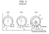
- the exterior surface 24 rotates hydro-dynamically on a hydraulic wedge of lubricant 40 in the seating surface 34 of the shoe 30, as shown in FIG. 3 .
- the wedge 40 lifts the roller 20 away from the shoe 30 so that during operation, there is negligible contact between the exterior surface 24 and the seating surface 34.
- an adequate length of roller is required.
- the exterior surface 24 of the roller 20 rotates in the seating surface 34 of the shoe 30 about an axis A1 in a direction indicated by the arrow J1, while the roller 20 translates in the shoe 30 in a direction indicated by the arrow K.
- the exterior surface 24 of the roller 20 rolls on the cam surface 22B as the cam 22 rotates around an axis A2 in the direction indicated by an arrow J2, which is opposite to the direction J1.
- edge portions 50A and 50B of the exterior surface 24, proximate the axial end 20X and 20Y, respectively are subject to high contact pressures and subsequent subsurface stresses in the material and tend to fail prematurely.
- a roller for a mechanical fuel pump assembly includes an elongate body extending from a first axial end to a second axial end of the elongate body over an overall length of the elongate body.
- the elongate body defines an effective length that is less than the overall length.
- the elongate body defines a uniform circular cross section over a second length of the elongate body. The second length is 75 to 90 percent of the effective length and the second length extends between a first plane and a second plane.
- a first area of reduced cross section extends axially outward from the first plane to a third plane located axially inward of the first axial end; and a second area of reduced cross section extends axially outward from the second plane to a fourth plane located axially inward of the second axial end.
- the first area of reduced cross section and/or the second area of reduced cross section has a profile having one or more radii of curvature.
- the radius of curvature is configured to relieve contact pressure proximate at least one of the first axial end and the second axial end.
- the invention also concerns a mechanical fuel pump assembly with a roller.
- a mechanical fuel pump 110 is similar to the mechanical fuel pump 10 of FIGS. 1A, 1B and 2 , thus similar elements are designated with similar element numbers preceded by the numeral 1.
- the mechanical fuel pump 110 includes a pump actuator 112 disposed in a housing 114.
- the fuel pump 110 includes a cam assembly 116 rotatably positioned in the housing 114 in proximity to the pump actuator 112.
- the cam assembly 116 includes a cam 122 mounted on a cam shaft 118.
- the cam 122 defines a cam surface 122B.
- the pump actuator 112 defines a substantially cylindrical body 112B having an interior surface 112C.
- a shoe 130 is pressed into in an interior defined by the interior surface 112C. The shoe 130 is pressed into the pump actuator body.
- the cam 122 has an axial width W2.
- the shoe 130 has an arcuate (e.g., circular contour) seating surface 134 extending diametrically across the shoe 130.
- the seating surface 134 is open a width W1 at the axial face 132.
- the arcuate seating surface 134 extends axially into the shoe 130 a depth D1 from the axial face 132 of the shoe 130.
- a roller 120 is rotatably disposed on the seating surface 134 so that a portion of the roller 120 extends outwardly from the axial face 132 of the shoe 130.
- the roller 120 has a diameter D2 (see FIG. 6A ) that is greater than the depth D1.
- the width W1 is about equal to or slightly greater than the diameter D2.
- a portion of the exterior surface of the roller 120 is an exterior cylindrical surface 124 as described herein.
- the exterior cylindrical surface 124 of the roller 120 is rotatable relative to the seating surface 134 of the shoe 130.
- the exterior cylindrical surface 124 rotates hydro-dynamically on a hydraulic wedge of lubricant 140 in the seating surface 134 of the shoe 130, as shown in FIG. 7 and similar to the wedge of lubricant 40 illustrated in FIG. 3 .
- the wedge 140 lifts the roller 120 away from the shoe 130 so that during operation, there is negligible contact between the exterior cylindrical surface 124 and the seating surface 134. To achieve adequate hydro-dynamic wedging and lift, an adequate length of roller is required.
- the exterior cylindrical surface 124 of the roller 120 rotates in the seating surface 134 of the shoe 130 about an axis A1 in a direction indicated by the arrow J1, while the roller 120 translates in the shoe 130 in a direction indicated by the arrow K.
- the exterior cylindrical surface 124 of the roller 120 rolls on the cam surface 122B as the cam 122 rotates around an axis A2 in the direction indicated by an arrow J2, which is opposite to the direction J1.
- the roller 120 for the mechanical fuel pump assembly 110 defines an elongate body 120 having an overall length L extending from a first axial end 126 to a second axial end 128 of the elongate body 120.
- the elongate body 120 defines an effective length L1 that extends from plane B to plane B'.
- the elongate body 120 defines a uniform circular cross section (i.e., cylindrical) over a second length L2 of the elongate body 120 that extends from plane A to plane A'.
- the second length L2 is 75 to 90 percent of the effective length L1 and the second length L2.
- the second length L2 is spaced apart from each of the plane B and plane B' by distance having a magnitude of about 5 percent to 12.5 percent of the effective length L1. In one embodiment, the second length L2 is 75 percent to 80 percent of the effective length L1. In one embodiment, the second length L2 is spaced apart from each of the plane B and plane B' by distance having a magnitude of about 10 percent to 12.5 percent of the effective length L1.
- the inventors have discovered that establishing the length L2 between 75 and 90 percent of the effective length L1 has unexpectedly yielded an optimization between hydro-dynamic wedging and lift, and a stress reduction proximate ends of the elongate body 120 (i.e., roller).
- the inventors have demonstrated unacceptable levels of stress proximate the ends 126 and 128 of the roller 120 when the second length L2 is greater than 90%, and demonstrated inadequate hydro-dynamic wedging and lift when the second length L2 is less than 75% of the first length L1.
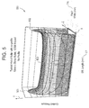
- the inventors conducted a contact pressure analysis of a roller with a constant cylindrical profile and plotted the results in a graph 500 as illustrated in FIG. 5 .
- the graph 500 shows contact pressure on a Y-axis, effective length L of the roller 20 on an X-axis and patch width PW on a Z-axis. As shown in FIG.
- the patch width PW is defined as the width of the contact area between the exterior cylindrical surface 124 or the profiled exterior surfaces 125 and 125' as shown in FIG. 6A and the cam surface 122B.
- the graph 500 of FIG. 5 indicates peak contact pressures at planes 501 and 502 of the roller 20, proximate the first axial end 20X to a second axial end 20Y of the roller 20.
- the peak contact pressures at planes 501 and 502 is about 140 percent of the contact pressure at an intermediate plane 503 of the roller 20.
- analysis of a roller having L2 at a magnitude of about 95% of the effective length L1 demonstrated contact pressures.
- the 10 is for a roller having a straight length L2 having a magnitude of 95% of the effective length L1.
- the graph 800 indicates contact pressures at planes 801 and 802 proximate the first axial end 20X to a second axial end 20Y of the roller 20 that lead to permanent deformation of the cam surface as well as to high subsurface stress in the cam material, and ultimately to spalling of the cam.
- the peak contact pressures at planes 801 and 802 is about 118 percent of the contact pressure at intermediate planes 803 of the roller.
- the elongate body 120 defines a first area of reduced cross section 160A extending axially outward from the plane A to the plane B; and a second area of reduced cross section 160B extending axially outward from the plane A' to the plane B'.
- the first area of reduced cross section 160A and/or the second area of reduced cross section 160B include a profile having one or more radii of curvature R.
- the radius of curvature R is configured to relieve contact stress proximate at least one of the first axial end 126 and the second axial end 128 and in particular on a surface 125 between the plane A and the plane B and on a surface 125' between the plane A' and the plane B'.
- one profile of the area of reduced cross section 160A is defined by a locust of points (DD n , RD n ), The distance DD n is defined axially inward from plane B in the direction of the arrow X'; and the drop RD n is defined radially inward from the exterior cylindrical surface 124 in the direction of the arrow AR.
- the uniform circular cross section over a second length L2 defines a exterior cylindrical surface 124 having surface finish and profile waviness heights of a magnitude less than that of a hydro-dynamic lubrication film 140 thickness T6 formed on the exterior cylindrical surface 124.
- the roller 120 is manufactured from a SAE 52100 steel.
- the roller 120 has a surface hardening (e.g., carbo-nitrided surface) of at least 65 Rockwell C scale.
- the surface hardening e.g., carbo-nitrided surface
- the surface hardening is about 0.5 mm deep.
- a graph 900 shows contact pressure on a Y-axis, effective length L of the roller 120 on an X-axis and patch width PW on a Z-axis, for one of the rollers 120 of the present invention as defined herein and as shown for example in FIG. 6A .
- the graph 900 illustrates that contact pressures at areas 601 and 602 proximate the first axial end 126 and the second axial end 128 of the roller 120 are less than contact pressures at intermediate points such as 603.
- the first axial end 126 and/or the second axial end 128 have a logarithmic profile.
- Drop is the radial roller drop on the axis R
- A is a constant based on the application and roller parameters
- Z is the total length of the profiled area of the roller along axis Z'
- Cyl_len is the cylindrical length of the roller
- x is the axial position along the roller from the center along the axis Z'.
Landscapes
- Engineering & Computer Science (AREA)
- General Engineering & Computer Science (AREA)
- Mechanical Engineering (AREA)
- Chemical & Material Sciences (AREA)
- Combustion & Propulsion (AREA)
- Fuel-Injection Apparatus (AREA)
Abstract
Description
- This invention relates to a roller for a fuel pump actuator and more particularly to a profile for a roller that optimizes hydrodynamic and rolling performance of the roller.
- Internal combustion engines use fuel pumps for delivery of fuel to combustion chambers of the engine. Fuel pumps include mechanical and electrical types. As shown in
FIG. 1A , amechanical fuel pump 10 includes apump actuator 12 disposed in ahousing 14. Thefuel pump 10 includes acam assembly 16 rotatably positioned in thehousing 14 in proximity to thepump actuator 12. Thecam assembly 16 includes acam 22 mounted on acam shaft 18. Thecam 22 defines acam surface 22B. - As shown in
FIG. 1B , thepump actuator 12 defines a substantiallycylindrical body 12B that has aninterior surface 12C. Ashoe 30 is press fit into theinterior surface 12C. Theactuator 12 slides (e.g., up and down or in and out) of abore 14B defined by thehousing 14. Thecam 22 has an axial width W2. Theshoe 30 has an arcuate (e.g., circular contour)seating surface 34 extending diametrically across theshoe 30. Theseating surface 34 is open a width W1 at anaxial face 32. Thearcuate seating surface 34 extends axially into the shoe 30 a depth D1, from theaxial face 32 of theshoe 30. Aroller 20 is rotatably disposed on theseating surface 34 so that a portion of theroller 20 extends outwardly from theaxial face 32 of theshoe 30. Theroller 20 has a diameter D2 that is greater than the depth D1. In one embodiment, the width W1 (in this particular case shown) is less than the roller diameter D1, such that theroller 20 has to be inserted axially and cannot fall out radially. This eases assembly/disassembly and avoids theroller 20 falling out should the roller leave the cam during operation. Theroller 20 defines a cylindricalexterior surface 24 that extends an overall length LX from a firstaxial end 20X to a secondaxial end 20Y of theroller 20. - The
exterior surface 24 of theroller 20 is rotatable relative to theseating surface 34 of theshoe 30. In particular, theexterior surface 24 rotates hydro-dynamically on a hydraulic wedge oflubricant 40 in theseating surface 34 of theshoe 30, as shown inFIG. 3 . Thewedge 40 lifts theroller 20 away from theshoe 30 so that during operation, there is negligible contact between theexterior surface 24 and theseating surface 34. However, to achieve adequate hydro-dynamic wedging and lift, an adequate length of roller is required. - As shown in
FIG. 4 , theexterior surface 24 of theroller 20 rotates in theseating surface 34 of theshoe 30 about an axis A1 in a direction indicated by the arrow J1, while theroller 20 translates in theshoe 30 in a direction indicated by the arrow K. Theexterior surface 24 of theroller 20 rolls on thecam surface 22B as thecam 22 rotates around an axis A2 in the direction indicated by an arrow J2, which is opposite to the direction J1. As a result of the rolling of theexterior surface 24 of theroller 20 on thecam surface 22B,edge portions exterior surface 24, proximate theaxial end graph 500 ofFIG. 5 indicates peak contact pressures atplanes roller 20, proximate the firstaxial end 20X to a secondaxial end 20Y of theroller 20. The peak contact pressures atplanes intermediate plane 503 of theroller 20. Attempts to reduce the high stress in theedge portions roller 20 to achieve adequate hydro-dynamic wedging and lift. In addition, efforts to maximize the length of theroller 20 to achieve adequate hydro-dynamic wedging and lift has worsened the stress in theend portions - Based on the foregoing, it is the general object of this invention to provide a roller and roller profile that optimize hydro-dynamic wedging and lift, and reduces stress on the
end portions - A roller for a mechanical fuel pump assembly includes an elongate body extending from a first axial end to a second axial end of the elongate body over an overall length of the elongate body. The elongate body defines an effective length that is less than the overall length. The elongate body defines a uniform circular cross section over a second length of the elongate body. The second length is 75 to 90 percent of the effective length and the second length extends between a first plane and a second plane. A first area of reduced cross section extends axially outward from the first plane to a third plane located axially inward of the first axial end; and a second area of reduced cross section extends axially outward from the second plane to a fourth plane located axially inward of the second axial end.
- In one embodiment, the first area of reduced cross section and/or the second area of reduced cross section has a profile having one or more radii of curvature. The radius of curvature is configured to relieve contact pressure proximate at least one of the first axial end and the second axial end. The invention also concerns a mechanical fuel pump assembly with a roller.
-
-
FIG. 1A is a cut away perspective view of a prior art mechanical fuel pump assembly; -
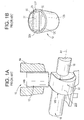
FIG. 1B is a bottom perspective view of the pump actuator of the fuel pump assembly ofFIG. 1A ; -
FIG. 2 is a perspective view of the roller and shoe portion of the pump actuator ofFIG. 1B ; -
FIG. 3 is a schematic view of hydro-dynamic wedging of the roller in the shoe ofFIGS. 1A, 1B and2 , showing static, start-up and running conditions; -
FIG. 4 is a cross sectional view of a portion of the fuel pump ofFIG. 1A ; -
FIG. 5 is a graph of contact pressure versus roller length and patch width of a standard roller with no profile; -
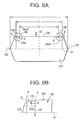
FIG. 6A is a cross sectional view of a roller of the present invention; -
FIG. 6B is an enlarged view ofdetail 6B ofFIG. 6A illustrating a roller profile; -
FIG. 7 is a cross sectional view of a fuel pump having the roller ofFIG. 5 disposed therein; -
FIG. 8 is a partial cross sectional view of a portion of the roller and cam ofFIG. 7 illustrating patch width; -
FIG. 9 is a graph of contact pressure versus roller length and patch width of the roller having the profile ofFIG. 6 ; -
FIG. 10 is a cross sectional view of another embodiment of the roller of the present invention illustrated with a 90 percent straight cylindrical section; and -
FIG. 11 is graph of a profile for a roller having a logarithmic profile on the ends thereof. - Referring to
FIG. 7 , amechanical fuel pump 110 is similar to themechanical fuel pump 10 ofFIGS. 1A, 1B and2 , thus similar elements are designated with similar element numbers preceded by the numeral 1. Themechanical fuel pump 110 includes apump actuator 112 disposed in ahousing 114. Thefuel pump 110 includes a cam assembly 116 rotatably positioned in thehousing 114 in proximity to thepump actuator 112. The cam assembly 116 includes acam 122 mounted on acam shaft 118. Thecam 122 defines acam surface 122B. Thepump actuator 112 defines a substantiallycylindrical body 112B having aninterior surface 112C. Ashoe 130 is pressed into in an interior defined by theinterior surface 112C. Theshoe 130 is pressed into the pump actuator body. Thecam 122 has an axial width W2. Theshoe 130 has an arcuate (e.g., circular contour)seating surface 134 extending diametrically across theshoe 130. Theseating surface 134 is open a width W1 at theaxial face 132. Thearcuate seating surface 134 extends axially into the shoe 130 a depth D1 from theaxial face 132 of theshoe 130. Aroller 120 is rotatably disposed on theseating surface 134 so that a portion of theroller 120 extends outwardly from theaxial face 132 of theshoe 130. Theroller 120 has a diameter D2 (seeFIG. 6A ) that is greater than the depth D1. The width W1 is about equal to or slightly greater than the diameter D2. A portion of the exterior surface of theroller 120 is an exteriorcylindrical surface 124 as described herein. - The exterior
cylindrical surface 124 of theroller 120 is rotatable relative to theseating surface 134 of theshoe 130. In particular, the exteriorcylindrical surface 124 rotates hydro-dynamically on a hydraulic wedge oflubricant 140 in theseating surface 134 of theshoe 130, as shown inFIG. 7 and similar to the wedge oflubricant 40 illustrated inFIG. 3 . Thewedge 140 lifts theroller 120 away from theshoe 130 so that during operation, there is negligible contact between the exteriorcylindrical surface 124 and theseating surface 134. To achieve adequate hydro-dynamic wedging and lift, an adequate length of roller is required. - As shown in
FIG. 7 , the exteriorcylindrical surface 124 of theroller 120 rotates in theseating surface 134 of theshoe 130 about an axis A1 in a direction indicated by the arrow J1, while theroller 120 translates in theshoe 130 in a direction indicated by the arrow K. The exteriorcylindrical surface 124 of theroller 120 rolls on thecam surface 122B as thecam 122 rotates around an axis A2 in the direction indicated by an arrow J2, which is opposite to the direction J1. - As shown in
FIGS. 6A and7 , theroller 120 for the mechanicalfuel pump assembly 110, defines anelongate body 120 having an overall length L extending from a firstaxial end 126 to a secondaxial end 128 of theelongate body 120. Theelongate body 120 defines an effective length L1 that extends from plane B to plane B'. Theelongate body 120 defines a uniform circular cross section (i.e., cylindrical) over a second length L2 of theelongate body 120 that extends from plane A to plane A'. The second length L2 is 75 to 90 percent of the effective length L1 and the second length L2. The second length L2 is spaced apart from each of the plane B and plane B' by distance having a magnitude of about 5 percent to 12.5 percent of the effective length L1. In one embodiment, the second length L2 is 75 percent to 80 percent of the effective length L1. In one embodiment, the second length L2 is spaced apart from each of the plane B and plane B' by distance having a magnitude of about 10 percent to 12.5 percent of the effective length L1. The inventors have discovered that establishing the length L2 between 75 and 90 percent of the effective length L1 has unexpectedly yielded an optimization between hydro-dynamic wedging and lift, and a stress reduction proximate ends of the elongate body 120 (i.e., roller). - Via analysis and testing the inventors have demonstrated unacceptable levels of stress proximate the
ends roller 120 when the second length L2 is greater than 90%, and demonstrated inadequate hydro-dynamic wedging and lift when the second length L2 is less than 75% of the first length L1. For example, the inventors conducted a contact pressure analysis of a roller with a constant cylindrical profile and plotted the results in agraph 500 as illustrated inFIG. 5 . Thegraph 500 shows contact pressure on a Y-axis, effective length L of theroller 20 on an X-axis and patch width PW on a Z-axis. As shown inFIG. 8 , the patch width PW is defined as the width of the contact area between the exteriorcylindrical surface 124 or the profiledexterior surfaces 125 and 125' as shown inFIG. 6A and thecam surface 122B. Thegraph 500 ofFIG. 5 indicates peak contact pressures atplanes roller 20, proximate the firstaxial end 20X to a secondaxial end 20Y of theroller 20. The peak contact pressures atplanes intermediate plane 503 of theroller 20. In addition, analysis of a roller having L2 at a magnitude of about 95% of the effective length L1 demonstrated contact pressures. For example, thegraph 800 ofFIG. 10 is for a roller having a straight length L2 having a magnitude of 95% of the effective length L1. Thegraph 800 indicates contact pressures atplanes axial end 20X to a secondaxial end 20Y of theroller 20 that lead to permanent deformation of the cam surface as well as to high subsurface stress in the cam material, and ultimately to spalling of the cam. The peak contact pressures atplanes intermediate planes 803 of the roller. - Still referring to
FIGS. 6a and7 , theelongate body 120 defines a first area of reducedcross section 160A extending axially outward from the plane A to the plane B; and a second area of reducedcross section 160B extending axially outward from the plane A' to the plane B'. As best shown inFIG. 6B , the first area of reducedcross section 160A and/or the second area of reducedcross section 160B include a profile having one or more radii of curvature R. In one embodiment, the radius of curvature R is configured to relieve contact stress proximate at least one of the firstaxial end 126 and the secondaxial end 128 and in particular on asurface 125 between the plane A and the plane B and on a surface 125' between the plane A' and the plane B'. A shown inFIG. 6B , one profile of the area of reducedcross section 160A is defined by a locust of points (DDn, RDn), The distance DDn is defined axially inward from plane B in the direction of the arrow X'; and the drop RDn is defined radially inward from the exteriorcylindrical surface 124 in the direction of the arrow AR. - The uniform circular cross section over a second length L2 defines a exterior
cylindrical surface 124 having surface finish and profile waviness heights of a magnitude less than that of a hydro-dynamic lubrication film 140 thickness T6 formed on the exteriorcylindrical surface 124. In one embodiment, theroller 120 is manufactured from a SAE 52100 steel. Theroller 120 has a surface hardening (e.g., carbo-nitrided surface) of at least 65 Rockwell C scale. The surface hardening (e.g., carbo-nitrided surface) is about 0.5 mm deep. - As shown in
FIG, 9 , agraph 900 shows contact pressure on a Y-axis, effective length L of theroller 120 on an X-axis and patch width PW on a Z-axis, for one of therollers 120 of the present invention as defined herein and as shown for example inFIG. 6A . Thegraph 900 illustrates that contact pressures atareas axial end 126 and the secondaxial end 128 of theroller 120 are less than contact pressures at intermediate points such as 603. - As shown in
FIG. 11 , in one embodiment, the firstaxial end 126 and/or the secondaxial end 128 have a logarithmic profile. As shown ingraph 900 ofFIG. 11 and Table 2 below, the logarithmic profile is defined by the formula:
- Drop is the radial roller drop on the axis R, A is a constant based on the application and roller parameters, Z is the total length of the profiled area of the roller along axis Z', Cyl_len is the cylindrical length of the roller and x is the axial position along the roller from the center along the axis Z'.
- Although the invention has been described with reference to particular embodiments thereof, it will be understood by one of ordinary skill in the art, upon a reading and understanding of the foregoing disclosure that numerous variations and alterations to the disclosed embodiments will fall within the spirit and scope of this invention and of the appended claims.
Claims (13)
- A roller (120) for a mechanical fuel pump assembly (110), the roller (120) comprising:an elongate body (120) extending from a first axial end (126) to a second axial end (128) of the elongate body (120) over an overall length (L) of the elongate body (120), the elongate body (120) defining an effective length (L1) that is less than the overall length (L);the elongate body (120) defining a uniform circular cross section over a second length (L2) of the elongate body (120), the second length (L2) being 75 to 90 percent of the effective length (L1) and the second length (L2) extending between a first plane (A) and a second plane (A');a first area of reduced cross section (160A) extending axially outward from the first plane (A) to a third plane (B) located axially inward of the first axial end; anda second area of reduced cross section (160B) extending axially outward from the second plane (A') to a fourth plane (B') located axially inward of the second axial end (128).
- The roller (120) of claim 1, wherein at least one of the first area of reduced cross section (160A) and the second area of reduced cross section (160B) comprises a profile having at least one radius of curvature (R).
- The roller (120) of claim 2, wherein the at least one radius of curvature (R) is configured to relieve contact stress proximate at least one of the first axial end (126) and the second axial end (128).
- The roller (120) of claim 1, wherein the second length (L2) is spaced apart from each of the first end (126) and the second end (128) by distance having a magnitude of about 5 percent to 12.5 percent of the first length (L1).
- The roller (120) of claim 1, wherein the second length (L2) is 75 percent to 80 percent of the first length (L1).
- The roller (120) of claim 5, wherein the second length (L2) is spaced apart from each of the first end (126) and the second end (128) by distance having a magnitude of about 10 percent to 12.5 percent of the first length (L1).
- The roller (120) of claim 1, wherein the uniform circular cross section over a second length (L2) defines a exterior cylindrical surface (124) having surface finish and profile waviness heights is a magnitude less than that of a hydro-dynamic lubrication film (140) thickness (T6) formed on the cylindrical surface.
- The roller (120) of claim 1, wherein the roller (120) comprises SAE 52100 steel.
- The roller (120) of claim 8, wherein the roller (120) has a surface hardening of at least 65 Rockwell C scale.
- The roller (120) of claim 6, wherein the carbo-nitride surface hardening is about 0.5 mm deep.
- The roller (120) of claim 9, wherein the surface hardening is carbo-nitriding.
- The roller (120) of claim 1, further comprising a logarithmic profile proximate at least one of the first axial end (126) and the second axial end (128).
- A mechanical fuel pump assembly (110) comprising:a housing (114),a fuel pump actuator (112) disposed in the housing (114), the fuel pump actuator (112) having an interior surface (112C),a shoe (130) pressed into the interior surface (112C), the shoe (130) having an arcuate seating surface (134) extending diametrically across the shoe (130),a roller (120) according to any one of the preceding claims rotatably deposed on the seating surface (134),a cam (122), defining a cam surface (122B), wherein the roller (120) has an exterior cylindrical surface (124) arranged to roll on the cam surface (122B) as the cam (122) rotates around an axis (A2).
Applications Claiming Priority (1)
| Application Number | Priority Date | Filing Date | Title |
|---|---|---|---|
| US201562102832P | 2015-01-13 | 2015-01-13 |
Publications (2)
| Publication Number | Publication Date |
|---|---|
| EP3048293A1 true EP3048293A1 (en) | 2016-07-27 |
| EP3048293B1 EP3048293B1 (en) | 2019-09-18 |
Family
ID=55168150
Family Applications (1)
| Application Number | Title | Priority Date | Filing Date |
|---|---|---|---|
| EP16151075.5A Active EP3048293B1 (en) | 2015-01-13 | 2016-01-13 | Roller for fuel pump actuator |
Country Status (2)
| Country | Link |
|---|---|
| US (1) | US9835123B2 (en) |
| EP (1) | EP3048293B1 (en) |
Families Citing this family (3)
| Publication number | Priority date | Publication date | Assignee | Title |
|---|---|---|---|---|
| JP2021032100A (en) * | 2019-08-21 | 2021-03-01 | 株式会社デンソー | Fuel injection pump |
| WO2022036230A1 (en) * | 2020-08-14 | 2022-02-17 | Cummins Inc. | Sliding cam follower |
| CN213807956U (en) * | 2020-09-02 | 2021-07-27 | 罗伯特·博世有限公司 | Plunger pump tappet assembly and its roller |
Citations (4)
| Publication number | Priority date | Publication date | Assignee | Title |
|---|---|---|---|---|
| DE102009002520A1 (en) * | 2009-04-21 | 2010-10-28 | Robert Bosch Gmbh | High-pressure pump, particularly radial piston pump or in-line piston pump for fuel injection systems of air-compressing, self-ignited internal combustion engines, has pump assembly and drive shaft |
| DE102009028373A1 (en) * | 2009-08-10 | 2011-02-17 | Robert Bosch Gmbh | high pressure pump |
| DE102010027792A1 (en) * | 2010-04-15 | 2011-10-20 | Robert Bosch Gmbh | high pressure pump |
| DE102010041178A1 (en) * | 2010-09-22 | 2012-03-22 | Robert Bosch Gmbh | Pump i.e. high-pressure fuel pump, for fuel injector of internal combustion engine, has roller comprising central portion and edge areas in direction of axis of shaft, where portion and areas are longitudinally formed away from track |
Family Cites Families (33)
| Publication number | Priority date | Publication date | Assignee | Title |
|---|---|---|---|---|
| US3620585A (en) * | 1970-01-16 | 1971-11-16 | Nasa | High-speed rolling element bearing |
| US3667822A (en) * | 1971-03-01 | 1972-06-06 | Lipe Rollway Corp | Coned end roller bearing |
| NL8601464A (en) | 1986-06-06 | 1988-01-04 | Philips Nv | AXIAL BEARING WITH A RESERVOIR WITH A PATTERN OF TRANSPORT GROOVES. |
| JP2551090B2 (en) * | 1988-03-04 | 1996-11-06 | 日本精工株式会社 | Spherical roller bearing |
| SE511031C2 (en) * | 1997-04-24 | 1999-07-26 | Skf Ab | Roll bearing with symmetrically thin shaped rollers |
| US6210503B1 (en) | 1997-11-13 | 2001-04-03 | Cummins Engine Company, Inc. | Roller pin materials for enhanced cam durability |
| JP3731401B2 (en) * | 1999-08-31 | 2006-01-05 | 日本精工株式会社 | Roller bearing |
| US6354745B1 (en) * | 1999-09-16 | 2002-03-12 | The Timken Company | Fully self-aligning roller bearing |
| EP1298334A3 (en) * | 2001-09-26 | 2005-11-16 | Ntn Corporation | Roller thrust bearing |
| US7114854B2 (en) * | 2002-11-07 | 2006-10-03 | Ntn Corporation | Thrust roller bearing and cage |
| US7311087B2 (en) | 2004-11-23 | 2007-12-25 | Cummins Inc. | Fuel pump with a guided tappet assembly and methods for guiding and assembly |
| DE102005019984A1 (en) | 2005-04-27 | 2006-11-09 | A. Friedr. Flender Ag | plain bearing |
| GB0519680D0 (en) | 2005-09-27 | 2005-11-02 | Delphi Tech Inc | Fuel pump assembly |
| DE102006012458A1 (en) | 2006-03-17 | 2007-09-20 | Robert Bosch Gmbh | Roller tappet for a pump element of a high-pressure fuel pump |
| DE102006045933A1 (en) * | 2006-09-28 | 2008-04-03 | Robert Bosch Gmbh | Plunger assembly for a high pressure pump and high pressure pump with at least one plunger assembly |
| DE102007012704A1 (en) * | 2007-03-16 | 2008-09-18 | Robert Bosch Gmbh | High pressure pump for delivering fuel with an improved design of the bearing assembly for supporting the camshaft |
| JP2010001828A (en) | 2008-06-20 | 2010-01-07 | Toyota Motor Corp | High pressure fuel pump |
| US7568461B1 (en) | 2008-06-20 | 2009-08-04 | Gm Global Technology Operations, Inc. | Tappet roller end shape for improved lubrication and combination with fuel pump and engine |
| DE102008042378A1 (en) | 2008-09-26 | 2010-04-01 | Robert Bosch Gmbh | Eccentric cam engine, particularly for high-pressure fuel pump, has rotatably mounted eccentric cam, where piston interacts with eccentric cam, and multiple roller elements are provided in roller bearing |
| DE102008043847A1 (en) | 2008-11-19 | 2010-05-20 | Robert Bosch Gmbh | High-pressure pump e.g. radial piston pump, for fuel injection system of e.g. self-igniting internal-combustion engine, has pump assembly, and drive shaft with cam, where angles to axis of pump assembly are preset for respective gap areas |
| DE202008016385U1 (en) | 2008-12-11 | 2010-04-22 | Ab Skf | The torque transfer device |
| DE102009003054A1 (en) | 2009-05-13 | 2010-11-18 | Robert Bosch Gmbh | high pressure pump |
| DE102011002701A1 (en) | 2011-01-14 | 2012-07-19 | Robert Bosch Gmbh | high pressure pump |
| DE102011002745A1 (en) | 2011-01-17 | 2012-07-19 | Robert Bosch Gmbh | Hydrodynamic plain bearing for high-pressure fuel pump for fuel injection system of internal combustion engine, has bearing main portion with large wrap angle between force application point and cross-section of fluid exit gap |
| DE102011003245A1 (en) | 2011-01-27 | 2012-08-02 | Schaeffler Technologies Gmbh & Co. Kg | Cup tappet for acting on a pump piston of a high-pressure fuel pump |
| KR20140019539A (en) * | 2012-08-06 | 2014-02-17 | 현대자동차주식회사 | Roller structure of high pressure pump |
| KR101371897B1 (en) * | 2012-09-05 | 2014-03-07 | 현대자동차주식회사 | High pressure fuel pump improving lubrication |
| DE102012221765A1 (en) | 2012-11-28 | 2014-05-28 | Robert Bosch Gmbh | Pump, particularly high-pressure fuel pump for fuel injection system, has support element with opening between recess and side on which pump piston is supported, where opening extends approximately along recess |
| US9777767B2 (en) * | 2013-07-19 | 2017-10-03 | The Timken Company | Relief contour for a roller bearing |
| DE102013221196A1 (en) | 2013-10-18 | 2015-04-23 | Robert Bosch Gmbh | high pressure pump |
| DE102013224797A1 (en) | 2013-12-04 | 2015-06-11 | Robert Bosch Gmbh | Fuel pump with a piston, at its end facing a drive end a spring divider is arranged |
| US9546724B2 (en) | 2014-01-13 | 2017-01-17 | Caterpillar Inc. | Roller pin for cam actuated roller assembly |
| US9567960B2 (en) | 2014-03-25 | 2017-02-14 | Cummins Inc. | Fuel pump tappet assembly |
-
2016
- 2016-01-12 US US14/993,620 patent/US9835123B2/en not_active Expired - Fee Related
- 2016-01-13 EP EP16151075.5A patent/EP3048293B1/en active Active
Patent Citations (4)
| Publication number | Priority date | Publication date | Assignee | Title |
|---|---|---|---|---|
| DE102009002520A1 (en) * | 2009-04-21 | 2010-10-28 | Robert Bosch Gmbh | High-pressure pump, particularly radial piston pump or in-line piston pump for fuel injection systems of air-compressing, self-ignited internal combustion engines, has pump assembly and drive shaft |
| DE102009028373A1 (en) * | 2009-08-10 | 2011-02-17 | Robert Bosch Gmbh | high pressure pump |
| DE102010027792A1 (en) * | 2010-04-15 | 2011-10-20 | Robert Bosch Gmbh | high pressure pump |
| DE102010041178A1 (en) * | 2010-09-22 | 2012-03-22 | Robert Bosch Gmbh | Pump i.e. high-pressure fuel pump, for fuel injector of internal combustion engine, has roller comprising central portion and edge areas in direction of axis of shaft, where portion and areas are longitudinally formed away from track |
Also Published As
| Publication number | Publication date |
|---|---|
| US9835123B2 (en) | 2017-12-05 |
| EP3048293B1 (en) | 2019-09-18 |
| US20160201630A1 (en) | 2016-07-14 |
Similar Documents
| Publication | Publication Date | Title |
|---|---|---|
| EP1886033B1 (en) | Thrust bearing | |
| KR101200313B1 (en) | Thrust bearing assembly | |
| US8147144B2 (en) | Connecting rod bearing for internal combustion engines | |
| US8905639B2 (en) | Main bearing for crankshaft of internal combustion engine | |
| EP2562448A1 (en) | Oil ring for internal combustion engine | |
| EP2631500B1 (en) | Bearing apparatus for crankshaft of internal combustion engine | |
| EP2578908A1 (en) | Oil ring for internal combustion engine | |
| EP3048293B1 (en) | Roller for fuel pump actuator | |
| US10145409B2 (en) | Bearing apparatus of crankshaft for internal combustion engine | |
| EP2924292B1 (en) | Rotary compressor | |
| EP2423524A1 (en) | Thrust roller bearing and method of manufacturing thrust race thereof | |
| US20050213859A1 (en) | Sliding bearing | |
| EP2253859A1 (en) | Slide bearing | |
| CN102099591A (en) | Pressed cage, self-aligning roller bearing, and method of manufacturing pressed cage | |
| US9194427B2 (en) | Bearing device | |
| JP6130862B2 (en) | Method and tool for increasing the strength of a shaft, in particular a crankshaft | |
| KR20040088068A (en) | Pulley bearing for engine auxiliaries | |
| US20130016934A1 (en) | Sliding bearing shell | |
| US7252436B2 (en) | Roller bearing cage and method of producing the same | |
| US6460498B2 (en) | Rocker arm | |
| EP3693626B1 (en) | Retainer for rolling bearing | |
| EP3267055A1 (en) | Bearing device for crankshaft of internal combustion engine | |
| WO2014032687A1 (en) | Crankshaft assembly | |
| EP2587058B1 (en) | Bent axis type hydraulic rotating machine | |
| US20070065061A1 (en) | Crankshaft supporting structure |
Legal Events
| Date | Code | Title | Description |
|---|---|---|---|
| PUAI | Public reference made under article 153(3) epc to a published international application that has entered the european phase |
Free format text: ORIGINAL CODE: 0009012 |
|
| AK | Designated contracting states |
Kind code of ref document: A1 Designated state(s): AL AT BE BG CH CY CZ DE DK EE ES FI FR GB GR HR HU IE IS IT LI LT LU LV MC MK MT NL NO PL PT RO RS SE SI SK SM TR |
|
| AX | Request for extension of the european patent |
Extension state: BA ME |
|
| STAA | Information on the status of an ep patent application or granted ep patent |
Free format text: STATUS: REQUEST FOR EXAMINATION WAS MADE |
|
| 17P | Request for examination filed |
Effective date: 20170127 |
|
| RBV | Designated contracting states (corrected) |
Designated state(s): AL AT BE BG CH CY CZ DE DK EE ES FI FR GB GR HR HU IE IS IT LI LT LU LV MC MK MT NL NO PL PT RO RS SE SI SK SM TR |
|
| STAA | Information on the status of an ep patent application or granted ep patent |
Free format text: STATUS: EXAMINATION IS IN PROGRESS |
|
| 17Q | First examination report despatched |
Effective date: 20180612 |
|
| GRAP | Despatch of communication of intention to grant a patent |
Free format text: ORIGINAL CODE: EPIDOSNIGR1 |
|
| STAA | Information on the status of an ep patent application or granted ep patent |
Free format text: STATUS: GRANT OF PATENT IS INTENDED |
|
| INTG | Intention to grant announced |
Effective date: 20190509 |
|
| GRAS | Grant fee paid |
Free format text: ORIGINAL CODE: EPIDOSNIGR3 |
|
| GRAA | (expected) grant |
Free format text: ORIGINAL CODE: 0009210 |
|
| STAA | Information on the status of an ep patent application or granted ep patent |
Free format text: STATUS: THE PATENT HAS BEEN GRANTED |
|
| AK | Designated contracting states |
Kind code of ref document: B1 Designated state(s): AL AT BE BG CH CY CZ DE DK EE ES FI FR GB GR HR HU IE IS IT LI LT LU LV MC MK MT NL NO PL PT RO RS SE SI SK SM TR |
|
| REG | Reference to a national code |
Ref country code: GB Ref legal event code: FG4D |
|
| REG | Reference to a national code |
Ref country code: CH Ref legal event code: EP |
|
| REG | Reference to a national code |
Ref country code: DE Ref legal event code: R096 Ref document number: 602016020661 Country of ref document: DE |
|
| REG | Reference to a national code |
Ref country code: AT Ref legal event code: REF Ref document number: 1181597 Country of ref document: AT Kind code of ref document: T Effective date: 20191015 |
|
| REG | Reference to a national code |
Ref country code: IE Ref legal event code: FG4D |
|
| REG | Reference to a national code |
Ref country code: NL Ref legal event code: MP Effective date: 20190918 |
|
| PG25 | Lapsed in a contracting state [announced via postgrant information from national office to epo] |
Ref country code: NO Free format text: LAPSE BECAUSE OF FAILURE TO SUBMIT A TRANSLATION OF THE DESCRIPTION OR TO PAY THE FEE WITHIN THE PRESCRIBED TIME-LIMIT Effective date: 20191218 Ref country code: FI Free format text: LAPSE BECAUSE OF FAILURE TO SUBMIT A TRANSLATION OF THE DESCRIPTION OR TO PAY THE FEE WITHIN THE PRESCRIBED TIME-LIMIT Effective date: 20190918 Ref country code: LT Free format text: LAPSE BECAUSE OF FAILURE TO SUBMIT A TRANSLATION OF THE DESCRIPTION OR TO PAY THE FEE WITHIN THE PRESCRIBED TIME-LIMIT Effective date: 20190918 Ref country code: HR Free format text: LAPSE BECAUSE OF FAILURE TO SUBMIT A TRANSLATION OF THE DESCRIPTION OR TO PAY THE FEE WITHIN THE PRESCRIBED TIME-LIMIT Effective date: 20190918 Ref country code: BG Free format text: LAPSE BECAUSE OF FAILURE TO SUBMIT A TRANSLATION OF THE DESCRIPTION OR TO PAY THE FEE WITHIN THE PRESCRIBED TIME-LIMIT Effective date: 20191218 Ref country code: SE Free format text: LAPSE BECAUSE OF FAILURE TO SUBMIT A TRANSLATION OF THE DESCRIPTION OR TO PAY THE FEE WITHIN THE PRESCRIBED TIME-LIMIT Effective date: 20190918 |
|
| REG | Reference to a national code |
Ref country code: LT Ref legal event code: MG4D |
|
| PG25 | Lapsed in a contracting state [announced via postgrant information from national office to epo] |
Ref country code: GR Free format text: LAPSE BECAUSE OF FAILURE TO SUBMIT A TRANSLATION OF THE DESCRIPTION OR TO PAY THE FEE WITHIN THE PRESCRIBED TIME-LIMIT Effective date: 20191219 Ref country code: LV Free format text: LAPSE BECAUSE OF FAILURE TO SUBMIT A TRANSLATION OF THE DESCRIPTION OR TO PAY THE FEE WITHIN THE PRESCRIBED TIME-LIMIT Effective date: 20190918 Ref country code: AL Free format text: LAPSE BECAUSE OF FAILURE TO SUBMIT A TRANSLATION OF THE DESCRIPTION OR TO PAY THE FEE WITHIN THE PRESCRIBED TIME-LIMIT Effective date: 20190918 Ref country code: RS Free format text: LAPSE BECAUSE OF FAILURE TO SUBMIT A TRANSLATION OF THE DESCRIPTION OR TO PAY THE FEE WITHIN THE PRESCRIBED TIME-LIMIT Effective date: 20190918 |
|
| REG | Reference to a national code |
Ref country code: AT Ref legal event code: MK05 Ref document number: 1181597 Country of ref document: AT Kind code of ref document: T Effective date: 20190918 |
|
| PG25 | Lapsed in a contracting state [announced via postgrant information from national office to epo] |
Ref country code: RO Free format text: LAPSE BECAUSE OF FAILURE TO SUBMIT A TRANSLATION OF THE DESCRIPTION OR TO PAY THE FEE WITHIN THE PRESCRIBED TIME-LIMIT Effective date: 20190918 Ref country code: IT Free format text: LAPSE BECAUSE OF FAILURE TO SUBMIT A TRANSLATION OF THE DESCRIPTION OR TO PAY THE FEE WITHIN THE PRESCRIBED TIME-LIMIT Effective date: 20190918 Ref country code: PL Free format text: LAPSE BECAUSE OF FAILURE TO SUBMIT A TRANSLATION OF THE DESCRIPTION OR TO PAY THE FEE WITHIN THE PRESCRIBED TIME-LIMIT Effective date: 20190918 Ref country code: AT Free format text: LAPSE BECAUSE OF FAILURE TO SUBMIT A TRANSLATION OF THE DESCRIPTION OR TO PAY THE FEE WITHIN THE PRESCRIBED TIME-LIMIT Effective date: 20190918 Ref country code: NL Free format text: LAPSE BECAUSE OF FAILURE TO SUBMIT A TRANSLATION OF THE DESCRIPTION OR TO PAY THE FEE WITHIN THE PRESCRIBED TIME-LIMIT Effective date: 20190918 Ref country code: ES Free format text: LAPSE BECAUSE OF FAILURE TO SUBMIT A TRANSLATION OF THE DESCRIPTION OR TO PAY THE FEE WITHIN THE PRESCRIBED TIME-LIMIT Effective date: 20190918 Ref country code: PT Free format text: LAPSE BECAUSE OF FAILURE TO SUBMIT A TRANSLATION OF THE DESCRIPTION OR TO PAY THE FEE WITHIN THE PRESCRIBED TIME-LIMIT Effective date: 20200120 Ref country code: EE Free format text: LAPSE BECAUSE OF FAILURE TO SUBMIT A TRANSLATION OF THE DESCRIPTION OR TO PAY THE FEE WITHIN THE PRESCRIBED TIME-LIMIT Effective date: 20190918 |
|
| PG25 | Lapsed in a contracting state [announced via postgrant information from national office to epo] |
Ref country code: CZ Free format text: LAPSE BECAUSE OF FAILURE TO SUBMIT A TRANSLATION OF THE DESCRIPTION OR TO PAY THE FEE WITHIN THE PRESCRIBED TIME-LIMIT Effective date: 20190918 Ref country code: SM Free format text: LAPSE BECAUSE OF FAILURE TO SUBMIT A TRANSLATION OF THE DESCRIPTION OR TO PAY THE FEE WITHIN THE PRESCRIBED TIME-LIMIT Effective date: 20190918 Ref country code: SK Free format text: LAPSE BECAUSE OF FAILURE TO SUBMIT A TRANSLATION OF THE DESCRIPTION OR TO PAY THE FEE WITHIN THE PRESCRIBED TIME-LIMIT Effective date: 20190918 Ref country code: IS Free format text: LAPSE BECAUSE OF FAILURE TO SUBMIT A TRANSLATION OF THE DESCRIPTION OR TO PAY THE FEE WITHIN THE PRESCRIBED TIME-LIMIT Effective date: 20200224 |
|
| REG | Reference to a national code |
Ref country code: DE Ref legal event code: R097 Ref document number: 602016020661 Country of ref document: DE |
|
| PLBE | No opposition filed within time limit |
Free format text: ORIGINAL CODE: 0009261 |
|
| STAA | Information on the status of an ep patent application or granted ep patent |
Free format text: STATUS: NO OPPOSITION FILED WITHIN TIME LIMIT |
|
| PG2D | Information on lapse in contracting state deleted |
Ref country code: IS |
|
| PG25 | Lapsed in a contracting state [announced via postgrant information from national office to epo] |
Ref country code: DK Free format text: LAPSE BECAUSE OF FAILURE TO SUBMIT A TRANSLATION OF THE DESCRIPTION OR TO PAY THE FEE WITHIN THE PRESCRIBED TIME-LIMIT Effective date: 20190918 Ref country code: IS Free format text: LAPSE BECAUSE OF FAILURE TO SUBMIT A TRANSLATION OF THE DESCRIPTION OR TO PAY THE FEE WITHIN THE PRESCRIBED TIME-LIMIT Effective date: 20200119 |
|
| 26N | No opposition filed |
Effective date: 20200619 |
|
| PG25 | Lapsed in a contracting state [announced via postgrant information from national office to epo] |
Ref country code: MC Free format text: LAPSE BECAUSE OF FAILURE TO SUBMIT A TRANSLATION OF THE DESCRIPTION OR TO PAY THE FEE WITHIN THE PRESCRIBED TIME-LIMIT Effective date: 20190918 Ref country code: SI Free format text: LAPSE BECAUSE OF FAILURE TO SUBMIT A TRANSLATION OF THE DESCRIPTION OR TO PAY THE FEE WITHIN THE PRESCRIBED TIME-LIMIT Effective date: 20190918 |
|
| REG | Reference to a national code |
Ref country code: CH Ref legal event code: PL |
|
| GBPC | Gb: european patent ceased through non-payment of renewal fee |
Effective date: 20200113 |
|
| REG | Reference to a national code |
Ref country code: BE Ref legal event code: MM Effective date: 20200131 |
|
| PG25 | Lapsed in a contracting state [announced via postgrant information from national office to epo] |
Ref country code: FR Free format text: LAPSE BECAUSE OF NON-PAYMENT OF DUE FEES Effective date: 20200131 Ref country code: GB Free format text: LAPSE BECAUSE OF NON-PAYMENT OF DUE FEES Effective date: 20200113 Ref country code: LU Free format text: LAPSE BECAUSE OF NON-PAYMENT OF DUE FEES Effective date: 20200113 |
|
| PG25 | Lapsed in a contracting state [announced via postgrant information from national office to epo] |
Ref country code: LI Free format text: LAPSE BECAUSE OF NON-PAYMENT OF DUE FEES Effective date: 20200131 Ref country code: BE Free format text: LAPSE BECAUSE OF NON-PAYMENT OF DUE FEES Effective date: 20200131 Ref country code: CH Free format text: LAPSE BECAUSE OF NON-PAYMENT OF DUE FEES Effective date: 20200131 |
|
| PG25 | Lapsed in a contracting state [announced via postgrant information from national office to epo] |
Ref country code: IE Free format text: LAPSE BECAUSE OF NON-PAYMENT OF DUE FEES Effective date: 20200113 |
|
| PG25 | Lapsed in a contracting state [announced via postgrant information from national office to epo] |
Ref country code: TR Free format text: LAPSE BECAUSE OF FAILURE TO SUBMIT A TRANSLATION OF THE DESCRIPTION OR TO PAY THE FEE WITHIN THE PRESCRIBED TIME-LIMIT Effective date: 20190918 Ref country code: MT Free format text: LAPSE BECAUSE OF FAILURE TO SUBMIT A TRANSLATION OF THE DESCRIPTION OR TO PAY THE FEE WITHIN THE PRESCRIBED TIME-LIMIT Effective date: 20190918 Ref country code: CY Free format text: LAPSE BECAUSE OF FAILURE TO SUBMIT A TRANSLATION OF THE DESCRIPTION OR TO PAY THE FEE WITHIN THE PRESCRIBED TIME-LIMIT Effective date: 20190918 |
|
| PG25 | Lapsed in a contracting state [announced via postgrant information from national office to epo] |
Ref country code: MK Free format text: LAPSE BECAUSE OF FAILURE TO SUBMIT A TRANSLATION OF THE DESCRIPTION OR TO PAY THE FEE WITHIN THE PRESCRIBED TIME-LIMIT Effective date: 20190918 |
|
| PGFP | Annual fee paid to national office [announced via postgrant information from national office to epo] |
Ref country code: DE Payment date: 20230123 Year of fee payment: 8 |
|
| REG | Reference to a national code |
Ref country code: DE Ref legal event code: R119 Ref document number: 602016020661 Country of ref document: DE |
|
| PG25 | Lapsed in a contracting state [announced via postgrant information from national office to epo] |
Ref country code: DE Free format text: LAPSE BECAUSE OF NON-PAYMENT OF DUE FEES Effective date: 20240801 |
|
| PG25 | Lapsed in a contracting state [announced via postgrant information from national office to epo] |
Ref country code: DE Free format text: LAPSE BECAUSE OF NON-PAYMENT OF DUE FEES Effective date: 20240801 |