EP3048256A1 - Rotor comprising a turbine blade with a locking device - Google Patents
Rotor comprising a turbine blade with a locking device Download PDFInfo
- Publication number
- EP3048256A1 EP3048256A1 EP15151806.5A EP15151806A EP3048256A1 EP 3048256 A1 EP3048256 A1 EP 3048256A1 EP 15151806 A EP15151806 A EP 15151806A EP 3048256 A1 EP3048256 A1 EP 3048256A1
- Authority
- EP
- European Patent Office
- Prior art keywords
- rotor
- recess
- turbine blade
- holding piece
- blade root
- Prior art date
- Legal status (The legal status is an assumption and is not a legal conclusion. Google has not performed a legal analysis and makes no representation as to the accuracy of the status listed.)
- Withdrawn
Links
Images


Classifications
-
- F—MECHANICAL ENGINEERING; LIGHTING; HEATING; WEAPONS; BLASTING
- F01—MACHINES OR ENGINES IN GENERAL; ENGINE PLANTS IN GENERAL; STEAM ENGINES
- F01D—NON-POSITIVE DISPLACEMENT MACHINES OR ENGINES, e.g. STEAM TURBINES
- F01D5/00—Blades; Blade-carrying members; Heating, heat-insulating, cooling or antivibration means on the blades or the members
- F01D5/30—Fixing blades to rotors; Blade roots ; Blade spacers
- F01D5/32—Locking, e.g. by final locking blades or keys
- F01D5/323—Locking of axial insertion type blades by means of a key or the like parallel to the axis of the rotor
-
- F—MECHANICAL ENGINEERING; LIGHTING; HEATING; WEAPONS; BLASTING
- F01—MACHINES OR ENGINES IN GENERAL; ENGINE PLANTS IN GENERAL; STEAM ENGINES
- F01D—NON-POSITIVE DISPLACEMENT MACHINES OR ENGINES, e.g. STEAM TURBINES
- F01D5/00—Blades; Blade-carrying members; Heating, heat-insulating, cooling or antivibration means on the blades or the members
- F01D5/30—Fixing blades to rotors; Blade roots ; Blade spacers
- F01D5/3007—Fixing blades to rotors; Blade roots ; Blade spacers of axial insertion type
- F01D5/3015—Fixing blades to rotors; Blade roots ; Blade spacers of axial insertion type with side plates
-
- F—MECHANICAL ENGINEERING; LIGHTING; HEATING; WEAPONS; BLASTING
- F01—MACHINES OR ENGINES IN GENERAL; ENGINE PLANTS IN GENERAL; STEAM ENGINES
- F01D—NON-POSITIVE DISPLACEMENT MACHINES OR ENGINES, e.g. STEAM TURBINES
- F01D5/00—Blades; Blade-carrying members; Heating, heat-insulating, cooling or antivibration means on the blades or the members
- F01D5/30—Fixing blades to rotors; Blade roots ; Blade spacers
- F01D5/32—Locking, e.g. by final locking blades or keys
-
- F—MECHANICAL ENGINEERING; LIGHTING; HEATING; WEAPONS; BLASTING
- F04—POSITIVE - DISPLACEMENT MACHINES FOR LIQUIDS; PUMPS FOR LIQUIDS OR ELASTIC FLUIDS
- F04D—NON-POSITIVE-DISPLACEMENT PUMPS
- F04D29/00—Details, component parts, or accessories
- F04D29/26—Rotors specially for elastic fluids
- F04D29/32—Rotors specially for elastic fluids for axial flow pumps
- F04D29/34—Blade mountings
-
- F—MECHANICAL ENGINEERING; LIGHTING; HEATING; WEAPONS; BLASTING
- F05—INDEXING SCHEMES RELATING TO ENGINES OR PUMPS IN VARIOUS SUBCLASSES OF CLASSES F01-F04
- F05D—INDEXING SCHEME FOR ASPECTS RELATING TO NON-POSITIVE-DISPLACEMENT MACHINES OR ENGINES, GAS-TURBINES OR JET-PROPULSION PLANTS
- F05D2220/00—Application
- F05D2220/30—Application in turbines
- F05D2220/32—Application in turbines in gas turbines
-
- F—MECHANICAL ENGINEERING; LIGHTING; HEATING; WEAPONS; BLASTING
- F05—INDEXING SCHEMES RELATING TO ENGINES OR PUMPS IN VARIOUS SUBCLASSES OF CLASSES F01-F04
- F05D—INDEXING SCHEME FOR ASPECTS RELATING TO NON-POSITIVE-DISPLACEMENT MACHINES OR ENGINES, GAS-TURBINES OR JET-PROPULSION PLANTS
- F05D2260/00—Function
- F05D2260/30—Retaining components in desired mutual position
- F05D2260/36—Retaining components in desired mutual position by a form fit connection, e.g. by interlocking
-
- F—MECHANICAL ENGINEERING; LIGHTING; HEATING; WEAPONS; BLASTING
- F05—INDEXING SCHEMES RELATING TO ENGINES OR PUMPS IN VARIOUS SUBCLASSES OF CLASSES F01-F04
- F05D—INDEXING SCHEME FOR ASPECTS RELATING TO NON-POSITIVE-DISPLACEMENT MACHINES OR ENGINES, GAS-TURBINES OR JET-PROPULSION PLANTS
- F05D2260/00—Function
- F05D2260/30—Retaining components in desired mutual position
- F05D2260/38—Retaining components in desired mutual position by a spring, i.e. spring loaded or biased towards a certain position
Definitions
- the invention relates to a rotor comprising at least one turbine blade and a securing device for axial and radial securing of the turbine blade, wherein the rotor comprises a blade groove and the turbine blade comprises a turbine blade root, wherein the blade groove and the turbine blade root is adapted to the blade groove, wherein the securing device has a holding piece , which is arranged between the blade groove and the turbine blade root.
- Blade fasteners are typically used to secure blades to a rotor of a turbomachine, particularly a steam turbine. Due to the comparatively high rotation of the rotor, the rotor blades arranged on the rotor are exposed to high centrifugal forces. The turbine blade root of the turbine blades must therefore withstand high forces and is urged radially outward in the blade groove. In addition to the centrifugal forces, strong vibration loads pose a further problem, which can result in mechanical damage or material fatigue. Corrosion and migration of the blade root by the steaming or vibrations within the blade groove pose further problems. Various solutions such as metal wedges, spring washers or sealing pieces are known for securing the turbine blade root within the blade groove.
- metal wedges provide locking of the associated blade root within a blade groove both axially and radially, with large blades it is difficult with such metal wedges to produce sufficient holding forces during rotation in the radial direction. Furthermore, metal wedges show a corrosive behavior during prolonged operation in the vapor medium, which makes disassembly difficult.
- Axially threaded blades are known in turbomachinery, such as steam turbines, which, due to the operating stress, require a design that receives the axial operating forces of the turbine blade and holds the blade in its axial position.
- Such fuses are also referred to as axial fuses.
- two notches are arranged in such axial fuses, which are formed superimposed to each other.
- notches of notches often show increased stress and thus have limited applicability in turbomachinery.
- the invention has for its object to provide a blade attachment in a turbomachine in which over a long period of operation, a precise and firm support of blades, the associated blade holders, is ensured.
- a rotor comprising at least one turbine blade and a securing device for axial and radial securing of the turbine blade
- the rotor comprises a blade groove and the turbine blade comprises a turbine blade root, wherein the blade groove and the turbine blade root is adapted to the blade groove
- the securing device A holding piece, which is arranged between the blade groove and the turbine blade root, wherein the holding piece has a projection which is arranged in a recess in the turbine blade root, wherein the projection engages in the recess such that a displacement of the holding piece in the axial direction is prevented
- the securing means comprises a force spring exerting a radially acting force from the rotor to the turbine blade.
- a securing device in a space between the rotor and the turbine blade root.
- This space is preferably arranged in the rotor.
- the holding piece is integrated directly into the blade root. This is seen in the axial direction optionally pronounced on the leading edge of the blade root or preferably at the trailing edge of the blade root in the radially inner direction. An expression on the leading edge and trailing edge is possible here in the implementation of an axial recess, which further allows the axial insertion of the modified blade.
- the securing device has a metal sheet which is arranged in a second recess in the holding piece and in a rotor recess, wherein the sheet engages in the second recess and in the rotor recess in such a way that prevents displacement of the sheet in the axial direction is.
- the sheet is in this case arranged in a rotor recess and in a second recess in the holding piece and thus forms a barrier for the holding piece to be moved in the axial direction can.
- a force spring is arranged between the blade groove and the holding piece.
- the force spring is arranged next to the holding piece between the blade groove and the blade root.
- the blade root has a front edge arranged in the axial direction and a trailing edge arranged opposite the front edge in the axial direction, wherein the retaining piece protrudes from the front edge to the rear edge.
- a first locking plate is arranged on the front edge and a second locking plate on the trailing edge.
- a first force spring is arranged on the front edge and a second force spring on the rear edge.
- An elongated design is usually a relatively simple manufacturing process, which will lead to a cost savings here.
- the projection has a rectangular cross-section.
- the projection is designed as a cylinder and engages in a recess formed as a blind hole. This represents an alternative to the elongated shape of the projection.
- the rotor recess and the second recess are arranged one above the other in the radial direction.
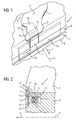
- FIG. 1 shows a safety device 1.
- the rotor has a blade groove 4.
- This blade groove 4 may be a blade groove 4 formed parallel to a rotation axis 5 of the rotor.
- the blade groove 4 may also be a curved blade groove 4, which is then arranged at a front edge in the axial direction 7.
- the rotation axis 5 and the axial direction 7 are arranged parallel to each other.
- the rotor 2 rotates about the rotation axis 5 at a rotational speed.
- the turbine blade is adapted in the blade groove 4, so that as little clearance as possible arises between the turbine blade root 3 and the blade groove 4. Without safety device 8, the turbine blade could be moved freely in the axial direction 7.
- the rotor 2 and the turbine blade may be part of a turbomachine, for example a steam turbine.
- a turbomachine for example a steam turbine.
- the centrifugal forces are still comparatively low, during transport, no centrifugal forces are present. Thereby, there is the possibility that the turbine blade can shift in the axial direction 7.
- a safety device 8 From a certain rotational frequency, the centrifugal forces are so great that the turbine blade presses in the blade groove 4 against so-called support flanks 9, thereby obtaining a stable position. From this particular rotational frequency, axial displacement is difficult to achieve.
- the securing device 8 is a displacement of the turbine blade effectively prevented in the axial 7 and radial directions.
- the securing device 8 comprises a holding piece 10
- FIGS. 1 to 5 show a first embodiment of the holding piece 10.
- the holding piece 10 is disposed between the blade groove 4 and the turbine blade root 3.
- the holding piece 10 comprises a front side 11, which is arranged on the front edge 6.
- the holding piece 10 has an upper side 13 and a lower side 14.
- the upper side 13 is arranged opposite the lower side 14.
- the upper side 13 abuts an underside of the turbine blade root 3, as shown in FIG FIG. 2 is shown.
- the front 11 and the front edge 6 are hereby flush.
- the underside 14 of the holding piece 10 points in the direction of the axis of rotation 5.
- the holding piece On the upper side 13, the holding piece on a projection 15 which is elongated in a circumferential direction 16 according to a first variant of the invention.
- the projection 15 has a rectangular cross-section.
- the projection 15 is formed over the entire top 13 and protrudes into a recess 17 in the turbine blade root 3.
- the recess 17 is in this case formed complementary to the projection 15. That is, the recess 17 also has an elongated shape and a rectangular cross section.
- a displacement of the holding piece, when the projection is arranged in the recess 17, in the axial direction 7 is no longer possible, so that a displacement of the holding piece 10 in the axial direction 7 is prevented.
- the securing device 10 has a metal sheet 19, which engages in a rotor recess 20 and in a second recess 21, so that a displacement of the plate 19 in the axial direction 7 is prevented.
- the second recess 21 is arranged in the holding piece 10. The sheet 19 is thereby inserted from the side.
- the sheet 19 is shaped so as to face in the circumferential direction 16.
- FIG. 2 shows a cross-sectional view of this first variant of the holding piece 10 and the entire safety device 8.
- Die FIGS. 3 and 4 show a perspective view of the holding piece 10 in its first variant.
- the FIG. 5 shows the sheet 19, which is formed in a circumferential direction 16.
- the sheet has a top sheet 22 which projects into the second recess 21.
- the sheet bottom 23 protrudes into the rotor recess 20th
- FIGS. 6 to 9 show a second variant of the securing device. 8
- the difference of the securing device 8 according to the second variant with respect to the securing device 8 of the first variant is that the projection 15 is not elongated, but is designed as a cylinder 24 and projects into a blind hole in the turbine blade root 3.
- the cylinder 24 in this case has a similar mode of action as the projection 15 according to FIG. 1, namely that displacement in the axial direction 7 is prevented.
- FIGS. 7 and 8 show a perspective view of the holding piece 10 according to variant 2.
- FIG. 9 shows the plate 19, which is designed for the variant 2, wherein the sheet 19 according to variant 1 and variant 3 is identical.
- the sheet 19 is arranged circumferentially in the circumferential direction 16 and is executed here segmented. This means that the sheet 19 consists of individual segments.
- the sheet 19 is positively arranged in the rotor recess 20 and in the second recess.
- the plates 19 are inserted via a milled opening of the circumferential groove to a circumferential position and pushed to its final position, after insertion of the last segment, the segments are connected to each other at the pitches by spot welding.
- the force spring 18 serves to ensure the installation of the turbine blade to the rotor 2 at a standstill, z. B. during transport.
- the power spring 18 is formed for example as a plate spring. But the spring 18 can also be performed as a clamping piece.
- FIGS. 10 to 13 show a third variant of the securing device 8.
- the third variant is characterized in that the holding piece 10 and the force spring 18 are arranged side by side in the axial direction 7. This means that the force spring 18 is arranged directly on the rotor 2 and directly on the turbine blade root 3 and the force is transmitted directly from the rotor 2 to the turbine blade root 3.
- the holding piece 10 is arranged in the axial direction 7 next to the force spring 18.
- the holding piece 10 also has a projection 15 and a second recess 21.
- the projection 15 may be elongated according to the first variant. Likewise, the projection 15 may be formed according to the second variant as a cylinder.
- the FIG. 10 shows a cross-sectional view of the securing device 8 according to the third variant.
- the FIGS. 11 and 12 show a perspective view of the holding piece 10. Die FIG. 13 shows a perspective view of the sheet 19th
- FIGS. 14 and 15 show a fourth variant of the securing device 8.
- the safety device 8 according to the fourth variant is characterized in that the holding piece 10 is now formed from the front edge 6 of the turbine blade root 3 to the trailing edge of the turbine blade root. This means that the holding piece 10 is arranged completely from the front edge 6 to the trailing edge.
- the holding piece 10 also has a projection 15 which in a Recess 17 engages.
- a metal plate 19 is likewise provided, which engages in a second recess 21 and in a rotor recess 20.
- the force spring 18 is also arranged between the holding piece 10 and the rotor 2.
Abstract
Die Erfindung betrifft eine Sicherungseinrichtung (2) für eine Turbinenschaufel, die ein radiales und axiales Verschieben der Turbinenschaufel verhindert, wobei die Sicherungseinrichtung (2) sich durch ein Haltestück (10) auszeichnet, das einen Vorsprung (15) aufweist, der in eine Ausnehmung (17) im Turbinenschaufelfuß (3) hineinragt und ein axiales Verschieben verhindert.The invention relates to a securing device (2) for a turbine blade, which prevents a radial and axial displacement of the turbine blade, wherein the securing device (2) is characterized by a holding piece (10) which has a projection (15) which fits into a recess (10). 17) in the turbine blade root (3) protrudes and prevents axial displacement.
Description
Die Erfindung betrifft einen Rotor umfassend zumindest eine Turbinenschaufel und eine Sicherungseinrichtung zur axialen und radialen Sicherung der Turbinenschaufel, wobei der Rotor eine Schaufelnut und die Turbinenschaufel einen Turbinenschaufelfuß umfasst, wobei die Schaufelnut und der Turbinenschaufelfuß an die Schaufelnut angepasst ist, wobei die Sicherungseinrichtung ein Haltestück aufweist, das zwischen der Schaufelnut und dem Turbinenschaufelfuß angeordnet ist.The invention relates to a rotor comprising at least one turbine blade and a securing device for axial and radial securing of the turbine blade, wherein the rotor comprises a blade groove and the turbine blade comprises a turbine blade root, wherein the blade groove and the turbine blade root is adapted to the blade groove, wherein the securing device has a holding piece , which is arranged between the blade groove and the turbine blade root.
Schaufelbefestigungen werden in der Regel zum Befestigen von Laufschaufeln an einem Rotor einer Strömungsmaschine, insbesondere einer Dampfturbine verwendet. Durch die vergleichsweise hohe Rotation des Rotors werden die auf dem Rotor angeordneten Laufschaufeln hohen Fliehkräften ausgesetzt. Der Turbinenschaufelfuß der Turbinenschaufeln muss daher hohen Kräften standhalten und wird in der Schaufelnut radial nach außen gedrängt. Neben den Fliehkräften stellen starke Schwingungsbelastungen ein weiteres Problem dar, die mechanische Beschädigungen, Materialermüdungen zur Folge haben können. Korrosion und eine Wanderbewegung des Schaufelfußes durch die Dmpfbeaufschlagung oder Schwingungen innerhalb der Schaufelnut stellen weitere Probleme dar. Zum Festlegen des Turbinenschaufelfußes innerhalb der Schaufelnut sind verschiedene Lösungen wie beispielsweise Metallkeile, Federringe oder Abdichtungsstücke bekannt. Metallkeile stellen zwar axial als auch radial eine Arretierung des zugehörigen Schaufelfußes innerhalb einer Schaufelnut her, aber bei großen Laufschaufeln ist es mit solchen Metallkeilen schwierig, ausreichende Haltekräfte während der Rotation in radialer Richtung zu erzeugen. Des Weiteren zeigen Metallkeile bei längerem Betrieb im Dampfmedium ein korrosives Verhalten, das die Demontage schwierig macht.Blade fasteners are typically used to secure blades to a rotor of a turbomachine, particularly a steam turbine. Due to the comparatively high rotation of the rotor, the rotor blades arranged on the rotor are exposed to high centrifugal forces. The turbine blade root of the turbine blades must therefore withstand high forces and is urged radially outward in the blade groove. In addition to the centrifugal forces, strong vibration loads pose a further problem, which can result in mechanical damage or material fatigue. Corrosion and migration of the blade root by the steaming or vibrations within the blade groove pose further problems. Various solutions such as metal wedges, spring washers or sealing pieces are known for securing the turbine blade root within the blade groove. While metal wedges provide locking of the associated blade root within a blade groove both axially and radially, with large blades it is difficult with such metal wedges to produce sufficient holding forces during rotation in the radial direction. Furthermore, metal wedges show a corrosive behavior during prolonged operation in the vapor medium, which makes disassembly difficult.
Es sind axial gefädelte Laufschaufeln bekannt, die in Turbomaschinen wie beispielsweise Dampfturbinen, die aufgrund der Betriebsbeanspruchung eine Konstruktion benötigen, die die axialen Betriebskräfte der Turbinenschaufel aufnimmt und die Schaufel in ihrer axialen Position hält. Solche Sicherungen werden auch als axiale Sicherungen bezeichnet. In der Regel werden bei solchen axialen Sicherungen zwei Kerben angeordnet, die zueinander überlagert ausgebildet sind. Allerdings zeigen Überlagerungen von Kerben häufig eine erhöhte Beanspruchung und bedeuten somit eine begrenzte Anwendbarkeit im Turbomaschinenbau.Axially threaded blades are known in turbomachinery, such as steam turbines, which, due to the operating stress, require a design that receives the axial operating forces of the turbine blade and holds the blade in its axial position. Such fuses are also referred to as axial fuses. In general, two notches are arranged in such axial fuses, which are formed superimposed to each other. However, notches of notches often show increased stress and thus have limited applicability in turbomachinery.
Der Erfindung liegt die Aufgabe zugrunde, eine Schaufelbefestigung bei einer Strömungsmaschine bereitzustellen, bei der über einen langen Betriebszeitraum hinweg eine präzise und feste Halterung von Schaufeln, den zugehörigen Schaufelhaltern, sichergestellt ist.The invention has for its object to provide a blade attachment in a turbomachine in which over a long period of operation, a precise and firm support of blades, the associated blade holders, is ensured.
Die Aufgabe wird gelöst durch einen Rotor umfassend zumindest eine Turbinenschaufel und eine Sicherungseinrichtung zur axialen und radialen Sicherung der Turbinenschaufel, wobei der Rotor eine Schaufelnut und die Turbinenschaufel einen Turbinenschaufelfuß umfasst, wobei die Schaufelnut und der Turbinenschaufelfuß an die Schaufelnut angepasst ist, wobei die Sicherungseinrichtung ein Haltestück aufweist, das zwischen der Schaufelnut und dem Turbinenschaufelfuß angeordnet ist, wobei das Haltestück einen Vorsprung aufweist, der in eine Ausnehmung im Turbinenschaufelfuß angeordnet ist, wobei der Vorsprung in die Ausnehmung derart eingreift, dass ein Verschieben des Haltestücks in der axialen Richtung verhindert ist, wobei die Sicherungseinrichtung eine Kraftfeder aufweist, die eine in radialer Richtung wirkende Kraft von dem Rotor auf die Turbinenschaufel ausübt.The object is achieved by a rotor comprising at least one turbine blade and a securing device for axial and radial securing of the turbine blade, wherein the rotor comprises a blade groove and the turbine blade comprises a turbine blade root, wherein the blade groove and the turbine blade root is adapted to the blade groove, wherein the securing device A holding piece, which is arranged between the blade groove and the turbine blade root, wherein the holding piece has a projection which is arranged in a recess in the turbine blade root, wherein the projection engages in the recess such that a displacement of the holding piece in the axial direction is prevented wherein the securing means comprises a force spring exerting a radially acting force from the rotor to the turbine blade.
Mit der Erfindung wird somit vorgeschlagen, in einen Raum zwischen dem Rotor und dem Turbinenschaufelfuß eine Sicherungseinrichtung anzuordnen. Dieser Raum ist vorzugszweise im Rotor angeordnet. Somit wird die durch den Raum gebildete Kerbe in eine radial innere Richtung zur Rotationsachse hin verschoben. Dadurch sind die angreifenden Kräfte auf den Rotor besser verteilt.With the invention it is thus proposed to arrange a securing device in a space between the rotor and the turbine blade root. This space is preferably arranged in the rotor. Thus, the formed by the space Notch in a radially inner direction to the axis of rotation shifted. As a result, the forces acting on the rotor are better distributed.
Vorteilhafte Weiterbildungen sind in den Unteransprüchen angegeben.Advantageous developments are specified in the subclaims.
In einer Weiterbildung ist das Haltestück direkt in den Schaufelfuß integriert. Hierbei ist dies in axialer Richtung gesehen wahlweise an der Vorderkante des Schaufelfußes oder bevorzugterweise an der Hinterkante des Schaufelfußes in die radial innere Richtung ausgeprägt. Eine Ausprägung an der Vorderkante und Hinterkante ist hier möglich bei der Umsetzung einer axialen Ausnehmung, die das axiale Einschieben der modifizierten Schaufel weiterhin ermöglicht.In a development, the holding piece is integrated directly into the blade root. This is seen in the axial direction optionally pronounced on the leading edge of the blade root or preferably at the trailing edge of the blade root in the radially inner direction. An expression on the leading edge and trailing edge is possible here in the implementation of an axial recess, which further allows the axial insertion of the modified blade.
In einer ersten vorteilhaften Weiterbildung weist die Sicherungseinrichtung ein Blech auf, das in einer zweiten Ausnehmung im Haltestück und in einer Rotorausnehmung angeordnet ist, wobei das Blech in die zweite Ausnehmung und in die Rotorausnehmung derart eingreift, dass ein Verschieben des Blechs in der axialen Richtung verhindert ist.In a first advantageous development, the securing device has a metal sheet which is arranged in a second recess in the holding piece and in a rotor recess, wherein the sheet engages in the second recess and in the rotor recess in such a way that prevents displacement of the sheet in the axial direction is.
Somit wird ein wirksames Verschieben in axialer Richtung des Haltestücks wirksam vermieden. Das Blech wird hierbei in eine Rotorausnehmung und in eine zweite Ausnehmung im Haltestück angeordnet und bildet somit eine Sperre für das Haltestück um in axialer Richtung verschoben werden zu können.Thus, an effective displacement in the axial direction of the holding piece is effectively avoided. The sheet is in this case arranged in a rotor recess and in a second recess in the holding piece and thus forms a barrier for the holding piece to be moved in the axial direction can.
In einer vorteilhaften Weiterbildung ist zwischen der Schaufelnut und dem Haltestück eine Kraftfeder anordnet.In an advantageous development, a force spring is arranged between the blade groove and the holding piece.
Mit dieser Kraftfeder wird eine Kraft von dem Rotor auf den Turbinenschaufelfuß ausgeübt. Beim Transport sowie im Betrieb ist es wichtig, gerade bei niedrigen Rotationsgeschwindigkeiten eine Kraft auf den Turbinenschaufelfuß auszuüben, der in einer radialen Richtung wirkt. Dadurch ist ein Verschieben der Turbinenschaufel in axialer Richtung durch Reibungseffekte weiter vermieden. Ab einer bestimmten Rotationsgeschwindigkeit sind in radialer Richtung auf die Turbinenschaufel wirkende Fliehkräfte so groß, dass der Einfluss der Federkraft durch die Kraftfeder zu vernachlässigen ist.With this force spring, a force is exerted by the rotor on the turbine blade root. During transport, as well as during operation, it is important to exert a force on the turbine blade root, which acts in a radial direction, especially at low rotational speeds. This is a displacement of the turbine blade in the axial direction by friction effects further avoided. From a certain rotational speed centrifugal forces acting on the turbine blade in the radial direction are so great that the influence of the spring force by the force spring is negligible.
Vorteilhafterweise ist die Kraftfeder neben dem Haltestück zwischen der Schaufelnut und dem Schaufelfuß angeordnet.Advantageously, the force spring is arranged next to the holding piece between the blade groove and the blade root.
Dies ist eine besonders einfache und konstruktive Lösung, die durch einfache Mittel herstellbar ist.This is a particularly simple and constructive solution that can be produced by simple means.
In einer weiteren vorteilhaften Weiterbildung weist der Schaufelfuß eine in axialer Richtung gesehen angeordnete Vorderkante und in der axialen Richtung gesehen zur Vorderkante gegenüber angeordnete Hinterkante auf, wobei das Haltestück von der Vorderkante bis zur Hinterkante ragt.In a further advantageous development, the blade root has a front edge arranged in the axial direction and a trailing edge arranged opposite the front edge in the axial direction, wherein the retaining piece protrudes from the front edge to the rear edge.
Hierbei wird nun erfindungsgemäß vorteilhafterweise vorgeschlagen, das Haltestück derart weiterzubilden, dass die Ausmaße in axialer Richtung derart sind, dass das Haltestück von der Vorderkante bis zur Hinterkante ragt.In this case, it is advantageously proposed according to the invention to further develop the retaining piece in such a way that the dimensions in the axial direction are such that the retaining piece protrudes from the front edge to the trailing edge.
In einer weiteren vorteilhaften Weiterbildung ist ein erstes Sicherungsblech an der Vorderkante und ein zweites Sicherungsblech an der Hinterkante angeordnet.In a further advantageous development, a first locking plate is arranged on the front edge and a second locking plate on the trailing edge.
Dadurch wird ein Verschieben in axialer Richtung des Haltestückes sowohl in die eine axiale Richtung als auch in die entgegengesetzt zeigende axiale Richtung wirksam verhindert.Thereby, a displacement in the axial direction of the holding piece is effectively prevented both in the one axial direction and in the opposite pointing axial direction.
In einer weiteren vorteilhaften Weiterbildung ist eine erste Kraftfeder an der Vorderkante und eine zweite Kraftfeder an der Hinterkante angeordnet.In a further advantageous development, a first force spring is arranged on the front edge and a second force spring on the rear edge.
Dadurch können symmetrische Verteilungen von Kräften und Schwingungen weiter minimiert werden, die insbesondere beim Anfahren oder beim Transport auftreten.As a result, symmetrical distributions of forces and vibrations can be further minimized, which occur in particular during startup or during transport.
In einer weiteren vorteilhaften Weiterbildung ist der Vorsprung in Umfangsrichtung (bezogen auf die Rotationsachse) länglich ausgebildet.In a further advantageous development of the projection in the circumferential direction (relative to the axis of rotation) is elongate.
Eine längliche Ausbildung ist in der Regel ein vergleichsweise einfaches Herstellungsverfahren, was hier zu einer Kostenersparnis führen wird.An elongated design is usually a relatively simple manufacturing process, which will lead to a cost savings here.
Vorteilhafterweise weist der Vorsprung einen rechtwinkligen Querschnitt auf.Advantageously, the projection has a rectangular cross-section.
In einer weiteren vorteilhaften Weiterbildung ist der Vorsprung als Zylinder ausgeführt und greift in eine als Sacklochbohrung ausgebildete Ausnehmung auf. Dies stellt eine Alternative zu der länglich ausgebildeten Form des Vorsprungs dar. Auf die hier vorteilhafterweise vorgeschlagene Sacklockbohrung, in der der als Vorsprung ausgebildete Zylinder eingreift, wirkt eine punktuell eingreifende Kraft.In a further advantageous embodiment, the projection is designed as a cylinder and engages in a recess formed as a blind hole. This represents an alternative to the elongated shape of the projection. The here advantageously proposed Sacklockbohrung in which engages formed as a projection cylinder acts a punctually engaging force.
Vorteilhafterweise sind die Rotorausnehmung und die zweite Ausnehmung in radialer Richtung übereinander angeordnet.Advantageously, the rotor recess and the second recess are arranged one above the other in the radial direction.
Durch die in radialer Richtung übereinander angeordnete Ausrichtung ist ein Verkippen des Blechs wirksam vermieden. Die oben beschriebenen Eigenschafen, Merkmale und Vorteile dieser Erfindung sowie die Art und Weise, wie diese erreicht werden, werden klarer und deutlicher verständlich im Zusammenhang mit der folgenden Beschreibung der Ausführungsbeispiele, die im Zusammenhang mit den Zeichnungen näher erläutert werden.By aligned in the radial direction alignment tilting of the sheet is effectively avoided. The above-described characteristics, features, and advantages of this invention, as well as the manner in which they will be achieved, will become clearer and more clearly understood in connection with the following description of the embodiments, which will be described in connection with the drawings.
Ausführungsbeispiele der Erfindung werden nachfolgend anhand der Zeichnungen beschrieben. Diese sollen die Ausführungsbeispiele nicht maßgeblich darstellen, vielmehr ist die Zeichnung, wozu Erläuterungen dienlich, in schematisierter und/oder leicht verzehrter Form ausgeführt. Im Hinblick auf Ergänzungen der in der Zeichnung unmittelbar erkennbaren Lehren wird auf den einschlägigen Stand der Technik verwiesen.Embodiments of the invention will be described below with reference to the drawings. These are not intended to represent the embodiments significantly, but the drawing, including explanations useful, executed in a schematized and / or slightly consumed form. With regard to additions to the teachings directly recognizable in the drawing reference is made to the relevant prior art.
Es zeigen:
- Figur 1
- eine perspektivische Ansicht einer Sicherungseinrichtung,
Figur 2- eine Querschnittsansicht einer ersten Variante der Sicherungseinrichtung,
Figur 3- eine perspektivische Darstellung des Haltestücks gemäß der ersten Variante aus
Figur 2 Figur 4- eine weitere perspektivische Darstellung des Haltestücks aus
Figur 3 Figur 5- eine perspektivische Darstellung eines Blechs,
Figur 6- eine Querschnittsansicht einer Sicherungseinrichtung gemäß einer zweiten Variante,
Figur 7- eine perspektivische Darstellung des Haltestücks gemäß der zweiten Variante aus
Figur 6 Figur 8- eine weitere perspektivische Darstellung des Haltestücks aus
Figur 7 , Figur 9- eine perspektivische Darstellung des Blechs,
Figur 10- eine Querschnittsansicht einer Sicherungseinrichtung gemäß einer dritten Variante,
Figur 11- eine perspektivische Ansicht des Haltestücks gemäß der dritten Variante,
Figur 12- eine weitere perspektivische Ansicht des haltestücks gemäß
Figur 11 für die dritte Variante, Figur 13- Darstellung des Blechs für die dritte Variante,
Figur 14- Querschnittsansicht der Sicherungseinrichtung gemäß einer vierten Variante,
Figur 15- Querschnittsansicht eines Teils der Sicherungseinrichtung gemäß der vierten Variante.
- FIG. 1
- a perspective view of a safety device,
- FIG. 2
- a cross-sectional view of a first variant of the securing device,
- FIG. 3
- a perspective view of the holding piece according to the first variant
FIG. 2 . - FIG. 4
- another perspective view of the holding piece
FIG. 3 . - FIG. 5
- a perspective view of a sheet,
- FIG. 6
- a cross-sectional view of a securing device according to a second variant,
- FIG. 7
- a perspective view of the holding piece according to the second variant
FIG. 6 . - FIG. 8
- another perspective view of the holding piece
FIG. 7 . - FIG. 9
- a perspective view of the sheet,
- FIG. 10
- a cross-sectional view of a securing device according to a third variant,
- FIG. 11
- a perspective view of the holding piece according to the third variant,
- FIG. 12
- another perspective view of the retaining piece according to
FIG. 11 for the third variant, - FIG. 13
- Representation of the sheet for the third variant,
- FIG. 14
- Cross-sectional view of the securing device according to a fourth variant,
- FIG. 15
- Cross-sectional view of a part of the securing device according to the fourth variant.
Die Rotationsachse 5 und die axiale Richtung 7 sind parallel zueinander angeordnet. Der Rotor 2 rotiert um die Rotationsachse 5 mit einer Drehgeschwindigkeit. Die Turbinenschaufel ist in der Schaufelnut 4 angepasst, so dass möglichst wenig Spielraum zwischen dem Turbinenschaufelfuß 3 und der Schaufelnut 4 entsteht. Ohne Sicherungseinrichtung 8 könnte die Turbinenschaufel in der axialen Richtung 7 frei verschoben werden.The
Der Rotor 2 und die Turbinenschaufel können Teil einer Turbomaschine, beispielsweise einer Dampfturbine sein. Während des Anfahrens einer Strömungsmaschine sind die Fliehkräfte noch vergleichsweise gering, beim Transport sind keinerlei Fliehkräfte vorhanden. Dadurch besteht die Möglichkeit, dass die Turbinenschaufel sich in der axialen Richtung 7 verschieben kann. Dies wird verhindert durch eine Sicherungseinrichtung 8. Ab einer gewissen Rotationsfrequenz sind die Fliehkräfte derart groß, dass die Turbinenschaufel in der Schaufelnut 4 gegen sogenannte Tragflanken 9 drückt und dadurch eine stabile Position erhält. Ab dieser bestimmten Rotationsfrequenz ist ein axiales Verschieben schwer möglich. Mit der Sicherungseinrichtung 8 ist ein Verschieben der Turbinenschaufel in axialer 7 und radialer Richtung wirksam verhindert. Die Sicherungseinrichtung 8 umfasst ein Haltestück 10. Die
Auf der Oberseite 13 weist das Haltestück einen Vorsprung 15 auf, der gemäß einer ersten Variante der Erfindung in einer Umfangsrichtung 16 länglich ausgebildet ist. Der Vorsprung 15 weist einen rechtwinkligen Querschnitt auf. Der Vorsprung 15 ist über die komplette Oberseite 13 ausgebildet und ragt in eine Ausnehmung 17 im Turbinenschaufelfuß 3. Die Ausnehmung 17 ist hierbei komplementär zum Vorsprung 15 ausgebildet. Das bedeutet, dass die Ausnehmung 17 ebenso eine längliche Form und einen rechtwinkligen Querschnitt aufweist.On the
Ein Verschieben des Haltestücks ist, wenn der Vorsprung in der Ausnehmung 17 angeordnet ist, in axialer Richtung 7 nicht mehr möglich, so dass ein Verschieben des Haltestücks 10 in der axialen Richtung 7 verhindert ist.A displacement of the holding piece, when the projection is arranged in the
Wie in
Die
Die
Der Unterschied der Sicherungseinrichtung 8 gemäß der zweiten Variante gegenüber der Sicherungseinrichtung 8 der ersten Variante ist, dass der Vorsprung 15 nicht länglich ausgebildet ist, sondern als Zylinder 24 ausgeführt ist und in eine Sacklochbohrung im Turbinenschaufelfuß 3 hineinragt. Der Zylinder 24 hat hierbei eine ähnliche Wirkungsweise wie der Vorsprung 15 gemäß 1, nämlich dass ein Verschieben in axialer Richtung 7 verhindert wird.The difference of the securing
Die
Die
Das Blech 19 ist in Umfangsrichtung 16 umlaufend angeordnet und ist hierbei segmentiert ausgeführt. Das bedeutet, dass das Blech 19 aus einzelnen Segmenten besteht. Das Blech 19 ist formschlüssig in der Rotorausnehmung 20 und in der zweiten Ausnehmung angeordnet. Die Bleche 19 werden über eine angefräste Öffnung der umlaufenden Nut an eine Umfangsposition eingeführt und an ihre finale Position geschoben, nach Einführen des letzten Segmentes werden die Segmente an den Teilungen miteinander durch Punktschweißung verbunden. Die Kraftfeder 18 dient zur Sicherstellung der Anlage der Turbinenschaufel an den Rotor 2 unter Stillstand, z. B. während des Transportes. Die Kraftfeder 18 ist beispielsweise als Tellerfeder ausgebildet. Die Kraftfeder 18 kann aber ebenso auch als Klemmstück ausgeführt werden.The
Die
Die
Obwohl die Erfindung im Detail durch das bevorzugte Ausführungsbeispiel näher illustriert und beschrieben wurde, so ist die Erfindung nicht durch die offenbarten Beispiele eingeschränkt und andere Variationen können vom Fachmann hieraus abgeleitet werden, ohne den Schutzumfang der Erfindung zu verlassen.Although the invention has been further illustrated and described in detail by the preferred embodiment, the invention is not limited by the disclosed examples, and other variations can be derived therefrom by those skilled in the art without departing from the scope of the invention.
Claims (15)
zumindest eine Turbinenschaufel
und eine Sicherungseinrichtung (1) zur axialen und radialen Sicherung der Turbinenschaufel,
wobei der Rotor (2) eine Schaufelnut (4) und
die Turbinenschaufel einen Turbinenschaufelfuß (3) umfasst,
wobei die Schaufelnut (4) und der Turbinenschaufelfuß (3) an die Schaufelnut (4) angepasst ist,
wobei die Sicherungseinrichtung (1) ein Haltestück (10) aufweist,
das zwischen der Schaufelnut (4) und dem Turbinenschaufelfuß (3) angeordnet ist,
wobei das Haltestück (10) einen Vorsprung (15) aufweist, der in eine Ausnehmung (17) im Turbinenschaufelfuß (4) angeordnet ist, wobei der Vorsprung (15) in die Ausnehmung (17) derart eingreift, dass ein Verschieben des Haltestücks (10) in der axialen Richtung (7) verhindert ist,
wobei die Sicherungseinrichtung (1) eine Kraftfeder (18) aufweist, die eine in radialer Richtung wirkende Kraft von dem Rotor (2) auf die Turbinenschaufel ausübt.Comprising rotor (2)
at least one turbine blade
and a securing device (1) for axial and radial securing of the turbine blade,
wherein the rotor (2) has a blade groove (4) and
the turbine blade comprises a turbine blade root (3),
wherein the blade groove (4) and the turbine blade root (3) are adapted to the blade groove (4),
wherein the securing device (1) has a holding piece (10),
which is arranged between the blade groove (4) and the turbine blade root (3),
wherein the holding piece (10) has a projection (15) which is arranged in a recess (17) in the turbine blade root (4), wherein the projection (15) engages in the recess (17) such that a displacement of the holding piece (10 ) is prevented in the axial direction (7),
wherein the securing means (1) comprises a force spring (18) which exerts a radially acting force from the rotor (2) on the turbine blade.
wobei die Sicherungseinrichtung (1) ein Blech (19) aufweist,
dass in eine zweite Ausnehmung (21) im Haltestück (10) und in einer Rotorausnehmung (20) angeordnet ist,
wobei das Blech (19) in eine zweite Ausnehmung (21) und in eine Rotationsausnehmung (20) derart eingreift, dass ein Verschieben des Blechs (19) in der axialen Richtung (7) verhindert ist.Rotor (2) according to claim 1,
wherein the securing device (1) has a plate (19),
that in a second recess (21) in the holding piece (10) and in a rotor recess (20) is arranged,
wherein the plate (19) engages in a second recess (21) and in a rotational recess (20) such that a displacement of the sheet (19) in the axial direction (7) is prevented.
wobei die Kraftfeder (18) zwischen der Schaufelnut (4) und dem Haltestück (10) angeordnet ist.Rotor according to claim 1 or 2,
wherein the force spring (18) between the blade groove (4) and the holding piece (10) is arranged.
wobei die Kraftfeder (18) neben dem Haltestück (10) zwischen der Schaufelnut (4) und dem Schaufelfuß (3) angeordnet ist.Rotor (2) according to claim 1 or 2,
wherein the force spring (18) adjacent to the holding piece (10) between the blade groove (4) and the blade root (3) is arranged.
wobei der Schaufelfuß (3) eine in axialer Richtung (7) gesehen angeordnete Vorderkante (6) und in der axialen Richtung (7) gesehen zur Vorderkante (6) gegenüber angeordnete Hinterkante ausweist,
wobei das Haltestück (10) von der Vorderkante (6) bis zur Hinterkante ragt.Rotor (2) according to one of the preceding claims,
the blade root (3) having a front edge (6) arranged in the axial direction (7) and a trailing edge facing the front edge (6) in the axial direction (7),
wherein the holding piece (10) protrudes from the front edge (6) to the trailing edge.
wobei ein erstes Sicherungsblech an der Vorderkante (6) und ein zweites Sicherungsblech an der Hinterkante angeordnet ist.Rotor (2) according to claim 5,
wherein a first locking plate at the front edge (6) and a second locking plate is arranged at the trailing edge.
wobei eine erste Kraftfeder (18) an der Vorderkante (6) und eine zweite Kraftfeder an der Hinterkante angeordnet ist.Rotor (2) according to claim 5 or 6,
wherein a first force spring (18) is arranged on the front edge (6) and a second force spring on the trailing edge.
wobei der Vorsprung (15) in einer zu der Rotationsachse (5) des Rotors (2) orientierten Umfangsrichtung länglich ausgebildet ist.Rotor (2) according to one of the preceding claims,
wherein the projection (15) is elongated in a circumferential direction oriented with respect to the rotation axis (5) of the rotor (2).
wobei der Vorsprung (15) einen rechtwinkligen Querschnitt aufweist.Rotor (2) according to claim 1,
wherein the projection (15) has a rectangular cross-section.
wobei der Vorsprung (15) als Zylinder (24) ausgeführt ist und in die als Sackloch-Bohrung (25) ausgebildete Ausnehmung eingreift.Rotor according to one of claims 1 to 7,
wherein the projection (15) is designed as a cylinder (24) and engages in the formed as a blind hole (25) recess.
wobei die Rotorausnehmung (20) und die zweite Ausnehmung (21) in radialer Richtung übereinander angeordnet sind.Rotor (2) according to one of the preceding claims,
wherein the rotor recess (20) and the second recess (21) are arranged one above the other in the radial direction.
wobei die Sicherungseinrichtung (1) in einer Einrichtungs-Ausnehmung im Rotor (2) angeordnet ist.Rotor (2) according to one of the preceding claims,
wherein the securing device (1) is arranged in a device recess in the rotor (2).
wobei eine erste Einrichtungs-Ausnehmung an der Vorderkante (11) und eine zweite Einrichtungs-Ausnehmung an der Hinterkante ausgebildet ist.Rotor according to claim 12,
wherein a first device recess is formed on the front edge (11) and a second device recess on the rear edge.
wobei die Kraftfeder (18) als Tellerfeder ausgebildet ist.Rotor (2) according to one of the preceding claims,
wherein the force spring (18) is designed as a plate spring.
wobei das Haltestück (10) Teil des Turbinenschaufelfußes (3) ist.Rotor (2) according to one of the preceding claims,
wherein the holding piece (10) is part of the turbine blade root (3).
Priority Applications (8)
| Application Number | Priority Date | Filing Date | Title |
|---|---|---|---|
| EP15151806.5A EP3048256A1 (en) | 2015-01-20 | 2015-01-20 | Rotor comprising a turbine blade with a locking device |
| PCT/EP2016/050066 WO2016116285A1 (en) | 2015-01-20 | 2016-01-05 | Blade fastening mechanism having a securing device for turbine blades |
| KR1020177023020A KR101942209B1 (en) | 2015-01-20 | 2016-01-05 | Blade fastening mechanism with fasteners for turbine blades |
| RU2017129253A RU2668512C1 (en) | 2015-01-20 | 2016-01-05 | Fixing blades with safety device for turbine blades |
| CN201680006607.8A CN107208490B (en) | 2015-01-20 | 2016-01-05 | The fixed device of blade with the locking device for turbo blade |
| US15/542,510 US10487674B2 (en) | 2015-01-20 | 2016-01-05 | Blade fastening mechanism having a securing device for turbine blades |
| EP16700042.1A EP3212895B1 (en) | 2015-01-20 | 2016-01-05 | Rotor comprising a turbine blade with a locking device |
| JP2017555832A JP6527959B2 (en) | 2015-01-20 | 2016-01-05 | Blade fastening mechanism with fastening device for a turbine blade |
Applications Claiming Priority (1)
| Application Number | Priority Date | Filing Date | Title |
|---|---|---|---|
| EP15151806.5A EP3048256A1 (en) | 2015-01-20 | 2015-01-20 | Rotor comprising a turbine blade with a locking device |
Publications (1)
| Publication Number | Publication Date |
|---|---|
| EP3048256A1 true EP3048256A1 (en) | 2016-07-27 |
Family
ID=52358662
Family Applications (2)
| Application Number | Title | Priority Date | Filing Date |
|---|---|---|---|
| EP15151806.5A Withdrawn EP3048256A1 (en) | 2015-01-20 | 2015-01-20 | Rotor comprising a turbine blade with a locking device |
| EP16700042.1A Active EP3212895B1 (en) | 2015-01-20 | 2016-01-05 | Rotor comprising a turbine blade with a locking device |
Family Applications After (1)
| Application Number | Title | Priority Date | Filing Date |
|---|---|---|---|
| EP16700042.1A Active EP3212895B1 (en) | 2015-01-20 | 2016-01-05 | Rotor comprising a turbine blade with a locking device |
Country Status (7)
| Country | Link |
|---|---|
| US (1) | US10487674B2 (en) |
| EP (2) | EP3048256A1 (en) |
| JP (1) | JP6527959B2 (en) |
| KR (1) | KR101942209B1 (en) |
| CN (1) | CN107208490B (en) |
| RU (1) | RU2668512C1 (en) |
| WO (1) | WO2016116285A1 (en) |
Cited By (1)
| Publication number | Priority date | Publication date | Assignee | Title |
|---|---|---|---|---|
| FR3070423A1 (en) * | 2017-08-22 | 2019-03-01 | Safran Aircraft Engines | DAGGER ATTACHMENT WITH SEAL AND SPRING OF A DRAWER |
Families Citing this family (6)
| Publication number | Priority date | Publication date | Assignee | Title |
|---|---|---|---|---|
| IT201600130088A1 (en) * | 2016-12-22 | 2018-06-22 | Nuovo Pignone Tecnologie Srl | Turbine blade and fastening set |
| KR102236266B1 (en) | 2017-11-17 | 2021-04-05 | 한화에어로스페이스 주식회사 | Rotating apparatus |
| DE102019210647A1 (en) * | 2019-07-18 | 2021-01-21 | Siemens Energy Global GmbH & Co. KG | Blade ring for an axial turbo machine |
| KR102454379B1 (en) * | 2020-09-08 | 2022-10-14 | 두산에너빌리티 주식회사 | rotor and turbo-machine comprising the same |
| US11208903B1 (en) * | 2020-11-20 | 2021-12-28 | Solar Turbines Incorporated | Stiffness coupling and vibration damping for turbine blade shroud |
| KR102478172B1 (en) * | 2021-02-02 | 2022-12-14 | 두산에너빌리티 주식회사 | Rotary machine, gas turbine including the same, assembling method of the same |
Citations (4)
| Publication number | Priority date | Publication date | Assignee | Title |
|---|---|---|---|---|
| US2847187A (en) * | 1955-01-21 | 1958-08-12 | United Aircraft Corp | Blade locking means |
| US4668167A (en) * | 1985-08-08 | 1987-05-26 | Societe National D'etude Et De Construction De Moteurs D'aviation "S.N.E.C.M.A." | Multifunction labyrinth seal support disk for a turbojet engine rotor |
| US5431543A (en) * | 1994-05-02 | 1995-07-11 | Westinghouse Elec Corp. | Turbine blade locking assembly |
| EP2299060A1 (en) * | 2009-09-17 | 2011-03-23 | Siemens Aktiengesellschaft | Blade fixation with locking device for turbine blades |
Family Cites Families (8)
| Publication number | Priority date | Publication date | Assignee | Title |
|---|---|---|---|---|
| US3853425A (en) * | 1973-09-07 | 1974-12-10 | Westinghouse Electric Corp | Turbine rotor blade cooling and sealing system |
| JPS6469702A (en) | 1987-09-09 | 1989-03-15 | Hitachi Ltd | Fixation of movable blade of axial flow rotary machine |
| JPH01237304A (en) | 1988-03-15 | 1989-09-21 | Toshiba Corp | Steam turbine bucket pushing-up device |
| US5236309A (en) | 1991-04-29 | 1993-08-17 | Westinghouse Electric Corp. | Turbine blade assembly |
| FR2807096B1 (en) * | 2000-03-30 | 2002-05-31 | Abb Alstom Power Nv | ROTOR DISC OF TURBINE EQUIPPED WITH FINS ON FOOT AND TREE OF MOUNTING A FIN ON A DISC |
| EP1892380A1 (en) * | 2006-08-25 | 2008-02-27 | Siemens Aktiengesellschaft | Turbine blade retention system |
| EP1978211A1 (en) | 2007-04-04 | 2008-10-08 | Siemens Aktiengesellschaft | Assembly for axial protection on rotor blades in a rotor and gas turbine with such an assembly |
| JP5692994B2 (en) | 2009-12-08 | 2015-04-01 | 三菱重工業株式会社 | Rotor blade fixing structure, rotating machine having the same, and rotor blade attaching / detaching method |
-
2015
- 2015-01-20 EP EP15151806.5A patent/EP3048256A1/en not_active Withdrawn
-
2016
- 2016-01-05 EP EP16700042.1A patent/EP3212895B1/en active Active
- 2016-01-05 US US15/542,510 patent/US10487674B2/en active Active
- 2016-01-05 RU RU2017129253A patent/RU2668512C1/en active
- 2016-01-05 WO PCT/EP2016/050066 patent/WO2016116285A1/en active Application Filing
- 2016-01-05 CN CN201680006607.8A patent/CN107208490B/en active Active
- 2016-01-05 JP JP2017555832A patent/JP6527959B2/en active Active
- 2016-01-05 KR KR1020177023020A patent/KR101942209B1/en active IP Right Grant
Patent Citations (4)
| Publication number | Priority date | Publication date | Assignee | Title |
|---|---|---|---|---|
| US2847187A (en) * | 1955-01-21 | 1958-08-12 | United Aircraft Corp | Blade locking means |
| US4668167A (en) * | 1985-08-08 | 1987-05-26 | Societe National D'etude Et De Construction De Moteurs D'aviation "S.N.E.C.M.A." | Multifunction labyrinth seal support disk for a turbojet engine rotor |
| US5431543A (en) * | 1994-05-02 | 1995-07-11 | Westinghouse Elec Corp. | Turbine blade locking assembly |
| EP2299060A1 (en) * | 2009-09-17 | 2011-03-23 | Siemens Aktiengesellschaft | Blade fixation with locking device for turbine blades |
Cited By (1)
| Publication number | Priority date | Publication date | Assignee | Title |
|---|---|---|---|---|
| FR3070423A1 (en) * | 2017-08-22 | 2019-03-01 | Safran Aircraft Engines | DAGGER ATTACHMENT WITH SEAL AND SPRING OF A DRAWER |
Also Published As
| Publication number | Publication date |
|---|---|
| EP3212895B1 (en) | 2021-03-17 |
| CN107208490B (en) | 2019-08-06 |
| US20180266259A1 (en) | 2018-09-20 |
| KR101942209B1 (en) | 2019-01-24 |
| EP3212895A1 (en) | 2017-09-06 |
| US10487674B2 (en) | 2019-11-26 |
| JP2018505994A (en) | 2018-03-01 |
| WO2016116285A1 (en) | 2016-07-28 |
| JP6527959B2 (en) | 2019-06-12 |
| RU2668512C1 (en) | 2018-10-01 |
| CN107208490A (en) | 2017-09-26 |
| KR20170103010A (en) | 2017-09-12 |
Similar Documents
| Publication | Publication Date | Title |
|---|---|---|
| EP3212895B1 (en) | Rotor comprising a turbine blade with a locking device | |
| EP2076656B1 (en) | Blade fastening means of a turbine | |
| EP2478187B1 (en) | Blade fixation with locking device for turbine blades | |
| EP1899581A1 (en) | Turbine rotor and method for the production thereof | |
| DE1426806A1 (en) | Wing body group | |
| CH698337B1 (en) | Arrangement with a mounting system to mount two machine components. | |
| CH652456A5 (en) | HEAD FLANGE FASTENING DEVICE FOR A TURBO MACHINE. | |
| EP2378065A2 (en) | Method for repairing a rotor assembly of a turbo engine, ring element for a rotor assembly of a turbo engine and rotor assembly for a turbo engine | |
| EP2066871B1 (en) | Securing apparatus of a turbine blade | |
| EP3287608B1 (en) | Internal ring for a guide- blade rim of a turbomachine | |
| EP2019188A1 (en) | Rotor stage with damping element | |
| DE102008048261B4 (en) | Axial turbomachinery rotor with a paddle lock and method of making the same | |
| EP3230559B1 (en) | Final module to lock a bladed ring, corresponding blade carrier, turbomachine and method for inserting a final module | |
| EP2098687A1 (en) | Rotor for a turbo engine | |
| DE102017121653B4 (en) | Flange bearing with latches aligned parallel to each other | |
| WO2014044653A1 (en) | Device for overcoming play | |
| EP3172409B1 (en) | Wheel disk assembly having sealing plates | |
| AT525718B1 (en) | rotor | |
| EP1707747A1 (en) | Blade root fixation device and corresponding mounting method | |
| EP1707743A1 (en) | Segment with minimum two blades, turbine element and method to mount a segment | |
| DE19925774A1 (en) | Rotor blades securement unit for axial-flow turbo-machine fits in radial space in axial grooves of rotor disc and is secured to blade foot and rotor by radially aligned sections of securing plate | |
| DE102016219837A1 (en) | Rotor and method of assembling blades using narrower blade platforms | |
| WO2023020655A1 (en) | Adjustable guide vane for a gas turbine, gas turbine and method for assembling an adjustable guide vane for a gas turbine | |
| DE102014215623A1 (en) | Rolling, in particular needle roller bearings, for arrangement on a pivot of a variable guide vane of a turbomachine | |
| DE1115992B (en) | Protection against axial displacement of rotor blades with a fir tree base on gas turbines |
Legal Events
| Date | Code | Title | Description |
|---|---|---|---|
| PUAI | Public reference made under article 153(3) epc to a published international application that has entered the european phase |
Free format text: ORIGINAL CODE: 0009012 |
|
| AK | Designated contracting states |
Kind code of ref document: A1 Designated state(s): AL AT BE BG CH CY CZ DE DK EE ES FI FR GB GR HR HU IE IS IT LI LT LU LV MC MK MT NL NO PL PT RO RS SE SI SK SM TR |
|
| AX | Request for extension of the european patent |
Extension state: BA ME |
|
| STAA | Information on the status of an ep patent application or granted ep patent |
Free format text: STATUS: THE APPLICATION IS DEEMED TO BE WITHDRAWN |
|
| 18D | Application deemed to be withdrawn |
Effective date: 20170128 |