EP3047981A1 - Motorcycle tire for traveling on rough terrain - Google Patents
Motorcycle tire for traveling on rough terrain Download PDFInfo
- Publication number
- EP3047981A1 EP3047981A1 EP14853854.9A EP14853854A EP3047981A1 EP 3047981 A1 EP3047981 A1 EP 3047981A1 EP 14853854 A EP14853854 A EP 14853854A EP 3047981 A1 EP3047981 A1 EP 3047981A1
- Authority
- EP
- European Patent Office
- Prior art keywords
- block
- virtual
- skirt
- rough terrain
- blocks
- Prior art date
- Legal status (The legal status is an assumption and is not a legal conclusion. Google has not performed a legal analysis and makes no representation as to the accuracy of the status listed.)
- Granted
Links
Images


Classifications
-
- B—PERFORMING OPERATIONS; TRANSPORTING
- B60—VEHICLES IN GENERAL
- B60C—VEHICLE TYRES; TYRE INFLATION; TYRE CHANGING; CONNECTING VALVES TO INFLATABLE ELASTIC BODIES IN GENERAL; DEVICES OR ARRANGEMENTS RELATED TO TYRES
- B60C11/00—Tyre tread bands; Tread patterns; Anti-skid inserts
- B60C11/03—Tread patterns
- B60C11/0311—Patterns comprising tread lugs arranged parallel or oblique to the axis of rotation
- B60C11/0316—Patterns comprising tread lugs arranged parallel or oblique to the axis of rotation further characterised by the groove cross-section
-
- B—PERFORMING OPERATIONS; TRANSPORTING
- B29—WORKING OF PLASTICS; WORKING OF SUBSTANCES IN A PLASTIC STATE IN GENERAL
- B29D—PRODUCING PARTICULAR ARTICLES FROM PLASTICS OR FROM SUBSTANCES IN A PLASTIC STATE
- B29D30/00—Producing pneumatic or solid tyres or parts thereof
- B29D30/06—Pneumatic tyres or parts thereof (e.g. produced by casting, moulding, compression moulding, injection moulding, centrifugal casting)
- B29D30/0601—Vulcanising tyres; Vulcanising presses for tyres
-
- B—PERFORMING OPERATIONS; TRANSPORTING
- B60—VEHICLES IN GENERAL
- B60C—VEHICLE TYRES; TYRE INFLATION; TYRE CHANGING; CONNECTING VALVES TO INFLATABLE ELASTIC BODIES IN GENERAL; DEVICES OR ARRANGEMENTS RELATED TO TYRES
- B60C11/00—Tyre tread bands; Tread patterns; Anti-skid inserts
- B60C11/03—Tread patterns
- B60C11/11—Tread patterns in which the raised area of the pattern consists only of isolated elements, e.g. blocks
-
- B—PERFORMING OPERATIONS; TRANSPORTING
- B60—VEHICLES IN GENERAL
- B60C—VEHICLE TYRES; TYRE INFLATION; TYRE CHANGING; CONNECTING VALVES TO INFLATABLE ELASTIC BODIES IN GENERAL; DEVICES OR ARRANGEMENTS RELATED TO TYRES
- B60C11/00—Tyre tread bands; Tread patterns; Anti-skid inserts
- B60C11/03—Tread patterns
- B60C11/13—Tread patterns characterised by the groove cross-section, e.g. for buttressing or preventing stone-trapping
- B60C11/1307—Tread patterns characterised by the groove cross-section, e.g. for buttressing or preventing stone-trapping with special features of the groove walls
- B60C11/1315—Tread patterns characterised by the groove cross-section, e.g. for buttressing or preventing stone-trapping with special features of the groove walls having variable inclination angles, e.g. warped groove walls
-
- B—PERFORMING OPERATIONS; TRANSPORTING
- B60—VEHICLES IN GENERAL
- B60C—VEHICLE TYRES; TYRE INFLATION; TYRE CHANGING; CONNECTING VALVES TO INFLATABLE ELASTIC BODIES IN GENERAL; DEVICES OR ARRANGEMENTS RELATED TO TYRES
- B60C2200/00—Tyres specially adapted for particular applications
- B60C2200/10—Tyres specially adapted for particular applications for motorcycles, scooters or the like
-
- B—PERFORMING OPERATIONS; TRANSPORTING
- B60—VEHICLES IN GENERAL
- B60C—VEHICLE TYRES; TYRE INFLATION; TYRE CHANGING; CONNECTING VALVES TO INFLATABLE ELASTIC BODIES IN GENERAL; DEVICES OR ARRANGEMENTS RELATED TO TYRES
- B60C2200/00—Tyres specially adapted for particular applications
- B60C2200/14—Tyres specially adapted for particular applications for off-road use
Definitions
- the present invention relates to a motorcycle tire for running on rough terrain capable of improving durability of blocks.
- motorcycle tires for running on rough terrain for using motocross or the like include a tread portion provided with a plurality of blocks.
- the blocks can bite the road to maintain grip performance.
- the blocks are molded using a recess of a mold through a vulcanization process.
- tread rubber around blocks flows significantly.
- Such a significant rubber flow may cause a problem that a tread rubber thickness tends to be thin locally around the blocks and deteriorates durability of the blocks.
- Patent document 1 Japanese Unexamined Patent Application Publication No. 2004-351956
- the present invention has been made in view of circumstances described above, and has a main object to provide a motorcycle tire for running on rough terrain capable of improving durability of blocks.
- the present invention provide a motorcycle tire for running on rough terrain including a tread portion provided with a plurality of blocks protruding from a virtual block bottom which extends along a groove bottom, in a block cross section passing a center of gravity of a ground contact surface of the blocks and being perpendicular to the virtual block bottom, the blocks including a block-sidewall main portion extending radially inwardly in a straight shape from an edge of the ground contact surface and a skirt portion that connects the block-sidewall main portion to the groove bottom, and the skirt portion including a planar portion extending in a straight shape on the side of the groove bottom and a curved portion so as to connect the block-sidewall main portion to the planar portion in a chamfered manner.
- a skirt length (L1) measured along the virtual groove bottom from an intersection (P1) between the virtual block bottom and a virtual extension of the block-sidewall main portion to an intersection (P2) between the groove bottom and the skirt portion is preferably in a range of from 0.19 to 1.00 times a block height (Hb) from the virtual block bottom to the ground contact surface.
- a skirt height (Hs) from the virtual block bottom to an intersection (P3) between a virtual extension of the planar portion and a virtual extension of the block-sidewall main portion is preferably in a range of from 0.02 to 0.13 times a block height (Hb) from the virtual block bottom to the ground contact surface.
- a length of the planar portion along the virtual block bottom is preferably greater than a length of the curved portion along the virtual block bottom.
- the planar portion is preferably inclined at an angle of from 5 to 15 degrees with respect to the virtual block bottom.
- the planar portion preferably has an angle of less than 5 degrees with respect to the virtual block bottom.
- the motorcycle tire for running on rough terrain includes the tread portion provided with a plurality of blocks protruding from the virtual block bottom which extends along the groove bottom.
- the blocks include the block-sidewall main portion extending radially inwardly in a straight shape from the edge of the ground contact surface and the skirt portion that connects the block-sidewall main portion to the groove bottom.
- the skirt portion includes the planar portion extending in a straight shape on the side of the groove bottom and the curved portion so as to connect the block-sidewall main portion to the planar portion in a chamfered manner.
- the blocks having the skirt portion may effectively suppress crack locally generated on the base portion of the blocks by bending the curved portion and the planar portion when traveling on rough terrain.
- the blocks in accordance with the present invention include the skirt portion, the virtual block bottom is greater than the conventional one. Accordingly, a recess of a vulcanization mold for molding each block has an opening greater than the conventional one. Thus, when each block is molded through the vulcanization process, rubber gathered from a wide area flows into the recess. Therefore, the blocks in accordance with the present invention may suppress a significant local rubber flow, and then may prevent the problem that a tread rubber thickness around the blocks tends to be thin locally.
- the motorcycle tire for running on rough terrain in accordance with the present invention may improve durability of blocks.
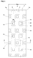
- FIG. 1 illustrates a tread portion 2 of a motorcycle tire for running on rough terrain (hereinafter, simply referred to as "tire") 1 in accordance with an embodiment of the present invention.
- the tire 1 according to the embodiment, for instance, is illustrated as a tire for motocross race.
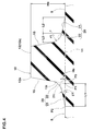
- FIG. 2 illustrates a cross-sectional view taken along lines A-A of the tread portion of FIG. 1 .
- FIG. 2 is a cross-sectional view of the tire 1 under a standard state.
- the standard state is such that the tire is mounted on a standard wheel rim (not shown) with a standard pressure, but is loaded with no tire load.
- dimensions of respective portions of the tire are values specified in the standard state.
- the standard wheel rim is a wheel rim officially approved or recommended for the tire by standards organizations, wherein the standard wheel rim is the "standard rim” specified in JATMA, the "Measuring Rim” in ETRTO, and the “Design Rim” in TRA or the like, for example.
- the standard pressure is a standard pressure officially approved or recommended for the tire by standards organizations, wherein the standard pressure is the "maximum air pressure" in JATMA, the “Inflation Pressure” in ETRTO, and the maximum pressure given in the "Tire Load Limits at Various Cold Inflation Pressures” table in TRA or the like, for example.
- the tread portion 2 includes an outer surface that is curved so as to protrude radially outwardly.
- the tread portion 2 is provided with a plurality of blocks 10.
- Each of the blocks 10 protrudes from a virtual block bottom 11 which extends along a groove bottom 9 forming a part of the outer surface of the tread portion 2.
- the block height Hb from the virtual block bottom 11 to a ground contact surface 12 of the block 10 for example, is in a range of from 6 to 22 mm.
- the axial width Wb of the ground contact surface 12 of the block 10, for example, is in a range of from 5% to 15% of a tread development width TWe. Note that the block height Hb and the width Wb of the block 10 are not limited to these ranges.
- the tread development width TWe is a length in a width direction of the tire portion between tread edges Te and Te measured along the outer surface of the tread portion 2.
- Each tread edge Te means an axially outer edge 10e of the block 10 arranged axially outermost of the tread portion 2.
- the ground contact surface 12 of the block 10 has a substantially square shape.
- any shapes may be employed for the shape of the ground contact surface 12 of the block 10.
- a polygonal shape, a circular shape, an oval shape and the like may be used as the ground contact surface 12 of the block 10.
- FIG. 3 illustrates an enlarged perspective view of the block 10.
- FIG. 3 is an enlarged perspective view of a region 13 surrounded by two-dot chain line shown in FIG. 1 .
- the block 10 includes a block-sidewall main portion 15 and a skirt portion 20.
- a boundary between the block-sidewall main portion 15 and the skirt portion 20 is indicated using two-dot chain line in FIG. 3 .
- FIG. 4 illustrates a cross-sectional view taken along lines B-B of the block 10 illustrated in FIG. 3 .
- This B-B cross section is a section that passes the center 12g (shown in FIG. 3 ) of gravity of the ground contact surface 12 of the block 10, and is perpendicular to the virtual block bottom 11 and an edge 12e of the ground contact surface 12.
- the following description relates to the B-B cross section, the same applies with respect to the section that is perpendicular to the B-B cross section shown in FIG. 3 .
- the block-sidewall main portion 15 extends axially inwardly in a straight shape from the edge 12e of the ground contact surface 12.
- the skirt portion 20 connects between the block-sidewall main portion 15 and the groove bottom 9.
- the skirt portion 20 includes a planar portion 21 and a curved portion 22.
- a boundary between the planar portion 21 and the curved portion 22 is indicated using two-dot chain line.
- the planar portion 21 extends in a straight manner on the side of the groove bottom 9.
- the curved portion 22 is formed as an arc shape (like a fillet) so as to chamfer the corner between the planar portion 21 and the block-sidewall main portion 15.
- Such a block 10 having the skirt portion 20 may effectively suppress crack locally generated on the base portion of the block 10 by bending the curved portion 22 and the planar portion 21 as a whole, when traveling on rough terrain. Accordingly, damage of the block 10 may be effectively prevented to improve durability of the block 10.
- FIGs. 5 illustrate cross-sectional views of the block 10 in accordance with the present embodiment formed through a vulcanization process.
- FIG. 5A is the cross-sectional view when a tread rubber Tg of a green tire is flowing into a recess H of a vulcanization mold M. The recess H is decompressed by discharging the air through a vent hole Bh of the vulcanization mold M.
- FIG. 5B is a cross-sectional view of the block 10 removed from the mold after the vulcanization process. Note that a carcass ply and a tread reinforcing layer, which are disposed in the tread rubber Tg of the green tire, are not illustrated in FIGs. 5A and 5B .
- the recess H has a revere shape of the block 10.
- the width A of the opening for forming the virtual block bottom 11 is greater than the conventional opening width A.
- the block 10 in accordance with the invention may effectively prevent that the thickness t1 of the tread rubber Tg at around the base portion of the block 10 tends to be thin locally, as shown in FIG 5B . Accordingly, the thickness of the tread rubber Tg tends to be uniform, thereby improving durability of the block 10.
- the skirt portion 20 preferably has a skirt length L1 in a range of not less than 0.19 times, more preferably not less than 0.38 times, still further preferably not less than 0.50 times, but preferably not more than 1.00 times, more preferably not more than 0.75 times, still further preferably not more than 0.63 times the block height Hb.
- Such a skirt portion 20 may offer a smooth flow of the rubber G into the recess H to have an uniform thickness of the tread rubber Tg while ensuring a sufficient biting amount of the block 10 into a muddy road.
- the skirt length L1 is a length measured along the virtual groove bottom 11 from an intersection P1 between the virtual block bottom 11 and a virtual extension 15i of the block-sidewall main portion 15 to an intersection P2 between the groove bottom 9 and the skirt portion 20.
- the skirt height Hs of the skirt portion 20 is preferably in a range of not less than 0.02 times, more preferably not less than 0.05 times, but preferably not more than 0.13 times, but preferably not more than 0.08 times the block height Hb.
- the skirt height Hs is a height from the virtual block bottom 11 to an intersection P3 between a virtual extension 21i of the planar portion 21 and the virtual extension 15i of the block-sidewall main portion 15.
- the angle ⁇ 1 of the planar portion 21 with respect to the virtual block bottom 11 is preferably in a range of not less than 5 degrees, more preferably not less than 8 degrees, but preferably not more than 15 degrees, more preferably not more than 12 degrees. Such a planar portion 21 may improve durability of the block 10 while ensuring a sufficient biting amount of the block 10 into a muddy road.
- the length L2 of the planar portion 21 along the virtual block bottom 11 is greater than the length L3 of the curved portion 22 along the virtual block bottom 11.
- Such a planar portion 21 may offer a smooth flow of rubber G during vulcanization process.
- the ratio L3/L2 of the length L3 of the curved portion 22 to the length L2 of the planar portion 21 is preferably in a range of not less than 0.25, more preferably not less than 0.30, but preferably not more than 0.45, more preferably not more than 0.40. If the ratio L3/L2 is less than 0.25, flow resistance of rubber G into the recess during vulcanization tends to increase. On the other hand, if the ratio L3/L2 is more than 0.45, grip performance tends to deteriorate due to lowering of biting amount of the block 10 into muddy road.
- the radius of curvature r1 of the curved portion 22 is preferably in a range of not less than 0.25 times, more preferably not less than 0.30 times, but preferably not more than 0.45 times, but preferably not more than 0.40 times the block height Hb.
- Such a curved portion 22 may reduce flow resistance of rubber G into the recess while ensuring a sufficient biting amount of the block into muddy road.
- the land ratio Lr is preferably in a range of not less than 5%, more preferably not less than 15%, but preferably not more than 35%, more preferably not more than 25%.
- the land ratio Lr is less than 5%, bending moment as well as shearing force acting on one block 10 tends to be high, and there is a possibility to be generated a crack on the base portion of the block 10.
- the land ratio is more than 35%, grip performance tends to deteriorate due to lowering of biting amount of the block 10 into muddy road.
- the land ratio Lr is a ratio Sb/St of a total area Sb of the ground-contact surfaces 12 of the blocks 10 to the total area St of the outer surface of the tread portion when the all grooves are perfectly filled up virtually.
- FIG. 6 is a cross-sectional view of the block 10 in accordance with another embodiment.
- the block 10 illustrated in FIG. 6 includes the planar portion 21 extending at an angle of less than 5 degrees with respect to the virtual block bottom 11, and a step portion 25 connecting between the planar portion 21 and the groove bottom 9.
- Such a block 10 may offer a sufficient rubber volume at the skirt portion 20 due to the planar portion 21. Thus, crack locally generated on the base portion of the block 10 may effectively be prevented.
- FIG. 7 illustrates a cross-sectional view of the block 10 taken along lines C-C of FIG. 6 .
- the thickness H2 of the planar portion 21 according to the embodiment is preferably in a range of from not less than 0.05 times, more preferably not less than 0.08 times, but preferably in a range of not more than 0.15 times, more preferably not more than 0.12 times the block height Hb.
- the planar portion 21 may effectively improve durability of the block 10 by offering an uniform thickness of the groove bottom.
- the step portion 25 is formed as an arc shape to connect between the groove bottom 9 to the planar portion 21 in a chamfered manner.
- the step portion 25 can effectively suppress the damage at the outer edge 21e of the planar portion 21.
- Tires having a basic tread pattern illustrated in FIG. 1 and a block shape illustrated in FIG. 3 or FIG. 6 were manufactured based on details shown in Table 1.
- a tire having the basic tread pattern illustrated in FIG. 1 and a block without having the skirt portion was manufactured. These tires were mounted on the following rim with the inner pressure, and then were tested with respect to block durability and thickness uniformity of the tread rubber.
- the common specifications of tires and test procedures are as follows.
- Each test tire was made to run on a drum having an outer diameter of 1.7 m with a vertical load of 1.95 kN at a speed of 50 km/h. Then, the traveling distance was measured until a block chipping happens. The results are indicated using an index based on Ref. 1 being 100. The larger the value, the better the block durability maintain.
- Block height Hb(mm) 16.0 16.0 16.0 16.0 16.0 16.0 16.0 16.0 16.0 16.0 16.0 16.0 16.0 Skirt length L1 / Block height Hb - 0.63 0.63 0.63 0.19 0.25 0.38 0.50 0.75 Skirt height Hs / Block height Hb - 0.06 0.03 0.13 0.19 0.06 0.06 0.06 0.06 0.06 0.06 0.06 Curved portion length L3 / Planar portion length L2 - 0.36 0.36 0.36 0.36 0.36 0.36 0.36 0.36 0.36 0.36 0.36 0.36 0.36 0.36 0.36 0.36 Planar portion angle ⁇ 1 - 10.0 10.0 10.0 10.0 10.0 10.0 10.0 10.0 10.0 Curved portion radius / Block height Hb - 0.35 0.35 0.35 0.35 0.35 0.35 0.35 0.35 0.35 0.35 0.35 0.35 0.35 0.35 0.35 0.35 0.35 0.35 0.35 0.35 0.35 0.35 0.35 0.35 0.35 0.35 0.35 0.35 0.35 0.35 0.35 0.35 0.35
- FIG. 3 FIG. 3 FIG. 3 FIG. 3 FIG. 3 FIG. 3 FIG. 3 FIG. 6 Block height Hb(mm) 16.0 16.0 16.0 16.0 16.0 16.0 16.0 16.0 16.0 16.0 16.0 Skirt length L1 / Block height Hb 100 0.63 0.63 0.63 0.63 0.63 0.63 0.63 0.63 Skirt height Hs / Block height Hb 0.06 0.06 0.06 0.06 0.06 0.06 0.06 0.06 0.06 0.06 0.06 0.06 0.06 0.06 0.06 0.06 0.06 0.06 0.06 0.06 0.06 0.06 0.06 0.06 0.06 0.06 0.06 0.06 0.06 0.06 0.06 0.06 0.06 0.06 0.06 0.06 0.06 0.06 0.06 0.06 0.06 0.06 0.06 0.06 0.06 0.06 0.06 0.06 0.06 0.06 0.06 0.06 0.06 0.06 0.06 0.06 0.06 0.06 0.06 0.06 0.06 0.06 0.06 0.06 0.06 0.06 0.06 0.06 0.06 Curved portion length L3 / Planar portion length L2 0.36 0.25 0.3
Landscapes
- Engineering & Computer Science (AREA)
- Mechanical Engineering (AREA)
- Tires In General (AREA)
Description
- The present invention relates to a motorcycle tire for running on rough terrain capable of improving durability of blocks.
- For instance, motorcycle tires for running on rough terrain for using motocross or the like include a tread portion provided with a plurality of blocks. When these tires travel on off-road such as sandy, soil or muddy road, the blocks can bite the road to maintain grip performance.
- In general, the blocks are molded using a recess of a mold through a vulcanization process. In the vulcanization process, tread rubber around blocks flows significantly. Such a significant rubber flow may cause a problem that a tread rubber thickness tends to be thin locally around the blocks and deteriorates durability of the blocks.
- Furthermore, when traveling, a large stress and bending moment acts on the base portion of the respective blocks. Thus, there was a problem that damage tends to concentrate the base portion of the blocks.
- In order to improve durability of tread blocks, the following
patent document 1, for instance, has proposed a motorcycle tire for running on rough terrain having an improved shape of a base portion of a block. - Patent document 1: Japanese Unexamined Patent Application Publication No.
2004-351956 - Unfortunately, there has been room for further improvement of durability of blocks even on the motorcycle for running on rough terrain tire in accordance with the above mentioned
patent document 1. - The present invention has been made in view of circumstances described above, and has a main object to provide a motorcycle tire for running on rough terrain capable of improving durability of blocks.
- The present invention provide a motorcycle tire for running on rough terrain including a tread portion provided with a plurality of blocks protruding from a virtual block bottom which extends along a groove bottom, in a block cross section passing a center of gravity of a ground contact surface of the blocks and being perpendicular to the virtual block bottom, the blocks including a block-sidewall main portion extending radially inwardly in a straight shape from an edge of the ground contact surface and a skirt portion that connects the block-sidewall main portion to the groove bottom, and the skirt portion including a planar portion extending in a straight shape on the side of the groove bottom and a curved portion so as to connect the block-sidewall main portion to the planar portion in a chamfered manner.
- In the motorcycle tire for running on rough terrain according to the present invention, a skirt length (L1) measured along the virtual groove bottom from an intersection (P1) between the virtual block bottom and a virtual extension of the block-sidewall main portion to an intersection (P2) between the groove bottom and the skirt portion is preferably in a range of from 0.19 to 1.00 times a block height (Hb) from the virtual block bottom to the ground contact surface.
- In the motorcycle tire for running on rough terrain according to the present invention, a skirt height (Hs) from the virtual block bottom to an intersection (P3) between a virtual extension of the planar portion and a virtual extension of the block-sidewall main portion is preferably in a range of from 0.02 to 0.13 times a block height (Hb) from the virtual block bottom to the ground contact surface.
- In the motorcycle tire for running on rough terrain according to the present invention, a length of the planar portion along the virtual block bottom is preferably greater than a length of the curved portion along the virtual block bottom.
- In the motorcycle tire for running on rough terrain according to the present invention, the planar portion is preferably inclined at an angle of from 5 to 15 degrees with respect to the virtual block bottom.
- In the motorcycle tire for running on rough terrain according to the present invention, the planar portion preferably has an angle of less than 5 degrees with respect to the virtual block bottom.
- The motorcycle tire for running on rough terrain in accordance with the present invention includes the tread portion provided with a plurality of blocks protruding from the virtual block bottom which extends along the groove bottom. In a block cross section passing the center of gravity of the ground contact surface of the blocks and being perpendicular to the virtual block bottom, the blocks include the block-sidewall main portion extending radially inwardly in a straight shape from the edge of the ground contact surface and the skirt portion that connects the block-sidewall main portion to the groove bottom. Furthermore, the skirt portion includes the planar portion extending in a straight shape on the side of the groove bottom and the curved portion so as to connect the block-sidewall main portion to the planar portion in a chamfered manner.
- The blocks having the skirt portion may effectively suppress crack locally generated on the base portion of the blocks by bending the curved portion and the planar portion when traveling on rough terrain.
- Since the blocks in accordance with the present invention include the skirt portion, the virtual block bottom is greater than the conventional one. Accordingly, a recess of a vulcanization mold for molding each block has an opening greater than the conventional one. Thus, when each block is molded through the vulcanization process, rubber gathered from a wide area flows into the recess. Therefore, the blocks in accordance with the present invention may suppress a significant local rubber flow, and then may prevent the problem that a tread rubber thickness around the blocks tends to be thin locally.
- As described above, the motorcycle tire for running on rough terrain in accordance with the present invention may improve durability of blocks.
-
-
FIG. 1 is a development view of a tread portion of a pneumatic tire in accordance with an embodiment of the invention. -
FIG. 2 is a cross-sectional view taken along lines A-A ofFIG. 1 . -
FIG. 3 is an enlarged perspective view of a block illustrated inFIG. 1 . -
FIG. 4 is a cross-sectional view taken along lines B-B of the block illustrated inFIG. 3 . -
FIG. 5A is a cross-sectional view of the block during vulcanization process. -
FIG. 5B is a cross-sectional view of the block after vulcanization process. -
FIG. 6 is a cross-sectional view of the block in accordance with another embodiment. -
FIG. 7 is a cross-sectional view taken along lines C-C ofFIG. 6 . - An embodiment of the present invention will be explained below with reference to the accompanying drawings.
FIG. 1 illustrates atread portion 2 of a motorcycle tire for running on rough terrain (hereinafter, simply referred to as "tire") 1 in accordance with an embodiment of the present invention. Thetire 1 according to the embodiment, for instance, is illustrated as a tire for motocross race. -
FIG. 2 illustrates a cross-sectional view taken along lines A-A of the tread portion ofFIG. 1 .FIG. 2 is a cross-sectional view of thetire 1 under a standard state. The standard state is such that the tire is mounted on a standard wheel rim (not shown) with a standard pressure, but is loaded with no tire load. In this description, unless otherwise noted, dimensions of respective portions of the tire are values specified in the standard state. - The standard wheel rim is a wheel rim officially approved or recommended for the tire by standards organizations, wherein the standard wheel rim is the "standard rim" specified in JATMA, the "Measuring Rim" in ETRTO, and the "Design Rim" in TRA or the like, for example.
- The standard pressure is a standard pressure officially approved or recommended for the tire by standards organizations, wherein the standard pressure is the "maximum air pressure" in JATMA, the "Inflation Pressure" in ETRTO, and the maximum pressure given in the "Tire Load Limits at Various Cold Inflation Pressures" table in TRA or the like, for example.
- As illustrated in
FIG. 2 , thetread portion 2 includes an outer surface that is curved so as to protrude radially outwardly. - The
tread portion 2 is provided with a plurality ofblocks 10. Each of theblocks 10 protrudes from avirtual block bottom 11 which extends along agroove bottom 9 forming a part of the outer surface of thetread portion 2. For traveling on rough terrain, the block height Hb from thevirtual block bottom 11 to aground contact surface 12 of theblock 10, for example, is in a range of from 6 to 22 mm. The axial width Wb of theground contact surface 12 of theblock 10, for example, is in a range of from 5% to 15% of a tread development width TWe. Note that the block height Hb and the width Wb of theblock 10 are not limited to these ranges. - The tread development width TWe is a length in a width direction of the tire portion between tread edges Te and Te measured along the outer surface of the
tread portion 2. Each tread edge Te means an axiallyouter edge 10e of theblock 10 arranged axially outermost of thetread portion 2. - As illustrated in
FIG. 1 , theground contact surface 12 of theblock 10 has a substantially square shape. Alternatively, any shapes may be employed for the shape of theground contact surface 12 of theblock 10. For instance, a polygonal shape, a circular shape, an oval shape and the like may be used as theground contact surface 12 of theblock 10. -
FIG. 3 illustrates an enlarged perspective view of theblock 10.FIG. 3 is an enlarged perspective view of aregion 13 surrounded by two-dot chain line shown inFIG. 1 . As illustrated inFIG. 3 , theblock 10 includes a block-sidewallmain portion 15 and askirt portion 20. In order to help understanding, a boundary between the block-sidewallmain portion 15 and theskirt portion 20 is indicated using two-dot chain line inFIG. 3 . -
FIG. 4 illustrates a cross-sectional view taken along lines B-B of theblock 10 illustrated inFIG. 3 . This B-B cross section is a section that passes thecenter 12g (shown inFIG. 3 ) of gravity of theground contact surface 12 of theblock 10, and is perpendicular to the virtual block bottom 11 and anedge 12e of theground contact surface 12. Although the following description relates to the B-B cross section, the same applies with respect to the section that is perpendicular to the B-B cross section shown inFIG. 3 . - As illustrated in
FIG. 4 , the block-sidewallmain portion 15 extends axially inwardly in a straight shape from theedge 12e of theground contact surface 12. Theskirt portion 20 connects between the block-sidewallmain portion 15 and thegroove bottom 9. - The
skirt portion 20 includes aplanar portion 21 and acurved portion 22. InFIG. 3 , to help understanding, a boundary between theplanar portion 21 and thecurved portion 22 is indicated using two-dot chain line. As illustrated inFIG. 4 , theplanar portion 21 extends in a straight manner on the side of thegroove bottom 9. Thecurved portion 22 is formed as an arc shape (like a fillet) so as to chamfer the corner between theplanar portion 21 and the block-sidewallmain portion 15. - Such a
block 10 having theskirt portion 20 may effectively suppress crack locally generated on the base portion of theblock 10 by bending thecurved portion 22 and theplanar portion 21 as a whole, when traveling on rough terrain. Accordingly, damage of theblock 10 may be effectively prevented to improve durability of theblock 10. -
FIGs. 5 illustrate cross-sectional views of theblock 10 in accordance with the present embodiment formed through a vulcanization process.FIG. 5A is the cross-sectional view when a tread rubber Tg of a green tire is flowing into a recess H of a vulcanization mold M. The recess H is decompressed by discharging the air through a vent hole Bh of the vulcanization mold M.FIG. 5B is a cross-sectional view of theblock 10 removed from the mold after the vulcanization process. Note that a carcass ply and a tread reinforcing layer, which are disposed in the tread rubber Tg of the green tire, are not illustrated inFIGs. 5A and 5B . - As illustrated in
FIG. 5A , the recess H has a revere shape of theblock 10. Thus, the width A of the opening for forming the virtual block bottom 11 is greater than the conventional opening width A. When theblock 10 is molded during the vulcanization process, rubber G gathered from a wide area flows into the recess H. Furthermore, the rubber G may flows into the recess H smoothly along an outer surface of the recess H. - Therefore, a significant local rubber flow may be prevented, and then the
block 10 in accordance with the invention may effectively prevent that the thickness t1 of the tread rubber Tg at around the base portion of theblock 10 tends to be thin locally, as shown inFIG 5B . Accordingly, the thickness of the tread rubber Tg tends to be uniform, thereby improving durability of theblock 10. - In order to further improve the effects, as shown in
FIG. 4 , theskirt portion 20 preferably has a skirt length L1 in a range of not less than 0.19 times, more preferably not less than 0.38 times, still further preferably not less than 0.50 times, but preferably not more than 1.00 times, more preferably not more than 0.75 times, still further preferably not more than 0.63 times the block height Hb. Such askirt portion 20 may offer a smooth flow of the rubber G into the recess H to have an uniform thickness of the tread rubber Tg while ensuring a sufficient biting amount of theblock 10 into a muddy road. The skirt length L1 is a length measured along the virtual groove bottom 11 from an intersection P1 between the virtual block bottom 11 and avirtual extension 15i of the block-sidewallmain portion 15 to an intersection P2 between thegroove bottom 9 and theskirt portion 20. - In the same point of view, the skirt height Hs of the
skirt portion 20 is preferably in a range of not less than 0.02 times, more preferably not less than 0.05 times, but preferably not more than 0.13 times, but preferably not more than 0.08 times the block height Hb. The skirt height Hs is a height from the virtual block bottom 11 to an intersection P3 between avirtual extension 21i of theplanar portion 21 and thevirtual extension 15i of the block-sidewallmain portion 15. - The angle θ1 of the
planar portion 21 with respect to the virtual block bottom 11 is preferably in a range of not less than 5 degrees, more preferably not less than 8 degrees, but preferably not more than 15 degrees, more preferably not more than 12 degrees. Such aplanar portion 21 may improve durability of theblock 10 while ensuring a sufficient biting amount of theblock 10 into a muddy road. - Preferably, the length L2 of the
planar portion 21 along the virtual block bottom 11 is greater than the length L3 of thecurved portion 22 along the virtual block bottom 11. Such aplanar portion 21 may offer a smooth flow of rubber G during vulcanization process. - The ratio L3/L2 of the length L3 of the
curved portion 22 to the length L2 of theplanar portion 21 is preferably in a range of not less than 0.25, more preferably not less than 0.30, but preferably not more than 0.45, more preferably not more than 0.40. If the ratio L3/L2 is less than 0.25, flow resistance of rubber G into the recess during vulcanization tends to increase. On the other hand, if the ratio L3/L2 is more than 0.45, grip performance tends to deteriorate due to lowering of biting amount of theblock 10 into muddy road. - The radius of curvature r1 of the
curved portion 22 is preferably in a range of not less than 0.25 times, more preferably not less than 0.30 times, but preferably not more than 0.45 times, but preferably not more than 0.40 times the block height Hb. Such acurved portion 22 may reduce flow resistance of rubber G into the recess while ensuring a sufficient biting amount of the block into muddy road. - As for a motocross tire, the land ratio Lr is preferably in a range of not less than 5%, more preferably not less than 15%, but preferably not more than 35%, more preferably not more than 25%. When the land ratio Lr is less than 5%, bending moment as well as shearing force acting on one
block 10 tends to be high, and there is a possibility to be generated a crack on the base portion of theblock 10. On the other hand, when the land ratio is more than 35%, grip performance tends to deteriorate due to lowering of biting amount of theblock 10 into muddy road. As used herein, the land ratio Lr is a ratio Sb/St of a total area Sb of the ground-contact surfaces 12 of theblocks 10 to the total area St of the outer surface of the tread portion when the all grooves are perfectly filled up virtually. -
FIG. 6 is a cross-sectional view of theblock 10 in accordance with another embodiment. Theblock 10 illustrated inFIG. 6 includes theplanar portion 21 extending at an angle of less than 5 degrees with respect to the virtual block bottom 11, and astep portion 25 connecting between theplanar portion 21 and thegroove bottom 9. Such ablock 10 may offer a sufficient rubber volume at theskirt portion 20 due to theplanar portion 21. Thus, crack locally generated on the base portion of theblock 10 may effectively be prevented. -
FIG. 7 illustrates a cross-sectional view of theblock 10 taken along lines C-C ofFIG. 6 . As illustrates inFIG. 7 , the thickness H2 of theplanar portion 21 according to the embodiment is preferably in a range of from not less than 0.05 times, more preferably not less than 0.08 times, but preferably in a range of not more than 0.15 times, more preferably not more than 0.12 times the block height Hb. Theplanar portion 21 may effectively improve durability of theblock 10 by offering an uniform thickness of the groove bottom. - The
step portion 25 is formed as an arc shape to connect between thegroove bottom 9 to theplanar portion 21 in a chamfered manner. Thestep portion 25 can effectively suppress the damage at theouter edge 21e of theplanar portion 21. - While the embodiments in accordance with the present invention have been described in detail, the present invention is not limited to the illustrated embodiments, but can be modified and carried out in various aspects.
- Tires having a basic tread pattern illustrated in
FIG. 1 and a block shape illustrated inFIG. 3 orFIG. 6 were manufactured based on details shown in Table 1. For the comparative example, a tire having the basic tread pattern illustrated inFIG. 1 and a block without having the skirt portion was manufactured. These tires were mounted on the following rim with the inner pressure, and then were tested with respect to block durability and thickness uniformity of the tread rubber. The common specifications of tires and test procedures are as follows. - Tire size: 120/80-19
- Rim size: 2.15x19
- Internal pressure: 80 kPa
- Each test tire was made to run on a drum having an outer diameter of 1.7 m with a vertical load of 1.95 kN at a speed of 50 km/h. Then, the traveling distance was measured until a block chipping happens. The results are indicated using an index based on Ref. 1 being 100. The larger the value, the better the block durability maintain.
- The difference between a rubber thickness of the groove bottom where no block is provided and a rubber thickness at an outer edge of the skirt portion was measured. The results are indicated using an index based on Ref. 1 being 100. The smaller the value, the better the sufficient rubber volume around the skirt portion is.
- The test results are shown in table 1.
[Table 1] Ref. 1 Ex. 1 Ex. 2 Ex. 3 Ex. 4 Ex. 5 Ex. 6 Ex. 7 Ex. 8 Ex. 9 Block shape - FIG. 3 FIG. 3 FIG. 3 FIG. 3 FIG. 3 FIG. 3 FIG. 3 FIG. 3 FIG. 3 Block height Hb(mm) 16.0 16.0 16.0 16.0 16.0 16.0 16.0 16.0 16.0 16.0 Skirt length L1 / Block height Hb - 0.63 0.63 0.63 0.63 0.19 0.25 0.38 0.50 0.75 Skirt height Hs / Block height Hb - 0.06 0.03 0.13 0.19 0.06 0.06 0.06 0.06 0.06 Curved portion length L3 / Planar portion length L2 - 0.36 0.36 0.36 0.36 0.36 0.36 0.36 0.36 0.36 Planar portion angle θ1 - 10.0 10.0 10.0 10.0 10.0 10.0 10.0 10.0 10.0 Curved portion radius / Block height Hb - 0.35 0.35 0.35 0.35 0.35 0.35 0.35 0.35 0.35 Block durability (Index) 100 110 105 107 104 104 105 105 107 107 Thickness uniformity of tread rubber (Index) 100 70 85 79 95 92 73 70 70 76 Ex. 10 Ex. 11 Ex. 12 Ex. 13 Ex. 14 Ex. 15 Ex. 16 Ex. 17 Ex. 18 Ex. 19 Block shape FIG. 3 FIG. 3 FIG. 3 FIG. 3 FIG. 3 FIG. 3 FIG. 3 FIG. 3 FIG. 3 FIG. 6 Block height Hb(mm) 16.0 16.0 16.0 16.0 16.0 16.0 16.0 16.0 16.0 16.0 Skirt length L1 / Block height Hb 100 0.63 0.63 0.63 0.63 0.63 0.63 0.63 0.63 0.63 Skirt height Hs / Block height Hb 0.06 0.06 0.06 0.06 0.06 0.06 0.06 0.06 0.06 0.06 Curved portion length L3 / Planar portion length L2 0.36 0.25 0.3 0.4 0.45 0.36 0.36 0.36 0.36 0.36 Planar portion angle θ1 10 10 10 10 10 5 15 10 10 10 Curved portion radius / Block height Hb 0.35 0.35 0.35 0.35 0.35 0.35 0.35 0.25 0.45 0.35 Block durability (Index) 104 106 108 108 105 105 107 104 108 112 Thickness uniformity of tread rubber (Index) 85 83 76 73 84 75 87 80 77 73 - From the test results, it was confirmed that the example tires has improved durability of blocks.
-
- 2
- Tread portion
- 9
- Groove bottom
- 10
- Block
- 11
- Virtual block bottom
- 12
- Ground contact surface
- 15
- Block-sidewall main portion
- 20
- Skirt portion
- 21
- Planar portion
- 22
- Curved portion
Claims (6)
- A motorcycle tire for running on rough terrain comprising:a tread portion provided with a plurality of blocks protruding from a virtual block bottom which extends along a groove bottom;in a block cross section passing a center of gravity of a ground contact surface of the blocks and being perpendicular to the virtual block bottom, the blocks comprising a block-sidewall main portion extending radially inwardly in a straight shape from an edge of the ground contact surface and a skirt portion that connects the block-sidewall main portion to the groove bottom; andthe skirt portion comprising a planar portion extending in a straight shape on the side of the groove bottom and a curved portion so as to connect the block-sidewall main portion to the planar portion in a chamfered manner.
- The pneumatic tire according to claim 1, wherein a skirt length (L1) measured along the virtual groove bottom from an intersection (P1) between the virtual block bottom and a virtual extension of the block-sidewall main portion to an intersection (P2) between the groove bottom and the skirt portion is in a range of from 0.19 to 1.00 times a block height (Hb) from the virtual block bottom to the ground contact surface.
- The motorcycle tire for running on rough terrain according to claim 1 or 2, wherein a skirt height (Hs) from the virtual block bottom to an intersection (P3) between a virtual extension of the planar portion and a virtual extension of the block-sidewall main portion is in a range of from 0.02 to 0.13 times a block height (Hb) from the virtual block bottom to the ground contact surface.
- The motorcycle tire for running on rough terrain according to any one of claims 1 to 3, wherein a length of the planar portion along the virtual block bottom is greater than a length of the curved portion along the virtual block bottom.
- The motorcycle tire for running on rough terrain according to any one of claims 1 to 4, wherein the planar portion is inclined at an angle of from 5 to 15 degrees with respect to the virtual block bottom.
- The motorcycle tire for running on rough terrain according to any one of claims 1 to 4, wherein the planar portion has an angle of less than 5 degrees with respect to the virtual block bottom.
Applications Claiming Priority (2)
| Application Number | Priority Date | Filing Date | Title |
|---|---|---|---|
| JP2013215681A JP5957429B2 (en) | 2013-10-16 | 2013-10-16 | Motorcycle tires for running on rough terrain |
| PCT/JP2014/076394 WO2015056574A1 (en) | 2013-10-16 | 2014-10-02 | Motorcycle tire for traveling on rough terrain |
Publications (3)
| Publication Number | Publication Date |
|---|---|
| EP3047981A1 true EP3047981A1 (en) | 2016-07-27 |
| EP3047981A4 EP3047981A4 (en) | 2017-05-10 |
| EP3047981B1 EP3047981B1 (en) | 2020-02-12 |
Family
ID=52828022
Family Applications (1)
| Application Number | Title | Priority Date | Filing Date |
|---|---|---|---|
| EP14853854.9A Active EP3047981B1 (en) | 2013-10-16 | 2014-10-02 | Motorcycle tire for traveling on rough terrain |
Country Status (5)
| Country | Link |
|---|---|
| US (1) | US10059152B2 (en) |
| EP (1) | EP3047981B1 (en) |
| JP (1) | JP5957429B2 (en) |
| CN (1) | CN105579252B (en) |
| WO (1) | WO2015056574A1 (en) |
Cited By (2)
| Publication number | Priority date | Publication date | Assignee | Title |
|---|---|---|---|---|
| WO2017187295A1 (en) * | 2016-04-27 | 2017-11-02 | Pirelli Tyre S.P.A. | Tyre for motorcycle wheels |
| EP3505370A1 (en) * | 2017-12-19 | 2019-07-03 | Sumitomo Rubber Industries Ltd. | Tyre and tyre set |
Families Citing this family (8)
| Publication number | Priority date | Publication date | Assignee | Title |
|---|---|---|---|---|
| WO2018060796A1 (en) * | 2016-09-28 | 2018-04-05 | Pirelli Tyre S.P.A. | Motorcycles tyre |
| JP6862898B2 (en) * | 2017-02-20 | 2021-04-21 | 住友ゴム工業株式会社 | tire |
| US11498368B2 (en) * | 2017-10-27 | 2022-11-15 | Shinji Marui | Tire with enhanced tread |
| CN109130708B (en) * | 2018-08-13 | 2024-08-06 | 厦门正新橡胶工业有限公司 | Tread pattern structure of pneumatic tire for dangerous pulling force vehicle |
| JP7491009B2 (en) * | 2020-03-24 | 2024-05-28 | 住友ゴム工業株式会社 | Motorcycle tires for rough terrain |
| JP7491010B2 (en) * | 2020-03-24 | 2024-05-28 | 住友ゴム工業株式会社 | Motorcycle tires for rough terrain |
| CN112109500B (en) * | 2020-10-31 | 2025-06-24 | 风神轮胎股份有限公司 | Block-shaped tread block of a tire |
| CN114312158A (en) * | 2021-12-02 | 2022-04-12 | 山东玲珑轮胎股份有限公司 | Low-noise tire pattern and low-noise all-terrain tire |
Family Cites Families (10)
| Publication number | Priority date | Publication date | Assignee | Title |
|---|---|---|---|---|
| JPS5845103A (en) | 1981-09-12 | 1983-03-16 | Hitachi Chem Co Ltd | Carbon sphere and graphite sphere |
| JPS5845103U (en) * | 1981-09-21 | 1983-03-26 | 住友ゴム工業株式会社 | motorcycle tires |
| JP4233387B2 (en) | 2003-05-27 | 2009-03-04 | 株式会社ブリヂストン | PNEUMATIC TIRE AND METHOD OF INSTALLING PNEUMATIC TIRE |
| JP3808077B2 (en) * | 2004-01-16 | 2006-08-09 | 株式会社マルイ | Bicycle tire |
| JP3943095B2 (en) * | 2004-03-31 | 2007-07-11 | 住友ゴム工業株式会社 | Motorcycle tires |
| JP4690852B2 (en) * | 2005-10-24 | 2011-06-01 | 住友ゴム工業株式会社 | Pneumatic tire |
| JP4814980B2 (en) * | 2009-06-17 | 2011-11-16 | 住友ゴム工業株式会社 | Pneumatic tire for running on rough terrain |
| JP5161933B2 (en) * | 2010-07-28 | 2013-03-13 | 住友ゴム工業株式会社 | Motorcycle tires for running on rough terrain |
| JP5320491B2 (en) * | 2011-07-13 | 2013-10-23 | 住友ゴム工業株式会社 | Motorcycle tires for running on rough terrain |
| JP5647642B2 (en) * | 2012-04-09 | 2015-01-07 | 住友ゴム工業株式会社 | Pneumatic tire for running on rough terrain |
-
2013
- 2013-10-16 JP JP2013215681A patent/JP5957429B2/en active Active
-
2014
- 2014-10-02 CN CN201480051908.3A patent/CN105579252B/en not_active Expired - Fee Related
- 2014-10-02 EP EP14853854.9A patent/EP3047981B1/en active Active
- 2014-10-02 US US15/025,141 patent/US10059152B2/en active Active
- 2014-10-02 WO PCT/JP2014/076394 patent/WO2015056574A1/en not_active Ceased
Cited By (3)
| Publication number | Priority date | Publication date | Assignee | Title |
|---|---|---|---|---|
| WO2017187295A1 (en) * | 2016-04-27 | 2017-11-02 | Pirelli Tyre S.P.A. | Tyre for motorcycle wheels |
| EP3744540A1 (en) | 2016-04-27 | 2020-12-02 | Pirelli Tyre S.p.A. | Tyre for motorcycle wheels |
| EP3505370A1 (en) * | 2017-12-19 | 2019-07-03 | Sumitomo Rubber Industries Ltd. | Tyre and tyre set |
Also Published As
| Publication number | Publication date |
|---|---|
| US10059152B2 (en) | 2018-08-28 |
| US20160236516A1 (en) | 2016-08-18 |
| JP5957429B2 (en) | 2016-07-27 |
| EP3047981A4 (en) | 2017-05-10 |
| JP2015077880A (en) | 2015-04-23 |
| EP3047981B1 (en) | 2020-02-12 |
| CN105579252B (en) | 2017-11-24 |
| WO2015056574A1 (en) | 2015-04-23 |
| CN105579252A (en) | 2016-05-11 |
Similar Documents
| Publication | Publication Date | Title |
|---|---|---|
| EP3047981B1 (en) | Motorcycle tire for traveling on rough terrain | |
| EP2639084B1 (en) | Pneumatic tire | |
| EP3056357B1 (en) | Motorcycle tire for uneven ground travel | |
| AU2013236260B2 (en) | Pneumatic tire | |
| CN105358339B (en) | Pneumatic tire | |
| US8887778B2 (en) | Motorcycle tire for off-road traveling | |
| US12227033B2 (en) | Pneumatic tire | |
| EP2760682B1 (en) | Tyre for motorcycles | |
| WO2015118786A1 (en) | Pneumatic tire | |
| CN103963571A (en) | Motorcycle tire for running on rough terrain | |
| JP2013180637A (en) | Pneumatic tire | |
| EP2650145A1 (en) | Pneumatic tire for running on rough terrain | |
| JP7127521B2 (en) | pneumatic tire | |
| EP3616945B1 (en) | Motorcycle tyre for off-road | |
| EP3597451B1 (en) | Tyre | |
| EP2732984A1 (en) | Pneumatic radial tire | |
| JP4318690B2 (en) | Pneumatic tire for running on rough terrain | |
| US20220097465A1 (en) | Pneumatic tire | |
| JP4891614B2 (en) | Pneumatic tire for running on rough terrain | |
| JP4333822B2 (en) | Tires for heavy vehicles | |
| EP3929004B1 (en) | Motorcycle tire | |
| JPH0880712A (en) | Heavy load radial tire for winter season | |
| JP2013035460A (en) | Pneumatic tire |
Legal Events
| Date | Code | Title | Description |
|---|---|---|---|
| PUAI | Public reference made under article 153(3) epc to a published international application that has entered the european phase |
Free format text: ORIGINAL CODE: 0009012 |
|
| 17P | Request for examination filed |
Effective date: 20160419 |
|
| AK | Designated contracting states |
Kind code of ref document: A1 Designated state(s): AL AT BE BG CH CY CZ DE DK EE ES FI FR GB GR HR HU IE IS IT LI LT LU LV MC MK MT NL NO PL PT RO RS SE SI SK SM TR |
|
| AX | Request for extension of the european patent |
Extension state: BA ME |
|
| DAX | Request for extension of the european patent (deleted) | ||
| A4 | Supplementary search report drawn up and despatched |
Effective date: 20170407 |
|
| RIC1 | Information provided on ipc code assigned before grant |
Ipc: B60C 11/13 20060101ALI20170403BHEP Ipc: B60C 11/03 20060101ALI20170403BHEP Ipc: B60C 11/11 20060101AFI20170403BHEP |
|
| GRAP | Despatch of communication of intention to grant a patent |
Free format text: ORIGINAL CODE: EPIDOSNIGR1 |
|
| STAA | Information on the status of an ep patent application or granted ep patent |
Free format text: STATUS: GRANT OF PATENT IS INTENDED |
|
| INTG | Intention to grant announced |
Effective date: 20191018 |
|
| RIN1 | Information on inventor provided before grant (corrected) |
Inventor name: SUEISHI MAKOTO |
|
| GRAS | Grant fee paid |
Free format text: ORIGINAL CODE: EPIDOSNIGR3 |
|
| GRAA | (expected) grant |
Free format text: ORIGINAL CODE: 0009210 |
|
| STAA | Information on the status of an ep patent application or granted ep patent |
Free format text: STATUS: THE PATENT HAS BEEN GRANTED |
|
| AK | Designated contracting states |
Kind code of ref document: B1 Designated state(s): AL AT BE BG CH CY CZ DE DK EE ES FI FR GB GR HR HU IE IS IT LI LT LU LV MC MK MT NL NO PL PT RO RS SE SI SK SM TR |
|
| REG | Reference to a national code |
Ref country code: GB Ref legal event code: FG4D |
|
| REG | Reference to a national code |
Ref country code: CH Ref legal event code: EP |
|
| REG | Reference to a national code |
Ref country code: AT Ref legal event code: REF Ref document number: 1231613 Country of ref document: AT Kind code of ref document: T Effective date: 20200215 |
|
| REG | Reference to a national code |
Ref country code: DE Ref legal event code: R096 Ref document number: 602014061038 Country of ref document: DE |
|
| REG | Reference to a national code |
Ref country code: IE Ref legal event code: FG4D |
|
| PG25 | Lapsed in a contracting state [announced via postgrant information from national office to epo] |
Ref country code: FI Free format text: LAPSE BECAUSE OF FAILURE TO SUBMIT A TRANSLATION OF THE DESCRIPTION OR TO PAY THE FEE WITHIN THE PRESCRIBED TIME-LIMIT Effective date: 20200212 Ref country code: RS Free format text: LAPSE BECAUSE OF FAILURE TO SUBMIT A TRANSLATION OF THE DESCRIPTION OR TO PAY THE FEE WITHIN THE PRESCRIBED TIME-LIMIT Effective date: 20200212 Ref country code: NO Free format text: LAPSE BECAUSE OF FAILURE TO SUBMIT A TRANSLATION OF THE DESCRIPTION OR TO PAY THE FEE WITHIN THE PRESCRIBED TIME-LIMIT Effective date: 20200512 |
|
| REG | Reference to a national code |
Ref country code: LT Ref legal event code: MG4D |
|
| REG | Reference to a national code |
Ref country code: NL Ref legal event code: MP Effective date: 20200212 |
|
| PG25 | Lapsed in a contracting state [announced via postgrant information from national office to epo] |
Ref country code: GR Free format text: LAPSE BECAUSE OF FAILURE TO SUBMIT A TRANSLATION OF THE DESCRIPTION OR TO PAY THE FEE WITHIN THE PRESCRIBED TIME-LIMIT Effective date: 20200513 Ref country code: BG Free format text: LAPSE BECAUSE OF FAILURE TO SUBMIT A TRANSLATION OF THE DESCRIPTION OR TO PAY THE FEE WITHIN THE PRESCRIBED TIME-LIMIT Effective date: 20200512 Ref country code: IS Free format text: LAPSE BECAUSE OF FAILURE TO SUBMIT A TRANSLATION OF THE DESCRIPTION OR TO PAY THE FEE WITHIN THE PRESCRIBED TIME-LIMIT Effective date: 20200612 Ref country code: SE Free format text: LAPSE BECAUSE OF FAILURE TO SUBMIT A TRANSLATION OF THE DESCRIPTION OR TO PAY THE FEE WITHIN THE PRESCRIBED TIME-LIMIT Effective date: 20200212 Ref country code: HR Free format text: LAPSE BECAUSE OF FAILURE TO SUBMIT A TRANSLATION OF THE DESCRIPTION OR TO PAY THE FEE WITHIN THE PRESCRIBED TIME-LIMIT Effective date: 20200212 Ref country code: LV Free format text: LAPSE BECAUSE OF FAILURE TO SUBMIT A TRANSLATION OF THE DESCRIPTION OR TO PAY THE FEE WITHIN THE PRESCRIBED TIME-LIMIT Effective date: 20200212 |
|
| PG25 | Lapsed in a contracting state [announced via postgrant information from national office to epo] |
Ref country code: NL Free format text: LAPSE BECAUSE OF FAILURE TO SUBMIT A TRANSLATION OF THE DESCRIPTION OR TO PAY THE FEE WITHIN THE PRESCRIBED TIME-LIMIT Effective date: 20200212 |
|
| PG25 | Lapsed in a contracting state [announced via postgrant information from national office to epo] |
Ref country code: CZ Free format text: LAPSE BECAUSE OF FAILURE TO SUBMIT A TRANSLATION OF THE DESCRIPTION OR TO PAY THE FEE WITHIN THE PRESCRIBED TIME-LIMIT Effective date: 20200212 Ref country code: DK Free format text: LAPSE BECAUSE OF FAILURE TO SUBMIT A TRANSLATION OF THE DESCRIPTION OR TO PAY THE FEE WITHIN THE PRESCRIBED TIME-LIMIT Effective date: 20200212 Ref country code: SM Free format text: LAPSE BECAUSE OF FAILURE TO SUBMIT A TRANSLATION OF THE DESCRIPTION OR TO PAY THE FEE WITHIN THE PRESCRIBED TIME-LIMIT Effective date: 20200212 Ref country code: LT Free format text: LAPSE BECAUSE OF FAILURE TO SUBMIT A TRANSLATION OF THE DESCRIPTION OR TO PAY THE FEE WITHIN THE PRESCRIBED TIME-LIMIT Effective date: 20200212 Ref country code: EE Free format text: LAPSE BECAUSE OF FAILURE TO SUBMIT A TRANSLATION OF THE DESCRIPTION OR TO PAY THE FEE WITHIN THE PRESCRIBED TIME-LIMIT Effective date: 20200212 Ref country code: SK Free format text: LAPSE BECAUSE OF FAILURE TO SUBMIT A TRANSLATION OF THE DESCRIPTION OR TO PAY THE FEE WITHIN THE PRESCRIBED TIME-LIMIT Effective date: 20200212 Ref country code: RO Free format text: LAPSE BECAUSE OF FAILURE TO SUBMIT A TRANSLATION OF THE DESCRIPTION OR TO PAY THE FEE WITHIN THE PRESCRIBED TIME-LIMIT Effective date: 20200212 Ref country code: PT Free format text: LAPSE BECAUSE OF FAILURE TO SUBMIT A TRANSLATION OF THE DESCRIPTION OR TO PAY THE FEE WITHIN THE PRESCRIBED TIME-LIMIT Effective date: 20200705 Ref country code: ES Free format text: LAPSE BECAUSE OF FAILURE TO SUBMIT A TRANSLATION OF THE DESCRIPTION OR TO PAY THE FEE WITHIN THE PRESCRIBED TIME-LIMIT Effective date: 20200212 |
|
| REG | Reference to a national code |
Ref country code: DE Ref legal event code: R097 Ref document number: 602014061038 Country of ref document: DE |
|
| REG | Reference to a national code |
Ref country code: AT Ref legal event code: MK05 Ref document number: 1231613 Country of ref document: AT Kind code of ref document: T Effective date: 20200212 |
|
| PLBE | No opposition filed within time limit |
Free format text: ORIGINAL CODE: 0009261 |
|
| STAA | Information on the status of an ep patent application or granted ep patent |
Free format text: STATUS: NO OPPOSITION FILED WITHIN TIME LIMIT |
|
| 26N | No opposition filed |
Effective date: 20201113 |
|
| PG25 | Lapsed in a contracting state [announced via postgrant information from national office to epo] |
Ref country code: AT Free format text: LAPSE BECAUSE OF FAILURE TO SUBMIT A TRANSLATION OF THE DESCRIPTION OR TO PAY THE FEE WITHIN THE PRESCRIBED TIME-LIMIT Effective date: 20200212 |
|
| PG25 | Lapsed in a contracting state [announced via postgrant information from national office to epo] |
Ref country code: PL Free format text: LAPSE BECAUSE OF FAILURE TO SUBMIT A TRANSLATION OF THE DESCRIPTION OR TO PAY THE FEE WITHIN THE PRESCRIBED TIME-LIMIT Effective date: 20200212 Ref country code: SI Free format text: LAPSE BECAUSE OF FAILURE TO SUBMIT A TRANSLATION OF THE DESCRIPTION OR TO PAY THE FEE WITHIN THE PRESCRIBED TIME-LIMIT Effective date: 20200212 |
|
| REG | Reference to a national code |
Ref country code: CH Ref legal event code: PL |
|
| GBPC | Gb: european patent ceased through non-payment of renewal fee |
Effective date: 20201002 |
|
| PG25 | Lapsed in a contracting state [announced via postgrant information from national office to epo] |
Ref country code: MC Free format text: LAPSE BECAUSE OF FAILURE TO SUBMIT A TRANSLATION OF THE DESCRIPTION OR TO PAY THE FEE WITHIN THE PRESCRIBED TIME-LIMIT Effective date: 20200212 Ref country code: LU Free format text: LAPSE BECAUSE OF NON-PAYMENT OF DUE FEES Effective date: 20201002 |
|
| REG | Reference to a national code |
Ref country code: BE Ref legal event code: MM Effective date: 20201031 |
|
| PG25 | Lapsed in a contracting state [announced via postgrant information from national office to epo] |
Ref country code: GB Free format text: LAPSE BECAUSE OF NON-PAYMENT OF DUE FEES Effective date: 20201002 Ref country code: LI Free format text: LAPSE BECAUSE OF NON-PAYMENT OF DUE FEES Effective date: 20201031 Ref country code: BE Free format text: LAPSE BECAUSE OF NON-PAYMENT OF DUE FEES Effective date: 20201031 Ref country code: CH Free format text: LAPSE BECAUSE OF NON-PAYMENT OF DUE FEES Effective date: 20201031 |
|
| PG25 | Lapsed in a contracting state [announced via postgrant information from national office to epo] |
Ref country code: IE Free format text: LAPSE BECAUSE OF NON-PAYMENT OF DUE FEES Effective date: 20201002 |
|
| PG25 | Lapsed in a contracting state [announced via postgrant information from national office to epo] |
Ref country code: TR Free format text: LAPSE BECAUSE OF FAILURE TO SUBMIT A TRANSLATION OF THE DESCRIPTION OR TO PAY THE FEE WITHIN THE PRESCRIBED TIME-LIMIT Effective date: 20200212 Ref country code: MT Free format text: LAPSE BECAUSE OF FAILURE TO SUBMIT A TRANSLATION OF THE DESCRIPTION OR TO PAY THE FEE WITHIN THE PRESCRIBED TIME-LIMIT Effective date: 20200212 Ref country code: CY Free format text: LAPSE BECAUSE OF FAILURE TO SUBMIT A TRANSLATION OF THE DESCRIPTION OR TO PAY THE FEE WITHIN THE PRESCRIBED TIME-LIMIT Effective date: 20200212 |
|
| PG25 | Lapsed in a contracting state [announced via postgrant information from national office to epo] |
Ref country code: MK Free format text: LAPSE BECAUSE OF FAILURE TO SUBMIT A TRANSLATION OF THE DESCRIPTION OR TO PAY THE FEE WITHIN THE PRESCRIBED TIME-LIMIT Effective date: 20200212 Ref country code: AL Free format text: LAPSE BECAUSE OF FAILURE TO SUBMIT A TRANSLATION OF THE DESCRIPTION OR TO PAY THE FEE WITHIN THE PRESCRIBED TIME-LIMIT Effective date: 20200212 |
|
| P01 | Opt-out of the competence of the unified patent court (upc) registered |
Effective date: 20230510 |
|
| PGFP | Annual fee paid to national office [announced via postgrant information from national office to epo] |
Ref country code: FR Payment date: 20230911 Year of fee payment: 10 |
|
| PGFP | Annual fee paid to national office [announced via postgrant information from national office to epo] |
Ref country code: DE Payment date: 20230830 Year of fee payment: 10 |
|
| REG | Reference to a national code |
Ref country code: DE Ref legal event code: R119 Ref document number: 602014061038 Country of ref document: DE |
|
| PG25 | Lapsed in a contracting state [announced via postgrant information from national office to epo] |
Ref country code: DE Free format text: LAPSE BECAUSE OF NON-PAYMENT OF DUE FEES Effective date: 20250501 |
|
| PG25 | Lapsed in a contracting state [announced via postgrant information from national office to epo] |
Ref country code: FR Free format text: LAPSE BECAUSE OF NON-PAYMENT OF DUE FEES Effective date: 20241031 |
|
| PGFP | Annual fee paid to national office [announced via postgrant information from national office to epo] |
Ref country code: IT Payment date: 20250922 Year of fee payment: 12 |