EP2760682B1 - Tyre for motorcycles - Google Patents
Tyre for motorcycles Download PDFInfo
- Publication number
- EP2760682B1 EP2760682B1 EP12790630.3A EP12790630A EP2760682B1 EP 2760682 B1 EP2760682 B1 EP 2760682B1 EP 12790630 A EP12790630 A EP 12790630A EP 2760682 B1 EP2760682 B1 EP 2760682B1
- Authority
- EP
- European Patent Office
- Prior art keywords
- tyre
- grooves
- groove
- previous
- module
- Prior art date
- Legal status (The legal status is an assumption and is not a legal conclusion. Google has not performed a legal analysis and makes no representation as to the accuracy of the status listed.)
- Active
Links
- 239000007787 solid Substances 0.000 claims description 17
- 238000005096 rolling process Methods 0.000 claims description 8
- 239000013536 elastomeric material Substances 0.000 description 7
- 230000003014 reinforcing effect Effects 0.000 description 6
- 239000011324 bead Substances 0.000 description 5
- XLYOFNOQVPJJNP-UHFFFAOYSA-N water Substances O XLYOFNOQVPJJNP-UHFFFAOYSA-N 0.000 description 4
- 230000009977 dual effect Effects 0.000 description 3
- 238000010521 absorption reaction Methods 0.000 description 2
- 230000009471 action Effects 0.000 description 2
- 230000008901 benefit Effects 0.000 description 2
- 230000007423 decrease Effects 0.000 description 2
- 230000000694 effects Effects 0.000 description 2
- 239000004753 textile Substances 0.000 description 2
- 229920000271 Kevlar® Polymers 0.000 description 1
- 239000004677 Nylon Substances 0.000 description 1
- 229920000297 Rayon Polymers 0.000 description 1
- 238000004873 anchoring Methods 0.000 description 1
- 239000004760 aramid Substances 0.000 description 1
- 229920006231 aramid fiber Polymers 0.000 description 1
- 239000010426 asphalt Substances 0.000 description 1
- 230000005540 biological transmission Effects 0.000 description 1
- 230000015572 biosynthetic process Effects 0.000 description 1
- 150000001875 compounds Chemical class 0.000 description 1
- 230000001419 dependent effect Effects 0.000 description 1
- 230000006872 improvement Effects 0.000 description 1
- 238000004519 manufacturing process Methods 0.000 description 1
- 238000005259 measurement Methods 0.000 description 1
- 239000002184 metal Substances 0.000 description 1
- 238000012986 modification Methods 0.000 description 1
- 230000004048 modification Effects 0.000 description 1
- 238000000465 moulding Methods 0.000 description 1
- 229920001778 nylon Polymers 0.000 description 1
- 229920003207 poly(ethylene-2,6-naphthalate) Polymers 0.000 description 1
- 239000011112 polyethylene naphthalate Substances 0.000 description 1
- 229920000139 polyethylene terephthalate Polymers 0.000 description 1
- 239000005020 polyethylene terephthalate Substances 0.000 description 1
- 230000001737 promoting effect Effects 0.000 description 1
- 239000002964 rayon Substances 0.000 description 1
- 230000009467 reduction Effects 0.000 description 1
- 238000007789 sealing Methods 0.000 description 1
- 238000004073 vulcanization Methods 0.000 description 1
- 238000004804 winding Methods 0.000 description 1
Images


Classifications
-
- B—PERFORMING OPERATIONS; TRANSPORTING
- B60—VEHICLES IN GENERAL
- B60C—VEHICLE TYRES; TYRE INFLATION; TYRE CHANGING; CONNECTING VALVES TO INFLATABLE ELASTIC BODIES IN GENERAL; DEVICES OR ARRANGEMENTS RELATED TO TYRES
- B60C11/00—Tyre tread bands; Tread patterns; Anti-skid inserts
- B60C11/03—Tread patterns
- B60C11/0327—Tread patterns characterised by special properties of the tread pattern
- B60C11/033—Tread patterns characterised by special properties of the tread pattern by the void or net-to-gross ratios of the patterns
-
- B—PERFORMING OPERATIONS; TRANSPORTING
- B60—VEHICLES IN GENERAL
- B60C—VEHICLE TYRES; TYRE INFLATION; TYRE CHANGING; CONNECTING VALVES TO INFLATABLE ELASTIC BODIES IN GENERAL; DEVICES OR ARRANGEMENTS RELATED TO TYRES
- B60C11/00—Tyre tread bands; Tread patterns; Anti-skid inserts
- B60C11/03—Tread patterns
- B60C11/0302—Tread patterns directional pattern, i.e. with main rolling direction
-
- B—PERFORMING OPERATIONS; TRANSPORTING
- B60—VEHICLES IN GENERAL
- B60C—VEHICLE TYRES; TYRE INFLATION; TYRE CHANGING; CONNECTING VALVES TO INFLATABLE ELASTIC BODIES IN GENERAL; DEVICES OR ARRANGEMENTS RELATED TO TYRES
- B60C11/00—Tyre tread bands; Tread patterns; Anti-skid inserts
- B60C11/03—Tread patterns
- B60C11/0304—Asymmetric patterns
-
- B—PERFORMING OPERATIONS; TRANSPORTING
- B60—VEHICLES IN GENERAL
- B60C—VEHICLE TYRES; TYRE INFLATION; TYRE CHANGING; CONNECTING VALVES TO INFLATABLE ELASTIC BODIES IN GENERAL; DEVICES OR ARRANGEMENTS RELATED TO TYRES
- B60C19/00—Tyre parts or constructions not otherwise provided for
- B60C19/001—Tyres requiring an asymmetric or a special mounting
-
- B—PERFORMING OPERATIONS; TRANSPORTING
- B60—VEHICLES IN GENERAL
- B60C—VEHICLE TYRES; TYRE INFLATION; TYRE CHANGING; CONNECTING VALVES TO INFLATABLE ELASTIC BODIES IN GENERAL; DEVICES OR ARRANGEMENTS RELATED TO TYRES
- B60C11/00—Tyre tread bands; Tread patterns; Anti-skid inserts
- B60C11/03—Tread patterns
- B60C2011/0337—Tread patterns characterised by particular design features of the pattern
- B60C2011/0339—Grooves
- B60C2011/0358—Lateral grooves, i.e. having an angle of 45 to 90 degees to the equatorial plane
-
- B—PERFORMING OPERATIONS; TRANSPORTING
- B60—VEHICLES IN GENERAL
- B60C—VEHICLE TYRES; TYRE INFLATION; TYRE CHANGING; CONNECTING VALVES TO INFLATABLE ELASTIC BODIES IN GENERAL; DEVICES OR ARRANGEMENTS RELATED TO TYRES
- B60C11/00—Tyre tread bands; Tread patterns; Anti-skid inserts
- B60C11/03—Tread patterns
- B60C2011/0337—Tread patterns characterised by particular design features of the pattern
- B60C2011/0339—Grooves
- B60C2011/0374—Slant grooves, i.e. having an angle of about 5 to 35 degrees to the equatorial plane
-
- B—PERFORMING OPERATIONS; TRANSPORTING
- B60—VEHICLES IN GENERAL
- B60C—VEHICLE TYRES; TYRE INFLATION; TYRE CHANGING; CONNECTING VALVES TO INFLATABLE ELASTIC BODIES IN GENERAL; DEVICES OR ARRANGEMENTS RELATED TO TYRES
- B60C11/00—Tyre tread bands; Tread patterns; Anti-skid inserts
- B60C11/03—Tread patterns
- B60C2011/0337—Tread patterns characterised by particular design features of the pattern
- B60C2011/0339—Grooves
- B60C2011/0381—Blind or isolated grooves
-
- B—PERFORMING OPERATIONS; TRANSPORTING
- B60—VEHICLES IN GENERAL
- B60C—VEHICLE TYRES; TYRE INFLATION; TYRE CHANGING; CONNECTING VALVES TO INFLATABLE ELASTIC BODIES IN GENERAL; DEVICES OR ARRANGEMENTS RELATED TO TYRES
- B60C2200/00—Tyres specially adapted for particular applications
- B60C2200/10—Tyres specially adapted for particular applications for motorcycles, scooters or the like
Definitions
- the present invention relates to tyres for motorcycles.
- the present invention relates to tyres intended to be mounted on the front wheel and/or on the rear wheel of "big enduro or dual purpose" motorcycles having medium-large engine capacity (e.g. 600-1200 cm 3 or higher), and/or medium-high power (e.g. about 70 hp or higher) and motorcycle mass in driving configuration for example equal to 150 kg or higher.
- medium-large engine capacity e.g. 600-1200 cm 3 or higher
- medium-high power e.g. about 70 hp or higher
- motorcycle mass in driving configuration for example equal to 150 kg or higher.
- Tyres for motorcycles are for example known from US 4,364,426 and JP 61092903 .
- US 4,364,426 describes a tyre for motorcycles having a tread provided with a plurality of spaced blocks defined by a plurality of first grooves spaced circumferentially and extending substantially diagonally across a tread.
- the first grooves channel water from the center of the tread and extend continuously from one tread edge to the other.
- Each first groove further comprises an intermediate portion which extends substantially circumferentially. The intermediate portions of two adjacent first grooves are spaced by a block defined by adjacent first grooves.
- JP 61092903 describes a tyre for on-off motorcycles adapted to ensure uniform contact by providing on the tread band a plurality of blocks, disposed in the circumferential direction of a tyre.
- the upper edge of at least one side of the blocks is arranged so as to be positioned at both lateral edges of the tread band to protrude outward from the contour of the tread central portion.
- WO2009/153821 discloses a tyre according to the preamble of claim 1.
- the tyres mounted on the wheels of such motorcycles shall ensure a stable behavior both when running on roads (for example, in towns, on motorways, on mountain roads with a large number of bends) and when running off-road, together with a high mileage.
- Comfort and wear evenness features when running on roads are also required from such tyres.
- Reliability and performances on road surfaces with reduced grip are also required, being such tyres intended for a motorcycle class often used during the whole year..
- the Applicant has found a tread pattern suitable to meet the at least partially conflicting requirements mentioned above.
- Said tread pattern is provided in its central portion, substantially astride the equatorial plane, with a sequence of tread solid portions, circumferentially and axially delimited by deep grooves and at least for the most part substantially connected with one another and located so as to form a substantially continuous circumferential region, preferably extending over the whole tread band.
- the tyre is able to provide the desired performances in terms of traction and roadholding on dirt and rough grounds, and to provide performances in terms of grip and stability when running on roads, as well as water drainage on wet grounds in any running condition.
- the present invention is defined by a tyre according to claim 1.
- Preferred embodiments are defined by the dependent claims.
- the first grooves, as well as the second grooves may have extensions different from one another.
- the first groove of lesser extension has an extension greater than or equal to the second groove of greatest extension.
- the Applicant has observed that such an arrangement and configuration of the second grooves allows good traction features in the longitudinal direction to be achieved, without reducing the grip effect of the central portion of the tread band and without causing excessive vibrations, noise and uneven wear phenomena.
- the Applicant is of the opinion that such an improvement is due to a proper balancing between the rate of corners formed by the outer edges of the second grooves, which ensure traction, and the rate of tread band solid portions with reduced mobility in the circumferential direction.
- the Applicant has further observed that by delimiting through the substantially circumferential first grooves the solid portions created in the module, a greater stiffness is provided to the central portion of the tread band, which is advantageous for reducing the tyre wear and for the driving stability. Moreover, in this way the traction of the tyre when running on off-road terrains at small lean angles of the vehicle is promoted.
- tread band solid portion a tread band portion having a substantially zero void-to-rubber ratio, delimited by consecutive groove segments both in the axial and in the circumferential direction, wherein at least one of said segments is not connected with the previous one.
- substantially continuous tread portion it is meant a tread portion substantially without relevant discontinuities which prevent the stress transmission to neighboring regions.
- a tread portion comprised between an end of a second groove and an adjacent segment of a first groove, in which the void-to-rubber ratio is substantially zero, as well as a tread portion, comprised between an end of a second groove and an adjacent segment of a first groove, in which the volume of rubber is greater by a predetermined amount, for example 50%, than the volume of rubber which one should remove for connecting said second groove with the segment of first groove.
- This volume of rubber can be thought, for example, as an ideal parallelepiped having a height defined by the distance s and a base defined by a rectangle having the width and the average depth of the second groove as its dimensions.
- one or more thin (e.g. having an average width smaller than 2 mm) sipes are present between the end of a second groove and a segment of the first groove, and, for example, the case in which the end of the second groove is connected with the first groove and the connection segment has, for example, a noticeable depth reduction.
- tread pattern it is meant the representation of each point of the tread band (grooves included) on a plane perpendicular to the equatorial plane of the tyre and tangent to the maximum diameter of the tyre. In the representation:
- Angular measurements, and/or linear quantities (distances, widths, lengths, etc.), and/or areas are to be intended as referred to the tread pattern as defined above.
- such an angular arrangement is to be intended, for each point of the groove, as referred to the angle (between 0° and 180°) formed by a rotation made starting from the equatorial plane up to the direction tangent to the groove passing through that point.
- the rotation is meant to be performed by a vector initially lying along the direction defined, in the tread pattern, by the equatorial plane, and oriented opposite to the predetermined rotation direction of the tyre.
- At least one of the second grooves has at least two ends, each spaced away from an adjacent first groove by said distance (s) so as to form a substantially continuous tread portion adapted to connect at least two tread band solid portions.
- the first groove of lesser extension has an extension greater than the second groove of greatest extension.
- the first and the second grooves advantageously have an average depth smaller than 10 mm.
- the first and the second grooves have an average depth greater than 4 mm in the case of a tyre intended to be mounted on the front wheel of a motorcycle and greater than 7 mm in the case of a tyre intended to be mounted on the rear wheel of a motorcycle.
- the distance s is conveniently greater than 0,01 L.
- the distance s is greater than or equal to 2 mm.
- the distance s is conveniently smaller than 0,2 L.
- the aforesaid choice ensures a high rate of corners formed by the outer edges of the second grooves in the central annular portion (A), thus promoting traction in the circumferential direction.
- the second grooves are the sole grooves which can break the substantial continuity in the circumferential direction of the tread band in the central annular portion (A).
- no further transverse grooves adapted to break the substantial continuity in the circumferential direction of the tread band in the central annular portion (A) are provided.
- all of the axial ends of the second grooves are spaced away from the first grooves so as to form a tread portion substantially continuous in the circumferential direction.
- the second grooves comprise at least one first segment and at least one second segment inclined with respect to the first segment to form a convexity oriented discordantly with respect to the rolling direction of the tyre, in the case of a tyre intended to be mounted on the front wheel of a motorcycle, and concordantly with respect to the rolling direction of the tyre in the case of a tyre intended to be mounted on the rear wheel of a motorcycle.
- said first and second segments of the second grooves are inclined with respect to each other to form a vertex.
- the first segment of the second grooves is inclined with respect to the equatorial plane so as to form an angle ⁇ comprised in the range between 90° and 140° for the front tyre and comprised in the range between 0° and 45° for the rear tyre.
- the second segment of the second grooves is inclined with respect to the equatorial plane so as to form an angle P comprised in the range between 90° and 140° for the front tyre and comprised in the range between 0° and 40° for the rear tyre.
- the first and second segments converging to form each vertex have the same orientation in the circumferential direction.
- the first and second segments of the second grooves have different extensions.
- the vertexes of the second grooves are axially spaced away from the equatorial plane (X-X).
- the spacing in the axial direction of the vertexes of the second grooves increases the stiffness of the central portion at the equatorial plane and reduces the possibility of triggering uneven wear phenomena.
- each module the vertexes of two circumferentially consecutive second grooves are located axially on opposite sides with respect to the equatorial plane (X-X).
- This arrangement is advantageous, since the staggering of the vertexes reduces the noise while the tyre is in use.
- the aforesaid arrangement is preferably obtained by alternating in the circumferential direction the first and second segments of the second grooves present in each module.
- the first segments of the second grooves have an extension greater than the second segments.
- each module at least two second grooves are located between two circumferential first grooves so as to cross the equatorial plane (X-X).
- the second grooves have an axial extension smaller than 0,4 L.
- the second grooves have an axial extension smaller than 0,3 L.
- the transverse second grooves have an axial extension greater than 0,1 L.
- each module the first grooves of each pair are mutually staggered in the circumferential direction.
- the first grooves of each pair are mutually staggered in the circumferential direction at most by half the pitch.
- the staggered arrangement in the circumferential direction advantageously increases the stiffness of the tyre at the central portion (A).
- each module the first grooves of each pair of first grooves are arranged according to an arc of a circle.
- each shoulder portion (B) has an axial extension not greater than 40% of the axial development of the tread band, preferably an axial extension greater than 5% of the axial development of the tread band.
- each shoulder portion (B) may comprise a plurality of lateral grooves extending substantially transversally with respect to the equatorial plane (X-X).
- the lateral grooves are inclined with respect to the equatorial plane so as to have an average inclination relative to the equatorial plane (X-X), considered with reference to the rolling direction, smaller than 90° in the front tyre and greater than 90° in the rear tyre.
- X-X average inclination relative to the equatorial plane
- the axially inner end of the lateral grooves is located circumferentially substantially at the end of the second grooves.
- each module at least one second groove is connected with a lateral groove.
- each module at least two second grooves are connected with two lateral grooves.
- each module at least one lateral groove is connected with a first groove.
- each module at least two lateral grooves are connected with two first grooves.
- a tyre for motorcycle wheels according to the present invention is generally indicated at 100.
- This tyre is preferably intended to be used on a wheel of a motorcycle of the "big enduro or dual purpose" segment.
- An equatorial plane X-X and a rotation axis Z are defined in the tyre 100. Moreover, there are defined a circumferential direction (indicated in the figures by an arrow F pointing in the rotation direction of the tyre) and an axial direction, perpendicular to the equatorial plane X-X.
- the tyre 100 comprises a carcass structure 2 including at least one carcass ply 3, made of an elastomeric material and comprising a plurality of reinforcing elements arranged parallel to one another.
- the carcass ply 3 engages, by means of its opposite circumferential edges, at least one annular reinforcing structure 9.
- the opposite lateral edges 3a of the carcass ply 3 are turned up about annular reinforcing structures called bead rings.
- a tapered elastomeric filling 5 taking up the space defined between the carcass ply 3 and the respective turned up lateral edge 3a of the carcass ply 3 is applied onto the axially outer perimeter edge of the bead rings 4.
- the tyre region comprising the bead ring 4 and the filling 5 forms the so-called bead, intended for anchoring the tyre to a respective fitting rim, not shown.
- the reinforcing elements included in the carcass ply 3 preferably comprise textile cords, selected from those usually adopted in the manufacture of carcasses for tyres, for example nylon, rayon, PET, PEN cords, with an elementary thread having a diameter between 0,35 mm and 1,5 mm.
- the carcass structure has its opposite lateral edges associated without a turn-up with special annular reinforcing structures provided with two annular inserts.
- a filling of elastomeric material may be located in an axially outer position with respect to the first annular insert.
- the second annular insert is instead located in an axially outer position with respect to the end of the carcass ply.
- a further filling can be provided which terminates the formation of the annular reinforcing structure.
- a belt structure 6 is circumferentially applied, in a radially outer position, onto the carcass structure 2.
- a tread band 8 is circumferentially superimposed on the belt structure 6. Longitudinal and/or transverse grooves, arranged so as to define a desired tread pattern, are typically formed on the tread band 8, further to a moulding operation carried out at the same time as the vulcanization of the tyre.
- the tyre 100 may comprise a pair of sidewalls laterally applied on opposite sides to said carcass structure 2.
- the tyre 100 has a straight section characterised by a high transverse curvature.
- the tyre 100 has a height H of the section, measured, at the equatorial plane, between the top of the tread band and the fitting diameter, defined by reference line r, passing through the tyre beads.
- the tyre 100 further has a width C defined by the distance between the laterally opposite ends E of the tread itself, and a curvature defined by the specific value of the ratio between the distance f of the top of the tread from the line passing through the ends E of the tread itself, measured at the equatorial plane of the tyre, and the aforesaid width C.
- the ends E of the tread may be formed by a corner.
- tyres with high curvature tyres which have a curvature ratio f/C not lower than 0,2, preferably f/C ⁇ 0,25, for example equal to 0,28.
- the curvature ratio f/C is not greater than 0,8, preferably f/C ⁇ 0,5.
- the tyres have particularly low sidewalls ( fig. 1 ).
- sidewall height ratio (H-f)/H is lower than 0,7, more preferably lower than 0,65, for example equal to 0,6 for the rear tyre and 0,5 for the front tyre.
- the carcass structure 2 is typically lined on its inner walls with a sealing layer, also called “liner”, essentially consisting of a layer of an airproof elastomeric material, adapted to ensure the tight seal of the tyre itself after it has been inflated.
- a sealing layer also called “liner”
- the belt structure 6 consists of a layer 7 having a plurality of circumferential windings 7a axially arranged in side-by-side relationship, formed by a rubberized cord or by a rubberized strip comprising a number (preferably, from two to five) of cords, spirally wound at an angle substantially equal to zero (typically between 0° and 5°) with respect to the equatorial plane X-X of the tyre.
- the belt structure extends over the whole crown portion of the tyre.
- the belt structure 6 may consist of at least two radially superimposed layers, each consisting of elastomeric material reinforced with cords arranged parallel to one another.
- the layers are arranged so that the cords of the first belt layer are oriented obliquely with respect to the equatorial plane of the tyre, whereas the cords of the second layer also have an oblique orientation, but symmetrically crossed with respect to the cords of the first layer (so-called "cross-belt").
- the cords of the belt structure are textile or metal cords.
- the tyre 100 may comprise a layer 10 made of an elastomeric material, located between said carcass structure 2 and said belt structure 6 formed by said circumferential coils, said layer 10 preferably extending over a surface substantially corresponding to the surface on which the belt structure 6 develops.
- said layer 10 extends over a surface smaller than the surface on which the belt structure 6 develops, for example only over opposite lateral portions of the same.
- an additional layer (not shown in figure 1 ) made of an elastomeric material is located between said belt structure 6 and said tread band 8, said layer preferably extending over a surface substantially corresponding to the surface on which said belt structure 6 develops.
- said layer extends only over at least a portion of the development of the belt structure 6, for example over opposite lateral portions of the same.
- At least one of said layer 10 and said additional layer comprises short aramid fibers, for example made of Kevlar®, dispersed in said elastomeric material.
- the tread band 8 is divided into a central annular portion A and two shoulder annular portions B, symmetrically located with respect to the central annular portion.
- the central annular portion A extends astride the equatorial plane X-X, over a width not greater than 65% of the axial development L of the tread band 8, for example over a width equal to 60% of said axial development.
- the central annular portion A has a void-to-rubber ratio greater than the void-to-rubber ratio of the shoulder portions.
- the central annular portion A has a void-to-rubber ratio greater than 0,18, for example equal to about 0,19, and each shoulder portion B has a void-to-rubber ratio smaller than 0,18, for example equal to 0,16.
- the central annular portion A has a void-to-rubber ratio smaller than 25%.
- the central annular portion A has a tread pattern comprising a module 14 repeated along a direction of circumferential development of the tyre.
- the module 14 is repeated astride the equatorial plane X-X.
- the module 14 has at least one pair of first grooves 19, with substantially circumferential course, at least partially located on opposite sides with respect to the equatorial plane X-X.
- each first groove 19 extends only within the central annular portion A, in particular between the equatorial plane X-X and a shoulder portion B.
- first grooves 19, as well as the second grooves 20, may have extensions different from one another.
- the groove of lesser extension between the first grooves 19 has an extension greater than or equal to that of the groove having the greatest extension between the second grooves 20.
- the groove of lesser extension between the first grooves 19 has an extension greater than that of the groove having the greatest extension between the second grooves 20.
- the first grooves 19 have a draining function in the central annular portion A and therefore they have a circumferential extension greater than 1% of the total circumferential development of the tyre.
- each first groove has a circumferential extension smaller than 15% of the total circumferential development of the tyre.
- each first groove has a circumferential extension smaller than 300 mm.
- the first grooves 19 of each pair are mutually staggered in the circumferential direction.
- the circumferentially staggered arrangement of the first grooves 19 is embodied in particular as circumferentially staggered arrangement of the axially innermost ends of the first grooves 19.
- the first grooves 19 are staggered in the circumferential direction at most by half the pitch.
- the first grooves 19 have a width greater than 1,5 mm, preferably smaller than 9 mm.
- the first grooves 19 of each module 14 have a width that varies in the circumferential direction.
- the first grooves 19 have a width which decreases in the same direction as the rolling direction of the tyre, indicated by arrow F in figures 2 , 3 and 4 .
- the first grooves 19 have a width which decreases in a direction opposite to the rolling direction F of the tyre, as shown in figure 5 .
- the first grooves 19 have an average depth greater than 4 mm in the case of a tyre intended to be mounted on the front wheel of a motorcycle, and greater than 7 mm in the case of a tyre intended to be mounted on the rear wheel of a motorcycle.
- the first grooves 19 of each pair are arranged along an arc of a circle.
- the module 14 further comprises at least two, preferably three, substantially transverse second grooves 20 which cross the equatorial plane X-X.
- transverse second grooves 20 define in each module, together with the first grooves 19, tread band solid portions 27.
- the second grooves 20 are arranged so as to have at least one axial end spaced away from the adjacent first groove 19.
- the second grooves 20, and particularly at least one axial end 24 thereof, is spaced away from a first groove 19 by a distance s so as to form a substantially continuous tread portion adapted to connect at least two tread band solid portions 27.
- the second grooves 20 neither intersect nor touch the first grooves 19 so as to form a substantially continuous circumferential annular portion.
- the substantially continuous circumferential annular portion is represented by the sequence of solid portions 27 connected by the "bridges" formed by the spacing between the ends 24 of the second grooves 20 and the adjacent first grooves 19.
- Each tread band solid portion 27 is thus represented by a portion of the tread band with substantially zero void-to-rubber ratio, delimited by segments of first grooves 19 in the axial direction and by second grooves 20 or segments thereof in the circumferential direction.
- At least one second groove 20 in each module 14 has the two axially outer ends 24 spaced away from an adjacent first groove 19 by the distance (s) so as to form a substantially continuous tread portion adapted to connect at least two tread band solid portions 27.
- the distance s is conveniently greater than 0,01 L.
- the distance s is greater than or equal to 5 mm.
- the distance s is conveniently smaller than 0,2 L.
- the second grooves 20 are the sole grooves which can break the substantial continuity in the circumferential direction of the tread band in the central annular portion A.
- the second grooves 20 have a lesser extension than that of the first grooves 19.
- the second grooves 20 comprise at least one first segment 22 and at least one second segment 23 inclined with respect to the first segment 22 to form a convexity with a discordant, preferably opposite, orientation with respect to the rolling direction of the tyre, in the case of tyres intended to be mounted on the front wheel of a motorcycle.
- the second grooves 20 comprise at least one first segment 22 and at least one second segment 23 inclined with respect to the first segment 22 to form a convexity with a concordant orientation with respect to the rolling direction of the tyre (arrow F in figure 5 ).
- the first segment 22 of the second grooves is inclined with respect to the equatorial plane so as to form an angle ⁇ comprised in the range between 90° and 140° for the front tyre and comprised in the range between 0° and 45° for the rear tyre.
- the second segment 23 of the second grooves is inclined with respect to the equatorial plane so as to form an angle ⁇ comprised in the range between 90° and 140° for the front tyre and comprised in the range between 0° and 40° for the rear tyre.
- the first 22 and the second segment 23 are inclined with respect to each other to form a vertex 29.
- all of the vertexes 29 have the same orientation in the circumferential direction.
- the vertexes 29 are axially spaced away from the equatorial plane X-X.
- the aforesaid choice contributes to increasing the stiffness of the central annular portion A exactly at the equatorial plane X-X and to avoiding, or in any case reducing, the risk of triggering uneven wear phenomena at the vertexes 29 themselves.
- the vertexes 29 of two circumferentially adjacent or consecutive second grooves 20 are located axially on opposite sides with respect to the equatorial plane X-X.
- Such an arrangement of the vertexes 29 is obtained thanks to the different extension of the first segments 22 and the second segments 23 of the second grooves 20.
- each module 14 the segment of lesser extension of a second groove 20 is positioned on an opposite side relative to the equatorial plane X-X with respect to the segment of lesser extension of the circumferentially adjacent second groove.
- the second grooves 20 have an average depth greater than 4 mm in the case of a tyre intended to be mounted on the front wheel of a motorcycle and greater than 7 mm in the case of a tyre intended to be mounted on the rear wheel of a motorcycle.
- the second grooves 20 have an average width greater than 4 mm, preferably smaller than 12 mm
- the second grooves 20 have an average width which varies along their extension.
- Each shoulder portion B has an axial extension not greater than 40%, and preferably not smaller than 5%, of the axial development L of the tread band 8 and comprises a plurality of lateral grooves 21 extending substantially transversally with respect to the equatorial plane X-X.
- the lateral grooves 21 are inclined with respect to the equatorial plane of the tyre so as to form an angle greater than 90°, preferably smaller than 140°.
- the lateral grooves 21 are inclined with respect to the equatorial plane of the tyre so as to form an angle comprised in the range between 0° and 40°.
- the lateral grooves 21 of a first shoulder portion B are arranged substantially in the same way as the lateral grooves 21 of the other shoulder portion B.
- the lateral grooves 21 have a variable width along their extension and particularly an average width which increases moving axially from the centre of the tyre towards the axially outer shoulder edge.
- the lateral grooves 21 have a greater depth close to the central annular portion A.
- the depth of the lateral grooves 21 at the end close to the central annular portion is greater than 4 mm.
- a tread band pattern of a first embodiment of a tyre according to the invention is shown.
- the module 14 comprises four second grooves 20 located substantially transversally with respect to the equatorial plane X-X.
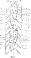
- each module 14 The two second grooves 20 located at the ends of each module 14 are formed so as to be joined to two lateral grooves 21.
- each second groove 20 of the two second grooves at the ends of each module is joined to a lateral groove 21 so as to form a single groove extending from the axially outermost edge of the tyre shoulder to the equatorial plane X-X, at least partially going beyond the latter.
- the two second grooves 20 located substantially at the ends of each module 14, in the embodiment shown in figure 2 have only one axial end 24 spaced away from the adjacent first groove 19 by a distance s to form a substantially continuous tread portion.
- each module 14 substantially extend in the central annular portion A between a pair of first grooves 19.
- Each inner second groove 20 further has both ends 24 spaced away from the adjacent first groove 19 by a distance s to form a substantially continuous tread portion.
- the axial spacing of the second grooves 20 from the first grooves 19 makes the tread band solid portions 27 substantially tied up with one another, ensuring stability when running on straight paths on roads, without compromising traction when running off-road.
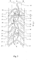
- tread band pattern of a second embodiment of a tyre according to the invention is shown.
- the module 14 comprises three second grooves 20 located substantially transversally with respect to the equatorial plane X-X; in particular two second grooves 20 located substantially at the ends of each module and an inner one comprised between the previous two.
- each second groove 20 located substantially at the ends of each module 14 are formed so as to be joined to two lateral grooves 21.
- each second groove 20 of the two second grooves at the ends of each module is joined to a lateral groove 21 so as to form a single ) groove extending from the axially outermost edge of the tyre shoulder to the equatorial plane X-X, at least partially going beyond the latter.
- each module 14 has only one axial end 24 spaced away from the adjacent first groove 19 by a distance s to form a substantially continuous tread portion.
- transverse second groove 20 having an ) inner location with respect to the two second grooves at the ends of each module 14 extends in the central annular portion A between a pair of first grooves 19.
- the inner transverse second groove 20 of each module 14 has both ends spaced away from the adjacent first groove 19 by a distance s to form a substantially continuous tread portion.
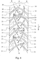
- a tread band pattern of a third embodiment of a tyre according to the invention is shown.
- the module 14 comprises three second grooves 20 and two pairs of first grooves 19.
- the three second grooves 20, two located substantially at the ends of the module 14 and an inner one, comprised between the previous two, are located substantially transversally with respect to the equatorial plane X-X.
- each module 14 there are two pairs of first grooves 19, and in each pair a groove 19 has greater extension than that of the other one.
- each module 14 the pairs of first grooves 19 are arranged so that each first groove 19 of lesser extension alternates in circumferential direction with a first groove 19 of greater extension.
- the second grooves 20 of each module 14 have both ends 24 spaced away from the adjacent first groove 19 by a distance s so as to form a substantially continuous tread portion.
- the axial spacing of the second grooves 20 from the first grooves 19 makes the tread band solid portions 27 substantially tied up with one another, ensuring stability when running on straight paths on roads, without compromising traction when running off-road.
- a tread band pattern of a further embodiment of a tyre according to the invention is shown.
- This embodiment is basically obtained by rotating the tread pattern of figure 2 by 180° and by setting new dimensions for the grooves, based on the size and curvature of the tyre for which the embodiment is intended.
- the Applicant carried out a series of tests on different kind of grounds with tyres according to the invention and comparison tyres. In particular, tests running off-road on not much demanding terrains (substantially dirt roads and/or gravel road), tests of traction on straight paths, tests of traction on bends, test of absorption of terrain bumps were carried out.
- test driver performed some typical manoeuvres on a track (predetermined off-road path). Afterwards, the test driver assessed the tyre behaviour and gave a score depending on the tyre performance during said manoeuvres.
- the Applicant also carried out a series of further tests on roads, always comparing the tyre according to the invention and the same kind of reference tyre used for the previous tests.
- test were carried out on a track on roads for assessing draining, stability, manoeuvrability and mileage.
- Table 2 shows the results obtained (in terms of deviation from the reference tyre, to which a value equal to 100 was conventionally given) by the tyres according to the invention.
- Table 2 COMPARISON TYRE INVENTION Front tyre draining 100 110 Rear tyre draining 100 110 Stability 100 100 Handling 100 100 Front tyre mileage 100 120 Rear tyre mileage 100 110
- the tyre according to the invention has a better behaviour as compared to the comparison tyre substantially in all of the assessed features.
- the new tyre turns out to be comparable, if not even slightly better in almost all of the assessed features as compared to the comparison tyre.
- the comparison tyre is one the best of its category, very much appreciated by the motorcyclists for its excellent features of drivability, grip, handling and stability both when running on roads an off-road.
- its tread band contributes to achieving a suitable contact surface in different driving condition (on straight paths and/or on bends), and ensures adequate water draining when running out of a track on wet asphalt.
Description
- The present invention relates to tyres for motorcycles. In particular, the present invention relates to tyres intended to be mounted on the front wheel and/or on the rear wheel of "big enduro or dual purpose" motorcycles having medium-large engine capacity (e.g. 600-1200 cm3 or higher), and/or medium-high power (e.g. about 70 hp or higher) and motorcycle mass in driving configuration for example equal to 150 kg or higher.
- Tyres for motorcycles are for example known from
US 4,364,426 andJP 61092903 -
US 4,364,426 describes a tyre for motorcycles having a tread provided with a plurality of spaced blocks defined by a plurality of first grooves spaced circumferentially and extending substantially diagonally across a tread. The first grooves channel water from the center of the tread and extend continuously from one tread edge to the other. Each first groove further comprises an intermediate portion which extends substantially circumferentially. The intermediate portions of two adjacent first grooves are spaced by a block defined by adjacent first grooves. -
JP 61092903 -
WO2009/153821 discloses a tyre according to the preamble of claim 1. - In recent times a trend has been observed to introduce into the market motorcycles for "big enduro or dual purpose" use having increasingly higher engine capacity and/or power, intended for mixed running conditions both on roads and off-road. In fact, for example, motorcycles for use on roads and off-road having an engine capacity of 1200 cm3, with powers of about 110 hp and motorcycle mass in driving configuration of about 240 kg are already present in the market.
- The tyres mounted on the wheels of such motorcycles shall ensure a stable behavior both when running on roads (for example, in towns, on motorways, on mountain roads with a large number of bends) and when running off-road, together with a high mileage.
- Excellent features of grip to the ground and traction are required from the tyres mounted on the aforesaid motorcycles, so that even considerable torques can be effectively transferred to the ground on different kind of terrains, and an effective braking action can be ensured. Moreover, such tyres shall ensure grip, roadholding and traction when running on wet ground and on off-road ground.
- Comfort and wear evenness features when running on roads are also required from such tyres. Reliability and performances on road surfaces with reduced grip are also required, being such tyres intended for a motorcycle class often used during the whole year..
- In the Applicant's experience, the aforesaid features are partially conflicting with one another, particularly in tyres for motorcycles intended for such different running conditions.
- The Applicant has noted that in practice a high traction of the tyre when running off-road may cause the tyre performances in terms of mileage and noise/vibrations to be reduced.
- The Applicant has further observed that better tyre performances for running on roads may cause the tyre performances in terms of traction, controllability and steerability on slippery, sandy and/or muddy terrains to be reduced.
- The Applicant has found a tread pattern suitable to meet the at least partially conflicting requirements mentioned above.
- Said tread pattern is provided in its central portion, substantially astride the equatorial plane, with a sequence of tread solid portions, circumferentially and axially delimited by deep grooves and at least for the most part substantially connected with one another and located so as to form a substantially continuous circumferential region, preferably extending over the whole tread band. By means of the aforesaid tread pattern the tyre is able to provide the desired performances in terms of traction and roadholding on dirt and rough grounds, and to provide performances in terms of grip and stability when running on roads, as well as water drainage on wet grounds in any running condition. The present invention is defined by a tyre according to claim 1. Preferred embodiments are defined by the dependent claims. Conveniently, the first grooves, as well as the second grooves, may have extensions different from one another.
- Advantageously, the first groove of lesser extension has an extension greater than or equal to the second groove of greatest extension.
- The Applicant has observed that such an arrangement and configuration of the second grooves allows good traction features in the longitudinal direction to be achieved, without reducing the grip effect of the central portion of the tread band and without causing excessive vibrations, noise and uneven wear phenomena. The Applicant is of the opinion that such an improvement is due to a proper balancing between the rate of corners formed by the outer edges of the second grooves, which ensure traction, and the rate of tread band solid portions with reduced mobility in the circumferential direction.
- The Applicant has further observed that by delimiting through the substantially circumferential first grooves the solid portions created in the module, a greater stiffness is provided to the central portion of the tread band, which is advantageous for reducing the tyre wear and for the driving stability. Moreover, in this way the traction of the tyre when running on off-road terrains at small lean angles of the vehicle is promoted.
- By tread band solid portion it is meant a tread band portion having a substantially zero void-to-rubber ratio, delimited by consecutive groove segments both in the axial and in the circumferential direction, wherein at least one of said segments is not connected with the previous one.
- By substantially continuous tread portion it is meant a tread portion substantially without relevant discontinuities which prevent the stress transmission to neighboring regions.
- By such expression it is meant to designate a tread portion, comprised between an end of a second groove and an adjacent segment of a first groove, in which the void-to-rubber ratio is substantially zero, as well as a tread portion, comprised between an end of a second groove and an adjacent segment of a first groove, in which the volume of rubber is greater by a predetermined amount, for example 50%, than the volume of rubber which one should remove for connecting said second groove with the segment of first groove.
- This volume of rubber can be thought, for example, as an ideal parallelepiped having a height defined by the distance s and a base defined by a rectangle having the width and the average depth of the second groove as its dimensions.
- Within the definition given above, therefore, fall both the case in which one or more thin (e.g. having an average width smaller than 2 mm) sipes are present between the end of a second groove and a segment of the first groove, and, for example, the case in which the end of the second groove is connected with the first groove and the connection segment has, for example, a noticeable depth reduction.
- By "tread pattern" it is meant the representation of each point of the tread band (grooves included) on a plane perpendicular to the equatorial plane of the tyre and tangent to the maximum diameter of the tyre. In the representation:
- in the axial direction the distance of each point of the tread band from the equatorial plane corresponds to the distance of such point from the equatorial plane measured on the axial development of the band itself;
- in the circumferential direction the distance between any two points of the tread band corresponds to the distance between the projections of the two points on the circumference corresponding to the maximum diameter of the tyre, the projection being obtained by means of radial planes passing at the two points.
- Angular measurements, and/or linear quantities (distances, widths, lengths, etc.), and/or areas are to be intended as referred to the tread pattern as defined above.
- Referring to the angular arrangement of the grooves formed in the tread band with respect to the equatorial plane of the tyre, such an angular arrangement is to be intended, for each point of the groove, as referred to the angle (between 0° and 180°) formed by a rotation made starting from the equatorial plane up to the direction tangent to the groove passing through that point. The rotation is meant to be performed by a vector initially lying along the direction defined, in the tread pattern, by the equatorial plane, and oriented opposite to the predetermined rotation direction of the tyre.
- The following definitions further apply:
- By "tyre for motorcycles" it is meant a tyre having a high curvature ratio (typically higher than 0.20), which allows high camber angles to be reached when running on a bend.
- By "equatorial plane" of the tyre it is meant a plane perpendicular to the rotation axis of the tyre and dividing the tyre into two symmetrically equal portions.
- By "circumferential" direction it is meant a direction generically directed according to the rotation direction of the tyre, or in any case only slightly inclined with respect to the rotation direction of the tyre.
- By "void-to-rubber ratio" it is meant the ratio between the total surface of the grooves of a determined portion of the tread pattern of the tyre (possibly of the whole tread pattern) and the total surface of the determined portion of the tread pattern (possibly of the whole tread pattern).
- By "axial development" of the tread band it is meant the length L of the arc defining the radially outermost profile of the tread band in a radial section of the tyre.
- By "curvature ratio" of the tyre it is meant the ratio between the distance of the radially highest point of the tread band from the maximum chord of the tyre, and the same maximum chord of the tyre, in a radial section of the tyre.
- By "average inclination of a groove" it is meant the arithmetical mean of the punctual inclinations of the groove itself with respect to the equatorial plane (X-X) measured along the extension of the groove.
- By "average depth of a groove" it is meant the arithmetical mean of the punctual depths of the groove itself measured along the extension of the groove.
- By "average width of a groove" it is meant the arithmetical mean of the punctual widths of the groove itself measured along the extension of the groove.
- Preferably, at least one of the second grooves has at least two ends, each spaced away from an adjacent first groove by said distance (s) so as to form a substantially continuous tread portion adapted to connect at least two tread band solid portions.
- Advantageously, the first groove of lesser extension has an extension greater than the second groove of greatest extension.
- For not making the central portion of the tyre excessively mobile and at the same time not reducing the draining effect in such portion, the first and the second grooves advantageously have an average depth smaller than 10 mm.
- Preferably, the first and the second grooves have an average depth greater than 4 mm in the case of a tyre intended to be mounted on the front wheel of a motorcycle and greater than 7 mm in the case of a tyre intended to be mounted on the rear wheel of a motorcycle.
- For providing a suitable amount of rubber between the end of a second groove and an adjacent segment of a first groove, the distance s is conveniently greater than 0,01 L.
- Preferably, the distance s is greater than or equal to 2 mm.
- For not excessively reducing the transverse extension of the second grooves, the distance s is conveniently smaller than 0,2 L.
- The aforesaid choice ensures a high rate of corners formed by the outer edges of the second grooves in the central annular portion (A), thus promoting traction in the circumferential direction.
- Preferably, the second grooves are the sole grooves which can break the substantial continuity in the circumferential direction of the tread band in the central annular portion (A).
- Preferably, between two circumferentially adjacent modules no further transverse grooves adapted to break the substantial continuity in the circumferential direction of the tread band in the central annular portion (A) are provided.
- Preferably, all of the axial ends of the second grooves are spaced away from the first grooves so as to form a tread portion substantially continuous in the circumferential direction.
- Advantageously, the second grooves comprise at least one first segment and at least one second segment inclined with respect to the first segment to form a convexity oriented discordantly with respect to the rolling direction of the tyre, in the case of a tyre intended to be mounted on the front wheel of a motorcycle, and concordantly with respect to the rolling direction of the tyre in the case of a tyre intended to be mounted on the rear wheel of a motorcycle.
- Advantageously, for providing a balanced driving on softer terrains, said first and second segments of the second grooves are inclined with respect to each other to form a vertex.
- Conveniently, the first segment of the second grooves is inclined with respect to the equatorial plane so as to form an angle α comprised in the range between 90° and 140° for the front tyre and comprised in the range between 0° and 45° for the rear tyre.
- Conveniently, the second segment of the second grooves is inclined with respect to the equatorial plane so as to form an angle P comprised in the range between 90° and 140° for the front tyre and comprised in the range between 0° and 40° for the rear tyre.
- Preferably, the first and second segments converging to form each vertex have the same orientation in the circumferential direction.
- Preferably, the first and second segments of the second grooves have different extensions.
- Conveniently, the vertexes of the second grooves are axially spaced away from the equatorial plane (X-X). The spacing in the axial direction of the vertexes of the second grooves increases the stiffness of the central portion at the equatorial plane and reduces the possibility of triggering uneven wear phenomena.
- Preferably, in each module the vertexes of two circumferentially consecutive second grooves are located axially on opposite sides with respect to the equatorial plane (X-X).
- This arrangement is advantageous, since the staggering of the vertexes reduces the noise while the tyre is in use. The aforesaid arrangement is preferably obtained by alternating in the circumferential direction the first and second segments of the second grooves present in each module.
- Preferably, the first segments of the second grooves have an extension greater than the second segments.
- Preferably, in each module at least two second grooves are located between two circumferential first grooves so as to cross the equatorial plane (X-X).
- Advantageously, the second grooves have an axial extension smaller than 0,4 L. Preferably, the second grooves have an axial extension smaller than 0,3 L.
- For ensuring a good traction in the central portion (A), the transverse second grooves have an axial extension greater than 0,1 L.
- Advantageously, in each module the first grooves of each pair are mutually staggered in the circumferential direction.
- Preferably, in each module the first grooves of each pair are mutually staggered in the circumferential direction at most by half the pitch.
- The staggered arrangement in the circumferential direction advantageously increases the stiffness of the tyre at the central portion (A).
- Conveniently, for reducing the triggering of uneven wear phenomena and the presence of points subjected to a high stress, in each module the first grooves of each pair of first grooves are arranged according to an arc of a circle.
- Conveniently, each shoulder portion (B) has an axial extension not greater than 40% of the axial development of the tread band, preferably an axial extension greater than 5% of the axial development of the tread band.
- Advantageously, each shoulder portion (B) may comprise a plurality of lateral grooves extending substantially transversally with respect to the equatorial plane (X-X).
- Advantageously, for ensuring a better wear resistance the lateral grooves are inclined with respect to the equatorial plane so as to have an average inclination relative to the equatorial plane (X-X), considered with reference to the rolling direction, smaller than 90° in the front tyre and greater than 90° in the rear tyre. Preferably, the axially inner end of the lateral grooves is located circumferentially substantially at the end of the second grooves.
- Advantageously, for each module at least one second groove is connected with a lateral groove.
- Preferably, for each module at least two second grooves are connected with two lateral grooves.
- Advantageously, for each module at least one lateral groove is connected with a first groove.
- Preferably, for each module at least two lateral grooves are connected with two first grooves.
- Further features and advantages of the tyre of the present invention will become more apparent from the following detailed description of some embodiments thereof, made hereafter with reference to the accompanying drawings by way of non-limiting example only. In the drawings:
-
figure 1 shows a radial sectional view of a tyre according to the invention; -
figure 2 shows a portion of the plan development of a portion of the tread band of a first embodiment of a front tyre according to the present invention; -
figure 3 shows a portion of the plan development of a portion of the tread band of a second embodiment of a front tyre according to the present invention; -
figure 4 shows a portion of the plan development of a portion of the tread band of a third embodiment of a front tyre according to the present invention; -
figure 5 shows a portion of the plan development of a portion of the tread band of a first embodiment of a rear tyre according to the present invention. - In
figure 1 a tyre for motorcycle wheels according to the present invention is generally indicated at 100. This tyre is preferably intended to be used on a wheel of a motorcycle of the "big enduro or dual purpose" segment. - An equatorial plane X-X and a rotation axis Z (not shown in the figures) are defined in the
tyre 100. Moreover, there are defined a circumferential direction (indicated in the figures by an arrow F pointing in the rotation direction of the tyre) and an axial direction, perpendicular to the equatorial plane X-X. - The
tyre 100 comprises acarcass structure 2 including at least onecarcass ply 3, made of an elastomeric material and comprising a plurality of reinforcing elements arranged parallel to one another. - The carcass ply 3 engages, by means of its opposite circumferential edges, at least one annular reinforcing structure 9.
- In particular, the opposite
lateral edges 3a of thecarcass ply 3 are turned up about annular reinforcing structures called bead rings. - A tapered elastomeric filling 5 taking up the space defined between the
carcass ply 3 and the respective turned uplateral edge 3a of thecarcass ply 3 is applied onto the axially outer perimeter edge of the bead rings 4. - As known, the tyre region comprising the
bead ring 4 and the filling 5 forms the so-called bead, intended for anchoring the tyre to a respective fitting rim, not shown. - The reinforcing elements included in the carcass ply 3 preferably comprise textile cords, selected from those usually adopted in the manufacture of carcasses for tyres, for example nylon, rayon, PET, PEN cords, with an elementary thread having a diameter between 0,35 mm and 1,5 mm.
- In an embodiment not shown, the carcass structure has its opposite lateral edges associated without a turn-up with special annular reinforcing structures provided with two annular inserts. A filling of elastomeric material may be located in an axially outer position with respect to the first annular insert. The second annular insert is instead located in an axially outer position with respect to the end of the carcass ply. Finally, in a axially outer position with respect to said second annular insert, and not necessarily in contact with the same, a further filling can be provided which terminates the formation of the annular reinforcing structure.
- A
belt structure 6 is circumferentially applied, in a radially outer position, onto thecarcass structure 2. Atread band 8 is circumferentially superimposed on thebelt structure 6. Longitudinal and/or transverse grooves, arranged so as to define a desired tread pattern, are typically formed on thetread band 8, further to a moulding operation carried out at the same time as the vulcanization of the tyre. - The
tyre 100 may comprise a pair of sidewalls laterally applied on opposite sides to saidcarcass structure 2. - The
tyre 100 has a straight section characterised by a high transverse curvature. - In particular, the
tyre 100 has a height H of the section, measured, at the equatorial plane, between the top of the tread band and the fitting diameter, defined by reference line r, passing through the tyre beads. Thetyre 100 further has a width C defined by the distance between the laterally opposite ends E of the tread itself, and a curvature defined by the specific value of the ratio between the distance f of the top of the tread from the line passing through the ends E of the tread itself, measured at the equatorial plane of the tyre, and the aforesaid width C. The ends E of the tread may be formed by a corner. - In the present description and in the subsequent claims, by tyres with high curvature tyres are meant which have a curvature ratio f/C not lower than 0,2, preferably f/C ≥ 0,25, for example equal to 0,28. Preferably, the curvature ratio f/C is not greater than 0,8, preferably f/C ≤ 0,5.
- Preferably, the tyres have particularly low sidewalls (
fig. 1 ). In other words, by tyres with low or lowered sidewalls tyres are meant in which the sidewall height ratio (H-f)/H is lower than 0,7, more preferably lower than 0,65, for example equal to 0,6 for the rear tyre and 0,5 for the front tyre. - The
carcass structure 2 is typically lined on its inner walls with a sealing layer, also called "liner", essentially consisting of a layer of an airproof elastomeric material, adapted to ensure the tight seal of the tyre itself after it has been inflated. - Preferably, the
belt structure 6 consists of alayer 7 having a plurality ofcircumferential windings 7a axially arranged in side-by-side relationship, formed by a rubberized cord or by a rubberized strip comprising a number (preferably, from two to five) of cords, spirally wound at an angle substantially equal to zero (typically between 0° and 5°) with respect to the equatorial plane X-X of the tyre. - Preferably, the belt structure extends over the whole crown portion of the tyre.
- In a preferred embodiment, the
belt structure 6 may consist of at least two radially superimposed layers, each consisting of elastomeric material reinforced with cords arranged parallel to one another. The layers are arranged so that the cords of the first belt layer are oriented obliquely with respect to the equatorial plane of the tyre, whereas the cords of the second layer also have an oblique orientation, but symmetrically crossed with respect to the cords of the first layer (so-called "cross-belt"). - In both cases, usually, the cords of the belt structure are textile or metal cords.
- Preferably, the
tyre 100 may comprise alayer 10 made of an elastomeric material, located between saidcarcass structure 2 and saidbelt structure 6 formed by said circumferential coils, saidlayer 10 preferably extending over a surface substantially corresponding to the surface on which thebelt structure 6 develops. Alternatively, saidlayer 10 extends over a surface smaller than the surface on which thebelt structure 6 develops, for example only over opposite lateral portions of the same. - In a further embodiment, an additional layer (not shown in
figure 1 ) made of an elastomeric material is located between saidbelt structure 6 and saidtread band 8, said layer preferably extending over a surface substantially corresponding to the surface on which saidbelt structure 6 develops. Alternatively, said layer extends only over at least a portion of the development of thebelt structure 6, for example over opposite lateral portions of the same. - In a preferred embodiment, at least one of said
layer 10 and said additional layer comprises short aramid fibers, for example made of Kevlar®, dispersed in said elastomeric material. - According to a feature of the invention, the
tread band 8 is divided into a central annular portion A and two shoulder annular portions B, symmetrically located with respect to the central annular portion. - The central annular portion A extends astride the equatorial plane X-X, over a width not greater than 65% of the axial development L of the
tread band 8, for example over a width equal to 60% of said axial development. - The Applicant has noted that usually when driving a so-called big enduro motorcycle the camber angles to which the tyre is subjected when used off-road are smaller than the camber angles to which the same tyre is subjected when used on roads.
- For this reason, the central annular portion A has a void-to-rubber ratio greater than the void-to-rubber ratio of the shoulder portions.
- In particular, the central annular portion A has a void-to-rubber ratio greater than 0,18, for example equal to about 0,19, and each shoulder portion B has a void-to-rubber ratio smaller than 0,18, for example equal to 0,16.
- In any case, the central annular portion A has a void-to-rubber ratio smaller than 25%.
- The central annular portion A has a tread pattern comprising a
module 14 repeated along a direction of circumferential development of the tyre. - In particular, in the embodiment shown in
figures 2 ,3 ,4 and5 themodule 14 is repeated astride the equatorial plane X-X. - The
module 14 has at least one pair offirst grooves 19, with substantially circumferential course, at least partially located on opposite sides with respect to the equatorial plane X-X. - Preferably, each
first groove 19 extends only within the central annular portion A, in particular between the equatorial plane X-X and a shoulder portion B. - Conveniently, the
first grooves 19, as well as thesecond grooves 20, may have extensions different from one another. - Advantageously, the groove of lesser extension between the
first grooves 19 has an extension greater than or equal to that of the groove having the greatest extension between thesecond grooves 20. - Preferably, the groove of lesser extension between the
first grooves 19 has an extension greater than that of the groove having the greatest extension between thesecond grooves 20. - The
first grooves 19 have a draining function in the central annular portion A and therefore they have a circumferential extension greater than 1% of the total circumferential development of the tyre. - Preferably, each first groove has a circumferential extension smaller than 15% of the total circumferential development of the tyre.
- Advantageously, each first groove has a circumferential extension smaller than 300 mm.
- The
first grooves 19 of each pair are mutually staggered in the circumferential direction. The circumferentially staggered arrangement of thefirst grooves 19 is embodied in particular as circumferentially staggered arrangement of the axially innermost ends of thefirst grooves 19. - Preferably, the
first grooves 19 are staggered in the circumferential direction at most by half the pitch. - This choice for the arrangement and extension of the
first grooves 19 contributes to increasing the stiffness of the central annular portion A, reducing the mobility of the tread bandsolid portions 27, hereinafter described in more detail. - The
first grooves 19 have a width greater than 1,5 mm, preferably smaller than 9 mm. - The
first grooves 19 of eachmodule 14 have a width that varies in the circumferential direction. In particular, in the case of tyres mounted on the front wheel of a motorcycle thefirst grooves 19 have a width which decreases in the same direction as the rolling direction of the tyre, indicated by arrow F infigures 2 ,3 and4 . - Vice versa, in the case of tyres intended to be mounted on the rear wheels of a motorcycle, the
first grooves 19 have a width which decreases in a direction opposite to the rolling direction F of the tyre, as shown infigure 5 . - For ensuring an effective draining action in the central annular portion A, preferably the
first grooves 19 have an average depth greater than 4 mm in the case of a tyre intended to be mounted on the front wheel of a motorcycle, and greater than 7 mm in the case of a tyre intended to be mounted on the rear wheel of a motorcycle. - For reducing the presence of points which trigger critical stresses, preferably the
first grooves 19 of each pair are arranged along an arc of a circle. - The
module 14 further comprises at least two, preferably three, substantially transversesecond grooves 20 which cross the equatorial plane X-X. - The transverse
second grooves 20 define in each module, together with thefirst grooves 19, tread bandsolid portions 27. - The
second grooves 20 are arranged so as to have at least one axial end spaced away from the adjacentfirst groove 19. - As in the embodiments shown in
figures 2-5 , thesecond grooves 20, and particularly at least oneaxial end 24 thereof, is spaced away from afirst groove 19 by a distance s so as to form a substantially continuous tread portion adapted to connect at least two tread bandsolid portions 27. - Preferably, the
second grooves 20 neither intersect nor touch thefirst grooves 19 so as to form a substantially continuous circumferential annular portion. The substantially continuous circumferential annular portion is represented by the sequence ofsolid portions 27 connected by the "bridges" formed by the spacing between theends 24 of thesecond grooves 20 and the adjacentfirst grooves 19. - Each tread band
solid portion 27 is thus represented by a portion of the tread band with substantially zero void-to-rubber ratio, delimited by segments offirst grooves 19 in the axial direction and bysecond grooves 20 or segments thereof in the circumferential direction. - At least one
second groove 20 in eachmodule 14 has the two axially outer ends 24 spaced away from an adjacentfirst groove 19 by the distance (s) so as to form a substantially continuous tread portion adapted to connect at least two tread bandsolid portions 27. - For providing, between the
end 24 of asecond groove 20 and an adjacent segment of afirst groove 19, an amount of rubber suitable to reduce the mobility of the tread bandsolid portions 27, the distance s is conveniently greater than 0,01 L. - Preferably, the distance s is greater than or equal to 5 mm.
- In order to avoid excessively reducing the transverse extension of the
second grooves 20, the distance s is conveniently smaller than 0,2 L. - Preferably, the
second grooves 20 are the sole grooves which can break the substantial continuity in the circumferential direction of the tread band in the central annular portion A. - In other words, between two circumferentially
adjacent modules 14 no further transverse grooves adapted to break the substantial continuity in the circumferential direction of the tread band in the central annular portion A are provided. - The
second grooves 20 have a lesser extension than that of thefirst grooves 19. - The
second grooves 20 comprise at least onefirst segment 22 and at least onesecond segment 23 inclined with respect to thefirst segment 22 to form a convexity with a discordant, preferably opposite, orientation with respect to the rolling direction of the tyre, in the case of tyres intended to be mounted on the front wheel of a motorcycle. - Vice versa, in the case of tyres intended to be mounted on the rear wheel of a motorcycle, as in the embodiment of
figure 5 , thesecond grooves 20 comprise at least onefirst segment 22 and at least onesecond segment 23 inclined with respect to thefirst segment 22 to form a convexity with a concordant orientation with respect to the rolling direction of the tyre (arrow F infigure 5 ). - Conveniently, the
first segment 22 of the second grooves is inclined with respect to the equatorial plane so as to form an angle α comprised in the range between 90° and 140° for the front tyre and comprised in the range between 0° and 45° for the rear tyre. - Conveniently, the
second segment 23 of the second grooves is inclined with respect to the equatorial plane so as to form an angle β comprised in the range between 90° and 140° for the front tyre and comprised in the range between 0° and 40° for the rear tyre. - The aforesaid choice increases the rate of corner portion of the
second grooves 20, with advantage to the traction of the central annular portion A. - Preferably, as in the embodiments shown in
figures 2-5 , in order to provide a balanced driving on softer terrains, the first 22 and thesecond segment 23 are inclined with respect to each other to form avertex 29. - Referring to the embodiments shown in
figures 2-5 , all of thevertexes 29 have the same orientation in the circumferential direction. - The
vertexes 29 are axially spaced away from the equatorial plane X-X. - The aforesaid choice contributes to increasing the stiffness of the central annular portion A exactly at the equatorial plane X-X and to avoiding, or in any case reducing, the risk of triggering uneven wear phenomena at the
vertexes 29 themselves. - Preferably, in a
same module 14 thevertexes 29 of two circumferentially adjacent or consecutivesecond grooves 20 are located axially on opposite sides with respect to the equatorial plane X-X. - Such an arrangement of the
vertexes 29 is obtained thanks to the different extension of thefirst segments 22 and thesecond segments 23 of thesecond grooves 20. - Preferably, in each
module 14 the segment of lesser extension of asecond groove 20 is positioned on an opposite side relative to the equatorial plane X-X with respect to the segment of lesser extension of the circumferentially adjacent second groove. - Preferably, the
second grooves 20 have an average depth greater than 4 mm in the case of a tyre intended to be mounted on the front wheel of a motorcycle and greater than 7 mm in the case of a tyre intended to be mounted on the rear wheel of a motorcycle. - The
second grooves 20 have an average width greater than 4 mm, preferably smaller than 12 mm - Preferably, the
second grooves 20 have an average width which varies along their extension. - Each shoulder portion B has an axial extension not greater than 40%, and preferably not smaller than 5%, of the axial development L of the
tread band 8 and comprises a plurality oflateral grooves 21 extending substantially transversally with respect to the equatorial plane X-X. - Preferably, as in the embodiments shown in
figures 2-5 , in the case of the front tyre thelateral grooves 21 are inclined with respect to the equatorial plane of the tyre so as to form an angle greater than 90°, preferably smaller than 140°. - In the rear tyre the
lateral grooves 21 are inclined with respect to the equatorial plane of the tyre so as to form an angle comprised in the range between 0° and 40°. - The
lateral grooves 21 of a first shoulder portion B are arranged substantially in the same way as thelateral grooves 21 of the other shoulder portion B. - In order to promote the draining of water, the
lateral grooves 21 have a variable width along their extension and particularly an average width which increases moving axially from the centre of the tyre towards the axially outer shoulder edge. - For ensuring an effective draining, the
lateral grooves 21 have a greater depth close to the central annular portion A. - Preferably, the depth of the
lateral grooves 21 at the end close to the central annular portion is greater than 4 mm. - In
Fig. 2 a tread band pattern of a first embodiment of a tyre according to the invention, particularly adapted to be mounted on the front wheel of a motorcycle, is shown. - The
module 14 comprises foursecond grooves 20 located substantially transversally with respect to the equatorial plane X-X. - The two
second grooves 20 located at the ends of eachmodule 14 are formed so as to be joined to twolateral grooves 21. In detail, eachsecond groove 20 of the two second grooves at the ends of each module is joined to alateral groove 21 so as to form a single groove extending from the axially outermost edge of the tyre shoulder to the equatorial plane X-X, at least partially going beyond the latter. - The two
second grooves 20 located substantially at the ends of eachmodule 14, in the embodiment shown infigure 2 , have only oneaxial end 24 spaced away from the adjacentfirst groove 19 by a distance s to form a substantially continuous tread portion. - Still referring to the embodiment shown in
figure 2 , the two innersecond grooves 20 of eachmodule 14 substantially extend in the central annular portion A between a pair offirst grooves 19. Each innersecond groove 20 further has both ends 24 spaced away from the adjacentfirst groove 19 by a distance s to form a substantially continuous tread portion. - The axial spacing of the
second grooves 20 from thefirst grooves 19 makes the tread bandsolid portions 27 substantially tied up with one another, ensuring stability when running on straight paths on roads, without compromising traction when running off-road. - In
Fig. 3 tread band pattern of a second embodiment of a tyre according to the invention, particularly adapted to be mounted on the front wheel of a motorcycle, is shown. - In this embodiment the
module 14 comprises threesecond grooves 20 located substantially transversally with respect to the equatorial plane X-X; in particular twosecond grooves 20 located substantially at the ends of each module and an inner one comprised between the previous two. - The two
second grooves 20 located substantially at the ends of eachmodule 14 are formed so as to be joined to twolateral grooves 21. In detail, eachsecond groove 20 of the two second grooves at the ends of each module is joined to alateral groove 21 so as to form a single ) groove extending from the axially outermost edge of the tyre shoulder to the equatorial plane X-X, at least partially going beyond the latter. - The two transverse
second grooves 20 at the ends of eachmodule 14 have only oneaxial end 24 spaced away from the adjacentfirst groove 19 by a distance s to form a substantially continuous tread portion. - Vice versa, the transverse
second groove 20 having an ) inner location with respect to the two second grooves at the ends of eachmodule 14 extends in the central annular portion A between a pair offirst grooves 19. - The inner transverse
second groove 20 of eachmodule 14 has both ends spaced away from the adjacentfirst groove 19 by a distance s to form a substantially continuous tread portion. - In
Fig. 4 a tread band pattern of a third embodiment of a tyre according to the invention, particularly adapted to be mounted on the front wheel of a motorcycle, is shown. - In this embodiment the
module 14 comprises threesecond grooves 20 and two pairs offirst grooves 19. - The three
second grooves 20, two located substantially at the ends of themodule 14 and an inner one, comprised between the previous two, are located substantially transversally with respect to the equatorial plane X-X. - In each
module 14, as mentioned above, there are two pairs offirst grooves 19, and in each pair agroove 19 has greater extension than that of the other one. - For ensuring a substantially symmetrical distribution of the
first grooves 19 in the circumferential direction, thus favouring a greater behaviour stability of the tyre, in eachmodule 14 the pairs offirst grooves 19 are arranged so that eachfirst groove 19 of lesser extension alternates in circumferential direction with afirst groove 19 of greater extension. - In this embodiment the
second grooves 20 of eachmodule 14 have both ends 24 spaced away from the adjacentfirst groove 19 by a distance s so as to form a substantially continuous tread portion. - Also in this case, the axial spacing of the
second grooves 20 from thefirst grooves 19 makes the tread bandsolid portions 27 substantially tied up with one another, ensuring stability when running on straight paths on roads, without compromising traction when running off-road. - In
Fig. 5 a tread band pattern of a further embodiment of a tyre according to the invention, particularly adapted to be mounted on the rear wheel of a motorcycle, is shown. - This embodiment is basically obtained by rotating the tread pattern of
figure 2 by 180° and by setting new dimensions for the grooves, based on the size and curvature of the tyre for which the embodiment is intended. - The Applicant carried out a series of tests on different kind of grounds with tyres according to the invention and comparison tyres. In particular, tests running off-road on not much demanding terrains (substantially dirt roads and/or gravel road), tests of traction on straight paths, tests of traction on bends, test of absorption of terrain bumps were carried out.
- In the tests tyres were compared having size 110/80
R 19, with the same compound and carcass and belt structure, mounted on the wheels of a BMW R1200 GS. Tyres of the model Tourance EXPTM (comparison) were compared with tyres (invention) comprising a tread band having a pattern as that shown in previousfigure 2 . - In order to assess the aforesaid parameters, the test driver performed some typical manoeuvres on a track (predetermined off-road path). Afterwards, the test driver assessed the tyre behaviour and gave a score depending on the tyre performance during said manoeuvres.
- The results of these tests are expressed by means of an assessment scale representing the subjective judgment expressed by the test driver by means of a score system. The values reported in the following table represent an average of the values obtained in many test sessions (5 - 6 tests) and provided by several test drivers. Table 1 shows the results obtained (in terms of deviation from the reference tyre, to which a value equal to 100 was conventionally given) by the tyres according to the invention.
Table 1 COMPARISON TYRE INVENTION Running off-road on not much demanding terrains 100 100 Traction on straight paths 100 110 Traction on bends 100 100 Absorption of terrain bumps 100 95 - The Applicant also carried out a series of further tests on roads, always comparing the tyre according to the invention and the same kind of reference tyre used for the previous tests.
- In particular, test were carried out on a track on roads for assessing draining, stability, manoeuvrability and mileage.
- The size of the tyres and the kind of motorcycle were the same as in the previous off-road tests.
- Table 2 shows the results obtained (in terms of deviation from the reference tyre, to which a value equal to 100 was conventionally given) by the tyres according to the invention.
Table 2 COMPARISON TYRE INVENTION Front tyre draining 100 110 Rear tyre draining 100 110 Stability 100 100 Handling 100 100 Front tyre mileage 100 120 Rear tyre mileage 100 110 - The tyre according to the invention has a better behaviour as compared to the comparison tyre substantially in all of the assessed features.
- As it can be noted, keeping other structural features of tyre the same, the contribution given by the tread pattern turns out to be important for the tyre behaviour both when running on roads and when running off-roads.
- In fact, the new tyre turns out to be comparable, if not even slightly better in almost all of the assessed features as compared to the comparison tyre. In this respect it is recalled that the comparison tyre is one the best of its category, very much appreciated by the motorcyclists for its excellent features of drivability, grip, handling and stability both when running on roads an off-road.
- In particular, its tread band contributes to achieving a suitable contact surface in different driving condition (on straight paths and/or on bends), and ensures adequate water draining when running out of a track on wet asphalt.
- The present invention has been described with reference to some embodiments thereof. Many modifications can be made in the embodiments described in detail, still remaining within the scope of protection of the invention, defined by the following claims.
Claims (27)
- Tyre (100) for motorcycles, having a tread band (8) comprising a central annular portion (A) symmetrically located astride an equatorial plane (X-X) and two shoulder annular portions (B) located on axially opposite sides with respect to the central annular portion (A);
the tread band (8) having a void-to-rubber ratio not greater than 25%;
the central annular portion (A) having an axial extension not greater than 65% of the axial development of the tread band (8) and said central portion (A) having at least one module (14) circumferentially repeated;
each shoulder portion (B) having an axial extension not greater than 40% of the axial development of the tread band (8);
said module (14) comprising at least one pair of first grooves (19) with substantially circumferential course, at least partially located on opposite sides with respect to the equatorial plane (X-X),
wherein
the central annular portion (A) has a void-to-rubber ratio not smaller than 10% and said module (14) comprises a plurality of second grooves (20) located substantially transversally with respect to the equatorial plane (X-X), said tyre being characterized in that in a same module (14) at least one second groove (20) is located completely between two first grooves (19) so as to cross the equatorial plane (X-X); said substantially transverse second grooves (20) defining in each module together with said substantially circumferential first grooves (19) at least two tread band solid portions (27),
said second grooves (20) having at least one end (24) spaced away from an adjacent first groove (19) by a distance (s) so as to form a substantially continuous tread portion adapted to connect at least two tread band solid portions (27). - Tyre (100) according to claim 1, wherein the first groove (19) of lesser extension has an extension greater than or equal to the second groove (20) of greatest extension.
- Tyre (100) according to claim 1, wherein at least one of said second grooves (20) has at least two ends (24), each spaced away from an adjacent first groove (19) by said distance (s) so as to form a substantially continuous tread portion adapted to connect at least two tread band solid portions.
- Tyre (100) according to claim 1, wherein the first (19) and the second grooves (20) have an average depth smaller than 10 mm.
- Tyre (100) according to any one of the previous claims 1 to 4, wherein said distance s is greater than 0,01 L, where L is the length of the arc defining the radially outermost profile of the tread band in a radial section of the tyre.
- Tyre (100) according to claim 5, wherein said distance s is smaller than 0,2 L.
- Tyre (100) according to any one of the previous claims 1 to 6, wherein all of the axial ends of the second grooves (20) are spaced away from the first grooves (19) so as to form a tread portion substantially continuous in a circumferential direction.
- Tyre (100) according to any one of the previous claims 1 to 7, wherein the second grooves (20) comprise at least one first (22) and at least one second segment (23) inclined with respect to the said first segment (22) to form a convexity oriented oppositely to the rolling direction of the tyre, in the case of a tyre intended to be mounted on the front wheel of a motorcycle.
- Tyre (100) according to claim 8, wherein the first and the second segment (22 and 23) of the second grooves (20) have a different extension.
- Tyre (100) according to any one of the previous claims 1 to 9, wherein the second grooves (20) comprise at least one first (22) and at least one second segment (23) inclined with respect to the first segment (22) to form a vertex (29).
- Tyre (100) according to claim 9, wherein the said vertexes (29) have all the same orientation in a circumferential direction.
- Tyre (100) according to claim 10 or 11, wherein the said vertexes (29) are axially spaced away from the equatorial plane (X-X).
- Tyre (100) according to any one of the previous claims 10 to 12, wherein in a same module (14) the vertexes (29) of two circumferentially consecutive second grooves (20) are located axially on opposite sides with respect to the equatorial plane (X-X).
- Tyre (100) according to any one of the previous claims 5 to 13, wherein the second grooves (20) have an axial extension smaller than 0,4 L.
- Tyre (100) according to any one of the previous claims 5 to 14, wherein the second grooves (20) have an axial extension greater than 0,1 L.
- Tyre (100) according to claim 1, wherein each first groove (19) has a circumferential extension smaller than 15% of the total circumferential development of the tyre.
- Tyre (100) according to claim 1, wherein each first groove (19) has a circumferential extension smaller than 300 mm.
- Tyre (100) according to any one of the previous claims 1 to 17, wherein in each module (14) the first grooves (19) of each pair are mutually staggered in a circumferential direction.
- Tyre (100) according to claim 18, wherein in each module (14) the first grooves (19) of each pair are mutually staggered in a circumferential direction at most by half the pitch.
- Tyre (100) according to any one of the previous claims 1 to 19, wherein in each module (14) the first grooves (19) of each pair are arranged according to an arc of a circle.
- Tyre (100) according to any one of the previous claims 8 to 20, wherein the first segment of the second grooves is inclined with respect to the equatorial plane so as to form an angle (α) in the range between 90° and 140° for the front tyre.
- Tyre (100) according to any one of the previous claims 8 to 21, wherein the first segment of the second grooves is inclined with respect to the equatorial plane (X-X) so as to form an angle (α) in the range between 0° and 45° for the rear tyre.
- Tyre (100) according to any one of the previous claims 8 to 22, wherein the second segment of the second grooves is inclined with respect to the equatorial plane (X-X) so as to form an angle (β) in the range between 90° and 140° for the front tyre.
- Tyre (100) according to any one of the previous claims 8 to 23, wherein the second segment of the second grooves is inclined with respect to the equatorial plane (X-X) so as to form an angle (β) in the range between 0° and 40° for the rear tyre.
- Tyre (100) according to any one of the previous claims 1 to 24, wherein for each module (14) at least one second groove (20) is connected with a lateral groove (21).
- Tyre (100) according to any one of the previous claim 25, wherein the lateral grooves (21) have a depth greater than 4 mm at the end close to the central annular portion.
- Tyre (100) according to any one of the previous claims 25 to 26, wherein for each module (14) at least two second grooves (20) are connected with two lateral grooves (21).
Applications Claiming Priority (3)
| Application Number | Priority Date | Filing Date | Title |
|---|---|---|---|
| ITRM20110513 | 2011-09-29 | ||
| US201161581052P | 2011-12-28 | 2011-12-28 | |
| PCT/IB2012/001909 WO2013046004A2 (en) | 2011-09-29 | 2012-09-27 | Tyre for motorcycles |
Publications (2)
| Publication Number | Publication Date |
|---|---|
| EP2760682A2 EP2760682A2 (en) | 2014-08-06 |
| EP2760682B1 true EP2760682B1 (en) | 2017-11-08 |
Family
ID=44993769
Family Applications (1)
| Application Number | Title | Priority Date | Filing Date |
|---|---|---|---|
| EP12790630.3A Active EP2760682B1 (en) | 2011-09-29 | 2012-09-27 | Tyre for motorcycles |
Country Status (6)
| Country | Link |
|---|---|
| US (1) | US9610808B2 (en) |
| EP (1) | EP2760682B1 (en) |
| JP (1) | JP6081467B2 (en) |
| CN (1) | CN103930285B (en) |
| BR (1) | BR112014006584B1 (en) |
| WO (1) | WO2013046004A2 (en) |
Families Citing this family (11)
| Publication number | Priority date | Publication date | Assignee | Title |
|---|---|---|---|---|
| JP5824490B2 (en) * | 2013-09-20 | 2015-11-25 | 住友ゴム工業株式会社 | Motorcycle tires |
| JP6487702B2 (en) * | 2015-01-30 | 2019-03-20 | 住友ゴム工業株式会社 | Pneumatic tires for motorcycles |
| EP3330102B1 (en) * | 2015-07-31 | 2019-12-18 | Bridgestone Corporation | Pneumatic tire for motorcycles |
| ITUB20154585A1 (en) * | 2015-10-12 | 2017-04-12 | Pirelli | MOTORCYCLE WHEEL TIRE. |
| CN108349318B (en) | 2015-11-04 | 2021-02-26 | 倍耐力轮胎股份公司 | Tyre for motorcycle wheels |
| ITUB20154793A1 (en) * | 2015-11-04 | 2017-05-04 | Pirelli | MOTORCYCLE WHEEL TIRE. |
| CN109922975B (en) | 2016-09-28 | 2021-03-12 | 倍耐力轮胎股份公司 | Motorcycle tyre |
| EP3741583B1 (en) * | 2016-10-28 | 2022-02-23 | Pirelli Tyre S.p.A. | Motorcycle tyre |
| IT201800007188A1 (en) * | 2018-07-13 | 2020-01-13 | Vehicle wheel tire | |
| CN113165443B (en) * | 2018-11-30 | 2023-03-28 | 倍耐力轮胎股份公司 | Motorcycle tyre |
| JP2023135401A (en) * | 2022-03-15 | 2023-09-28 | 住友ゴム工業株式会社 | Motorcycle tire |
Family Cites Families (16)
| Publication number | Priority date | Publication date | Assignee | Title |
|---|---|---|---|---|
| US4364426A (en) | 1981-03-26 | 1982-12-21 | Dunlop Tire & Rubber Corporation | Motorcycle tire tread |
| JPS6045404A (en) * | 1983-08-24 | 1985-03-11 | Bridgestone Corp | Tyre pattern having high wet-skid resistance |
| JPS6192903A (en) | 1984-10-13 | 1986-05-10 | Sumitomo Rubber Ind Ltd | Tyre pattern of on-and-off running motorcycle |
| JPH05201207A (en) * | 1992-01-27 | 1993-08-10 | Bridgestone Corp | Pneumatic tire for motorcycle |
| JPH08188016A (en) * | 1995-01-09 | 1996-07-23 | Yokohama Rubber Co Ltd:The | Tire for motor cycle |
| CA2506071A1 (en) * | 2002-12-19 | 2004-07-08 | Pirelli Pneumatici S.P.A. | Tread pattern for winter tires |
| JP2005138807A (en) * | 2003-11-10 | 2005-06-02 | Sumitomo Rubber Ind Ltd | Tire for motorcycle rear wheel |
| JP5013759B2 (en) | 2006-06-15 | 2012-08-29 | 株式会社ブリヂストン | Motorcycle tires |
| US9150055B2 (en) * | 2007-11-06 | 2015-10-06 | Pirelli Tyre S.P.A. | Motorcycle tyre |
| WO2009144801A1 (en) | 2008-05-29 | 2009-12-03 | 富士通株式会社 | Dithiane derivative, polymer, resist composition, and process for producing semiconductor using the resist composition |
| WO2009153821A1 (en) | 2008-06-20 | 2009-12-23 | Pirelli Tyre S.P.A. | Motorcycle tyre |
| CN102066134B (en) * | 2008-06-20 | 2013-12-25 | 倍耐力轮胎股份公司 | Motorcycle tyre |
| US9145031B2 (en) * | 2008-12-24 | 2015-09-29 | Pirelli Tyre S.P.A. | Tyres for motor vehicles |
| US10035381B2 (en) * | 2009-07-28 | 2018-07-31 | Pirelli Tyre S.P.A. | Motor vehicle tyre |
| JP5193166B2 (en) * | 2009-12-08 | 2013-05-08 | 住友ゴム工業株式会社 | Motorcycle tires |
| WO2011080566A1 (en) * | 2009-12-29 | 2011-07-07 | Pirelli Tyre S.P.A | Motorcycle tyre and pair of motorcycle tyres |
-
2012
- 2012-09-27 BR BR112014006584-5A patent/BR112014006584B1/en active IP Right Grant
- 2012-09-27 EP EP12790630.3A patent/EP2760682B1/en active Active
- 2012-09-27 CN CN201280045997.1A patent/CN103930285B/en active Active
- 2012-09-27 US US14/346,430 patent/US9610808B2/en active Active
- 2012-09-27 JP JP2014532489A patent/JP6081467B2/en active Active
- 2012-09-27 WO PCT/IB2012/001909 patent/WO2013046004A2/en active Application Filing
Non-Patent Citations (1)
| Title |
|---|
| None * |
Also Published As
| Publication number | Publication date |
|---|---|
| WO2013046004A3 (en) | 2013-07-04 |
| US9610808B2 (en) | 2017-04-04 |
| JP6081467B2 (en) | 2017-02-15 |
| JP2015502279A (en) | 2015-01-22 |
| EP2760682A2 (en) | 2014-08-06 |
| CN103930285A (en) | 2014-07-16 |
| WO2013046004A2 (en) | 2013-04-04 |
| BR112014006584B1 (en) | 2020-10-20 |
| BR112014006584A2 (en) | 2017-04-04 |
| US20140230978A1 (en) | 2014-08-21 |
| CN103930285B (en) | 2017-06-13 |
Similar Documents
| Publication | Publication Date | Title |
|---|---|---|
| EP2760682B1 (en) | Tyre for motorcycles | |
| EP2741926B1 (en) | Tyre for motorcycles | |
| EP2459396B1 (en) | Pair of motor vehicle tyres | |
| EP2307207B1 (en) | Motorcycle tyre | |
| US10919343B2 (en) | Tyre for motorcyle wheels | |
| EP2459395B1 (en) | Motor vehicle tyre | |
| EP2797758B1 (en) | Pneumatic tire for motorcycle | |
| US11040574B2 (en) | Tyre for motorcyle wheels | |
| EP2459394B1 (en) | Motor vehicle tyre | |
| CN109843607B (en) | Motorcycle tyre | |
| US11059329B2 (en) | Tyre for motorcycle wheels | |
| EP3744540B1 (en) | Tyre for motorcycle wheels | |
| EP2265450A1 (en) | Heavy- load vehicle tire | |
| EP2797757B1 (en) | Tyre for motorcycles |
Legal Events
| Date | Code | Title | Description |
|---|---|---|---|
| PUAI | Public reference made under article 153(3) epc to a published international application that has entered the european phase |
Free format text: ORIGINAL CODE: 0009012 |
|
| 17P | Request for examination filed |
Effective date: 20140422 |
|
| AK | Designated contracting states |
Kind code of ref document: A2 Designated state(s): AL AT BE BG CH CY CZ DE DK EE ES FI FR GB GR HR HU IE IS IT LI LT LU LV MC MK MT NL NO PL PT RO RS SE SI SK SM TR |
|
| DAX | Request for extension of the european patent (deleted) | ||
| 17Q | First examination report despatched |
Effective date: 20160519 |
|
| STAA | Information on the status of an ep patent application or granted ep patent |
Free format text: STATUS: EXAMINATION IS IN PROGRESS |
|
| GRAP | Despatch of communication of intention to grant a patent |
Free format text: ORIGINAL CODE: EPIDOSNIGR1 |
|
| STAA | Information on the status of an ep patent application or granted ep patent |
Free format text: STATUS: GRANT OF PATENT IS INTENDED |
|
| INTG | Intention to grant announced |
Effective date: 20170607 |
|
| GRAS | Grant fee paid |
Free format text: ORIGINAL CODE: EPIDOSNIGR3 |
|
| GRAA | (expected) grant |
Free format text: ORIGINAL CODE: 0009210 |
|
| STAA | Information on the status of an ep patent application or granted ep patent |
Free format text: STATUS: THE PATENT HAS BEEN GRANTED |
|
| AK | Designated contracting states |
Kind code of ref document: B1 Designated state(s): AL AT BE BG CH CY CZ DE DK EE ES FI FR GB GR HR HU IE IS IT LI LT LU LV MC MK MT NL NO PL PT RO RS SE SI SK SM TR |
|
| REG | Reference to a national code |
Ref country code: GB Ref legal event code: FG4D |
|
| REG | Reference to a national code |
Ref country code: CH Ref legal event code: EP Ref country code: AT Ref legal event code: REF Ref document number: 943776 Country of ref document: AT Kind code of ref document: T Effective date: 20171115 |
|
| REG | Reference to a national code |
Ref country code: IE Ref legal event code: FG4D |
|
| REG | Reference to a national code |
Ref country code: DE Ref legal event code: R096 Ref document number: 602012039556 Country of ref document: DE |
|
| REG | Reference to a national code |
Ref country code: NL Ref legal event code: MP Effective date: 20171108 |
|
| REG | Reference to a national code |
Ref country code: LT Ref legal event code: MG4D |
|
| REG | Reference to a national code |
Ref country code: AT Ref legal event code: MK05 Ref document number: 943776 Country of ref document: AT Kind code of ref document: T Effective date: 20171108 |
|
| PG25 | Lapsed in a contracting state [announced via postgrant information from national office to epo] |
Ref country code: LT Free format text: LAPSE BECAUSE OF FAILURE TO SUBMIT A TRANSLATION OF THE DESCRIPTION OR TO PAY THE FEE WITHIN THE PRESCRIBED TIME-LIMIT Effective date: 20171108 Ref country code: SE Free format text: LAPSE BECAUSE OF FAILURE TO SUBMIT A TRANSLATION OF THE DESCRIPTION OR TO PAY THE FEE WITHIN THE PRESCRIBED TIME-LIMIT Effective date: 20171108 Ref country code: NL Free format text: LAPSE BECAUSE OF FAILURE TO SUBMIT A TRANSLATION OF THE DESCRIPTION OR TO PAY THE FEE WITHIN THE PRESCRIBED TIME-LIMIT Effective date: 20171108 Ref country code: ES Free format text: LAPSE BECAUSE OF FAILURE TO SUBMIT A TRANSLATION OF THE DESCRIPTION OR TO PAY THE FEE WITHIN THE PRESCRIBED TIME-LIMIT Effective date: 20171108 Ref country code: NO Free format text: LAPSE BECAUSE OF FAILURE TO SUBMIT A TRANSLATION OF THE DESCRIPTION OR TO PAY THE FEE WITHIN THE PRESCRIBED TIME-LIMIT Effective date: 20180208 Ref country code: FI Free format text: LAPSE BECAUSE OF FAILURE TO SUBMIT A TRANSLATION OF THE DESCRIPTION OR TO PAY THE FEE WITHIN THE PRESCRIBED TIME-LIMIT Effective date: 20171108 |
|
| PG25 | Lapsed in a contracting state [announced via postgrant information from national office to epo] |
Ref country code: AT Free format text: LAPSE BECAUSE OF FAILURE TO SUBMIT A TRANSLATION OF THE DESCRIPTION OR TO PAY THE FEE WITHIN THE PRESCRIBED TIME-LIMIT Effective date: 20171108 Ref country code: LV Free format text: LAPSE BECAUSE OF FAILURE TO SUBMIT A TRANSLATION OF THE DESCRIPTION OR TO PAY THE FEE WITHIN THE PRESCRIBED TIME-LIMIT Effective date: 20171108 Ref country code: GR Free format text: LAPSE BECAUSE OF FAILURE TO SUBMIT A TRANSLATION OF THE DESCRIPTION OR TO PAY THE FEE WITHIN THE PRESCRIBED TIME-LIMIT Effective date: 20180209 Ref country code: HR Free format text: LAPSE BECAUSE OF FAILURE TO SUBMIT A TRANSLATION OF THE DESCRIPTION OR TO PAY THE FEE WITHIN THE PRESCRIBED TIME-LIMIT Effective date: 20171108 Ref country code: IS Free format text: LAPSE BECAUSE OF FAILURE TO SUBMIT A TRANSLATION OF THE DESCRIPTION OR TO PAY THE FEE WITHIN THE PRESCRIBED TIME-LIMIT Effective date: 20180308 Ref country code: RS Free format text: LAPSE BECAUSE OF FAILURE TO SUBMIT A TRANSLATION OF THE DESCRIPTION OR TO PAY THE FEE WITHIN THE PRESCRIBED TIME-LIMIT Effective date: 20171108 Ref country code: BG Free format text: LAPSE BECAUSE OF FAILURE TO SUBMIT A TRANSLATION OF THE DESCRIPTION OR TO PAY THE FEE WITHIN THE PRESCRIBED TIME-LIMIT Effective date: 20180208 |
|
| PG25 | Lapsed in a contracting state [announced via postgrant information from national office to epo] |
Ref country code: CY Free format text: LAPSE BECAUSE OF FAILURE TO SUBMIT A TRANSLATION OF THE DESCRIPTION OR TO PAY THE FEE WITHIN THE PRESCRIBED TIME-LIMIT Effective date: 20171108 Ref country code: CZ Free format text: LAPSE BECAUSE OF FAILURE TO SUBMIT A TRANSLATION OF THE DESCRIPTION OR TO PAY THE FEE WITHIN THE PRESCRIBED TIME-LIMIT Effective date: 20171108 Ref country code: SK Free format text: LAPSE BECAUSE OF FAILURE TO SUBMIT A TRANSLATION OF THE DESCRIPTION OR TO PAY THE FEE WITHIN THE PRESCRIBED TIME-LIMIT Effective date: 20171108 Ref country code: EE Free format text: LAPSE BECAUSE OF FAILURE TO SUBMIT A TRANSLATION OF THE DESCRIPTION OR TO PAY THE FEE WITHIN THE PRESCRIBED TIME-LIMIT Effective date: 20171108 Ref country code: DK Free format text: LAPSE BECAUSE OF FAILURE TO SUBMIT A TRANSLATION OF THE DESCRIPTION OR TO PAY THE FEE WITHIN THE PRESCRIBED TIME-LIMIT Effective date: 20171108 |
|
| REG | Reference to a national code |
Ref country code: DE Ref legal event code: R097 Ref document number: 602012039556 Country of ref document: DE |
|
| PG25 | Lapsed in a contracting state [announced via postgrant information from national office to epo] |
Ref country code: RO Free format text: LAPSE BECAUSE OF FAILURE TO SUBMIT A TRANSLATION OF THE DESCRIPTION OR TO PAY THE FEE WITHIN THE PRESCRIBED TIME-LIMIT Effective date: 20171108 Ref country code: PL Free format text: LAPSE BECAUSE OF FAILURE TO SUBMIT A TRANSLATION OF THE DESCRIPTION OR TO PAY THE FEE WITHIN THE PRESCRIBED TIME-LIMIT Effective date: 20171108 Ref country code: SM Free format text: LAPSE BECAUSE OF FAILURE TO SUBMIT A TRANSLATION OF THE DESCRIPTION OR TO PAY THE FEE WITHIN THE PRESCRIBED TIME-LIMIT Effective date: 20171108 |
|
| PLBE | No opposition filed within time limit |
Free format text: ORIGINAL CODE: 0009261 |
|
| STAA | Information on the status of an ep patent application or granted ep patent |
Free format text: STATUS: NO OPPOSITION FILED WITHIN TIME LIMIT |
|
| REG | Reference to a national code |
Ref country code: FR Ref legal event code: PLFP Year of fee payment: 7 |
|
| 26N | No opposition filed |
Effective date: 20180809 |
|
| PG25 | Lapsed in a contracting state [announced via postgrant information from national office to epo] |
Ref country code: SI Free format text: LAPSE BECAUSE OF FAILURE TO SUBMIT A TRANSLATION OF THE DESCRIPTION OR TO PAY THE FEE WITHIN THE PRESCRIBED TIME-LIMIT Effective date: 20171108 |
|
| PG25 | Lapsed in a contracting state [announced via postgrant information from national office to epo] |
Ref country code: MC Free format text: LAPSE BECAUSE OF FAILURE TO SUBMIT A TRANSLATION OF THE DESCRIPTION OR TO PAY THE FEE WITHIN THE PRESCRIBED TIME-LIMIT Effective date: 20171108 |
|
| REG | Reference to a national code |
Ref country code: CH Ref legal event code: PL |
|
| REG | Reference to a national code |
Ref country code: BE Ref legal event code: MM Effective date: 20180930 |
|
| REG | Reference to a national code |
Ref country code: IE Ref legal event code: MM4A |
|
| PG25 | Lapsed in a contracting state [announced via postgrant information from national office to epo] |
Ref country code: LU Free format text: LAPSE BECAUSE OF NON-PAYMENT OF DUE FEES Effective date: 20180927 |
|
| PG25 | Lapsed in a contracting state [announced via postgrant information from national office to epo] |
Ref country code: IE Free format text: LAPSE BECAUSE OF NON-PAYMENT OF DUE FEES Effective date: 20180927 |
|
| PG25 | Lapsed in a contracting state [announced via postgrant information from national office to epo] |
Ref country code: LI Free format text: LAPSE BECAUSE OF NON-PAYMENT OF DUE FEES Effective date: 20180930 Ref country code: BE Free format text: LAPSE BECAUSE OF NON-PAYMENT OF DUE FEES Effective date: 20180930 Ref country code: CH Free format text: LAPSE BECAUSE OF NON-PAYMENT OF DUE FEES Effective date: 20180930 |
|
| PG25 | Lapsed in a contracting state [announced via postgrant information from national office to epo] |
Ref country code: MT Free format text: LAPSE BECAUSE OF NON-PAYMENT OF DUE FEES Effective date: 20180927 |
|
| PG25 | Lapsed in a contracting state [announced via postgrant information from national office to epo] |
Ref country code: TR Free format text: LAPSE BECAUSE OF FAILURE TO SUBMIT A TRANSLATION OF THE DESCRIPTION OR TO PAY THE FEE WITHIN THE PRESCRIBED TIME-LIMIT Effective date: 20171108 |
|
| PG25 | Lapsed in a contracting state [announced via postgrant information from national office to epo] |
Ref country code: HU Free format text: LAPSE BECAUSE OF FAILURE TO SUBMIT A TRANSLATION OF THE DESCRIPTION OR TO PAY THE FEE WITHIN THE PRESCRIBED TIME-LIMIT; INVALID AB INITIO Effective date: 20120927 Ref country code: PT Free format text: LAPSE BECAUSE OF FAILURE TO SUBMIT A TRANSLATION OF THE DESCRIPTION OR TO PAY THE FEE WITHIN THE PRESCRIBED TIME-LIMIT Effective date: 20171108 |
|
| PG25 | Lapsed in a contracting state [announced via postgrant information from national office to epo] |
Ref country code: MK Free format text: LAPSE BECAUSE OF NON-PAYMENT OF DUE FEES Effective date: 20171108 |
|
| PG25 | Lapsed in a contracting state [announced via postgrant information from national office to epo] |
Ref country code: AL Free format text: LAPSE BECAUSE OF FAILURE TO SUBMIT A TRANSLATION OF THE DESCRIPTION OR TO PAY THE FEE WITHIN THE PRESCRIBED TIME-LIMIT Effective date: 20171108 |
|
| PGFP | Annual fee paid to national office [announced via postgrant information from national office to epo] |
Ref country code: IT Payment date: 20230921 Year of fee payment: 12 Ref country code: GB Payment date: 20230927 Year of fee payment: 12 |
|
| PGFP | Annual fee paid to national office [announced via postgrant information from national office to epo] |
Ref country code: FR Payment date: 20230925 Year of fee payment: 12 Ref country code: DE Payment date: 20230927 Year of fee payment: 12 |