EP3047807B1 - Medizinisches instrumentarium und implantationsset - Google Patents
Medizinisches instrumentarium und implantationsset Download PDFInfo
- Publication number
- EP3047807B1 EP3047807B1 EP15201259.7A EP15201259A EP3047807B1 EP 3047807 B1 EP3047807 B1 EP 3047807B1 EP 15201259 A EP15201259 A EP 15201259A EP 3047807 B1 EP3047807 B1 EP 3047807B1
- Authority
- EP
- European Patent Office
- Prior art keywords
- depth
- depth stop
- rasp
- accordance
- stops
- Prior art date
- Legal status (The legal status is an assumption and is not a legal conclusion. Google has not performed a legal analysis and makes no representation as to the accuracy of the status listed.)
- Active
Links
Images



Classifications
-
- A—HUMAN NECESSITIES
- A61—MEDICAL OR VETERINARY SCIENCE; HYGIENE
- A61B—DIAGNOSIS; SURGERY; IDENTIFICATION
- A61B17/00—Surgical instruments, devices or methods
- A61B17/16—Instruments for performing osteoclasis; Drills or chisels for bones; Trepans
- A61B17/1662—Instruments for performing osteoclasis; Drills or chisels for bones; Trepans for particular parts of the body
- A61B17/1664—Instruments for performing osteoclasis; Drills or chisels for bones; Trepans for particular parts of the body for the hip
- A61B17/1668—Instruments for performing osteoclasis; Drills or chisels for bones; Trepans for particular parts of the body for the hip for the upper femur
-
- A—HUMAN NECESSITIES
- A61—MEDICAL OR VETERINARY SCIENCE; HYGIENE
- A61B—DIAGNOSIS; SURGERY; IDENTIFICATION
- A61B17/00—Surgical instruments, devices or methods
- A61B17/16—Instruments for performing osteoclasis; Drills or chisels for bones; Trepans
- A61B17/1659—Surgical rasps, files, planes, or scrapers
-
- A—HUMAN NECESSITIES
- A61—MEDICAL OR VETERINARY SCIENCE; HYGIENE
- A61B—DIAGNOSIS; SURGERY; IDENTIFICATION
- A61B90/00—Instruments, implements or accessories specially adapted for surgery or diagnosis and not covered by any of the groups A61B1/00 - A61B50/00, e.g. for luxation treatment or for protecting wound edges
- A61B90/90—Identification means for patients or instruments, e.g. tags
- A61B90/92—Identification means for patients or instruments, e.g. tags coded with colour
-
- A—HUMAN NECESSITIES
- A61—MEDICAL OR VETERINARY SCIENCE; HYGIENE
- A61F—FILTERS IMPLANTABLE INTO BLOOD VESSELS; PROSTHESES; DEVICES PROVIDING PATENCY TO, OR PREVENTING COLLAPSING OF, TUBULAR STRUCTURES OF THE BODY, e.g. STENTS; ORTHOPAEDIC, NURSING OR CONTRACEPTIVE DEVICES; FOMENTATION; TREATMENT OR PROTECTION OF EYES OR EARS; BANDAGES, DRESSINGS OR ABSORBENT PADS; FIRST-AID KITS
- A61F2/00—Filters implantable into blood vessels; Prostheses, i.e. artificial substitutes or replacements for parts of the body; Appliances for connecting them with the body; Devices providing patency to, or preventing collapsing of, tubular structures of the body, e.g. stents
- A61F2/02—Prostheses implantable into the body
- A61F2/30—Joints
- A61F2/30721—Accessories
- A61F2/30744—End caps, e.g. for closing an endoprosthetic cavity
-
- A—HUMAN NECESSITIES
- A61—MEDICAL OR VETERINARY SCIENCE; HYGIENE
- A61F—FILTERS IMPLANTABLE INTO BLOOD VESSELS; PROSTHESES; DEVICES PROVIDING PATENCY TO, OR PREVENTING COLLAPSING OF, TUBULAR STRUCTURES OF THE BODY, e.g. STENTS; ORTHOPAEDIC, NURSING OR CONTRACEPTIVE DEVICES; FOMENTATION; TREATMENT OR PROTECTION OF EYES OR EARS; BANDAGES, DRESSINGS OR ABSORBENT PADS; FIRST-AID KITS
- A61F2/00—Filters implantable into blood vessels; Prostheses, i.e. artificial substitutes or replacements for parts of the body; Appliances for connecting them with the body; Devices providing patency to, or preventing collapsing of, tubular structures of the body, e.g. stents
- A61F2/02—Prostheses implantable into the body
- A61F2/30—Joints
- A61F2/32—Joints for the hip
- A61F2/36—Femoral heads ; Femoral endoprostheses
-
- A—HUMAN NECESSITIES
- A61—MEDICAL OR VETERINARY SCIENCE; HYGIENE
- A61F—FILTERS IMPLANTABLE INTO BLOOD VESSELS; PROSTHESES; DEVICES PROVIDING PATENCY TO, OR PREVENTING COLLAPSING OF, TUBULAR STRUCTURES OF THE BODY, e.g. STENTS; ORTHOPAEDIC, NURSING OR CONTRACEPTIVE DEVICES; FOMENTATION; TREATMENT OR PROTECTION OF EYES OR EARS; BANDAGES, DRESSINGS OR ABSORBENT PADS; FIRST-AID KITS
- A61F2/00—Filters implantable into blood vessels; Prostheses, i.e. artificial substitutes or replacements for parts of the body; Appliances for connecting them with the body; Devices providing patency to, or preventing collapsing of, tubular structures of the body, e.g. stents
- A61F2/02—Prostheses implantable into the body
- A61F2/30—Joints
- A61F2002/30001—Additional features of subject-matter classified in A61F2/28, A61F2/30 and subgroups thereof
- A61F2002/30316—The prosthesis having different structural features at different locations within the same prosthesis; Connections between prosthetic parts; Special structural features of bone or joint prostheses not otherwise provided for
- A61F2002/30535—Special structural features of bone or joint prostheses not otherwise provided for
- A61F2002/30604—Special structural features of bone or joint prostheses not otherwise provided for modular
- A61F2002/30616—Sets comprising a plurality of prosthetic parts of different sizes or orientations
-
- A—HUMAN NECESSITIES
- A61—MEDICAL OR VETERINARY SCIENCE; HYGIENE
- A61F—FILTERS IMPLANTABLE INTO BLOOD VESSELS; PROSTHESES; DEVICES PROVIDING PATENCY TO, OR PREVENTING COLLAPSING OF, TUBULAR STRUCTURES OF THE BODY, e.g. STENTS; ORTHOPAEDIC, NURSING OR CONTRACEPTIVE DEVICES; FOMENTATION; TREATMENT OR PROTECTION OF EYES OR EARS; BANDAGES, DRESSINGS OR ABSORBENT PADS; FIRST-AID KITS
- A61F2/00—Filters implantable into blood vessels; Prostheses, i.e. artificial substitutes or replacements for parts of the body; Appliances for connecting them with the body; Devices providing patency to, or preventing collapsing of, tubular structures of the body, e.g. stents
- A61F2/02—Prostheses implantable into the body
- A61F2/30—Joints
- A61F2002/30001—Additional features of subject-matter classified in A61F2/28, A61F2/30 and subgroups thereof
- A61F2002/30316—The prosthesis having different structural features at different locations within the same prosthesis; Connections between prosthetic parts; Special structural features of bone or joint prostheses not otherwise provided for
- A61F2002/30535—Special structural features of bone or joint prostheses not otherwise provided for
- A61F2002/30617—Visible markings for adjusting, locating or measuring
-
- A—HUMAN NECESSITIES
- A61—MEDICAL OR VETERINARY SCIENCE; HYGIENE
- A61F—FILTERS IMPLANTABLE INTO BLOOD VESSELS; PROSTHESES; DEVICES PROVIDING PATENCY TO, OR PREVENTING COLLAPSING OF, TUBULAR STRUCTURES OF THE BODY, e.g. STENTS; ORTHOPAEDIC, NURSING OR CONTRACEPTIVE DEVICES; FOMENTATION; TREATMENT OR PROTECTION OF EYES OR EARS; BANDAGES, DRESSINGS OR ABSORBENT PADS; FIRST-AID KITS
- A61F2/00—Filters implantable into blood vessels; Prostheses, i.e. artificial substitutes or replacements for parts of the body; Appliances for connecting them with the body; Devices providing patency to, or preventing collapsing of, tubular structures of the body, e.g. stents
- A61F2/02—Prostheses implantable into the body
- A61F2/30—Joints
- A61F2002/30001—Additional features of subject-matter classified in A61F2/28, A61F2/30 and subgroups thereof
- A61F2002/30667—Features concerning an interaction with the environment or a particular use of the prosthesis
- A61F2002/3071—Identification means; Administration of patients
Definitions
- the present invention relates to a medical instrumentation, in particular for implanting a hip joint shaft, comprising a rasp instrument having a rasp shaft defining a longitudinal direction, wherein at least two depth stops are arranged or formed on the rasp shaft, wherein at least two of the at least two depth stops comprise at least one groove.
- the present invention comprises an implantation set comprising a modular implant set with at least two different implant parts and a medical instrumentation, in particular for implanting a hip joint shaft, comprising a rasp instrument having a rasp shaft defining a longitudinal direction, wherein at least two depth stops are arranged or formed on the rasp shaft, each of them the at least two depth stops comprises at least one depth stop surface.
- Hip joint endoprostheses are often used in patients whose hip joints show excessive signs of wear.
- Other indications are the so-called Coxa vara and the so-called Coxa valga.
- Coxa vara the "outward-bent hip", this term is used when the so-called CCD angle (center-collum-diaphyseal angle), ie the angle between the thigh neck and thigh bone, is below 120 °.
- CCD angle center-collum-diaphyseal angle
- a normal hip that is of a so-called Coxa norma, when the CCD angle is about 125 °.
- Coxa valga The opposite of a Coxa vara is the Coxa valga, which often occurs in infants and neonates and represents an increase in the CCD angle to more than 135 °.
- the deviations from the norm are due to growth - in newborns Coxa valga situations are normal - and due to pathological changes. For example, seniors often develop a Coxa vara. But also due to national differences There are large variations in the geometries in the proximal femoral area.
- a valgian femur has a rather small offset and a varicose femur a rather large offset. This bandwidth and above all the interaction of specific medial system and position of the head midpoint can not be covered with the usual systems.
- One problem is that extensive instrumentation is required in the implantation of the various hip endoprostheses that are implanted depending on the pathological situation of the patient.
- Such a trained instrumentation makes it possible to prepare with only one rasp instrument femur bone of patients for implantation of a hip joint shaft having different pathological situations at the hip.
- the construction of the medial geometry of the prosthetic stems can be done via a bow which has the same radius in all three variants of prosthetic stems for the treatment of Coxa vara, Coxa norma and Coxa valgus. Due to the different heights of the circle center of the stem arch, however, despite the same radius, a different medial system is generated. If the remaining geometry of the prosthesis stem below a resection line is identical in all three variants, the implant bed can in principle be prepared for all three types of prosthesis shanks with the same rasp instrument.
- the rascal is around the value by which the centers of the medial radii of the prosthesis stems are shifted from each other, is deeper or not so deep hammered into the femoral canal, for example, 5 mm deeper or 5 mm less deep.
- at least two depth stops are arranged or formed on the rasp shaft. These make it possible, for example, to limit an impact depth or to indicate to the surgeon how deep he has already hit the rasp shaft into the femoral canal.
- At least two of the at least two depth stops comprise at least one groove.
- two grooves and the end surface may form a total of three depth stops.
- each depth stop can also comprise two or more grooves.
- with a rectangular cross-section rasp shaft can be formed per depth stop a total of four grooves on four outer surfaces, which together can form an annular groove and together define a single depth stop. It is advantageous that the at least one groove runs on the rasp shank parallel or substantially parallel to an end face of the rasp shaft facing in the proximal direction.
- the end surface itself defines a depth stop
- grooves can be formed parallel or substantially parallel to the end surface and thus easily indicate to a surgeon a distance to the end surface.
- the depth stop surfaces defined by the at least two depth stops have different surface structures or are colored differently. In particular, colors allow a surgeon to easily distinguish the at least two depth stop faces. So he can certainly see how far the rasp shaft is already driven into the femur bone and if he may still need to be driven further.
- the instrument it is advantageous for the instrument to be a coupling element arranged or formed on the rasp shaft for coupling the rasp shaft to a handle element having.
- the grip element which preferably has a turning surface for driving the rasp shaft into the femur, to beat the rasp shaft and then separate the rasp shaft and the handle element, for example, to put a neck of the prosthesis with a joint head on the rasp shaft to position and Determine the position of the condyle.
- the gripping element can be coupled to the rasp shaft when the coupling element is arranged or designed pointing in the proximal direction or substantially in the proximal direction.
- the coupling element may be designed in particular in the form of a coupling projection or else in the form of a coupling receptacle.
- a proximal end face of the rasp shaft comprises the at least one depth stop surface.
- From this optional elements can protrude, for example a coupling element for connecting the rasp with a handle or the like.
- the end surface thus forms a depth stop, which can indicate to the operator how deep the rasp shaft has already driven into the femur bone.
- the at least two depth stops are arranged or formed at a distance from one another. Thus, different impact depths can be specified or displayed to the surgeon.
- the instrumentation can be formed in a particularly simple manner if at least one of the at least two depth stops comprises at least one groove.
- a groove can be easily formed by milling or other machining processes on an outside of the rasp shaft.
- the at least one groove is spaced from the end surface.
- a distance between the end surface and the at least one Groove for a surgeon a different strike depth of the rasp shaft are specified and displayed.
- the instrumentation can be formed in a particularly simple manner if the at least one groove defines a groove longitudinal direction and / or runs in a straight line or substantially rectilinear. Furthermore, this embodiment also facilitates a surgeon's use of the instrumentation, since he can in particular reliably detect a depth of impact by comparing a position of the visible groove and a proximal end of the prepared femur bone.
- the at least one groove is formed on a side surface of the rasp shaft which points in a direction transverse to the longitudinal direction.
- the at least one groove comprises at least one groove side surface and that the at least one groove side surface defines the at least one depth stop surface.
- a groove may also comprise two, three or more groove side surfaces, depending on which cross-sectional shape the groove has.
- the groove may be wedge-shaped with two groove side surfaces or rectangular with three groove side surfaces.
- the at least one groove side surface runs parallel or substantially parallel to the end surface.
- the at least two depth stops are each colored with an individual identification color and that the marking color is either blue or green or orange.
- the marking color is either blue or green or orange.
- three depth stops can each be colored with one of the three colors, which is a unique Allow differentiation of the three depth stops.
- the depth stop surfaces can be colored with the marking color in the manner described.
- three depth beats are provided.
- Three depth stops make it possible to implant corresponding prosthetic stems for the treatment of patients with Coxa vara, Coxa norma and Coxa valga with only one single rasp instrument. This reduces the number of instruments to be kept available and thus material and treatment costs.
- each of the at least two depth stops comprises at least one depth stop surface.
- a depth stop may comprise one, two or more depth stop surfaces. These preferably indicate the same impact depth for the rasp shaft.
- At least one of the at least two depth stops comprises two depth stop faces.
- the two depth stop surfaces may be arranged such that they are arranged or formed on different sides of the rasp shaft.
- the two depth stop surfaces of the at least one of the at least two depth stops are arranged or formed separately from one another.
- they can be arranged or formed in a recognizable manner on the rasp shaft on two different sides pointing away from one another.
- the manufacture of the instrumentation is simplified, in particular, by the fact that the at least one depth stop surface is flat or substantially planar.
- a flat depth stop surface is also special for a surgeon clearly recognizable so that he can only drive the rasp shaft into the femur bone as deep as necessary.
- the depth stop surfaces of the at least two depth stops are of different widths.
- the most proximal depth stop surface is widest. So it is still easy to recognize even if the rasp shaft is maximally deeply hammered into the femur bone.
- the most distal depth stop surface is wider than a middle depth stop surface arranged or formed between the most distal and the most proximal depth stop face.
- the at least one depth stop surface of one of the at least two depth stops is spaced from the at least one depth stop surface of another of the at least two depth stops with respect to the longitudinal direction.
- the at least one depth stop surface of one of the at least two depth stops runs parallel or substantially parallel to the at least one depth stop surface of another of the at least two depth stops.
- Depth stop surfaces running parallel to each other are particularly well recognizable as depth stops for a surgeon.
- the rasp shaft has end-face regions pointing in the proximal direction, which form or cover the depth-stop surfaces.
- the depth stop surfaces can be arranged or formed pointing in the proximal direction or essentially in the proximal direction be. Thus, they are still easily recognizable to a surgeon even when the rasp shaft is hammered into the femur bone.
- the rasp shaft comprises three, four, five or more end surface portions.
- two end surface regions each comprise a depth stop surface, which together form a depth stop.
- the rasp shaft is formed symmetrically or substantially symmetrically to a plane of symmetry which extends transversely, in particular perpendicularly, to at least one of the depth stop surfaces.
- the plane of symmetry may include a longitudinal axis of the rasp shaft.
- the rasp shaft comprises three depth stop surfaces, which are arranged or formed equidistant or substantially equidistant with respect to the longitudinal direction.
- Such a configuration is particularly advantageous if the prosthetic stems for the treatment of Coxa valga, Coxa norma and Coxa vara have equidistant medial centers of curvature.
- a proximal coupling element end surface of the coupling element touches the distally extending depth stop surface plane or is arranged distally thereof.
- This configuration makes it possible, after releasing the grip element, in particular, for the most proximal depth stop surface to be that element which protrudes furthest in the proximal direction from the rasp shaft.
- the depth stop is clearly visible, the Coupling element is arranged as least disturbing or trained.
- a coupling element longitudinal axis of the coupling element and at least one of the depth stop surface planes include an angle which is smaller than 90 °.
- the angle is in a range of 50 ° to 80 °. Selecting the angle in the specified range has the particular advantage that a sample neck can be temporarily connected to the coupling element with a sample-locking head, which then point in the desired direction.
- the structure of the instrument further simplifies when the coupling elements longitudinal axis is parallel to the plane of symmetry or lies in this.
- the rasp shaft has two side faces pointing away from one another. These can in particular be flat or substantially planar. Furthermore, they can carry cutting elements, such as rasping teeth or rasping grooves with which a cavity of the femur bone can be machined.
- the two side surfaces are parallel or substantially parallel to the plane of symmetry.
- the cavity of the femur can be prepared particularly compact for receiving the prosthetic socket of the hip joint kendoprothese.
- one of the depth stop surfaces is advantageous for one of the depth stop surfaces to adjoin at least one of the two side surfaces. Preferably, this is the most distal depth stop surface.
- the most distal depth stop is particularly well visible to an operator when the most distal depth stop surface plane transversely, in particular perpendicular, extends to a side surface defined by one of the two side surfaces.
- the handling of the medical instrumentation can be improved if it comprises a grip element for coupling with the coupling element.
- the gripping element may have, in particular at its proximal end, a striking surface for a striking tool in order to drive the rasp shaft into the cavity of the femur bone.
- the instrument has an impact tool.
- the rasp shaft can be easily and safely hammered into the bone cavity of the femur.
- the object stated in the introduction is also achieved in an implantation set of the type described above in that the depth stop surfaces defined by the at least two depth stops have different surface structures or are colored differently, that the at least two different implant parts each comprise an identification element that the marking elements of At least two different implant parts differ from each other and that each label element of the at least two different implant parts of one of the at least two depth stops is assigned.
- each of the at least two depth stops comprises at least one depth stop surface.
- a depth stop may comprise one, two or more depth stop surfaces. These mark preferably the same impact depth for the rasp shaft. It is favorable that the depth stop surfaces defined by the at least two depth stops have different surface structures or are colored differently. In particular, colors allow a surgeon to easily distinguish the at least two depth stop faces.
- the at least two different implant parts each comprise an identification element and when the identification elements of the at least two different implant parts differ from one another.
- the marker elements allow a surgeon and his assistants to safely and accurately select between different implant parts, for example prosthetic sheaths for treating Coxa vara, Coxa norma and Coxa valgus, from a provided set of implant parts that make up the implant set.
- Implant parts selected by the surgeon can be implanted particularly reliably, since each identification element of the at least two different implant parts is assigned to one of the at least two depth stops. If an operator selects, for example, an implant part with an individually designed identification element for implantation, then he immediately knows which of the at least two depth stops on the rasp shaft corresponds to the selected implant part and thus also how far he has to drive the rasp shaft into the bone.
- the identification elements of the at least two different implant parts differ in color, due to their surface structure and / or by their position on the at least one implant part from each other.
- an operator can easily differentiate the different implant parts, for example due to their respective color design or their surface structure or depending on a location or a position at which they are arranged or formed on the implant part.
- Particularly simple and safe implant parts and depth stops can be assigned to each other when a coloring of at least two depth stops corresponds to a coloring of the labeling elements of the at least two different implant parts. In other words, the same colors belong together. If an implant part is selected by the surgeon, he can immediately recognize on the basis of the color of the marking element which depth stop on the rasp shaft corresponds to the selected implant part. The surgeon also knows how far he has to drive the rasp shaft into his bones.
- the identification elements of the at least two different implant parts are colored with the same marking colors of the depth stops.
- the depth stop to be taken into account in the preparation of the femoral cavity can be determined simply and reliably if the marking color of the marking element is known by the selected implant part.
- the identification elements of the at least two different implant parts can be formed in a particularly simple manner if they are designed in the form of geometric surface areas.
- corresponding geometric surface areas can be formed in color or by an easily recognizable surface structure on an outer surface of the implant part.
- the identification elements can be formed in a particularly simple manner if the geometric surface regions are designed in the form of circular surfaces or polygons. These can for example be formed in one piece with the implant parts or applied in the form of adhesive labels.
- An operator can recognize the type of implant part selected by him particularly well and quickly if the geometric surface areas are arranged or formed on neck end surfaces of necks of the implant parts which point in the proximal direction. These also show up after implantation his direction so that he can finally check again whether the correct implant part has been used.
- identification elements are detachably connectable to the at least two different implant parts or arranged or formed inseparable.
- releasably connectable labeling elements have the advantage that they can be easily removed during or after the surgical procedure. For example, they can be stored for documentation purposes to document the type of implant part used.
- the identification elements are designed in the form of protective caps.
- these may be designed to be plugged or clipped onto necks of implant shafts. They then serve a surgeon in particular for the identification of the implant part and optionally also for the protection thereof.
- damage to the neck of the hip joint shaft carries the risk that no secure connection with the ball joint head can be achieved more.
- the identification elements can be positively and / or positively connected to the at least two different implant parts. In particular, it can be ensured that the identification elements can not be loosened in an undesired manner from the implant parts marked with them.
- a femoral bone 10a of a coxa valga 12 is shown schematically with a CCD angle 14a that is greater than 140 °.
- a femoral bone 10b of a Coxa norma 16 is shown schematically with a CCD angle 14b of about 125 °.
- FIG. 1c For example, another femoral bone 10c of a coxa vara 18 is shown schematically with a CCD angle 14c that is less than 120 °.
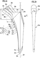
- FIG. 2a schematically illustrated contours of the prosthesis shafts 20a, 20b and 20c.
- Medial side surfaces 22a, 22b and 22c of the prosthetic stems 20a, 20b and 20c are concavely curved away from them and all have the identical radius of curvature.
- center points 26a, 26b and 26c of contact circles adjacent to the side surfaces 22a, 22b and 22c are offset relative to each other with respect to a longitudinal direction 28 defined by the prosthesis stems 20a, 20b and 20c by a distance 30 between the midpoints 26a and 26b and a distance 32 between the midpoints 26b and 26c.
- a total length of the prosthesis stem 20c is greater than a total length of the prosthetic stem 20b, which in turn is longer than a total length of the prosthesis stem 20a.
- Distal ends 34a, 34b and 34c of the prosthetic stems 20a, 20b and 20c are the further away from the respective end faces 24a, 24b and 24c the smaller the CCD angle 14a, 14b and 14c, respectively.
- Necks 36a, 36b, and 36c of the prosthetic stems 20a, 20b, and 20c define longitudinal neck axes 38a, 38b, and 38c that each subtend an angle with the longitudinal direction 28, the larger the smaller the CCD angle 14a, 14b, and 14c.
- the femoral bones 10a, 10b and 10c must be partially resected by separating the femoral heads 40a, 40b and 40c.
- a medullary canal of the femur bones 10a, 10b and 10c is then prepared with a medical instrumentation 42 comprising a rasp instrument 44.
- the rasp instrument 44 includes a rasp shaft 46 having a medial side surface 48 having a radius of curvature corresponding to the radius of curvature of the side surfaces 22a, 22b, and 22c of the prosthetic stems 20a, 20b, and 20c.
- a lateral side surface 50 of the rasp shaft 46 runs almost parallel to the longitudinal direction 28.
- the rasp shaft 46 In order for the same rasp shaft 46 to be used for the preparation of the femur bones 10a, 10b and 10c, it must be driven at different depths in preparation for the medullary canal of the respective femur bone 10a, 10b and 10c, the deeper the smaller the CCD angle 14a, 14b or 14c of the respective indication. In other words, the rasp shaft 46 must be driven deeper by the distance 32 for the implantation of the prosthesis shaft 20c for the indication Coxa vara in comparison to the indication Coxa norma. In contrast, the rasp stem 46 must be driven deeper by the distance 30 deeper into the femur bone 10b in the indication Coxa norma compared to the indication Coxa valga 12.
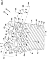
- the rasp shaft 46 is three Depth stops 52a, 52b and 52c formed.
- the depth stop 52a comprises two depth stop faces 54a
- the depth stop 52b comprises two depth stop faces 54b.
- the depth stop 52c includes a single depth stop surface 54c.
- rasp shaft 46 is mirror-symmetrical to a longitudinal plane 28 containing symmetry plane 56 is formed.
- the depth stop surfaces 54a, 54b and 54c define depth stop surface planes 58a, 58b and 58c that are parallel to each other.
- a distance between the depth stop surface plane 58a and 58b corresponds to the distance 30
- a distance between the depth stop surface plane 58b and 58c corresponds to the distance 32.
- the distance 30 corresponds to the distance 32.
- the depth stop surfaces 54a, 54b and 54c are formed equidistant from each other.
- the depth stop surfaces 54a, 54b and 54c form part of proximal end face portions 62a, 62b and 62c.
- a width of the depth stop surface 54c is greater than a width of the two depth stop surfaces 54a, which in turn are twice as wide as the depth stop surfaces 54b.
- the most proximal depth stop surface 54c corresponds to the indication Coxa vara 18, the depth stop surface 54b to the indication Coxa norma 16 and the depth stop surface 54a to the indication Coxa valga 12.
- a relative to the depth stop surfaces 54b medially inclined coupling end 64 of the rasp shaft 46 carries a symmetrical to the plane of symmetry formed coupling element 66 for coupling the rasp shaft 46 with a handle member, not shown in the figures.
- This can in particular have a striking surface in order to hit the rasp shaft 46 held by the grip element into the cavities of the femur bones 10a, 10b and 10c.
- the coupling element 66 has two against an inclined and in the medial direction facing side surfaces 68, which are connected to each other via a laterally facing cylindrical surface 70. In the area of the cylindrical surface, a recess 72 is formed in a lateral direction. A proximal end face 74 of the coupling element 66 lies below the depth stop surface plane 58c, ie completely distal thereof. A coupling element longitudinal axis 76 of the coupling element 66 is inclined relative to the depth stop surface planes 58a, 58b and 58c by an angle 78 which is smaller than 90 °. Preferably, it is in a range of 50 ° to 80 °. The coupling element longitudinal axis 76 is also located in the plane of symmetry 56.
- the rasp shaft 46 further includes two facing away side surfaces 80 connecting the side surfaces 48 and 50 together.
- the side surfaces 80 extend substantially parallel to one another and are mirror-symmetrical to the plane of symmetry 56.
- the two side surfaces 80 and the side surfaces 48 and 50 have a plurality of grooves 82 which are parallel to each other and have sharp edges 84 which form rasping teeth 86.
- the most distal depth stop surfaces 54a abut the side surfaces 80 and extend transversely thereto, preferably vertically.
- the side surface 50 extends in the proximal direction to substantially the height of the depth stop surface 54c. Furthermore, the depth stop surfaces 54b and 54a are each slightly offset in the medial direction with respect to the side surface 50.
- the depth stop surface 54c is formed on a substantially parallelepiped-shaped projection, which has an end face 88 pointing in the medial direction, which extends substantially parallel to the coupling element longitudinal axis 76.
- the end face 88 includes with the depth stop surface 54c an angle 90 which has a value in a range of about 50 ° to 70 °, preferably 60 °.
- the depth stop surfaces 54a extend farthest in the medial direction.
- the depth stop surface 54c protrudes in the medial direction over the depth stop surfaces 54b.
- the three depth stops 52a, 52b and 52c allow the rasp instrument 44 to be used in preparation for all the femoral bones 10a, 10b and 10c, regardless of whether the prosthesis stem 20a, 20b and 20c is to be implanted.
- the rasp shaft 46 is only hammered into the partially resected femur bone until the depth stop surface 54a, 54b and 54c assigned to the respective indication lies at the same height as a resection plane of the femur bones 10a, 10b and 10c.
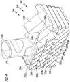
- FIG. 4 is a further embodiment of a generally designated by the reference numeral 144 rasp instrument partially shown. It agrees in its basic structure with the rasp instrument 44, so that identical elements are denoted by the same reference numerals, wherein the rasp instrument 144 is still preceded by the number "1".
- the rasp instrument 144 comprises a rasp shaft 146 which has a total of three depth stops 152a, 152b and 152c.
- the depth stops 152a and 152b are formed in the side surfaces 180 in the form of grooves 192a and 192b, extending transversely to the rasping teeth 186.
- the depth stop surfaces 154a, 154b and 154c define depth stop surface planes 158a, 158b and 158c that are parallel to each other.
- a distance 130 between the depth stop surface plane 158a and the depth stop surface plane 158b corresponds to the distance 132 between the depth stop surface plane 158b and the depth stop surface plane 158c.
- the two grooves 192a and 192b are spaced from both the end surface 196 and from each other.
- depth stop surface planes 158a, 158b and 158c extend transversely to the longitudinal direction 128 defined by the rasp shaft 146.
- the depth stop 152a corresponds to the indication Coxa valga and thus forms a corresponding insertion mark for a surgeon.
- the depth stop 152b corresponds to the indication Coxa norma and forms a corresponding insertion mark.
- the depth stop 152c defines an impact mark for the indication Coxa vara.
- rasp shaft 46 The areas of rasp shaft 146 designated rasp shaft 46 as depth stop surfaces 54a, 54b and 54c define shoulder height surfaces 198a, 198b and 198c.
- the shoulder height surface 198a corresponds to the shoulder height of the prosthesis shaft 120a
- the shoulder height surface 198b corresponds to the shoulder height of the prosthesis shaft 120b
- the shoulder height surface 198c corresponds to the shoulder height of the prosthesis shaft 120c.
- the depth stop surfaces 154a, 154b and 154c are colored differently. This is in FIG. 4 schematically represented by different hatchings.
- the depth abutment surfaces 154a, 154b and 154c may also be provided with different surface structures, which provide easy recognizability ensure respective depth stops 152a, 152b and 152c for a surgeon.
- identification elements 200a, 200b and 200c are designed in the form of protective caps 202a, 202b and 202c, which can be applied to the necks 136a, 136b and 136c of the prosthesis stems 120a, 120b and 120c or can be temporarily coupled thereto.
- the marking elements 200a, 200b and 200c are optionally colored in accordance with the indication of the respective prosthesis shaft 120a, 120b and 120c, with the same colors which serve to mark the depth stops 152a, 152b and 152c, thus for example blue for the indication Coxa vara, orange for the indication Coxa norma and green for the indication Coxa valga.
- an operator can select the shaft 120b corresponding to the indication Coxa norma and then knows immediately that he has to drive the rasp shaft 146 into the femur bone up to the depth stop 152b, whose depth stop surface 154b is colored with the same color as the marking element 200b for the implantation of the prosthesis stem 120b optimally prepare.
- the protective caps 202a, 202b and 202c may optionally have a coupling device, which enables a non-positive and / or positive connection with the necks 136a, 136b and 136c.
- the protective caps 202a, 202b and 202c protect the necks 136a, 136b and 136c from damage on the one hand and serve to identify the indication of the respective prosthesis stem 120a, 120b and 120c on the other hand.
- the protective caps 202a, 202b and 202c are removed and a condyle fit for the patient is placed on the necks 136a, 136b and 136c.
- an implantation set 204 is shown schematically comprising a total of three different implant parts in the form of prosthesis stems 120a ', 120b' and 120c '.
- the prosthetic stems 120a ', 120b' and 120c ' differ from the prosthetic stems 120a, 120b and 120c in that they include other marker elements 200a', 200b 'and 200c'.
- the indicia 200a ', 200b' and 200c ' are disposed on proximal facing planar end surfaces 204a', 204b 'and 204c' of the necks 136a ', 136b' and 136c '. They are in the form of geometric surface areas 206a ', 206b' and 206c ', each of which is circular.
- the surface areas 206a ', 206b' and 206c ' are in turn colored with the same colors as the depth stop surfaces 154a, 154b and 154c of the rasp shaft 146.
- the surgeon chooses the prosthesis stem 120a 'to treat the indication Coxa valga, he only has to drive the rasp stem 146 into the femur bone as far as the depth stop 152a.
- the three prosthesis stems 120a ', 120b' and 120c ' form a modular implant set 206 and, together with the rasp instrument 144, the implantation set 204.
Landscapes
- Health & Medical Sciences (AREA)
- Life Sciences & Earth Sciences (AREA)
- Surgery (AREA)
- Orthopedic Medicine & Surgery (AREA)
- Veterinary Medicine (AREA)
- General Health & Medical Sciences (AREA)
- Oral & Maxillofacial Surgery (AREA)
- Engineering & Computer Science (AREA)
- Biomedical Technology (AREA)
- Heart & Thoracic Surgery (AREA)
- Public Health (AREA)
- Animal Behavior & Ethology (AREA)
- Molecular Biology (AREA)
- Nuclear Medicine, Radiotherapy & Molecular Imaging (AREA)
- Medical Informatics (AREA)
- Transplantation (AREA)
- Cardiology (AREA)
- Vascular Medicine (AREA)
- Dentistry (AREA)
- Pathology (AREA)
- Prostheses (AREA)
- Physical Education & Sports Medicine (AREA)
Description
- Die vorliegende Erfindung betrifft ein medizinisches Instrumentarium, insbesondere zum Implantieren eines Hüftgelenkschafts, umfassend ein Raspelinstrument mit einem eine Längsrichtung definierenden Raspelschaft, wobei am Raspelschaft mindestens zwei Tiefenanschläge angeordnet oder ausgebildet sind, wobei mindestens zwei der mindestens zwei Tiefenanschläge mindestens eine Nut umfassen.
- Ferner umfasst die vorliegende Erfindung ein Implantationsset umfassend ein modulares Implantatset mit mindestens zwei unterschiedlichen Implantatteilen und ein medizinisches Instrumentarium, insbesondere zum Implantieren eines Hüftgelenkschafts, umfassend ein Raspelinstrument mit einem eine Längsrichtung definierenden Raspelschaft, wobei am Raspelschaft mindestens zwei Tiefenanschläge angeordnet oder ausgebildet sind, wobei jeder der mindestens zwei Tiefenanschläge mindestens eine Tiefenanschlagfläche umfasst.
- Künstliche Hüftgelenke, sogenannte Hüftgelenkendoprothesen, werden häufig bei Patienten eingesetzt, deren Hüftgelenke übermäßige Abnutzungserscheinungen zeigen. Andere Indikationen sind die sogenannte Coxa vara und die sogenannte Coxa valga. Bei der Coxa vara, der "auswärtsgebogene Hüfte", spricht man, wenn der sogenannte CCD-Winkel (Centrum-Collum-Diaphysen-Winkel), also der Winkel zwischen Oberschenkelhals und Schaft des Oberschenkelknochens, unter 120° liegt. Von einer "normalen Hüfte" spricht man, also von einer sogenannten Coxa norma, wenn der CCD-Winkel etwa 125° beträgt. Das Gegenteil einer Coxa vara ist die Coxa valga, die häufig bei Kleinkindern und Neugeborenen auftritt und eine Vergrößerung des CCD-Winkels auf mehr als 135° darstellt. Die Abweichungen von der Norm ergeben sich aufgrund von Wachstum - bei Neugeborenen sind Coxa valga-Situationen normal - und aufgrund pathologischer Änderungen. Beispielsweise bildet sich bei Senioren häufig eine Coxa vara aus. Aber auch aufgrund nationaler Unterschiede gibt es große Abweichungen in den Geometrien im proximalen Femurbereich.
- Für die endoprothetische Versorgung einer Hüfte sind besonders unterschiedliche mediale Konturen des Femurkanals, unterschiedliche Winkel des Schenkelhalses und damit verbunden auch die daraus resultierenden Positionen des Kopfmittelpunktes der Hüftgelenkendoprothesen von Bedeutung. Um diese drei oben beschriebenen Klassen, Coxa valga, Coxa norma und Coxa vara, entsprechend behandeln zu können, muss die sichere Fixierung des Implantates im Femurkanals sichergestellt werden. Dabei ist abhängig von der Art der Fixierung des Implantates im Femurkanal die mediale Anlage des Prothesenschafts an der Kortikalis des Femurs sehr wichtig. Daher ist ein Implantatsystem immer für eine der drei genannten Gruppen optimiert und kann zur Versorgung der anderen Gruppen nicht oder nur in Ausnahmefällen genutzt werden. Ferner ist bei den drei genannten Gruppen auch die Position des Rotationszentrums des Gelenks charakteristisch. Im Vergleich zu einem Standardfemur weist ein valgischer Femur eher ein kleines und ein varischer Femur einen eher großen Offset auf. Diese Bandbreite und vor allem das Zusammenspiel aus spezifischer medialer Anlage und Position des Kopfmittelpunkts sind mit den üblichen Systemen nicht abzudecken.
- Ein Problem ist, dass bei der Implantation der unterschiedlichen Hüftgelenkendoprothesen, die in Abhängigkeit der pathologischen Situation des Patienten implantiert werden, umfangreiche Instrumentarien benötigt werden.
- Aus der
US 5,019,108 ist ein modulares Implantat bekannt. Ein distales Fräswerkzeug zur Verwendung bei einem orthopädischen chirurgischen Eingriff zum Iimplantieren einer Revisionshüftgelenkendoprothese ist in derUS 2012/ 0259338 A1 beschrieben. Eine Reibahle für den Femur mit modularen Probekomponenten ist in derUS 5,766,216 offenbart. DieDE 298 16 064 U1 betrifft Raspeln zum Aushöhlen und Anpassen von Knochenhöhlen an hierin einzusetzende Hohlschaftprothesen. Ein chirurgisches Instrument zur Bearbeitung des Femurs ist aus derUS 2014/0276850 A1 bekannt. DieWO 96/17553 A1 EP 2 027 833 A1 ist eine prothetische Probehalskomponente beschrieben. - Daher ist es eine Aufgabe der vorliegenden Erfindung, die Implantation einer Hüftgelenkendoprothese und den Einsatz eines Implantationssets der eingangs beschriebenen Art zu vereinfachen.
- Diese Aufgabe wird bei einem medizinischen Instrumentarium der eingangs beschriebenen Art erfindungsgemäß dadurch gelöst, dass die Nuten am Raspelschaft parallel oder im Wesentlichen parallel zu einer in proximaler Richtung weisenden Endfläche des Raspelschafts verlaufen, dass das Instrumentarium ein am Raspelschaft angeordnetes oder ausgebildetes Kopplungselement zum Koppeln des Raspelschafts mit einem Griffelement umfasst, dass das Kopplungselement von der Endfläche in proximaler Richtung oder im Wesentlichen in proximaler Richtung weisend abstehend angeordnet oder ausgebildet ist und dass die durch die mindestens zwei Tiefenanschläge definierten Tiefenanschlagflächen unterschiedliche Oberflächenstrukturen aufweisen oder unterschiedlich eingefärbt sind.
- Ein derart ausgebildetes Instrumentarium ermöglicht es, mit nur einem Raspelinstrument Femurknochen von Patienten zur Implantation eines Hüftgelenksschafts vorzubereiten, die unterschiedliche pathologische Situationen an der Hüfte aufweisen. Zum Beispiel kann die Konstruktion der medialen Geometrie der Prothesenschäfte über einen Bogen erfolgen, der bei allen drei Varianten von Prothesenschäften zur Behandlung von Coxa vara, Coxa norma und Coxa valgus den gleichen Radius besitzt. Aufgrund der unterschiedlichen Höhen des Kreismittelpunktes des Schaftbogens wird jedoch, trotz gleichem Radius, eine unterschiedliche mediale Anlage erzeugt. Ist die übrige Geometrie des Prothesenschafts unterhalb einer Resektionslinie bei allen drei Varianten identisch, kann prinzipiell mit demselben Raspelinstrument das Implantatbett für alle drei Arten von Prothesenschäften präpariert werden. Voraussetzung ist lediglich, dass der Raspelschaft um den Wert, um den die Mittelpunkte der medialen Radien der Prothesenschäfte gegeneinander verschoben sind, tiefer oder nicht so tief in den Femurkanal eingeschlagen wird, beispielsweise 5 mm tiefer oder 5 mm weniger tief. Um sicher zu stellen, dass der Raspelschaft nur so tief eingeschlagen wird, dass der jeweils zu implantierende Prothesenschaft medialseitig optimal am Femur anliegt, sind mindestens zwei Tiefenanschläge am Raspelschaft angeordnet oder ausgebildet. Diese ermöglichen es beispielsweise, eine Einschlagtiefe zu begrenzen oder dem Operateur anzuzeigen, wie tief er den Raspelschaft bereits in den Femurkanal eingeschlagen hat. Das Vorsehen der mindestens zwei Tiefenschläge am Raspelschaft ermöglicht es insbesondere, mit nur einem einzigen Raspelinstrument mindestens zwei, vorzugsweise drei unterschiedliche Prothesenschäfte optimal zu implantieren. Vorteilhafterweise umfassen mindestens zwei der mindestens zwei Tiefenanschläge mindestens eine Nut. Beispielsweise können zwei Nuten und die Endfläche insgesamt drei Tiefenanschläge bilden. Zudem kann jeder Tiefenanschlag auch zwei oder mehr Nuten umfassen. Beispielsweise bei einem im Querschnitt rechteckigen Raspelschaft können pro Tiefenanschlag insgesamt bis zu vier Nuten auf vier Außenflächen ausgebildet werden, die zusammen insbesondere eine Ringnut bilden können und zusammen einen einzigen Tiefenanschlag definieren. Vorteilhaft ist es, dass die mindestens eine Nut am Raspelschaft parallel oder im Wesentlichen parallel zu einer in proximaler Richtung weisenden Endfläche des Raspelschafts verläuft. Beispielsweise dann, wenn die Endfläche selbst einen Tiefenanschlag definiert, können in der beschriebenen Weise Nuten parallel oder im Wesentlichen parallel zur Endfläche ausgebildet werden und so einem Operateur auf einfache Weise einen Abstand zur Endfläche anzeigen. Günstig ist es, dass die durch die mindestens zwei Tiefenanschläge definierten Tiefenanschlagflächen unterschiedliche Oberflächenstrukturen aufweisen oder unterschiedlich eingefärbt sind. Insbesondere ermöglichen Farben einem Operateur auf einfache Weise eine Unterscheidung der mindestens zwei Tiefenanschlagflächen. So kann er sicher erkennen, wie weit der Raspelschaft bereits in den Femurknochen eingetrieben ist und ob er gegebenenfalls noch weiter eingetrieben werden muss. Ferner ist es vorteilhaft, dass das Instrumentarium ein am Raspelschaft angeordnetes oder ausgebildetes Kopplungselement zum Koppeln des Raspelschafts mit einem Griffelement aufweist. Dies ermöglicht es, mit dem Griffelement, welches vorzugsweise eine Einschlagfläche zum Einschlagen des Raspelschafts in den Femur aufweist, den Raspelschaft einzuschlagen und dann den Raspelschaft und das Griffelement voneinander zu trennen, um beispielsweise einen Prothesenhals mit einem Gelenkkopf auf den Raspelschaft aufzusetzen, um Lage und Position des Gelenkkopfes zu bestimmen. Die ist günstig, um dann die optimale Prothesengröße sowie Halslänge und Gelenkkugeldurchmesser festzulegen. Auf besonders einfache Weise lässt sich das Griffelement mit dem Raspelschaft koppeln, wenn das Kopplungselement in proximaler Richtung oder im Wesentlichen in proximaler Richtung weisend angeordnet oder ausgebildet ist. Das Kopplungselement kann insbesondere in Form eines Kopplungsvorsprungs oder aber auch in Form einer Kopplungsaufnahme ausgebildet sein.
- Vorzugsweise umfasst eine in proximaler Richtung weisende Endfläche des Raspelschafts die mindestens eine Tiefenanschlagfläche. Von dieser können optional weitere Elemente abstehen, beispielsweise ein Kopplungselement zum Verbinden des Raspelschafts mit einem Handgriff oder dergleichen. Die Endfläche bildet somit einen Tiefenanschlag, welcher dem Operateur anzeigen kann, wie tief der Raspelschaft bereits in den Femurknochen eingetrieben ist.
- Günstig ist es, wenn die mindestens zwei Tiefenanschläge voneinander beabstandet angeordnet oder ausgebildet sind. So können unterschiedliche Einschlagtiefen vorgegeben oder dem Operateur angezeigt werden.
- Auf besonders einfache Weise ausbilden lässt sich das Instrumentarium, wenn mindestens einer der mindestens zwei Tiefenanschläge mindestens eine Nut umfasst. Beispielsweise kann eine Nut auf einfache Weise durch Fräsen oder andere spanende Bearbeitungsverfahren auf einer Außenseite des Raspelschafts ausgebildet werden.
- Vorteilhafterweise ist die mindestens eine Nut von der Endfläche beabstandet. So kann durch einen Abstand zwischen der Endfläche und der mindestens einen Nut für einen Operateur eine unterschiedliche Einschlagtiefe des Raspelschaft vorgegeben und angezeigt werden.
- Auf besonders einfache Weise ausbilden lässt sich das Instrumentarium, wenn die mindestens eine Nut eine Nutlängsrichtung definiert und/oder geradlinig oder im Wesentlichen geradlinig verläuft. Ferner erleichtert diese Ausgestaltung einem Operateur auch den Einsatz des Instrumentariums, da er insbesondere sicher eine Einschlagtiefe erkennen kann durch Vergleich einer Position der sichtbaren Nut und eines proximalen Endes des präparierten Femurknochens.
- Damit ein Operateur die mindestens zwei Tiefenanschläge auch während eines chirurgischen Eingriffs gut erkennen kann, ist es günstig, wenn die mindestens eine Nut auf einer Seitenfläche des Raspelschafts ausgebildet ist, welche in einer Richtung quer zur Längsrichtung weist.
- Gemäß einer weiteren bevorzugten Ausführungsform der Erfindung kann vorgesehen sein, dass die mindestens eine Nut mindestens eine Nutseitenfläche umfasst und dass die mindestens eine Nutseitenfläche die mindestens eine Tiefenanschlagfläche definiert. Beispielsweise kann eine Nut auch zwei, drei oder mehr Nutseitenflächen umfassen, je nach dem, welche Querschnittsform die Nut aufweist. Insbesondere kann die Nut keilförmig mit zwei Nutseitenflächen oder rechteckig mit drei Nutseitenflächen ausgebildet sein.
- Damit ein Operateur eine Einschlagtiefe eines Raspelschafts gut erkennen kann, ist es vorteilhaft, wenn die mindestens eine Nutseitenfläche parallel oder im Wesentlichen parallel zur Endfläche verläuft.
- Gemäß einer weiteren bevorzugten Ausführungsform der Erfindung kann vorgesehen sein, dass die mindestens zwei Tiefenanschläge jeweils mit einer individuellen Kennzeichnungsfarbe eingefärbt sind und dass die Kennzeichnungsfarbe entweder blau oder grün oder orange ist. Insbesondere können drei Tiefenanschläge jeweils mit einer der drei Farben eingefärbt sein, die eine eindeutige Unterscheidung der drei Tiefenanschläge ermöglichen. Insbesondere können auch die Tiefenanschlagflächen mit der Kennzeichnungsfarbe in der beschriebenen Weise eingefärbt sein.
- Günstigerweise sind drei Tiefenschläge vorgesehen. Drei Tiefenanschläge ermöglichen es, eine Implantation entsprechender Prothesenschäfte zur Behandlung von Patienten mit Coxa vara, Coxa norma und Coxa valga mit nur einem einzigen Raspelinstrument durchzuführen. Dies reduziert die Zahl der verfügbar zu haltenden Instrumente und damit Material- und Aufbereitungskosten.
- Die Handhabung des Instrumentariums wird weiter vereinfacht, wenn jeder der mindestens zwei Tiefenanschläge mindestens eine Tiefenanschlagfläche umfasst. Ein Tiefenanschlag kann eine, zwei oder mehr Tiefenanschlagflächen umfassen. Diese kennzeichnen vorzugweise dieselbe Einschlagtiefe für den Raspelschaft.
- Günstigerweise umfasst mindestens einer der mindestens zwei Tiefenanschläge zwei Tiefenanschlagflächen. Beispielsweise können die zwei Tiefenanschlagflächen derart angeordnet sein, dass sie auf unterschiedlichen Seiten des Raspelschafts angeordnet oder ausgebildet sind. So kann das Raspelinstrument zur Implantation von Hüftschäften sowohl für ein linkes als auch ein rechtes Hüftgelenks des Patienten einfach und sicher genutzt werden.
- Vorteilhaft ist es, wenn die zwei Tiefenanschlagflächen des mindestens einen der mindestens zwei Tiefenanschläge voneinander getrennt angeordnet oder ausgebildet sind. So sind sie beispielsweise gut erkennbar am Raspelschaft auf zwei unterschiedlichen, voneinander weg weisenden Seiten anordenbar oder ausbildbar.
- Die Herstellung des Instrumentariums vereinfacht sich insbesondere dadurch, dass die mindestens eine Tiefenanschlagfläche eben oder im Wesentlichen eben ist. Eine ebene Tiefenanschlagfläche ist für einen Operateur zudem besonders gut erkennbar, so dass er den Raspelschaft nur so tief wie erforderlich in den Femurknochen einschlagen kann.
- Um die Unterscheidbarkeit der mindestens zwei Tiefenanschläge für den Operateur zu verbessern, ist es vorteilhaft, wenn die Tiefenanschlagflächen der mindestens zwei Tiefenanschläge unterschiedlich breit sind.
- Vorteilhafterweise ist die proximalste Tiefenanschlagfläche am breitesten. So ist sie auch dann noch gut zu erkennen, wenn der Raspelschaft maximal tief in den Femurknochen eingeschlagen ist.
- Günstig ist es, wenn die distalste Tiefenanschlagfläche breiter ist als eine zwischen der distalsten und der proximalsten Tiefenanschlagfläche angeordnete oder ausgebildete mittlere Tiefenanschlagfläche. So sind die Tiefenanschläge, auch wenn sie relativ dicht beieinander liegen, deutlich zu unterscheiden.
- Um eine unterschiedliche Einschlagtiefe am Raspelschaft sicher zu markieren, ist es günstig, wenn die mindestens eine Tiefenanschlagfläche eines der mindestens zwei Tiefenanschläge von der mindestens einen Tiefenanschlagfläche eines anderen der mindestens zwei Tiefenanschläge bezogen auf die Längsrichtung beabstandet ist.
- Gemäß einer weiteren bevorzugten Ausführungsform der Erfindung kann vorgesehen sein, dass die mindestens eine Tiefenanschlagfläche eines der mindestens zwei Tiefenanschläge parallel oder im Wesentlichen parallel zu der mindestens einen Tiefenanschlagfläche eines anderen der mindestens zwei Tiefenanschläge verläuft. Parallel zueinander laufende Tiefenanschlagflächen sind als Tiefenanschläge für einen Operateur besonders gut erkennbar.
- Günstig ist es, wenn der Raspelschaft in proximaler Richtung weisende Endflächenbereiche aufweist, welche die Tiefenanschlagflächen bilden oder umfassen. Insbesondere können die Tiefenanschlagflächen in proximaler Richtung oder im Wesentlichen in proximaler Richtung weisend angeordnet oder ausgebildet sein. So sind sie für einen Operateur auch dann noch gut erkennbar, wenn der Raspelschaft in den Femurknochen eingeschlagen ist.
- Vorzugsweise umfasst der Raspelschaft drei, vier, fünf oder mehr Endflächenbereiche. Beispielsweise können zwei Endflächenbereiche jeweils eine Tiefenanschlagfläche umfassen, die gemeinsam einen Tiefenanschlag bilden.
- Besonders einfach wird die Herstellung des Raspelschafts, wenn mindestens zwei Tiefenanschlagflächen Tiefenanschlagflächenebenen definieren, welche quer, insbesondere senkrecht zur Längsrichtung verlaufen.
- Günstigerweise ist der Raspelschaft symmetrisch oder im Wesentlichen symmetrisch zu einer Symmetrieebene ausgebildet, welche quer, insbesondere senkrecht, zu mindestens einer der Tiefenanschlagflächen verläuft. Ferner kann die Symmetrieebene eine Längsachse des Raspelschafts enthalten. Diese Ausgestaltung vereinfacht den Aufbau des Raspelschafts. Zudem wird dessen Handhabbarkeit verbessert, da die Tiefenanschlagflächen sowohl bei der Vorbereitung eines linken Femurs als auch bei der Vorbereitung eines rechten Femurs gleich gut für den Operateur erkennbar sind.
- Günstigerweise umfasst der Raspelschaft drei Tiefenanschlagflächen, die äquidistant oder im Wesentlichen äquidistant bezogen auf die Längsrichtung angeordnet oder ausgebildet sind. Eine solche Ausgestaltung ist insbesondere dann günstig, wenn die Prothesenschäfte zur Behandlung von Coxa valga, Coxa norma und Coxa vara äquidistante mediale Krümmungsmittelpunkte aufweisen.
- Günstig ist es, wenn eine proximale Kopplungselementendfläche des Kopplungselements die am proximalsten verlaufende Tiefenanschlagflächenebene berührt oder distal derselben angeordnet ist. Diese Ausgestaltung ermöglicht es, dass nach Lösen des Griffelements insbesondere die proximalste Tiefenanschlagfläche dasjenige Element ist, das am weitesten in proximaler Richtung vom Raspelschaft absteht. Damit ist der Tiefenanschlag gut erkennbar, das Kopplungselement ist so am wenigsten störend angeordnet beziehungsweise ausgebildet.
- Gemäß einer weiteren bevorzugten Ausführungsform der Erfindung kann vorgesehen sein, dass eine Kopplungselementlängsachse des Kopplungselements und mindestens eine der Tiefenanschlagflächenebenen einen Winkel einschließen, welcher kleiner als 90° ist. Insbesondere liegt der Winkel in einem Bereich von 50° bis 80°. Den Winkel im angegeben Bereich zu wählen hat insbesondere den Vorteil, dass temporär ein Probehals mit einem Probegelenkkopf mit dem Kopplungselement verbunden werden kann, die dann in die gewünschte Richtung weisen.
- Der Aufbau des Instrumentariums vereinfacht sich weiter, wenn die Kopplungselemente Längsachse parallel zur Symmetrieebene verläuft oder in dieser liegt.
- Um die Herstellung des Instrumentariums weiter zu vereinfachen, ist es günstig, wenn der Raspelschaft zwei voneinander weg weisende Seitenflächen aufweist. Diese können insbesondere eben oder im Wesentlichen eben geformt sein. Des Weiteren können sie Schneidelemente tragen, beispielsweise Raspelzähne oder Raspelnuten, mit denen eine Kavität des Femurknochens bearbeitet werden kann.
- Vorteilhafterweise verlaufen die zwei Seitenflächen parallel oder im Wesentlichen parallel zur Symmetrieebene. So kann die Kavität des Femurknochens besonders kompakt präpariert werden zur Aufnahme des Prothesenschafts der Hüftgelen kendoprothese.
- Um die Einschlagtiefe des Raspelschafts für einen Operateur besonders gut erkennbar zu gestalten, ist es vorteilhaft, wenn eine der Tiefenanschlagflächen mindestens an eine der beiden Seitenflächen angrenzt. Vorzugsweise handelt es sich dabei um die distalste Tiefenanschlagfläche.
- Der distalste Tiefenanschlag ist für einen Operateur besonders gut erkennbar, wenn die distalste Tiefenanschlagflächenebene quer, insbesondere senkrecht, zu einer von einer der beiden Seitenflächen definierten Seitenflächenebene verläuft.
- Die Handhabbarkeit des medizinischen Instrumentariums lässt sich verbessern, wenn es ein Griffelement zum Koppeln mit dem Kopplungselement umfasst. Das Griffelement kann insbesondere an seinem proximalen Ende eine Einschlagfläche für ein Einschlagwerkzeug aufweisen, um den Raspelschaft in die Kavität des Femurknochens einzuschlagen.
- Ferner ist es vorteilhaft, wenn das Instrumentarium ein Einschlagwerkzeug aufweist. Mit diesem kann der Raspelschaft einfach und sicher in die Knochenkavität des Femurs eingeschlagen werden.
- Die eingangs gestellte Aufgabe wird ferner bei einem Implantationsset der eingangs beschriebenen Art erfindungsgemäß dadurch gelöst, dass die durch die mindestens zwei Tiefenanschläge definierten Tiefenanschlagflächen unterschiedliche Oberflächenstrukturen aufweisen oder unterschiedlich eingefärbt sind, dass die mindestens zwei unterschiedlichen Implantatteile jeweils ein Kennzeichnungselement umfassen, dass sich die Kennzeichnungselemente der mindestens zwei unterschiedlichen Implantatteile voneinander unterscheiden und dass jedem Kennzeichnungselement der mindestens zwei unterschiedlichen Implantatteile einer der mindestens zwei Tiefenanschläge zugeordnet ist.
- Mit dem erfindungsgemäß vorgeschlagenen Implantationsset ist es insbesondere möglich, mit nur einem Raspelinstrument eine Knochenkavität eines Femurknochens für die Implantation unterschiedlicher Implantatteile vorzubereiten, insbesondere für die Implantation unterschiedlicher Prothesenschäfte zur Behandlung unterschiedlicher Indikation. Die Handhabung des Instrumentariums wird weiter vereinfacht dadurch, dass jeder der mindestens zwei Tiefenanschläge mindestens eine Tiefenanschlagfläche umfasst. Ein Tiefenanschlag kann eine, zwei oder mehr Tiefenanschlagflächen umfassen. Diese kennzeichnen vorzugweise dieselbe Einschlagtiefe für den Raspelschaft. Günstig ist es, dass die durch die mindestens zwei Tiefenanschläge definierten Tiefenanschlagflächen unterschiedliche Oberflächenstrukturen aufweisen oder unterschiedlich eingefärbt sind. Insbesondere ermöglichen Farben einem Operateur auf einfache Weise eine Unterscheidung der mindestens zwei Tiefenanschlagflächen. So kann er sicher erkennen, wie weit der Raspelschaft bereits in den Femurknochen eingetrieben ist und ob er gegebenenfalls noch weiter eingetrieben werden muss. Ferner ist es günstig, dass die mindestens zwei unterschiedlichen Implantatteile jeweils ein Kennzeichnungselement umfassen und wenn sich die Kennzeichnungselemente der mindestens zwei unterschiedlichen Implantatteile voneinander unterscheiden. Die Kennzeichnungselemente erlauben es einem Operateur und seinem Hilfspersonal, sicher zwischen unterschiedlichen Implantatteilen, beispielsweise Prothesenschäften zur Behandlung von Coxa vara, Coxa norma und Coxa valgus, gezielt und richtig aus einem bereitgestellten Satz von Implantatteilen, die das Implantatset bilden, auszuwählen. Besonders sicher lassen sich vom Operateur ausgewählte Implantatteile implantieren, da jedem Kennzeichnungselement der mindestens zwei unterschiedlichen Implantatteile einer der mindestens zwei Tiefenanschläge zugeordnet ist. Wählt ein Operateur beispielsweise ein Implantatteil mit einem individuell ausgebildetem Kennzeichnungselement zur Implantation aus, dann weiß er sofort, welcher der mindestens zwei Tiefenanschläge am Raspelschaft zum ausgewählten Implantatteil korrespondiert und damit auch wie weit er den Raspelschaft in den Knochen einschlagen muss.
- Vorzugsweise unterscheiden sich die Kennzeichnungselemente der mindestens zwei unterschiedlichen Implantatteile farblich, aufgrund ihrer Oberflächenstruktur und/oder durch ihre Position am mindestens einen Implantatteil voneinander. So kann ein Operateur die unterschiedlichen Implantatteile auf einfache Weise unterscheiden, beispielsweise aufgrund ihrer jeweiligen farblichen Gestaltung oder ihrer Oberflächenstruktur oder in Abhängigkeit eines Ortes oder einer Position, an welcher sie am Implantatteil angeordnet oder ausgebildet sind.
- Besonders einfach und sicher lassen sich Implantatteile und Tiefenanschläge einander zuordnen, wenn eine Einfärbung der mindestens zwei Tiefenanschläge einer Einfärbung der Kennzeichnungselemente der mindestens zwei unterschiedlichen Implantatteile entspricht. Mit anderen Worten gehören gleiche Farben zusammen. Wird ein Implantatteil vom Operateur ausgewählt, kann er anhand der Farbe des Kennzeichnungselements sofort erkennen, welcher Tiefenanschlag am Raspelschaft zum ausgewählten Implantatteil korrespondiert. Damit weiß der Operateur auch, wie weit er den Raspelschaft in den Knochen eintreiben muss.
- Insbesondere ist es günstig, wenn die Kennzeichnungselemente der mindestens zwei unterschiedlichen Implantatteile mit denselben Kennzeichnungsfarben der Tiefenanschläge einfärbt sind. So lässt sich der bei der Vorbereitung der Femurkavität zu berücksichtigende Tiefenanschlag einfach und sicher bestimmen, wenn die Kennzeichnungsfarbe des Kennzeichnungselements vom ausgewählten Implantatteil bekannt ist.
- Auf besonders einfache Weise ausbilden lassen sich die Kennzeichnungselemente der mindestens zwei unterschiedlichen Implantatteile, wenn sie in Form geometrischer Flächenbereiche ausgebildet sind. Beispielsweise können auf einer äußeren Oberfläche des Implantatteils entsprechende geometrische Flächenbereiche farblich oder durch eine leicht erkennbare Oberflächenstruktur ausgebildet werden.
- Auf besonders einfache Weise ausbilden lassen sich die Kennzeichnungselemente, wenn die geometrischen Flächenbereiche in Form von Kreisflächen oder Vielecken ausgebildet sind. Diese lassen sich beispielsweise einstückig mit den Implantatteilen ausbilden oder in Form von Klebeetiketten aufbringen.
- Besonders gut und schnell erkennen kann ein Operateur die Art des von ihm ausgewählten Implantatteils, wenn die geometrischen Flächenbereiche an in proximaler Richtung weisenden Halsendflächen von Hälsen der Implantatteile angeordnet oder ausgebildet sind. Diese weisen auch nach der Implantation in seine Richtung, sodass er abschließend nochmals prüfen kann, ob das korrekte Implantatteil eingesetzt wurde.
- Vorteilhaft ist es, wenn die Kennzeichnungselemente mit den mindestens zwei unterschiedlichen Implantatteilen lösbar verbindbar ausgebildet oder unlösbar angeordnet oder ausbildet sind. Insbesondere lösbar verbindbare Kennzeichnungselemente haben den Vorteil, dass sie auf einfache Weise während oder nach dem chirurgischen Eingriff entfernt werden können. Beispielweise können sie zur Dokumentationszwecken aufbewahrt werden, um die Art des eingesetzten Implantatteils zu dokumentieren.
- Vorzugsweise sind die Kennzeichnungselemente in Form von Schutzkappen ausgebildet. Beispielsweise können diese ausgebildet sein, um auf Hälse von Implantatschäften aufgesteckt oder aufgeclipst zu werden. Sie dienen dann einem Operateur insbesondere zur Identifikation des Implantatteils und optional auch zum Schutz desselben. Insbesondere eine Beschädigung des Halses des Hüftgelenkschafts birgt die Gefahr, dass keine sichere Verbindung mit dem Kugelgelenkkopf mehr erreicht werden kann.
- Ferner ist es günstig, wenn die Kennzeichnungselemente mit den mindestens zwei unterschiedlichen Implantatteilen kraft- und/oder formschlüssig verbindbar sind. So kann insbesondere sichergestellt werden, dass sich die Kennzeichnungselemente nicht in unerwünschter Weise von den mit ihnen gekennzeichneten Implantatteilen lösen können.
- Die nachfolgende Beschreibung bevorzugter Ausführungsformen der Erfindung dient im Zusammenhang mit den Zeichnungen der näheren Erläuterung. Es zeigen:
- Figur 1a:
- eine schematische Darstellung einer Coxa valga;
- Figur 1b:
- eine schematische Darstellung einer Coxa norma;
- Figur 1c:
- eine schematische Darstellung einer Coxa vara;
- Figur 2a:
- eine schematische Darstellung übereinanderliegender Konturen dreier Hüftschäfte für die Indikationen Coxa valga, Coxa norma und Coxa vara;
- Figur 2b:
- eine Ansicht des Hüftschafts für die Indikation Coxa valga aus
Figur 2a in Richtung des Pfeils A; - Figur 3:
- eine schematische perspektivische Teilansicht eines nicht erfindungsgemäßen Raspelschafts mit drei Tiefenanschlägen;
- Figur 4:
- eine schematische perspektivische Teilansicht eines weiteren Ausführungsbeispiels eines Raspelschafts mit drei Tiefenanschlägen;
- Figur 5a:
- eine schematische Teilansicht eines Hüftschafts für die Indikation Coxa vara;
- Figur 5b:
- eine schematische Teilansicht eines Hüftschafts für die Indikation Coxa norma;
- Figur 5c:
- eine schematische Teilansicht eines Hüftschafts für die Indikation Coxa valga; und
- Figur 6:
- eine schematische Darstellung von Teilansichten weiterer Ausführungsbeispiele von Hüftschäften für die Indikationen Coxa valga, Coxa norma und Coxa vara mit dem in
Figur 4 teilweise dargestellten Raspelschaft. - In
Figur 1a ist ein Femurknochen 10a einer Coxa valga 12 schematisch dargestellt mit einem CCD-Winkel 14a, der größer als 140° ist. - In
Figur 1b ist ein Femurknochen 10b einer Coxa norma 16 schematisch dargestellt mit einem CCD-Winkel 14b von etwa 125°. - In
Figur 1c ist ein weiterer Femurknochen 10c einer Coxa vara 18 schematisch dargestellt mit einem CCD-Winkel 14c, der kleiner als 120° ist. - Zur Behandlung der drei in den
Figuren 1a bis 1c schematisch dargestellten pathologischen Situationen dienen die drei inFigur 2a schematisch dargestellten Konturen der Prothesenschäfte 20a, 20b und 20c. Mediale Seitenflächen 22a, 22b und 22c der Prothesenschäfte 20a, 20b und 20c sind von diesen weg weisend konkav gekrümmt und weisen alle den identischen Krümmungsradius auf. Werden proximale Endflächen 24 der Prothesenschäfte 20a, 20b und 20c bündig zueinander ausgerichtet, wie beispielhaft für deren Konturen inFigur 2a dargestellt, so hat dies zu Folge, dass Mittelpunkte 26a, 26b und 26c von an die Seitenflächen 22a, 22b und 22c anliegenden Berührkreisen bezogen auf eine durch die Prothesenschäfte 20a, 20b und 20c definierte Längsrichtung 28 relativ zueinander versetzt sind, und zwar um einen Abstand 30 zwischen den Mittelpunkten 26a und 26b und einem Abstand 32 zwischen den Mittelpunkten 26b und 26c. - Wie in
Figur 2a gut zu erkennen, ist eine Gesamtlänge des Prothesenschafts 20c größer als eine Gesamtlänge des Prothesenschafts 20b, welcher wiederum länger ist als eine Gesamtlänge des Prothesenschafts 20a. Distale Enden 34a, 34b und 34c der Prothesenschäfte 20a, 20b und 20c sind umso weiter von den jeweiligen Endflächen 24a, 24b und 24c entfernt, je kleiner der CCD-Winkel 14a, 14b beziehungsweise 14c ist. - Hälse 36a, 36b und 36c der Prothesenschäfte 20a, 20b und 20c definieren Halslängsachsen 38a, 38b und 38c, die mit der Längsrichtung 28 jeweils einen Winkel einschließen, welcher umso größer ist, je kleiner der CCD-Winkel 14a, 14b und 14c ist.
- Für die Implantation der Prothesenschäfte 20a, 20b und 20c müssen die Femurknochen 10a, 10b und 10c teilreseziert werden durch Abtrennen der Femurköpfe 40a, 40b und 40c. Ein Markkanal der Femurknochen 10a, 10b und 10c wird dann mit einem medizinischen Instrumentarium 42 umfassend ein Raspelinstrument 44 präpariert. Das Raspelinstrument 44 umfasst einen Raspelschaft 46 mit einer medialen Seitenfläche 48, die einen Krümmungsradius aufweist, welcher dem Krümmungsradius der Seitenflächen 22a, 22b und 22c der Prothesenschäfte 20a, 20b und 20c entspricht. Eine laterale Seitenfläche 50 des Raspelschafts 46 verläuft nahezu parallel zur Längsrichtung 28.
- Damit der gleiche Raspelschaft 46 zur Präparation der Femurknochen 10a, 10b und 10c genutzt werden kann, muss er zur Vorbereitung des Markraums des jeweiligen Femurknochen 10a, 10b 10c unterschiedlich tief eingeschlagen werden, und zwar umso tiefer je kleiner der CCD-Winkel 14a, 14b beziehungsweise 14c der jeweiligen Indikation ist. Mit anderen Worten muss der Raspelschaft 46 um den Abstand 32 tiefer eingeschlagen werden für die Implantation des Prothesenschafts 20c für die Indikation Coxa vara im Vergleich zur Indikation Coxa norma. Dagegen muss der Raspelschaft 46 um den Abstand 30 tiefer in den Femurknochen 10b tiefer eingeschlagen werdenbei der Indikation Coxa norma im Vergleich zur Indikation Coxa valga 12.
- Damit ein Operateur den Raspelschaft 46 entsprechend tief in den jeweiligen Femurknochen 10a, 10b und 10c einschlagen kann, sind am Raspelschaft drei Tiefenanschläge 52a, 52b und 52c ausgebildet. Der Tiefenanschlag 52a umfasst zwei Tiefenanschlagflächen 54a, der Tiefenanschlag 52b umfasst zwei Tiefenanschlagflächen 54b. Der Tiefenanschlag 52c umfasst eine einzige Tiefenanschlagfläche 54c. Insgesamt ist Raspelschaft 46 spiegelsymmetrisch zu einer die Längsrichtung 28 enthaltenden Symmetrieebene 56 ausgebildet.
- Die Tiefenanschlagflächen 54a, 54b und 54c definieren Tiefenanschlagflächenebenen 58a, 58b und 58c, die parallel zueinander verlaufen. Ein Abstand zwischen der Tiefenanschlagflächenebene 58a und 58b entspricht dem Abstand 30, ein Abstand zwischen der Tiefenanschlagflächenebene 58b und 58c entspricht dem Abstand 32. Bei den in den Figuren schematisch dargestellten Prothesenschäften 20a, 20b und 20c entspricht der Abstand 30 dem Abstand 32. Mit anderen Worten sind die Tiefenanschlagflächen 54a, 54b und 54c äquidistant zueinander ausgebildet.
- Die Tiefenanschlagflächen 54a, 54b und 54c bilden einen Teil von in proximaler Richtung weisenden Endflächenbereichen 62a, 62b und 62c. Eine Breite der Tiefenanschlagfläche 54c ist größer als eine Breite der beiden Tiefenanschlagflächen 54a, welche wiederum doppelt so breit sind wie die Tiefenanschlagflächen 54b.
- Die proximalste Tiefenanschlagfläche 54c korrespondiert zur Indikation Coxa vara 18, die Tiefenanschlagfläche 54b zur Indikation Coxa norma 16 und die Tiefenanschlagfläche 54a zur Indikation Coxa valga 12.
- Eine gegenüber den Tiefenanschlagflächen 54b nach medial geneigte Kopplungsendfläche 64 des Raspelschafts 46 trägt ein symmetrisch zur Symmetrieebene ausgebildetes Kopplungselement 66 zum Koppeln des Raspelschafts 46 mit einem in den Figuren nicht dargestellten Griffelement. Dieses kann insbesondere eine Einschlagfläche aufweisen, um den mit dem Griffelement gehaltenen Raspelschaft 46 in die Kavitäten der Femurknochen 10a, 10b und 10c einzuschlagen.
- Das Kopplungselement 66 weist zwei gegeneiner geneigte und in medialer Richtung weisende Seitenflächen 68 auf, welche über eine in lateraler Richtung weisende Zylinderfläche 70 miteinander verbunden sind. Im Bereich der Zylinderfläche ist in lateraler Richtung weisend eine Ausnehmung 72 ausgebildet. Eine in proximaler Richtung weisende Endfläche 74 des Kopplungselements 66 liegt unterhalb der Tiefenanschlagflächenebene 58c, also vollständig distal derselben. Eine Kopplungselementlängsachse 76 des Kopplungselements 66 ist gegenüber den Tiefenanschlagflächenebenen 58a, 58b und 58c um einen Winkel 78 geneigt, welcher kleiner ist als 90°. Vorzugweise liegt er in einem Bereich von 50° bis 80°. Die Kopplungselementlängsachse 76 liegt zudem in der Symmetrieebene 56.
- Der Raspelschaft 46 umfasst ferner zwei voneinander weg weisende Seitenflächen 80, die die Seitenflächen 48 und 50 miteinander verbinden. Die Seitenflächen 80 verlaufen im Wesentlichen parallel zueinander und sind spiegelsymmetrisch zur Symmetrieebene 56 ausgebildet. Die beiden Seitenflächen 80 sowie die Seitenflächen 48 und 50 weisen eine Vielzahl von Nuten 82 auf, die parallel zueinander verlaufen und scharfe Kanten 84 aufweisen, die Raspelzähne 86 bilden.
- Die distalsten Tiefenanschlagflächen 54a grenzen an die Seitenflächen 80 an und verlaufen quer zu diesen, vorzugsweise senkrecht.
- Die Seitenfläche 50 erstreckt sich in proximaler Richtung bis im Wesentlichen auf die Höhe der Tiefenanschlagfläche 54c. Ferner sind die Tiefenanschlagflächen 54b und 54a jeweils etwas in medialer Richtung bezogen auf die Seitenfläche 50 versetzt.
- Die Tiefenanschlagfläche 54c ist an einem im Wesentlichen quaderförmigen Vorsprung ausgebildet, welcher eine in medialer Richtung weisende Stirnfläche 88 aufweist, welche im Wesentlichen parallel zur Kopplungselementlängsachse 76 verläuft. Die Stirnfläche 88 schließt mit der Tiefenanschlagfläche 54c einen Winkel 90 ein, welcher einen Wert in einem Bereich von etwa 50° bis 70°, vorzugsweise 60°, aufweist. Somit erstrecken sich die Tiefenanschlagflächen 54a am weitesten in medialer Richtung. Ferner steht die Tiefenanschlagfläche 54c in medialer Richtung über die Tiefenanschlagflächen 54b vor.
- Die drei Tiefenanschläge 52a, 52b und 52c ermöglichen es, dass das Raspelinstrument 44 zur Vorbereitung für alle Femurknochen 10a, 10b und 10c genutzt werden kann, unabhängig davon, ob der Prothesenschaft 20a, 20b und 20c implantiert werden soll. Der Raspelschaft 46 wird abhängig von dem zu implantierenden Prothesenschaft 20a, 20b und 20c nur so weit in den teilweise resezierten Femurknochen eingeschlagen, bis die der jeweiligen Indikation zugeordnete Tiefenanschlagfläche 54a, 54b und 54c auf derselben Höhe liegt wie einen Resektionsebene der Femurknochen 10a, 10b und 10c. Durch das Vorsehen der Tiefenanschläge 52a, 52b und 52c am Raspelschaft 46 kann auf die Bereitstellung von zwei weiteren Raspelschäften für die beiden anderen Indikationen verzichtet werden.
- In
Figur 4 ist ein weiteres Ausführungsbeispiel eines insgesamt mit dem Bezugszeichen 144 bezeichneten Raspelinstruments teilweise dargestellt. Es stimmt in seinem grundsätzlichen Aufbau mit dem Raspelinstrument 44 überein, sodass identische Elemente mit denselben Bezugszeichen bezeichnet sind, wobei beim Raspelinstrument 144 jeweils noch die Ziffer "1" vorangestellt ist. - Das Raspelinstrument 144 umfasst einen Raspelschaft 146, welcher insgesamt drei Tiefenanschläge 152a, 152b und 152c aufweist. Die Tiefenanschläge 152a und 152b sind in Form von Nuten 192a und 192b in den Seitenflächen 180 ausgebildet, und zwar quer zu den Raspelzähnen 186 verlaufend. In proximaler Richtung, also in Richtung auf das Kopplungselement 166 hin weisende Nutseitenflächen 194a und 194b definieren Tiefenanschlagflächen 154a und 154b. Eine Endfläche 196 des Raspelschafts, von welchem sich das Kopplungselement 166 in proximaler Richtung weg erstreckt, definiert die Tiefenanschlagfläche 154c des Tiefenanschlags 152c.
- Die Tiefenanschlagflächen 154a, 154b und 154c definieren Tiefenanschlagflächenebenen 158a, 158b und 158c, die parallel zueinander verlaufen. Ein Abstand 130 zwischen der Tiefenanschlagflächenebene 158a und der Tiefenanschlagflächenebene 158b entspricht dem Abstand 132 zwischen der Tiefenanschlagflächenebene 158b und der Tiefenanschlagflächenebene 158c. Somit sind die beiden Nuten 192a und 192b sowohl von der Endfläche 196 als auch voneinander beabstandet.
- Ferner verlaufen die Tiefenanschlagflächenebenen 158a, 158b und 158c quer zur vom Raspelschaft 146 definierten Längsrichtung 128.
- Der Tiefenanschlag 152a korrespondiert zur Indikation Coxa valga und bildet somit eine entsprechende Einschlagmarkierung für einen Operateur.
- Der Tiefenanschlag 152b korrespondiert zur Indikation Coxa norma und bildet eine hierfür entsprechende Einschlagmarkierung.
- Ferner definiert der Tiefenanschlag 152c eine Einschlagmarkierung für die Indikation Coxa vara.
- Die beim Raspelschaft 46 als Tiefenanschlagflächen 54a, 54b und 54c bezeichneten Flächen des Raspelschafts 146 definieren Schulterhöhenflächen 198a, 198b und 198c. Die Schulterhöhenfläche 198a korrespondiert zur Schulterhöhe des Prothesenschafts 120a, die Schulterhöhenfläche 198b korrespondiert zur Schulterhöhe des Prothesenschafts 120b und die Schulterhöhenfläche 198c korrespondiert zur Schulterhöhe des Prothesenschafts 120c.
- Um die zum jeweiligen Tiefenanschlag 152a, 152b und 152c korrespondierende Indikation für einen Operateur leicht erkennbar zu machen, sind die Tiefenanschlagflächen 154a, 154b und 154c unterschiedlich eingefärbt. Dies ist in
Figur 4 schematisch durch unterschiedliche Schraffuren dargestellt. Optional können die Tiefenanschlagflächen 154a, 154b und 154c auch mit unterschiedlichen Oberflächenstrukturen versehen sein, die eine leichte Erkennbarkeit der jeweiligen Tiefenanschläge 152a, 152b und 152c für einen Operateur gewährleisten. - Um einem Operateur die Präparation eines Femurknochens zu erleichtern, sind optional, wie in den
Figuren 5a bis 5c beispielhaft dargestellt, Kennzeichnungselemente 200a, 200b und 200c in Form von Schutzkappen 202a, 202b und 202c ausgebildet, die auf die Hälse 136a, 136b und 136c der Prothesenschäfte 120a, 120b und 120c aufbringbar beziehungsweise temporär mit diesen koppelbar sind. - Die Kennzeichnungselemente 200a, 200b und 200c sind optional entsprechend der Indikation des jeweiligen Prothesenschafts 120a, 120b und 120c eingefärbt, und zwar mit denselben Farben, die zur Kennzeichnung der Tiefenanschläge 152a, 152b und 152c dienen, also beispielsweise blau für die Indikation Coxa vara, orange für die Indikation Coxa norma und grün für die Indikation Coxa valga. So kann beispielsweise ein Operateur den zur Indikation Coxa norma korrespondierenden Schaft 120b wählen und weiß dann sofort, dass er den Raspelschaft 146 bis zum Tiefenanschlag 152b, dessen Tiefenanschlagfläche 154b mit derselben Farbe wie das Kennzeichnungselement 200b eingefärbt ist, in den Femurknochen einschlagen muss, um diesen für die Implantation des Prothesenschafts 120b optimal zu präparieren.
- Die Schutzkappen 202a, 202b und 202c können optional eine Kopplungseinrichtung aufweisen, welche eine kraft- und/oder formschlüssige Verbindung mit den Hälsen 136a, 136b und 136c ermöglicht. Die Schutzkappen 202a, 202b und 202c schützen zum einen die Hälse 136a, 136b und 136c vor Beschädigungen und dienen zum anderen zur Kennzeichnung der Indikation des jeweiligen Prothesenschafts 120a, 120b und 120c.
- Nach dem Einsetzen der Prothesenschäfte 120a, 120b und 120c werden die Schutzkappen 202a, 202b und 202c entfernt und ein für den Patienten passender Gelenkkopf auf die Hälse 136a, 136b und 136c aufgesetzt.
- In
Figur 6 ist beispielhaft ein Implantationsset 204 schematisch dargestellt umfassend insgesamt drei unterschiedliche Implantatteile in Form von Prothesenschäften 120a', 120b' und 120c'. - Die Prothesenschäfte 120a', 120b' und 120c' unterscheiden sich von den Prothesenschäften 120a, 120b und 120c dadurch, dass sie andere Kennzeichnungselemente 200a', 200b' und 200c' umfassen. Die Kennzeichnungselemente 200a', 200b' und 200c' sind auf in proximaler Richtung weisenden ebenen Endflächen 204a', 204b' und 204c' der Hälse 136a', 136b' und 136c' angeordnet. Sie sind in Form geometrischer Flächenbereiche 206a', 206b' und 206c' ausgebildet, die jeweils kreisförmig sind.
- Die Flächenbereiche 206a', 206b' und 206c' sind wiederrum eingefärbt, und zwar mit denselben Farben wie die Tiefenanschlagflächen 154a, 154b und 154c des Raspelschafts 146.
- Wählt der Operateur beispielsweise den Prothesenschaft 120a' zur Behandlung der Indikation Coxa valga, so muss er den Raspelschaft 146 nur bis zum Tiefenanschlag 152a in den Femurknochen einschlagen.
- Die drei Prothesenschäfte 120a', 120b' und 120c' bilden ein modulares Implantatset 206 und zusammen mit dem Raspelinstrument 144 das Implantationsset 204.
-
- 10a, 10b, 10c
- Femurknochen
- 12
- Coxa valga
- 14a, 14b, 14c
- CCD-Winkel
- 16
- Coxa norma
- 18
- Coxa vara
- 20a, 20b, 20c
- Prothesenschaft
- 22a, 22b, 22c
- Seitenflächen
- 24
- Endflächen
- 26a, 26b, 26c
- Mittelpunkte
- 28
- Längsrichtung
- 30
- Abstand
- 32
- Abstand
- 34
- Ende
- 36a, 36b, 36c
- Hals
- 38
- Halslängsachse
- 40a, 40b, 40c
- Femurkopf
- 42
- Instrumentarium
- 44
- Raspelinstrument
- 46
- Raspelschaft
- 48
- Seitenflächen
- 50
- Seitenflächen
- 52a, 52b, 52c
- Tiefenanschlag
- 54a, 54b, 54c
- Tiefenanschlagfläche
- 56
- Symmetrieebene
- 58a, 58b, 58c
- Tiefenanschlagflächenebene
- 60a, 60b, 60c
- Breite
- 62a, 62b, 62c
- Endflächenbereiche
- 64
- Kopplungsendfläche
- 66
- Kopplungselement
- 68
- Seitenflächen
- 70
- Zylinderfläche
- 72
- Ausnehmung
- 74
- Endfläche
- 76
- Kopplungselementlängsachse
- 78
- Winkel
- 80
- Seitenflächen
- 82
- Nut
- 84
- Kante
- 86
- Raspelzahn
- 88
- Stirnfläche
- 90
- Winkel
- 120a, 120b, 120c
- Prothesenschaft
- 128
- Längsrichtung
- 130
- Abstand
- 132
- Abstand
- 136a, 136b, 136c
- Hals
- 142
- Instrumentarium
- 144
- Raspelinstrument
- 146
- Raspelschaft
- 152a, 152b, 152c
- Tiefenanschlag
- 154a, 154b, 154c
- Tiefenanschlagfläche
- 156
- Symmetrieebene
- 158a, 158b, 158c
- Tiefenanschlagflächenebene
- 166
- Kopplungselement
- 176
- Kopplungselementlängsachse
- 180
- Seitenfläche
- 186
- Raspelzahn
- 192a, 192b
- Nut
- 194a, 194b
- Nutseitenflächen
- 196
- Endfläche
- 198a, 198b, 198c
- Schulterhöhenflächen
- 200a, 200b, 200c
- Kennzeichnungselement
- 202a, 202b, 202c
- Schutzkappe
- 204
- Implantationsset
- 206
- Implantatset
- 120a', 120b', 120c'
- Prothesenschaft
- 200a', 200b', 200c'
- Kennzeichnungselement
- 204a', 204b', 204c'
- Endfläche
- 206a', 206b', 206c'
- Flächenbereich
Claims (15)
- Medizinisches Instrumentarium (42; 142), insbesondere zum Implantieren eines Hüftgelenkschafts (20a, 20b, 20c; 120a, 120b, 120c; 120a', 120b', 120c'), umfassend ein Raspelinstrument (44; 144) mit einem eine Längsrichtung (28; 128) definierenden Raspelschaft (46; 146), wobei am Raspelschaft (46; 146) mindestens zwei Tiefenanschläge (152a, 152b, 152c) angeordnet oder ausgebildet sind, wobei mindestens zwei der mindestens zwei Tiefenanschläge (152a, 152b) mindestens eine Nut (192a, 192b) umfassen, dadurch gekennzeichnet, dass die Nuten (192a, 192b) am Raspelschaft (146) parallel oder im Wesentlichen parallel zu einer in proximaler Richtung weisenden Endfläche (196) des Raspelschafts (146) verlaufen, dass das Instrumentarium ein am Raspelschaft (146) angeordnetes oder ausgebildetes Kopplungselement (166) zum Koppeln des Raspelschafts (146) mit einem Griffelement umfasst, dass das Kopplungselement (166) von der Endfläche (196) in proximaler Richtung oder im Wesentlichen in proximaler Richtung weisend abstehend angeordnet oder ausgebildet ist und dass die durch die mindestens zwei Tiefenanschläge (152a, 152b, 152c) definierten Tiefenanschlagflächen (154a, 154b, 154c) unterschiedliche Oberflächenstrukturen aufweisen oder unterschiedlich eingefärbt sind.
- Medizinisches Instrumentarium nach Anspruch 1, dadurch gekennzeichnet, dass jeder der mindestens zwei Tiefenanschläge (152a, 152b, 152c) mindestens eine Tiefenanschlagfläche (154a, 154b, 154c) umfasst.
- Medizinisches Instrumentarium nach Anspruch 2, dadurch gekennzeichnet, dass die in proximaler Richtung weisende Endfläche (196) des Raspelschafts (146) die mindestens eine Tiefenanschlagfläche (154c) umfasst.
- Medizinisches Instrumentarium nach einem der voranstehenden Ansprüche, dadurch gekennzeichnet, dass die mindestens zwei Tiefenanschläge (152a, 152b, 152c) voneinander beabstandet angeordnet oder ausgebildet sind.
- Medizinisches Instrumentarium nach einem der voranstehenden Ansprüche, dadurch gekennzeichnet, dass mindestens zwei der mindestens zwei Tiefenanschläge (152a, 152b) mindestens eine Nut (192a, 192b) umfassen.
- Medizinisches Instrumentarium nach einem der voranstehenden Ansprüche, dadurch gekennzeichnet, dassa) die mindestens eine Nut (192a, 192b) eine Nutlängsrichtung definiert und/oder geradlinig oder im Wesentlichen geradlinig verläuft
und/oderb) die mindestens eine Nut (192a, 192b) auf einer Seitenfläche (180) des Raspelschafts (146) ausgebildet ist, welche in einer Richtung quer zur Längsrichtung weist. - Medizinisches Instrumentarium nach Anspruch 2 oder einem der Ansprüche 3 bis 6, dadurch gekennzeichnet, dass die mindestens eine Nut (192a, 192b) mindestens eine Nutseitenfläche (194a, 194b) umfasst und dass die mindestens eine Nutseitenfläche (194a, 194b) die mindestens eine Tiefenanschlagfläche (154a, 154b) definiert.
- Medizinisches Instrumentarium nach Anspruch 2 oder einem der Ansprüche 3 bis 7, soweit diese direkt oder indirekt auf Anspruch 2 rückbezogen sind, dadurch gekennzeichnet, dass die mindestens eine Tiefenanschlagfläche (154a, 154b, 154c) eben ist.
- Medizinisches Instrumentarium nach Anspruch 2 oder einem der Ansprüche 3 bis 8, soweit diese direkt oder indirekt auf Anspruch 2 rückbezogen sind, dadurch gekennzeichnet, dass die mindestens eine Tiefenanschlagfläche (154a, 154b, 154c) eines der mindestens zwei Tiefenanschläge (152a, 152b, 152c) parallel oder im Wesentlichen parallel zu der mindestens einen Tiefenanschlagfläche (154a, 154b, 154c) eines anderen der mindestens zwei Tiefenanschläge (152a, 152b, 152c) verläuft.
- Medizinisches Instrumentarium nach Anspruch 2 oder einem der Ansprüche 3 bis 9, soweit diese direkt oder indirekt auf Anspruch 2 rückbezogen sind, dadurch gekennzeichnet, dass mindestens zwei Tiefenanschlagflächen (154a, 154b, 154c) Tiefenanschlagflächenebenen (158a, 158b, 158c) definieren, welche quer, insbesondere senkrecht, zur Längsrichtung (128) verlaufen.
- Medizinisches Instrumentarium nach einem der Ansprüche 2 bis 10, dadurch gekennzeichnet, dassa) der Raspelschaft (146) symmetrisch oder im Wesentlichen symmetrisch zu einer Symmetrieebene (56) ausgebildet ist, welche quer, insbesondere senkrecht, zu mindestens einer der Tiefenanschlagflächen (154a, 154b, 154c) verläuft,
und/oderb) dass drei Tiefenanschlagflächen (154a, 154b, 154c) vorgesehen sind, die äquidistant oder im Wesentlichen äquidistant bezogen auf die Längsrichtung (128) angeordnet oder ausgebildet sind. - Implantationsset (204) umfassend ein modulares Implantatset (206) mit mindestens zwei unterschiedlichen Implantatteilen (20a, 20b, 20c; 120a, 120b, 120c; 120a', 120b', 120c') und ein medizinisches Instrumentarium (42; 142), insbesondere zum Implantieren eines Hüftgelenkschafts (20a, 20b, 20c; 120a, 120b, 120c; 120a', 120b', 120c'), umfassend ein Raspelinstrument (144) mit einem eine Längsrichtung (128) definierenden Raspelschaft (146), wobei am Raspelschaft (146) mindestens zwei Tiefenanschläge (152a, 152b, 152c) angeordnet oder ausgebildet sind, wobei jeder der mindestens zwei Tiefenanschläge (152a, 152b, 152c) mindestens eine Tiefenanschlagfläche (154a, 154b, 154c) umfasst, dadurch gekennzeichnet, dass die durch die mindestens zwei Tiefenanschläge (152a, 152b, 152c) definierten Tiefenanschlagflächen (154a, 154b, 154c) unterschiedliche Oberflächenstrukturen aufweisen oder unterschiedlich eingefärbt sind, dass die mindestens zwei unterschiedlichen Implantatteile (120a, 120b, 120c; 120a', 120b', 120c') jeweils ein Kennzeichnungselement (200a, 200b, 200c; 200a', 200b', 200c') umfassen, dass sich die Kennzeichnungselemente (200a, 200b, 200c; 200a', 200b', 200c') der mindestens zwei unterschiedlichen Implantatteile (120a, 120b, 120c; 120a', 120b', 120c') voneinander unterscheiden und dass jedem Kennzeichnungselement (200a, 200b, 200c; 200a', 200b', 200c') der mindestens zwei unterschiedlichen Implantatteile (120a, 120b, 120c; 120a', 120b', 120c') einer der mindestens zwei Tiefenanschläge (154a, 154b, 154c) zugeordnet ist.
- Implantationsset nach Anspruch 13, dadurch gekennzeichnet, dass sich die Kennzeichnungselemente (200a, 200b, 200c; 200a', 200b', 200c') der mindestens zwei unterschiedlichen Implantatteile (120a, 120b, 120c; 120a', 120b', 120c') farblich, aufgrund ihrer Oberflächenstruktur und/ oder durch ihre Position am mindestens einen Implantatteil (120a, 120b, 120c; 120a', 120b', 120c') voneinander unterscheiden.
- Implantationsset nach Anspruch 13, dadurch gekennzeichnet, dass die Kennzeichnungselemente (200a', 200b', 200c') der mindestens zwei unterschiedlichen Implantatteile (120a', 120b', 120c') in Form geometrischer Flächenbereiche (206a', 206b', 206c') ausgebildet sind.
- Implantationsset nach Anspruch 13 oder 14, dadurch gekennzeichnet, dass die Kennzeichnungselemente (200a, 200b, 200c) mit den mindestens zwei unterschiedlichen Implantatteilen (120a, 120b, 120c) lösbar verbindbar ausgebildet oder unlösbar angeordnet oder ausgebildet sind.
Applications Claiming Priority (1)
| Application Number | Priority Date | Filing Date | Title |
|---|---|---|---|
| DE102014119083.1A DE102014119083A1 (de) | 2014-12-18 | 2014-12-18 | Medizinisches Instrumentarium und Implantationsset |
Publications (2)
| Publication Number | Publication Date |
|---|---|
| EP3047807A1 EP3047807A1 (de) | 2016-07-27 |
| EP3047807B1 true EP3047807B1 (de) | 2018-09-19 |
Family
ID=55070723
Family Applications (1)
| Application Number | Title | Priority Date | Filing Date |
|---|---|---|---|
| EP15201259.7A Active EP3047807B1 (de) | 2014-12-18 | 2015-12-18 | Medizinisches instrumentarium und implantationsset |
Country Status (4)
| Country | Link |
|---|---|
| US (1) | US9861374B2 (de) |
| EP (1) | EP3047807B1 (de) |
| JP (1) | JP6767744B2 (de) |
| DE (1) | DE102014119083A1 (de) |
Families Citing this family (9)
| Publication number | Priority date | Publication date | Assignee | Title |
|---|---|---|---|---|
| GB201120642D0 (en) | 2011-12-01 | 2012-01-11 | Depuy Int Ltd | Bone broach and method of manufacturing a bone broach |
| GB201705917D0 (en) | 2017-04-12 | 2017-05-24 | Davidson Craig | Femoral trialling kit and assembly |
| US11369492B2 (en) * | 2017-08-22 | 2022-06-28 | Depuy Ireland Unlimited Company | Trial neck |
| US20190099191A1 (en) * | 2017-09-29 | 2019-04-04 | DePuy Synthes Products, Inc. | Distally reaming broach |
| AU2019352742B2 (en) | 2018-10-04 | 2025-04-17 | Depuy Ireland Unlimited Company | Prosthesis extraction system |
| GB201905459D0 (en) | 2019-04-17 | 2019-05-29 | Depuy Ireland Ultd Co | Indexable femoral neck resection guide |
| USD1086459S1 (en) | 2021-11-23 | 2025-07-29 | Howmedica Osteonics Corp. | Femoral hip broach |
| CN114795383A (zh) * | 2022-05-11 | 2022-07-29 | 天衍医疗器材有限公司 | 一种膝关节翻修用打拔限位系统 |
| EP4501252A1 (de) * | 2023-08-01 | 2025-02-05 | Smith & Nephew, Inc. | Orthopädisches räumwerkzeug |
Family Cites Families (12)
| Publication number | Priority date | Publication date | Assignee | Title |
|---|---|---|---|---|
| US4671275A (en) * | 1985-11-14 | 1987-06-09 | Deyerle William M | Femoral shaft surgical rasp for use in hip prosthesis surgery |
| US5019108A (en) | 1990-02-02 | 1991-05-28 | Bertin Kim C | Modular implant |
| WO1996017553A1 (en) | 1994-12-05 | 1996-06-13 | Wright Medical Technology, Inc. | A modular humeral prosthesis, and modular instrumentation for preparing a humerus for same, and a method for implanting same |
| US5766261A (en) | 1996-02-01 | 1998-06-16 | Osteonics Corp. | Femoral revision broach with modular trial components and method |
| DE29816064U1 (de) | 1998-09-07 | 1998-11-05 | Forschungszentrum Karlsruhe GmbH, 76133 Karlsruhe | Raspel, insbesondere zum Aushöhlen und Anpassen von Knochenhöhlen an hierin einzusetzende Hohlschaftprothesen |
| US6224605B1 (en) * | 1999-11-24 | 2001-05-01 | Bristol-Myers Squibb Co. | Orthopaedic instrumentation assembly and method of using same |
| US6517581B2 (en) * | 2001-01-25 | 2003-02-11 | Zimmer, Inc. | Method and apparatus for preparing a femur to receive a modular prosthetic femoral component |
| GB0716403D0 (en) | 2007-08-22 | 2007-10-03 | Benoist Girard Sas | Trial prosthetic neck component |
| DE102008020199B4 (de) * | 2008-04-16 | 2018-08-30 | Aesculap Ag | Prothesenraspel |
| CA2758712A1 (en) * | 2009-04-15 | 2010-10-21 | Marc Reichen | Trial implant assembly |
| CN103813764B (zh) | 2011-04-06 | 2017-04-19 | 德普伊新特斯产品有限责任公司 | 植入修正髋关节假体的器械组件和使用它的整形外科手术 |
| US9113918B2 (en) | 2013-03-15 | 2015-08-25 | Depuy (Ireland) | Femoral surgical instrument and method of using same |
-
2014
- 2014-12-18 DE DE102014119083.1A patent/DE102014119083A1/de not_active Withdrawn
-
2015
- 2015-12-16 US US14/970,980 patent/US9861374B2/en active Active
- 2015-12-18 EP EP15201259.7A patent/EP3047807B1/de active Active
- 2015-12-18 JP JP2015247125A patent/JP6767744B2/ja active Active
Also Published As
| Publication number | Publication date |
|---|---|
| DE102014119083A1 (de) | 2016-06-23 |
| JP6767744B2 (ja) | 2020-10-14 |
| JP2016127913A (ja) | 2016-07-14 |
| EP3047807A1 (de) | 2016-07-27 |
| US9861374B2 (en) | 2018-01-09 |
| US20160175109A1 (en) | 2016-06-23 |
Similar Documents
| Publication | Publication Date | Title |
|---|---|---|
| EP3047807A1 (de) | Medizinisches instrumentarium und implantationsset | |
| DE602004008024T2 (de) | Geräte zum minimal-invasiven Fräsen von Knochen | |
| DE69415804T2 (de) | Flexible reibahle für einen markkanal | |
| DE69635564T2 (de) | Gerät zum Einsetzen von Rückenwirbelimplantaten | |
| DE69819567T2 (de) | Orthopädische Schnittführung und Hülse | |
| DE69433702T2 (de) | Schutzvorrichtung mit zwei Durchführungen zur Chirurgie des Zwischenwirbelraums | |
| DE69719006T2 (de) | Chirurgische Raspel zur Vorbereitung des Knochenkanals eines Femurs für künstliche Bildung des Hüftgelenks | |
| DE3688207T2 (de) | Chirurgische Instrumente. | |
| DE69100379T2 (de) | Vorrichtung zur Vorbereitung einer Prothese. | |
| DE69021171T2 (de) | Modulare Hüftgelenksprothese mit einstellbarer Positionierungseinheit. | |
| DE69919857T2 (de) | Wirbelkörper-Distraktor | |
| DE68925175T2 (de) | Protheseneinrichtung | |
| DE69105739T2 (de) | Modulares probesystem zum ersatz des hüftgelenks. | |
| DE69924574T2 (de) | Bauelemente und Werkzeuge zur intramedullären Revisionschirurgie der Tibia | |
| DE69720803T2 (de) | Raspel zum bearbeiten eines markkanals eines knochens | |
| DE3878156T2 (de) | Chirurgisches instrument. | |
| EP0069252B1 (de) | Gelenkendoprothese | |
| DE202011111061U1 (de) | Orthopädische Fräsvorrichtung zur Knochenpräparation, insbesondere Gelenkpräparation | |
| DE112013003358T5 (de) | System und Verfahren für Gelenkoberflächenersatz und -reparatur | |
| DE202021101423U1 (de) | Geführte Fräsvorrichtung für prothetische Chirurgie | |
| EP0359097B1 (de) | Hüftkopf-Schaft-Prothese | |
| EP3402418B1 (de) | Medizinisches raspelinstrument | |
| EP2964112B1 (de) | Medizinisches werkzeugsystem | |
| EP1627607B1 (de) | Implantatsystem | |
| DE10335388B4 (de) | Satz chirurgischer Referenzierungsvorrichtungen |
Legal Events
| Date | Code | Title | Description |
|---|---|---|---|
| PUAI | Public reference made under article 153(3) epc to a published international application that has entered the european phase |
Free format text: ORIGINAL CODE: 0009012 |
|
| AK | Designated contracting states |
Kind code of ref document: A1 Designated state(s): AL AT BE BG CH CY CZ DE DK EE ES FI FR GB GR HR HU IE IS IT LI LT LU LV MC MK MT NL NO PL PT RO RS SE SI SK SM TR |
|
| AX | Request for extension of the european patent |
Extension state: BA ME |
|
| 17P | Request for examination filed |
Effective date: 20170127 |
|
| RBV | Designated contracting states (corrected) |
Designated state(s): AL AT BE BG CH CY CZ DE DK EE ES FI FR GB GR HR HU IE IS IT LI LT LU LV MC MK MT NL NO PL PT RO RS SE SI SK SM TR |
|
| GRAP | Despatch of communication of intention to grant a patent |
Free format text: ORIGINAL CODE: EPIDOSNIGR1 |
|
| INTG | Intention to grant announced |
Effective date: 20180220 |
|
| GRAJ | Information related to disapproval of communication of intention to grant by the applicant or resumption of examination proceedings by the epo deleted |
Free format text: ORIGINAL CODE: EPIDOSDIGR1 |
|
| INTC | Intention to grant announced (deleted) | ||
| GRAP | Despatch of communication of intention to grant a patent |
Free format text: ORIGINAL CODE: EPIDOSNIGR1 |
|
| GRAS | Grant fee paid |
Free format text: ORIGINAL CODE: EPIDOSNIGR3 |
|
| INTG | Intention to grant announced |
Effective date: 20180720 |
|
| GRAA | (expected) grant |
Free format text: ORIGINAL CODE: 0009210 |
|
| AK | Designated contracting states |
Kind code of ref document: B1 Designated state(s): AL AT BE BG CH CY CZ DE DK EE ES FI FR GB GR HR HU IE IS IT LI LT LU LV MC MK MT NL NO PL PT RO RS SE SI SK SM TR |
|
| REG | Reference to a national code |
Ref country code: GB Ref legal event code: FG4D Free format text: NOT ENGLISH |
|
| REG | Reference to a national code |
Ref country code: CH Ref legal event code: EP Ref country code: CH Ref legal event code: NV Representative=s name: ISLER AND PEDRAZZINI AG, CH |
|
| REG | Reference to a national code |
Ref country code: AT Ref legal event code: REF Ref document number: 1042330 Country of ref document: AT Kind code of ref document: T Effective date: 20181015 |
|
| REG | Reference to a national code |
Ref country code: IE Ref legal event code: FG4D Free format text: LANGUAGE OF EP DOCUMENT: GERMAN |
|
| REG | Reference to a national code |
Ref country code: DE Ref legal event code: R096 Ref document number: 502015005961 Country of ref document: DE |
|
| REG | Reference to a national code |
Ref country code: NL Ref legal event code: MP Effective date: 20180919 |
|
| PG25 | Lapsed in a contracting state [announced via postgrant information from national office to epo] |
Ref country code: NO Free format text: LAPSE BECAUSE OF FAILURE TO SUBMIT A TRANSLATION OF THE DESCRIPTION OR TO PAY THE FEE WITHIN THE PRESCRIBED TIME-LIMIT Effective date: 20181219 Ref country code: BG Free format text: LAPSE BECAUSE OF FAILURE TO SUBMIT A TRANSLATION OF THE DESCRIPTION OR TO PAY THE FEE WITHIN THE PRESCRIBED TIME-LIMIT Effective date: 20181219 Ref country code: SE Free format text: LAPSE BECAUSE OF FAILURE TO SUBMIT A TRANSLATION OF THE DESCRIPTION OR TO PAY THE FEE WITHIN THE PRESCRIBED TIME-LIMIT Effective date: 20180919 Ref country code: FI Free format text: LAPSE BECAUSE OF FAILURE TO SUBMIT A TRANSLATION OF THE DESCRIPTION OR TO PAY THE FEE WITHIN THE PRESCRIBED TIME-LIMIT Effective date: 20180919 Ref country code: GR Free format text: LAPSE BECAUSE OF FAILURE TO SUBMIT A TRANSLATION OF THE DESCRIPTION OR TO PAY THE FEE WITHIN THE PRESCRIBED TIME-LIMIT Effective date: 20181220 Ref country code: LT Free format text: LAPSE BECAUSE OF FAILURE TO SUBMIT A TRANSLATION OF THE DESCRIPTION OR TO PAY THE FEE WITHIN THE PRESCRIBED TIME-LIMIT Effective date: 20180919 Ref country code: RS Free format text: LAPSE BECAUSE OF FAILURE TO SUBMIT A TRANSLATION OF THE DESCRIPTION OR TO PAY THE FEE WITHIN THE PRESCRIBED TIME-LIMIT Effective date: 20180919 |
|
| REG | Reference to a national code |
Ref country code: LT Ref legal event code: MG4D |
|
| PG25 | Lapsed in a contracting state [announced via postgrant information from national office to epo] |
Ref country code: AL Free format text: LAPSE BECAUSE OF FAILURE TO SUBMIT A TRANSLATION OF THE DESCRIPTION OR TO PAY THE FEE WITHIN THE PRESCRIBED TIME-LIMIT Effective date: 20180919 Ref country code: LV Free format text: LAPSE BECAUSE OF FAILURE TO SUBMIT A TRANSLATION OF THE DESCRIPTION OR TO PAY THE FEE WITHIN THE PRESCRIBED TIME-LIMIT Effective date: 20180919 Ref country code: HR Free format text: LAPSE BECAUSE OF FAILURE TO SUBMIT A TRANSLATION OF THE DESCRIPTION OR TO PAY THE FEE WITHIN THE PRESCRIBED TIME-LIMIT Effective date: 20180919 |
|
| PG25 | Lapsed in a contracting state [announced via postgrant information from national office to epo] |
Ref country code: EE Free format text: LAPSE BECAUSE OF FAILURE TO SUBMIT A TRANSLATION OF THE DESCRIPTION OR TO PAY THE FEE WITHIN THE PRESCRIBED TIME-LIMIT Effective date: 20180919 Ref country code: PL Free format text: LAPSE BECAUSE OF FAILURE TO SUBMIT A TRANSLATION OF THE DESCRIPTION OR TO PAY THE FEE WITHIN THE PRESCRIBED TIME-LIMIT Effective date: 20180919 Ref country code: NL Free format text: LAPSE BECAUSE OF FAILURE TO SUBMIT A TRANSLATION OF THE DESCRIPTION OR TO PAY THE FEE WITHIN THE PRESCRIBED TIME-LIMIT Effective date: 20180919 Ref country code: RO Free format text: LAPSE BECAUSE OF FAILURE TO SUBMIT A TRANSLATION OF THE DESCRIPTION OR TO PAY THE FEE WITHIN THE PRESCRIBED TIME-LIMIT Effective date: 20180919 Ref country code: CZ Free format text: LAPSE BECAUSE OF FAILURE TO SUBMIT A TRANSLATION OF THE DESCRIPTION OR TO PAY THE FEE WITHIN THE PRESCRIBED TIME-LIMIT Effective date: 20180919 Ref country code: ES Free format text: LAPSE BECAUSE OF FAILURE TO SUBMIT A TRANSLATION OF THE DESCRIPTION OR TO PAY THE FEE WITHIN THE PRESCRIBED TIME-LIMIT Effective date: 20180919 Ref country code: IS Free format text: LAPSE BECAUSE OF FAILURE TO SUBMIT A TRANSLATION OF THE DESCRIPTION OR TO PAY THE FEE WITHIN THE PRESCRIBED TIME-LIMIT Effective date: 20190119 |
|
| PG25 | Lapsed in a contracting state [announced via postgrant information from national office to epo] |
Ref country code: PT Free format text: LAPSE BECAUSE OF FAILURE TO SUBMIT A TRANSLATION OF THE DESCRIPTION OR TO PAY THE FEE WITHIN THE PRESCRIBED TIME-LIMIT Effective date: 20190119 Ref country code: SK Free format text: LAPSE BECAUSE OF FAILURE TO SUBMIT A TRANSLATION OF THE DESCRIPTION OR TO PAY THE FEE WITHIN THE PRESCRIBED TIME-LIMIT Effective date: 20180919 Ref country code: SM Free format text: LAPSE BECAUSE OF FAILURE TO SUBMIT A TRANSLATION OF THE DESCRIPTION OR TO PAY THE FEE WITHIN THE PRESCRIBED TIME-LIMIT Effective date: 20180919 |
|
| REG | Reference to a national code |
Ref country code: DE Ref legal event code: R097 Ref document number: 502015005961 Country of ref document: DE |
|
| PLBE | No opposition filed within time limit |
Free format text: ORIGINAL CODE: 0009261 |
|
| STAA | Information on the status of an ep patent application or granted ep patent |
Free format text: STATUS: NO OPPOSITION FILED WITHIN TIME LIMIT |
|
| PG25 | Lapsed in a contracting state [announced via postgrant information from national office to epo] |
Ref country code: DK Free format text: LAPSE BECAUSE OF FAILURE TO SUBMIT A TRANSLATION OF THE DESCRIPTION OR TO PAY THE FEE WITHIN THE PRESCRIBED TIME-LIMIT Effective date: 20180919 |
|
| 26N | No opposition filed |
Effective date: 20190620 |
|
| PG25 | Lapsed in a contracting state [announced via postgrant information from national office to epo] |
Ref country code: MC Free format text: LAPSE BECAUSE OF FAILURE TO SUBMIT A TRANSLATION OF THE DESCRIPTION OR TO PAY THE FEE WITHIN THE PRESCRIBED TIME-LIMIT Effective date: 20180919 Ref country code: LU Free format text: LAPSE BECAUSE OF NON-PAYMENT OF DUE FEES Effective date: 20181218 |
|
| REG | Reference to a national code |
Ref country code: IE Ref legal event code: MM4A |
|
| REG | Reference to a national code |
Ref country code: BE Ref legal event code: MM Effective date: 20181231 |
|
| PG25 | Lapsed in a contracting state [announced via postgrant information from national office to epo] |
Ref country code: IE Free format text: LAPSE BECAUSE OF NON-PAYMENT OF DUE FEES Effective date: 20181218 Ref country code: SI Free format text: LAPSE BECAUSE OF FAILURE TO SUBMIT A TRANSLATION OF THE DESCRIPTION OR TO PAY THE FEE WITHIN THE PRESCRIBED TIME-LIMIT Effective date: 20180919 |
|
| PG25 | Lapsed in a contracting state [announced via postgrant information from national office to epo] |
Ref country code: BE Free format text: LAPSE BECAUSE OF NON-PAYMENT OF DUE FEES Effective date: 20181231 |
|
| PG25 | Lapsed in a contracting state [announced via postgrant information from national office to epo] |
Ref country code: MT Free format text: LAPSE BECAUSE OF FAILURE TO SUBMIT A TRANSLATION OF THE DESCRIPTION OR TO PAY THE FEE WITHIN THE PRESCRIBED TIME-LIMIT Effective date: 20180919 |
|
| PG25 | Lapsed in a contracting state [announced via postgrant information from national office to epo] |
Ref country code: TR Free format text: LAPSE BECAUSE OF FAILURE TO SUBMIT A TRANSLATION OF THE DESCRIPTION OR TO PAY THE FEE WITHIN THE PRESCRIBED TIME-LIMIT Effective date: 20180919 |
|
| PG25 | Lapsed in a contracting state [announced via postgrant information from national office to epo] |
Ref country code: MK Free format text: LAPSE BECAUSE OF NON-PAYMENT OF DUE FEES Effective date: 20180919 Ref country code: CY Free format text: LAPSE BECAUSE OF FAILURE TO SUBMIT A TRANSLATION OF THE DESCRIPTION OR TO PAY THE FEE WITHIN THE PRESCRIBED TIME-LIMIT Effective date: 20180919 Ref country code: HU Free format text: LAPSE BECAUSE OF FAILURE TO SUBMIT A TRANSLATION OF THE DESCRIPTION OR TO PAY THE FEE WITHIN THE PRESCRIBED TIME-LIMIT; INVALID AB INITIO Effective date: 20151218 |
|
| REG | Reference to a national code |
Ref country code: AT Ref legal event code: MM01 Ref document number: 1042330 Country of ref document: AT Kind code of ref document: T Effective date: 20201218 |
|
| PG25 | Lapsed in a contracting state [announced via postgrant information from national office to epo] |
Ref country code: AT Free format text: LAPSE BECAUSE OF NON-PAYMENT OF DUE FEES Effective date: 20201218 |
|
| P01 | Opt-out of the competence of the unified patent court (upc) registered |
Effective date: 20230726 |
|
| REG | Reference to a national code |
Ref country code: CH Ref legal event code: U11 Free format text: ST27 STATUS EVENT CODE: U-0-0-U10-U11 (AS PROVIDED BY THE NATIONAL OFFICE) Effective date: 20260101 |
|
| PGFP | Annual fee paid to national office [announced via postgrant information from national office to epo] |
Ref country code: GB Payment date: 20251218 Year of fee payment: 11 |
|
| PGFP | Annual fee paid to national office [announced via postgrant information from national office to epo] |
Ref country code: FR Payment date: 20251217 Year of fee payment: 11 |
|
| PGFP | Annual fee paid to national office [announced via postgrant information from national office to epo] |
Ref country code: DE Payment date: 20251222 Year of fee payment: 11 |
|
| PGFP | Annual fee paid to national office [announced via postgrant information from national office to epo] |
Ref country code: IT Payment date: 20251231 Year of fee payment: 11 |
|
| PGFP | Annual fee paid to national office [announced via postgrant information from national office to epo] |
Ref country code: CH Payment date: 20260101 Year of fee payment: 11 |