EP3047199B1 - Lighting device with an optical element having a fluid passage - Google Patents
Lighting device with an optical element having a fluid passage Download PDFInfo
- Publication number
- EP3047199B1 EP3047199B1 EP14731638.4A EP14731638A EP3047199B1 EP 3047199 B1 EP3047199 B1 EP 3047199B1 EP 14731638 A EP14731638 A EP 14731638A EP 3047199 B1 EP3047199 B1 EP 3047199B1
- Authority
- EP
- European Patent Office
- Prior art keywords
- lighting device
- light
- optical element
- transmissive material
- passage
- Prior art date
- Legal status (The legal status is an assumption and is not a legal conclusion. Google has not performed a legal analysis and makes no representation as to the accuracy of the status listed.)
- Active
Links
- 230000003287 optical effect Effects 0.000 title claims description 83
- 239000012530 fluid Substances 0.000 title claims description 34
- 239000000463 material Substances 0.000 claims description 85
- 239000011148 porous material Substances 0.000 claims description 23
- 239000002245 particle Substances 0.000 claims description 11
- 238000001816 cooling Methods 0.000 claims description 8
- 230000017525 heat dissipation Effects 0.000 description 8
- 239000002096 quantum dot Substances 0.000 description 8
- OAICVXFJPJFONN-UHFFFAOYSA-N Phosphorus Chemical compound [P] OAICVXFJPJFONN-UHFFFAOYSA-N 0.000 description 4
- 230000005540 biological transmission Effects 0.000 description 4
- 238000006243 chemical reaction Methods 0.000 description 4
- 230000000694 effects Effects 0.000 description 4
- 238000005286 illumination Methods 0.000 description 4
- 238000010521 absorption reaction Methods 0.000 description 3
- 230000008901 benefit Effects 0.000 description 3
- 230000001902 propagating effect Effects 0.000 description 3
- 238000004804 winding Methods 0.000 description 3
- 229910019901 yttrium aluminum garnet Inorganic materials 0.000 description 3
- WUPHOULIZUERAE-UHFFFAOYSA-N 3-(oxolan-2-yl)propanoic acid Chemical compound OC(=O)CCC1CCCO1 WUPHOULIZUERAE-UHFFFAOYSA-N 0.000 description 2
- GWEVSGVZZGPLCZ-UHFFFAOYSA-N Titan oxide Chemical compound O=[Ti]=O GWEVSGVZZGPLCZ-UHFFFAOYSA-N 0.000 description 2
- 239000005083 Zinc sulfide Substances 0.000 description 2
- TZCXTZWJZNENPQ-UHFFFAOYSA-L barium sulfate Chemical compound [Ba+2].[O-]S([O-])(=O)=O TZCXTZWJZNENPQ-UHFFFAOYSA-L 0.000 description 2
- 229910052980 cadmium sulfide Inorganic materials 0.000 description 2
- 239000013078 crystal Substances 0.000 description 2
- 230000001419 dependent effect Effects 0.000 description 2
- 230000004313 glare Effects 0.000 description 2
- 230000020169 heat generation Effects 0.000 description 2
- 230000003993 interaction Effects 0.000 description 2
- 238000000034 method Methods 0.000 description 2
- 239000004033 plastic Substances 0.000 description 2
- 229920003023 plastic Polymers 0.000 description 2
- 230000008569 process Effects 0.000 description 2
- 239000007787 solid Substances 0.000 description 2
- 229910052984 zinc sulfide Inorganic materials 0.000 description 2
- 238000010146 3D printing Methods 0.000 description 1
- 229910003373 AgInS2 Inorganic materials 0.000 description 1
- 229910052684 Cerium Inorganic materials 0.000 description 1
- GPXJNWSHGFTCBW-UHFFFAOYSA-N Indium phosphide Chemical compound [In]#P GPXJNWSHGFTCBW-UHFFFAOYSA-N 0.000 description 1
- YNXRTZDUPOFFKZ-UHFFFAOYSA-N [In].[Ag]=S Chemical compound [In].[Ag]=S YNXRTZDUPOFFKZ-UHFFFAOYSA-N 0.000 description 1
- 230000004075 alteration Effects 0.000 description 1
- PNEYBMLMFCGWSK-UHFFFAOYSA-N aluminium oxide Inorganic materials [O-2].[O-2].[O-2].[Al+3].[Al+3] PNEYBMLMFCGWSK-UHFFFAOYSA-N 0.000 description 1
- 239000013590 bulk material Substances 0.000 description 1
- 229910052793 cadmium Inorganic materials 0.000 description 1
- BDOSMKKIYDKNTQ-UHFFFAOYSA-N cadmium atom Chemical compound [Cd] BDOSMKKIYDKNTQ-UHFFFAOYSA-N 0.000 description 1
- AQCDIIAORKRFCD-UHFFFAOYSA-N cadmium selenide Chemical compound [Cd]=[Se] AQCDIIAORKRFCD-UHFFFAOYSA-N 0.000 description 1
- 239000000919 ceramic Substances 0.000 description 1
- GWXLDORMOJMVQZ-UHFFFAOYSA-N cerium Chemical compound [Ce] GWXLDORMOJMVQZ-UHFFFAOYSA-N 0.000 description 1
- 239000003086 colorant Substances 0.000 description 1
- 230000000295 complement effect Effects 0.000 description 1
- LCUOIYYHNRBAFS-UHFFFAOYSA-N copper;sulfanylideneindium Chemical compound [Cu].[In]=S LCUOIYYHNRBAFS-UHFFFAOYSA-N 0.000 description 1
- 229910052593 corundum Inorganic materials 0.000 description 1
- 230000008878 coupling Effects 0.000 description 1
- 238000010168 coupling process Methods 0.000 description 1
- 238000005859 coupling reaction Methods 0.000 description 1
- 239000011521 glass Substances 0.000 description 1
- 229910052736 halogen Inorganic materials 0.000 description 1
- 150000002367 halogens Chemical class 0.000 description 1
- 238000004020 luminiscence type Methods 0.000 description 1
- 238000012986 modification Methods 0.000 description 1
- 230000004048 modification Effects 0.000 description 1
- 125000002080 perylenyl group Chemical group C1(=CC=C2C=CC=C3C4=CC=CC5=CC=CC(C1=C23)=C45)* 0.000 description 1
- 230000005855 radiation Effects 0.000 description 1
- 229920006395 saturated elastomer Polymers 0.000 description 1
- 239000004065 semiconductor Substances 0.000 description 1
- 239000000126 substance Substances 0.000 description 1
- 238000009423 ventilation Methods 0.000 description 1
- XLYOFNOQVPJJNP-UHFFFAOYSA-N water Substances O XLYOFNOQVPJJNP-UHFFFAOYSA-N 0.000 description 1
- 229910001845 yogo sapphire Inorganic materials 0.000 description 1
- DRDVZXDWVBGGMH-UHFFFAOYSA-N zinc;sulfide Chemical compound [S-2].[Zn+2] DRDVZXDWVBGGMH-UHFFFAOYSA-N 0.000 description 1
Images

Classifications
-
- F—MECHANICAL ENGINEERING; LIGHTING; HEATING; WEAPONS; BLASTING
- F21—LIGHTING
- F21V—FUNCTIONAL FEATURES OR DETAILS OF LIGHTING DEVICES OR SYSTEMS THEREOF; STRUCTURAL COMBINATIONS OF LIGHTING DEVICES WITH OTHER ARTICLES, NOT OTHERWISE PROVIDED FOR
- F21V3/00—Globes; Bowls; Cover glasses
- F21V3/04—Globes; Bowls; Cover glasses characterised by materials, surface treatments or coatings
- F21V3/06—Globes; Bowls; Cover glasses characterised by materials, surface treatments or coatings characterised by the material
- F21V3/08—Globes; Bowls; Cover glasses characterised by materials, surface treatments or coatings characterised by the material the material comprising photoluminescent substances
-
- F—MECHANICAL ENGINEERING; LIGHTING; HEATING; WEAPONS; BLASTING
- F21—LIGHTING
- F21K—NON-ELECTRIC LIGHT SOURCES USING LUMINESCENCE; LIGHT SOURCES USING ELECTROCHEMILUMINESCENCE; LIGHT SOURCES USING CHARGES OF COMBUSTIBLE MATERIAL; LIGHT SOURCES USING SEMICONDUCTOR DEVICES AS LIGHT-GENERATING ELEMENTS; LIGHT SOURCES NOT OTHERWISE PROVIDED FOR
- F21K99/00—Subject matter not provided for in other groups of this subclass
-
- F—MECHANICAL ENGINEERING; LIGHTING; HEATING; WEAPONS; BLASTING
- F21—LIGHTING
- F21K—NON-ELECTRIC LIGHT SOURCES USING LUMINESCENCE; LIGHT SOURCES USING ELECTROCHEMILUMINESCENCE; LIGHT SOURCES USING CHARGES OF COMBUSTIBLE MATERIAL; LIGHT SOURCES USING SEMICONDUCTOR DEVICES AS LIGHT-GENERATING ELEMENTS; LIGHT SOURCES NOT OTHERWISE PROVIDED FOR
- F21K9/00—Light sources using semiconductor devices as light-generating elements, e.g. using light-emitting diodes [LED] or lasers
- F21K9/20—Light sources comprising attachment means
- F21K9/23—Retrofit light sources for lighting devices with a single fitting for each light source, e.g. for substitution of incandescent lamps with bayonet or threaded fittings
- F21K9/232—Retrofit light sources for lighting devices with a single fitting for each light source, e.g. for substitution of incandescent lamps with bayonet or threaded fittings specially adapted for generating an essentially omnidirectional light distribution, e.g. with a glass bulb
-
- F—MECHANICAL ENGINEERING; LIGHTING; HEATING; WEAPONS; BLASTING
- F21—LIGHTING
- F21K—NON-ELECTRIC LIGHT SOURCES USING LUMINESCENCE; LIGHT SOURCES USING ELECTROCHEMILUMINESCENCE; LIGHT SOURCES USING CHARGES OF COMBUSTIBLE MATERIAL; LIGHT SOURCES USING SEMICONDUCTOR DEVICES AS LIGHT-GENERATING ELEMENTS; LIGHT SOURCES NOT OTHERWISE PROVIDED FOR
- F21K9/00—Light sources using semiconductor devices as light-generating elements, e.g. using light-emitting diodes [LED] or lasers
- F21K9/60—Optical arrangements integrated in the light source, e.g. for improving the colour rendering index or the light extraction
- F21K9/64—Optical arrangements integrated in the light source, e.g. for improving the colour rendering index or the light extraction using wavelength conversion means distinct or spaced from the light-generating element, e.g. a remote phosphor layer
-
- F—MECHANICAL ENGINEERING; LIGHTING; HEATING; WEAPONS; BLASTING
- F21—LIGHTING
- F21V—FUNCTIONAL FEATURES OR DETAILS OF LIGHTING DEVICES OR SYSTEMS THEREOF; STRUCTURAL COMBINATIONS OF LIGHTING DEVICES WITH OTHER ARTICLES, NOT OTHERWISE PROVIDED FOR
- F21V13/00—Producing particular characteristics or distribution of the light emitted by means of a combination of elements specified in two or more of main groups F21V1/00 - F21V11/00
- F21V13/02—Combinations of only two kinds of elements
- F21V13/08—Combinations of only two kinds of elements the elements being filters or photoluminescent elements and reflectors
-
- F—MECHANICAL ENGINEERING; LIGHTING; HEATING; WEAPONS; BLASTING
- F21—LIGHTING
- F21V—FUNCTIONAL FEATURES OR DETAILS OF LIGHTING DEVICES OR SYSTEMS THEREOF; STRUCTURAL COMBINATIONS OF LIGHTING DEVICES WITH OTHER ARTICLES, NOT OTHERWISE PROVIDED FOR
- F21V29/00—Protecting lighting devices from thermal damage; Cooling or heating arrangements specially adapted for lighting devices or systems
- F21V29/50—Cooling arrangements
- F21V29/502—Cooling arrangements characterised by the adaptation for cooling of specific components
- F21V29/506—Cooling arrangements characterised by the adaptation for cooling of specific components of globes, bowls or cover glasses
-
- F—MECHANICAL ENGINEERING; LIGHTING; HEATING; WEAPONS; BLASTING
- F21—LIGHTING
- F21V—FUNCTIONAL FEATURES OR DETAILS OF LIGHTING DEVICES OR SYSTEMS THEREOF; STRUCTURAL COMBINATIONS OF LIGHTING DEVICES WITH OTHER ARTICLES, NOT OTHERWISE PROVIDED FOR
- F21V29/00—Protecting lighting devices from thermal damage; Cooling or heating arrangements specially adapted for lighting devices or systems
- F21V29/50—Cooling arrangements
- F21V29/60—Cooling arrangements characterised by the use of a forced flow of gas, e.g. air
-
- F—MECHANICAL ENGINEERING; LIGHTING; HEATING; WEAPONS; BLASTING
- F21—LIGHTING
- F21V—FUNCTIONAL FEATURES OR DETAILS OF LIGHTING DEVICES OR SYSTEMS THEREOF; STRUCTURAL COMBINATIONS OF LIGHTING DEVICES WITH OTHER ARTICLES, NOT OTHERWISE PROVIDED FOR
- F21V29/00—Protecting lighting devices from thermal damage; Cooling or heating arrangements specially adapted for lighting devices or systems
- F21V29/50—Cooling arrangements
- F21V29/70—Cooling arrangements characterised by passive heat-dissipating elements, e.g. heat-sinks
- F21V29/83—Cooling arrangements characterised by passive heat-dissipating elements, e.g. heat-sinks the elements having apertures, ducts or channels, e.g. heat radiation holes
-
- F—MECHANICAL ENGINEERING; LIGHTING; HEATING; WEAPONS; BLASTING
- F21—LIGHTING
- F21V—FUNCTIONAL FEATURES OR DETAILS OF LIGHTING DEVICES OR SYSTEMS THEREOF; STRUCTURAL COMBINATIONS OF LIGHTING DEVICES WITH OTHER ARTICLES, NOT OTHERWISE PROVIDED FOR
- F21V3/00—Globes; Bowls; Cover glasses
- F21V3/04—Globes; Bowls; Cover glasses characterised by materials, surface treatments or coatings
- F21V3/06—Globes; Bowls; Cover glasses characterised by materials, surface treatments or coatings characterised by the material
-
- F—MECHANICAL ENGINEERING; LIGHTING; HEATING; WEAPONS; BLASTING
- F21—LIGHTING
- F21V—FUNCTIONAL FEATURES OR DETAILS OF LIGHTING DEVICES OR SYSTEMS THEREOF; STRUCTURAL COMBINATIONS OF LIGHTING DEVICES WITH OTHER ARTICLES, NOT OTHERWISE PROVIDED FOR
- F21V5/00—Refractors for light sources
- F21V5/10—Refractors for light sources comprising photoluminescent material
-
- F—MECHANICAL ENGINEERING; LIGHTING; HEATING; WEAPONS; BLASTING
- F21—LIGHTING
- F21V—FUNCTIONAL FEATURES OR DETAILS OF LIGHTING DEVICES OR SYSTEMS THEREOF; STRUCTURAL COMBINATIONS OF LIGHTING DEVICES WITH OTHER ARTICLES, NOT OTHERWISE PROVIDED FOR
- F21V7/00—Reflectors for light sources
- F21V7/22—Reflectors for light sources characterised by materials, surface treatments or coatings, e.g. dichroic reflectors
- F21V7/24—Reflectors for light sources characterised by materials, surface treatments or coatings, e.g. dichroic reflectors characterised by the material
- F21V7/26—Reflectors for light sources characterised by materials, surface treatments or coatings, e.g. dichroic reflectors characterised by the material the material comprising photoluminescent substances
-
- F—MECHANICAL ENGINEERING; LIGHTING; HEATING; WEAPONS; BLASTING
- F21—LIGHTING
- F21V—FUNCTIONAL FEATURES OR DETAILS OF LIGHTING DEVICES OR SYSTEMS THEREOF; STRUCTURAL COMBINATIONS OF LIGHTING DEVICES WITH OTHER ARTICLES, NOT OTHERWISE PROVIDED FOR
- F21V29/00—Protecting lighting devices from thermal damage; Cooling or heating arrangements specially adapted for lighting devices or systems
- F21V29/50—Cooling arrangements
- F21V29/70—Cooling arrangements characterised by passive heat-dissipating elements, e.g. heat-sinks
- F21V29/71—Cooling arrangements characterised by passive heat-dissipating elements, e.g. heat-sinks using a combination of separate elements interconnected by heat-conducting means, e.g. with heat pipes or thermally conductive bars between separate heat-sink elements
- F21V29/713—Cooling arrangements characterised by passive heat-dissipating elements, e.g. heat-sinks using a combination of separate elements interconnected by heat-conducting means, e.g. with heat pipes or thermally conductive bars between separate heat-sink elements in direct thermal and mechanical contact of each other to form a single system
-
- F—MECHANICAL ENGINEERING; LIGHTING; HEATING; WEAPONS; BLASTING
- F21—LIGHTING
- F21V—FUNCTIONAL FEATURES OR DETAILS OF LIGHTING DEVICES OR SYSTEMS THEREOF; STRUCTURAL COMBINATIONS OF LIGHTING DEVICES WITH OTHER ARTICLES, NOT OTHERWISE PROVIDED FOR
- F21V29/00—Protecting lighting devices from thermal damage; Cooling or heating arrangements specially adapted for lighting devices or systems
- F21V29/85—Protecting lighting devices from thermal damage; Cooling or heating arrangements specially adapted for lighting devices or systems characterised by the material
-
- F—MECHANICAL ENGINEERING; LIGHTING; HEATING; WEAPONS; BLASTING
- F21—LIGHTING
- F21V—FUNCTIONAL FEATURES OR DETAILS OF LIGHTING DEVICES OR SYSTEMS THEREOF; STRUCTURAL COMBINATIONS OF LIGHTING DEVICES WITH OTHER ARTICLES, NOT OTHERWISE PROVIDED FOR
- F21V3/00—Globes; Bowls; Cover glasses
- F21V3/02—Globes; Bowls; Cover glasses characterised by the shape
-
- F—MECHANICAL ENGINEERING; LIGHTING; HEATING; WEAPONS; BLASTING
- F21—LIGHTING
- F21Y—INDEXING SCHEME ASSOCIATED WITH SUBCLASSES F21K, F21L, F21S and F21V, RELATING TO THE FORM OR THE KIND OF THE LIGHT SOURCES OR OF THE COLOUR OF THE LIGHT EMITTED
- F21Y2115/00—Light-generating elements of semiconductor light sources
- F21Y2115/10—Light-emitting diodes [LED]
Definitions
- the present invention generally relates to heat management in lighting devices.
- Heat management is an important issue within the field of illumination and, in particular, within the field of solid state based illumination, such as illumination based on light emitting diodes, LEDs.
- illumination based on light emitting diodes, LEDs.
- heat generation is commonly an undesired effect since it can affect performance and life expectance of the light sources, as well as the choice of materials and the configuration of electronics for the lighting device.
- Heat may also be produced in optical elements of the lighting device, such as in wavelength-converting components by Stokes shift losses.
- lighting devices In order to reduce the effects of the heat generation, lighting devices normally comprise a heat sink arranged to dissipate heat from the light sources and other heat generating components, typically in the direction opposite to the main (or average) light propagation direction of the lighting device.
- CN202040621 shows a lighting device having holes extending in the heat sink to the surroundings for increasing the heat dissipation area to the surroundings and in the shade of the lighting device.
- US 2011/0298371 A1 discloses a LED light bulb with openings in a cover portion.
- US 3373275 A discloses a one piece molded light transmitting lens cover with masked ventilation openings.
- US 2011/0049749 A1 discloses a replaceable illumination module with a cover cap which includes micro-weave materials with pore sizes large enough for air transfer but too small to convey water droplets.
- US 3253675 A discloses an apparatus for absorbing acoustic energy comprising a light-transmitting member having one or more layers of a porous material which permits the transmission of light therethrough.
- EP 2461089 A1 discloses a lighting unit with a light transmissive lamp cap having a plurality of vent holes.
- US2011051423 A1 discloses an LED module. However, it would be desirable to achieve alternative solutions for improving heat dissipation from lighting devices.
- a lighting device comprises at least one light source, and at least one optical element.
- the at least one optical element is arranged to transmit light emitted by the light source.
- the at least one optical element is formed by placing two or more layers of a light transmissive material on top of each other, each of the two or more layers comprising at least one recess.
- the recesses are shaped and arranged such that, when the two or more layers are joined, a recess of one of the layers overlaps a recess of the other layer such that they together form a passage extending through the light transmissive material for allowing a flow of fluid through the optical element.
- the passage is arranged such that a major portion of the light emitted by the at least one light source entering the passage further propagates through the light transmissive material.
- the passage is cornered or curved and has a shape adapted such that an imaginary straight line between a first opening and a second opening of the passage crosses the light transmissive material.
- the present aspect is based on the realization that the heat management for a lighting device may be improved by arranging a passage (or hole) in the optical element in front of the light source.
- the passage allows transfer of heat generated by the light source by means of convection through the passage.
- the term "convection" may relate to transfer of heat by fluid movement.
- the fluid flowing through the passage may be the fluid present in the lighting device, which may be of a gaseous form, such as air.
- the passage may improve dissipation of heat generated in the optical element itself, such as by Stokes shift losses in wavelength-converting materials, which optionally may be arranged in the optical element.
- the heat generated in the optical element may be transferred through the passage by the fluid flow.
- Improved heat dissipation from the lighting device may e.g. enable higher operating intensities and/or longer lifetime of the lighting device.
- the optical element is utilized to facilitate heat dissipation from the lighting device.
- the optical element may be used as a complement to (or even instead of) a traditional heat sink, thereby enabling increased overall heat dissipation from the lighting device.
- the passage is arranged such that a major portion of the light emitted by the light source entering the passage further propagates through the light transmissive material, the passage has a limited influence on the light distribution of the lighting device. In other words, the passage is arranged such that a reduced amount of light is allowed to propagate directly through the passage without passing the light transmissive material.
- the passage is formed by the fluidly interconnected recesses.
- a space between the layers of light transmissive material may allow circulation of fluid between the layers, which may further improve heat convection.
- the circulation of fluid may be adjusted by adjusting the distance of the layers of light transmissive material, which influences the turbulence of the flow of fluid in the passage.
- the term "light transmissive material” is to be widely interpreted as any material or combination of materials (or substances) admitting at least some transmission of light.
- the light transmissive material may comprise transparent and/or translucent material (such as ceramics or plastics) and, optionally, particles (e.g. for scattering and/or wavelength conversion of light) embedded therein and/or applied thereto.
- any line of sight extending from the light source and through the passage crosses the light transmissive material, whereby the influence of the passage on the light distribution of the lighting device is further reduced.
- an increased amount of light from the light source entering the passage may interact with the light transmissive material at least once upon passing the optical element.
- the light source is not directly visible from outside of the optical element through the passage, whereby glare from the light source is reduced.
- At least two of the layers of light transmissive material may be arranged such that light transmissive material of one of the two layers laterally overlaps the recess in the other one of the two layers, whereby a major portion of the light entering one of the through-holes further propagates through at least one of the other layers of light transmissive material.
- light entering one of the recesses may interact at least once with the light transmissive material in one of the layers upon passing (or propagating through) the optical element.
- the passage is cornered or curved and has a shape adapted such that an imaginary straight line between a first opening and a second opening of the passage (such as between two opposite openings of the passage) crosses the light transmissive material.
- an imaginary straight line between a first opening and a second opening of the passage such as between two opposite openings of the passage
- the position of the optical element relative to the light source may be less critical with regard to reducing the amount of light entering the passage without further propagating through the light transmissive material, as the non-straight shape of the passage may (at least partially) inhibit light from passing the passage without also passing the light transmissive material.
- the optical element may be provided with a plurality of passages, whereby the convection of heat is further improved. Further, the area of the optical element exposed to the flow of fluid increases, which improves dissipation of heat from the optical element into the passages.
- the optical element may comprise a porous material comprising pores extending through the light transmissive material, whereby the pores form the passages for flow of fluid through the optical element.
- the pores may e.g. extend between two opposite surfaces of optical element.
- the extension of the pores through the optical element may be winding (or at least non-straight), whereby light emitted by the light source entering a pore further propagates through the light transmissive material surrounding the pore.
- the winding pores increase the area of the light transmissive material exposed to the flowing fluid, whereby dissipation and convection of heat is improved.
- the porous light transmissive material comprises multiple refractive index shifts at the interfaces between the light transmissive material and the voids (typically comprising the fluid) formed by the pores, whereby the optical element may be used as a diffuser of the lighting device. Multiple refractive index shifts may provide scattering of light propagating through the porous material.
- the transmissive material may preferably have a higher refractive index compared to that of the fluid (e.g. air).
- the volume of the pores may make up at least 30% of the total volume of the optical element, which increases the convection and dissipation of heat from the optical element.
- the at least one optical element may be any one of a wavelength converting element, a diffuser element, and a combination of a diffuser and a wavelength converting element.
- the optical element may be arranged to adjust properties of light emitted by the light source.
- the optical element may for example be arranged to scatter light emitted by the light source in order to provide a more uniform light distribution (often perceived as softer light) of the lighting device.
- Heat producing processes may occur in the light transmissive material, in particular if the light transmissive material comprises wavelength converting material (e.g.
- the passage providing a flow of fluid, and thereby heat convection, through the optical element may facilitate dissipation of heat generated by such processes in the optical element.
- the light transmissive material may comprise particles for scattering (e.g. TiO 2 , BaSO 4 and/or Al 2 O 3 particles) and/or converting a wavelength of light emitted by the light source.
- the particles in the light transmissive material may be reflective (e.g. opaque, such as white) for scattering light.
- the particles may be wavelength converting particles having an atomic (or molecular) structure having an energy gap corresponding to the energy of the light emitted by the light source. Generally, whenever light is absorbed and re-emitted by the particles, the wavelength of the light is increased. Most of the energy loss defined by the difference in energy prior to the absorption and after the re-emission is emitted as heat radiation. The heat convection through the optical element may facilitate dissipation of the heat resulting from such a wavelength conversion.
- the optical element may be positioned at a distance from the at least one light source being larger than 2 cm, such as larger than 3 cm or 5 cm. Such a distance allows the fluid to circulate more freely between the optical element and the light source, which facilitates transfer of fluid out through the passage, whereby an increased amount of fluid can pass through the passage per time unit.
- the at least one optical element may be positioned at a distance from the at least one light source being closer than 3 mm, such as closer than 2 mm, 1 mm or 0.5 mm, which provides a reduced size of (more compact) lighting device.
- a ratio of the thickness of the light transmissive material to the average diameter of the passage is at least 2, such as at least 4 or 6.
- An increased ratio between the thickness of the optical element (or at least of the light transmissive material surrounding the passage) and the width of the passage reduces the amount of light passing through the passage without interacting with the light transmissive material.
- the lighting device may further comprise active cooling means arranged to produce a flow of fluid through the at least one passage, preferably in direction away from the light source.
- the active cooling means may enhance the flow of fluid produced by the heat convection effect, thereby improving the heat dissipation from the lighting device.
- the active cooling means may e.g. comprise a fan.
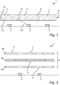
- Figure 1 is a cross-section of the lighting device 1.
- the lighting device 1 comprises one or more light sources 3, such as solid state based light sources (e.g. light emitting diodes, LEDs), and an optical element 5 arranged to transmit light emitted by the light sources 3.
- the optical element 5 comprises light transmissive material 7 and one or more (in the present example two) passages, or in this case through-holes, 9 extending through the light transmissive material 7 from a first surface 13 to a second surface 15 of the optical element 5.
- the passages 9 extend between opposite sides of the optical element 5.
- the passages 9 are arranged to allow a flow of fluid through the optical element 5, such as out of a space defined between the light sources 3 and the optical element 5.
- the fluid flowing through the passages 9 may be the fluid present in the lighting device 1, such as any gaseous fluid and preferably air.
- Fluid surrounding the optical element 5 circulates in and out of the passages 9 of the optical element 5, thereby providing heat convection.
- the flow of fluid removes heat present in the space between the light sources 3 and the optical element 5, which facilitates heat dissipation from the lighting device 1.
- the configuration of the passages 9 and the positioning of the light sources 3 relative to the passages 9 is adapted such that a major portion (preferably substantially all) light 16 emitted by the light sources 3 entering the passages 9 further propagates through the light transmissive material 7.
- a majority of the light emitted by the light sources 3 passing through the passages 9 interacts at least once with the light transmissive material 7.
- the passages 9 are configured such that any line of sight extending from each light source 3 and crosses a passage 9 at any point also crosses the light transmissive material 7.
- the light sources 3 are not directly visible through the passages 9 when looking at the first surface 13 of the optical element 5.
- the amount of light, which enters the passages 3 and subsequently interacts with the light transmissive material 7 is determined by the shape of the passages 9, the dimensions of the passages 9 relative to the surrounding light transmissive material 7 and the position of the passages 9 relative to the light sources 3.
- the aspect ratio of the thickness of the light transmissive material 7 to the average diameter of the passages 9 is at least 2, such as at least 4 or 6.
- the light transmissive material 7 may be significantly thicker than the width of the passages 9.
- positioning of the light sources 3 with respect to the passages 9 may be adapted to the angle of spread of the light sources 3.
- the passages 9 of the optical element 5 may be (substantially) straight through-holes arranged in a sheet of light transmissive material 7.
- the passages 9 may e.g. have a substantially cylindrical shape with any convenient cross-section, such as a circular, polygon, elliptic, hyperbolic or parabolic shape.
- a lighting device 1 having one or more through holes or passages will be described with reference to Figure 2 .
- the lighting device may be similarly configured as the lighting device described with reference to Figure 1 , except that the optical element 5 comprises a plurality of layers 18 of light transmissive material 7 and each layer 18 has at least one through-hole 11.
- the passages for allowing the flow of fluid through the optical element 5 are in this embodiment formed by the fluidly interconnected through-holes 11 and the spaces defined between the layers 18.
- the total volume of the layers 18 may be rather small compared to the total volume of the passages (i.e. the through-holes 11 and the space between the layers 18) for facilitating circulation of fluid in the passages and thereby improving the heat convection through the optical element 5.
- the distances between the different layers 18 may be equal to each other or vary.
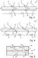
- a lighting device 1 having through holes or passages will be described with reference to Figures 3 and 4 .
- the lighting device may be similarly configured as the lighting device described with reference to Figure 1 , except that the passages 9 are shaped such that an imaginary straight line between a first opening 17 and a second opening 19 of the passage 9 crosses the light transmissive material 7 of the optical element 5, whereby heat transportation through the passages 9 may be effected without causing glare from the light sources 3.
- the passages 9 may be cornered, as illustrated in Figure 3 , or curved as illustrated in Figure 4 .
- the passages 9 of the lighting device shown in Figure 4 may e.g.
- the first curve 21 and the second curve 23 may be interconnected by a part of the passage 9 that is substantially horizontal or slightly tilted.
- the passages 9 may have any non-straight shape allowing light emitted by the light sources entering the passages to further propagate through the light transmissive material 7.
- the optical element 5 comprising the curved or cornered passages 9 may be formed by placing two or more layers 26, 28 of light transmissive material on top of each other, wherein each layer comprises at least one recess 30, as illustrated in Figure 5 .
- the two layers 26, 28 are spaced apart.
- the optical element 5 may comprise two spaced apart layers split at a plane where the corner of the passages is formed.
- the recesses 30 are shaped and arranged such that, when the layers 26, 28 are joined, a recess 30 of one 26 of the layers overlaps a recess of the other 28 layer such that they together form a passage 9 extending through the optical element 5.
- the curved and/or cornered passages 9 may be formed by means of 3D printing of the optical element 5.
- a lighting device 1 having one or more through holes or passages will be described with reference to Figure 6 .
- the lighting device may be similarly configured as the lighting device described with reference to Figure 1 , or as described with reference to Figure 2 comprising two or more optical elements, except that the optical element 5 comprises a porous material with a plurality of pores 25 extending through the light transmissive material 7 between the first surface 13 and the second surface 15.
- the pores 25 form the passages in the optical element 5 for allowing a flow of fluid through the optical element 5.
- the pores 25 may have a relatively narrow diameter and random winding shape, whereby light emitted by the light sources entering a pore 25 further propagates through the light transmissive material 7.
- the volume of the pores may make up at least 30% of the total volume of the optical element 5 for facilitating heat convention.
- the lighting device 1 may e.g. be a retrofit LED-based lighting device, as illustrated in Figure 7 .
- the lighting device may be any type of lighting arrangement and is not limited to LED-lamps or luminaires.
- the lighting device may e.g. be implemented in a lamp, luminaire, light engine or a system comprising several lighting devices.
- the lighting device 1 may be used in one or more of the following applications: shop lighting systems, home lighting systems, accent lighting systems, spot lighting systems, theatre lighting systems, decorative lighting systems, lighting systems, automotive lighting applications, projection systems, display systems, warning sign systems, medical lighting application systems, indicator sign systems, and household application systems.
- the lighting device 1 may optionally comprise an enclosure (or envelope) 27, which together with the heat sink 29 (or lower portion of the lighting device) encloses the optical element 5 and the light source 3.
- the enclosure 27 may have the shape of a bulb.
- the lighting device 1 may further comprise a socket 31 for coupling the lighting device 1 to a lamp fixture.
- the optical element 5 may be arranged in front of the light source 3, e.g. to cover or enclose the light source 3.
- the optical element 5 may have a sphere-like (or dome-like) shape.
- An inner volume between the optical element 5 and the light source 3 is fluidly connected to an outer volume between by the enclosure 27 and the optical element 5 via the passages 9.
- the passages 9 are arranged to enable a flow of air between the inner volume and the outer volume of the lighting device 1 to transport the heat produced from the light sources 3 and the optical element 5 to the outer volume.
- the lighting device 1 may further comprise active cooling means (not shown) arranged to produce a flow of fluid through the passages 9, preferably in direction away from the light source 3.
- the active cooling means may be configured to produce a flow of fluid in the heat conduction direction, i.e. from the inner volume to the outer volume in the lighting device 1.
- the active cooling means may enhance the flow of fluid produced by the heat convection effect.
- the active cooling means may e.g. comprise a fan.
- the light transmissive material 7 may comprise a transparent or translucent bulk material, such as glass or plastics.
- the light transmissive material 7 may further include scattering particles for scattering light emitted by the light source 3.
- the optical element 5 may comprise particles causing an exothermic reaction when illuminated such that heat is produced. Heat generated in the light transmissive material 7 may be dissipated partly via the heat convection in the passages.
- the light transmissive material 7 in the optical element 5 may comprise wavelength converting material, such as a phosphor. Particles of the wavelength converting material absorb and re-emit light through fluorescence, phosphorescence, luminescence, chemiluminscence or a combination thereof.
- suitable wavelength converting materials are organic luminescent materials based on perylene derivatives.
- the organic luminescent material may be transparent and non-scattering.
- the wavelength converting material may comprise quantum dots or quantum rods.
- Quantum dots are small crystals of semiconducting material generally having a width or diameter of only a few nanometers. When excited by incident light, a quantum dot emits light of a color determined by the size and material of the crystal. Light of a particular color can therefore be produced by adapting the size of the dots.
- Most known quantum dots with emission in the visible range are based on cadmium selenide (CdSe) with shell such as cadmium sulfide (CdS) and zinc sulfide (ZnS).
- Cadmium free quantum dots such as indium phosphide (InP), and copper indium sulfide (CuInS 2 ) and/or silver indium sulfide (AgInS 2 ) can also be used. Quantum dots show very narrow emission band and, thus, they show saturated colors. Furthermore, the emission color can be tuned by adapting the size of the quantum dots. Any type of quantum dot may be used in the light transmissive material 7.
- the light transmissive material 7 may comprise an inorganic phosphor.
- inorganic phosphor materials include, but are not limited to, cerium (Ce) doped YAG (Y 3 Al 5 O 12 ) or LuAG (Lu 3 Al 5 O 12 ). Ce doped YAG emits yellowish light, whereas Ce doped LuAG emits yellow-greenish light.
- Examples of other inorganic phosphors materials which emit red light may include, but are not limited to ECAS and BSSN; ECAS being Ca (1-x) AlSiN 3 :Eu x wherein 0 ⁇ x ⁇ 1, preferably 0 ⁇ x ⁇ 0.2; and BSSN being Ba (2-x-z) M x Si (5-y) Al y N (8-y) O y :Eu z wherein M represents Sr or Ca, 0 ⁇ x ⁇ 1, 0 ⁇ y ⁇ 4, 0.0005 ⁇ z ⁇ 0.05, and preferably 0 ⁇ x ⁇ 0.2).
- ECAS being Ca (1-x) AlSiN 3 :Eu x wherein 0 ⁇ x ⁇ 1, preferably 0 ⁇ x ⁇ 0.2
- BSSN being Ba (2-x-z) M x Si (5-y) Al y N (8-y) O y :Eu z wherein M represents Sr or Ca, 0 ⁇ x ⁇ 1, 0 ⁇ y ⁇ 4, 0.0005 ⁇ z ⁇ 0.05, and preferably 0 ⁇ x ⁇
Landscapes
- Engineering & Computer Science (AREA)
- General Engineering & Computer Science (AREA)
- Physics & Mathematics (AREA)
- Microelectronics & Electronic Packaging (AREA)
- Optics & Photonics (AREA)
- Non-Portable Lighting Devices Or Systems Thereof (AREA)
- Arrangement Of Elements, Cooling, Sealing, Or The Like Of Lighting Devices (AREA)
Description
- The present invention generally relates to heat management in lighting devices.
- Heat management is an important issue within the field of illumination and, in particular, within the field of solid state based illumination, such as illumination based on light emitting diodes, LEDs. Generally, when light is emitted by a light source, heat is generated. The heat generation is commonly an undesired effect since it can affect performance and life expectance of the light sources, as well as the choice of materials and the configuration of electronics for the lighting device. Heat may also be produced in optical elements of the lighting device, such as in wavelength-converting components by Stokes shift losses.
- In order to reduce the effects of the heat generation, lighting devices normally comprise a heat sink arranged to dissipate heat from the light sources and other heat generating components, typically in the direction opposite to the main (or average) light propagation direction of the lighting device.
CN202040621 shows a lighting device having holes extending in the heat sink to the surroundings for increasing the heat dissipation area to the surroundings and in the shade of the lighting device. -
US 2011/0298371 A1 discloses a LED light bulb with openings in a cover portion.US 3373275 A discloses a one piece molded light transmitting lens cover with masked ventilation openings.US 2011/0049749 A1 discloses a replaceable illumination module with a cover cap which includes micro-weave materials with pore sizes large enough for air transfer but too small to convey water droplets.US 3253675 A discloses an apparatus for absorbing acoustic energy comprising a light-transmitting member having one or more layers of a porous material which permits the transmission of light therethrough.EP 2461089 A1 discloses a lighting unit with a light transmissive lamp cap having a plurality of vent holes.US2011051423 A1 discloses an LED module. However, it would be desirable to achieve alternative solutions for improving heat dissipation from lighting devices. - It would be advantageous to achieve a lighting device overcoming, or at least alleviating, the above mentioned drawbacks. It would be desirable to enable an alternative lighting device with improved heat management.
- To better address one or more of these concerns, a lighting device having the features defined in the independent claim is provided. Preferable embodiments are defined in the dependent claims.
- According to an aspect, a lighting device is provided. The lighting device comprises at least one light source, and at least one optical element. The at least one optical element is arranged to transmit light emitted by the light source. The at least one optical element is formed by placing two or more layers of a light transmissive material on top of each other, each of the two or more layers comprising at least one recess. The recesses are shaped and arranged such that, when the two or more layers are joined, a recess of one of the layers overlaps a recess of the other layer such that they together form a passage extending through the light transmissive material for allowing a flow of fluid through the optical element. Further, the passage is arranged such that a major portion of the light emitted by the at least one light source entering the passage further propagates through the light transmissive material. The passage is cornered or curved and has a shape adapted such that an imaginary straight line between a first opening and a second opening of the passage crosses the light transmissive material.
- The present aspect is based on the realization that the heat management for a lighting device may be improved by arranging a passage (or hole) in the optical element in front of the light source. The passage allows transfer of heat generated by the light source by means of convection through the passage. In the present specification, the term "convection" may relate to transfer of heat by fluid movement. The fluid flowing through the passage may be the fluid present in the lighting device, which may be of a gaseous form, such as air. Further, the passage may improve dissipation of heat generated in the optical element itself, such as by Stokes shift losses in wavelength-converting materials, which optionally may be arranged in the optical element. The heat generated in the optical element may be transferred through the passage by the fluid flow. Improved heat dissipation from the lighting device may e.g. enable higher operating intensities and/or longer lifetime of the lighting device. With the present aspect, the optical element is utilized to facilitate heat dissipation from the lighting device. The optical element may be used as a complement to (or even instead of) a traditional heat sink, thereby enabling increased overall heat dissipation from the lighting device. Further, as the passage is arranged such that a major portion of the light emitted by the light source entering the passage further propagates through the light transmissive material, the passage has a limited influence on the light distribution of the lighting device. In other words, the passage is arranged such that a reduced amount of light is allowed to propagate directly through the passage without passing the light transmissive material. Hence, most of the light entering the passage interacts with the light transmissive material upon transmission through the optical element. Interaction with the light transmissive material should be understood as any type of interaction such as transmission, reflection, scattering, absorption and/or re-emission of light. Thus, the passage is formed by the fluidly interconnected recesses. A space between the layers of light transmissive material may allow circulation of fluid between the layers, which may further improve heat convection. The circulation of fluid may be adjusted by adjusting the distance of the layers of light transmissive material, which influences the turbulence of the flow of fluid in the passage.
- In the present specification, the term "light transmissive material" is to be widely interpreted as any material or combination of materials (or substances) admitting at least some transmission of light. For example, the light transmissive material may comprise transparent and/or translucent material (such as ceramics or plastics) and, optionally, particles (e.g. for scattering and/or wavelength conversion of light) embedded therein and/or applied thereto.
- According to an embodiment, any line of sight extending from the light source and through the passage crosses the light transmissive material, whereby the influence of the passage on the light distribution of the lighting device is further reduced. With the present embodiment, an increased amount of light from the light source entering the passage may interact with the light transmissive material at least once upon passing the optical element. As there is no line of sight, which extends from the light source through the passage without passing the light transmissive material, the light source is not directly visible from outside of the optical element through the passage, whereby glare from the light source is reduced.
- At least two of the layers of light transmissive material may be arranged such that light transmissive material of one of the two layers laterally overlaps the recess in the other one of the two layers, whereby a major portion of the light entering one of the through-holes further propagates through at least one of the other layers of light transmissive material. Thus, light entering one of the recesses may interact at least once with the light transmissive material in one of the layers upon passing (or propagating through) the optical element.
- The passage is cornered or curved and has a shape adapted such that an imaginary straight line between a first opening and a second opening of the passage (such as between two opposite openings of the passage) crosses the light transmissive material. As light naturally propagates in a straight direction, light entering the passage will pass the light transmissive material if the passage is cornered or curved. The position of the optical element relative to the light source may be less critical with regard to reducing the amount of light entering the passage without further propagating through the light transmissive material, as the non-straight shape of the passage may (at least partially) inhibit light from passing the passage without also passing the light transmissive material.
- According to an embodiment, the optical element may be provided with a plurality of passages, whereby the convection of heat is further improved. Further, the area of the optical element exposed to the flow of fluid increases, which improves dissipation of heat from the optical element into the passages.
- According to an embodiment, the optical element may comprise a porous material comprising pores extending through the light transmissive material, whereby the pores form the passages for flow of fluid through the optical element. The pores may e.g. extend between two opposite surfaces of optical element. The extension of the pores through the optical element may be winding (or at least non-straight), whereby light emitted by the light source entering a pore further propagates through the light transmissive material surrounding the pore. Furthermore, the winding pores increase the area of the light transmissive material exposed to the flowing fluid, whereby dissipation and convection of heat is improved. Further, the porous light transmissive material comprises multiple refractive index shifts at the interfaces between the light transmissive material and the voids (typically comprising the fluid) formed by the pores, whereby the optical element may be used as a diffuser of the lighting device. Multiple refractive index shifts may provide scattering of light propagating through the porous material. The transmissive material may preferably have a higher refractive index compared to that of the fluid (e.g. air).
- According to an embodiment, the volume of the pores may make up at least 30% of the total volume of the optical element, which increases the convection and dissipation of heat from the optical element. According to an embodiment, the at least one optical element may be any one of a wavelength converting element, a diffuser element, and a combination of a diffuser and a
wavelength converting element. Hence, the optical element may be arranged to adjust properties of light emitted by the light source. The optical element may for example be arranged to scatter light emitted by the light source in order to provide a more uniform light distribution (often perceived as softer light) of the lighting device. Heat producing processes may occur in the light transmissive material, in particular if the light transmissive material comprises wavelength converting material (e.g. phosphor). For example, exothermic chemical reactions may be initiated by light and Stokes losses may result from absorption and re-emission of light in the light transmissive material. The passage providing a flow of fluid, and thereby heat convection, through the optical element may facilitate dissipation of heat generated by such processes in the optical element. - According to an embodiment, the light transmissive material may comprise particles for scattering (e.g. TiO2, BaSO4 and/or Al2O3 particles) and/or converting a wavelength of light emitted by the light source. The particles in the light transmissive material may be reflective (e.g. opaque, such as white) for scattering light. The particles may be wavelength converting particles having an atomic (or molecular) structure having an energy gap corresponding to the energy of the light emitted by the light source. Generally, whenever light is absorbed and re-emitted by the particles, the wavelength of the light is increased. Most of the energy loss defined by the difference in energy prior to the absorption and after the re-emission is emitted as heat radiation. The heat convection through the optical element may facilitate dissipation of the heat resulting from such a wavelength conversion.
- According to an embodiment, the optical element may be positioned at a distance from the at least one light source being larger than 2 cm, such as larger than 3 cm or 5 cm. Such a distance allows the fluid to circulate more freely between the optical element and the light source, which facilitates transfer of fluid out through the passage, whereby an increased amount of fluid can pass through the passage per time unit.
- According to an alternative embodiment, the at least one optical element may be positioned at a distance from the at least one light source being closer than 3 mm, such as closer than 2 mm, 1 mm or 0.5 mm, which provides a reduced size of (more compact) lighting device.
- According to an embodiment, a ratio of the thickness of the light transmissive material to the average diameter of the passage is at least 2, such as at least 4 or 6. An increased ratio between the thickness of the optical element (or at least of the light transmissive material surrounding the passage) and the width of the passage reduces the amount of light passing through the passage without interacting with the light transmissive material.
- In embodiments, the lighting device may further comprise active cooling means arranged to produce a flow of fluid through the at least one passage, preferably in direction away from the light source. The active cooling means may enhance the flow of fluid produced by the heat convection effect, thereby improving the heat dissipation from the lighting device. The active cooling means may e.g. comprise a fan.
- Further features of, and advantages with, the present invention will become apparent when studying the appended claims and the following detailed description. The skilled person realize that different features of the present invention may be combined to create embodiments other than those described in the following, without departing from the scope of the present invention.
- The present aspect, including its particular features and advantages, will be readily understood from the following detailed description and the accompanying drawings.
-
Fig. 1 is a cross-section of a lighting device having one or more through holes or passages. -
Fig. 2 is a cross-section of a lighting device having one or more through holes or passages. -
Fig. 3 is a cross-section of a lighting device having one or more through holes or passages. -
Fig. 4 is a cross-section of a lighting device having one or more through holes or passages. -
Fig. 5 is a cross-section of an optical element of a lighting device according to an embodiment of the invention. -
Fig. 6 is a cross-section of a lighting device having one or more through holes or passages. -
Fig. 7 is a perspective, partly cut-away, view of a lighting arrangement according to an embodiment of the invention. - All figures are schematic, not necessarily to scale, and generally only show parts which are necessary to elucidate the invention, wherein other parts may be omitted or merely suggested.
- Embodiments of the present invention will now be described more fully hereinafter with reference to the accompanying drawings. The invention may, however, be embodied in many different forms and should not be construed as limited to the embodiments set forth herein; rather, these embodiments are provided for thoroughness and completeness, and fully convey the scope of the invention to the skilled person. Like reference characters refer to like elements throughout.
- With reference to
Figure 1 , alighting device 1 having one or more through holes will be described.Figure 1 is a cross-section of thelighting device 1. - The
lighting device 1 comprises one or morelight sources 3, such as solid state based light sources (e.g. light emitting diodes, LEDs), and anoptical element 5 arranged to transmit light emitted by thelight sources 3. Theoptical element 5 comprises lighttransmissive material 7 and one or more (in the present example two) passages, or in this case through-holes, 9 extending through thelight transmissive material 7 from afirst surface 13 to asecond surface 15 of theoptical element 5. Hence, thepassages 9 extend between opposite sides of theoptical element 5. - The
passages 9 are arranged to allow a flow of fluid through theoptical element 5, such as out of a space defined between thelight sources 3 and theoptical element 5. The fluid flowing through thepassages 9 may be the fluid present in thelighting device 1, such as any gaseous fluid and preferably air. Fluid surrounding theoptical element 5 circulates in and out of thepassages 9 of theoptical element 5, thereby providing heat convection. Thus, the flow of fluid removes heat present in the space between thelight sources 3 and theoptical element 5, which facilitates heat dissipation from thelighting device 1. - The configuration of the
passages 9 and the positioning of thelight sources 3 relative to thepassages 9 is adapted such that a major portion (preferably substantially all) light 16 emitted by thelight sources 3 entering thepassages 9 further propagates through thelight transmissive material 7. In other words, a majority of the light emitted by thelight sources 3 passing through thepassages 9 interacts at least once with thelight transmissive material 7. Preferably, thepassages 9 are configured such that any line of sight extending from eachlight source 3 and crosses apassage 9 at any point also crosses thelight transmissive material 7. In other words, thelight sources 3 are not directly visible through thepassages 9 when looking at thefirst surface 13 of theoptical element 5. The amount of light, which enters thepassages 3 and subsequently interacts with thelight transmissive material 7 is determined by the shape of thepassages 9, the dimensions of thepassages 9 relative to the surrounding lighttransmissive material 7 and the position of thepassages 9 relative to thelight sources 3. - According to an example, the aspect ratio of the thickness of the
light transmissive material 7 to the average diameter of thepassages 9 is at least 2, such as at least 4 or 6. Hence, thelight transmissive material 7 may be significantly thicker than the width of thepassages 9. Further, positioning of thelight sources 3 with respect to thepassages 9 may be adapted to the angle of spread of thelight sources 3. - In the present example, the
passages 9 of theoptical element 5 may be (substantially) straight through-holes arranged in a sheet of lighttransmissive material 7. Thepassages 9 may e.g. have a substantially cylindrical shape with any convenient cross-section, such as a circular, polygon, elliptic, hyperbolic or parabolic shape. - Alternative configurations of the
passages 9 will be described in the following. - A
lighting device 1 having one or more through holes or passages will be described with reference toFigure 2 . The lighting device may be similarly configured as the lighting device described with reference toFigure 1 , except that theoptical element 5 comprises a plurality oflayers 18 of lighttransmissive material 7 and eachlayer 18 has at least one through-hole 11. The passages for allowing the flow of fluid through theoptical element 5 are in this embodiment formed by the fluidly interconnected through-holes 11 and the spaces defined between thelayers 18. Preferably, the total volume of thelayers 18 may be rather small compared to the total volume of the passages (i.e. the through-holes 11 and the space between the layers 18) for facilitating circulation of fluid in the passages and thereby improving the heat convection through theoptical element 5. The distances between thedifferent layers 18 may be equal to each other or vary. - A
lighting device 1 having through holes or passages will be described with reference toFigures 3 and 4 . The lighting device may be similarly configured as the lighting device described with reference toFigure 1 , except that thepassages 9 are shaped such that an imaginary straight line between afirst opening 17 and asecond opening 19 of thepassage 9 crosses thelight transmissive material 7 of theoptical element 5, whereby heat transportation through thepassages 9 may
be effected without causing glare from thelight sources 3. For example, thepassages 9 may be cornered, as illustrated inFigure 3 , or curved as illustrated inFigure 4 . Thepassages 9 of the lighting device shown inFigure 4 may e.g. be S-shaped having afirst curve 21 near theopening 17 at thefirst surface 13 of theoptical element 5 and asecond curve 23 near theopening 19 at thesecond surface 15 of theoptical element 5. Thefirst curve 21 and thesecond curve 23 may be interconnected by a part of thepassage 9 that is substantially horizontal or slightly tilted. However, it will be appreciated that thepassages 9 may have any non-straight shape allowing light emitted by the light sources entering the passages to further propagate through thelight transmissive material 7. Theoptical element 5 comprising the curved or corneredpassages 9 may be formed by placing two ormore layers recess 30, as illustrated inFigure 5 . In another embodiment (not shown) the twolayers Figure 3 , theoptical element 5 may comprise two spaced apart layers split at a plane where the corner of the passages is formed. Therecesses 30 are shaped and arranged such that, when thelayers recess 30 of one 26 of the layers overlaps a recess of the other 28 layer such that they together form apassage 9 extending through theoptical element 5. Further, the curved and/or corneredpassages 9 may be formed by means of 3D printing of theoptical element 5. - A
lighting device 1 having one or more through holes or passages will be described with reference toFigure 6 . The lighting device may be similarly configured as the lighting device described with reference toFigure 1 , or as described with reference toFigure 2 comprising two or more optical elements, except that theoptical element 5 comprises a porous material with a plurality ofpores 25 extending through thelight transmissive material 7 between thefirst surface 13 and thesecond surface 15. Thepores 25 form the passages in theoptical element 5 for allowing a flow of fluid through theoptical element 5. Thepores 25 may have a relatively narrow diameter and random winding shape, whereby light emitted by the light sources entering apore 25 further propagates through thelight transmissive material 7. The volume of the pores may make up at least 30% of the total volume of theoptical element 5 for facilitating heat convention. - According to an embodiment, the
lighting device 1 may e.g. be a retrofit LED-based lighting device, as illustrated inFigure 7 . However, the lighting device may be any type of lighting arrangement and is not limited to LED-lamps or luminaires. The lighting device may e.g. be implemented in a lamp, luminaire, light engine or a system comprising several lighting devices. For example, thelighting device 1 may be used in one or more of the following applications: shop lighting systems, home lighting systems, accent lighting systems, spot lighting systems, theatre lighting systems, decorative lighting systems, lighting systems, automotive lighting applications, projection systems, display systems, warning sign systems, medical lighting application systems, indicator sign systems, and household application systems. - The
lighting device 1 may optionally comprise an enclosure (or envelope) 27, which together with the heat sink 29 (or lower portion of the lighting device) encloses theoptical element 5 and thelight source 3. Theenclosure 27 may have the shape of a bulb. Optionally, thelighting device 1 may further comprise asocket 31 for coupling thelighting device 1 to a lamp fixture. - The
optical element 5 may be arranged in front of thelight source 3, e.g. to cover or enclose thelight source 3. For example, theoptical element 5 may have a sphere-like (or dome-like) shape. An inner volume between theoptical element 5 and thelight source 3 is fluidly connected to an outer volume between by theenclosure 27 and theoptical element 5 via thepassages 9. Hence, thepassages 9 are arranged to enable a flow of air between the inner volume and the outer volume of thelighting device 1 to transport the heat produced from thelight sources 3 and theoptical element 5 to the outer volume. Thus, the hampering of heat dissipation from thelight source 3 resulting from the arrangement of anoptical element 5 in front of thelight source 3 is partly compensated by the heat convection effected by thepassages 9, while still enabling (at least most of) the light emitted by thelight source 3 to interact with thelight transmissive material 7. - In an embodiment, the
lighting device 1 may further comprise active cooling means (not shown) arranged to produce a flow of fluid through thepassages 9, preferably in direction away from thelight source 3. For example, the active cooling means may be configured to produce a flow of fluid in the heat conduction direction, i.e. from the inner volume to the outer volume in thelighting device 1. The active cooling means may enhance the flow of fluid produced by the heat convection effect. The active cooling means may e.g. comprise a fan. - In the following, the
light transmissive material 7 will be described in more detail. Thelight transmissive material 7 may comprise a transparent or translucent bulk material, such as glass or plastics. Thelight transmissive material 7 may further include scattering particles for scattering light emitted by thelight source 3. Theoptical element 5 may comprise particles causing an exothermic reaction when illuminated such that heat is produced. Heat generated in thelight transmissive material 7 may be dissipated partly via the heat convection in the passages. - Further, the
light transmissive material 7 in theoptical element 5 may comprise wavelength converting material, such as a phosphor. Particles of the wavelength converting material absorb and re-emit light through fluorescence, phosphorescence, luminescence, chemiluminscence or a combination thereof. - Examples of suitable wavelength converting materials are organic luminescent materials based on perylene derivatives. Preferably, the organic luminescent material may be transparent and non-scattering.
- Furthermore, the wavelength converting material may comprise quantum dots or quantum rods. Quantum dots are small crystals of semiconducting material generally having a width or diameter of only a few nanometers. When excited by incident light, a quantum dot emits light of a color determined by the size and material of the crystal. Light of a particular color can therefore be produced by adapting the size of the dots. Most known quantum dots with emission in the visible range are based on cadmium selenide (CdSe) with shell such as cadmium sulfide (CdS) and zinc sulfide (ZnS). Cadmium free quantum dots such as indium phosphide (InP), and copper indium sulfide (CuInS2) and/or silver indium sulfide (AgInS2) can also be used. Quantum dots show very narrow emission band and, thus, they show saturated colors. Furthermore, the emission color can be tuned by adapting the size of the quantum dots. Any type of quantum dot may be used in the
light transmissive material 7. - Further, the
light transmissive material 7 may comprise an inorganic phosphor. Examples of inorganic phosphor materials include, but are not limited to, cerium (Ce) doped YAG (Y3Al5O12) or LuAG (Lu3Al5O12). Ce doped YAG emits yellowish light, whereas Ce doped LuAG emits yellow-greenish light. Examples of other inorganic phosphors materials which emit red light may include, but are not limited to ECAS and BSSN; ECAS being Ca(1-x)AlSiN3:Eux wherein 0<x≤1, preferably 0<x≤0.2; and BSSN being Ba(2-x-z)MxSi(5-y)AlyN(8-y)Oy:Euz wherein M represents Sr or Ca, 0≤x≤1, 0≤y≤4, 0.0005≤z≤0.05, and preferably 0≤x≤0.2). - Even though the invention has been described with reference to specific embodiments thereof, many different alterations, modifications and the like will become apparent for those skilled in the art. The embodiments described with reference to the drawings are all combinable with each other. For example, different types of passages, such as through-holes and pores, may be interchanged or combined in the optical element. Moreover, other types of light sources than LEDs may be used, such as light sources of the incandescent, gas discharge, halogen or high intensity discharge types.
- Additionally, variations to the disclosed embodiments can be understood and effected by the skilled person in practicing the claimed invention, from a study of the drawings, the disclosure, and the appended claims. In the claims, the word "comprising" does not exclude other elements or steps, and the indefinite article "a" or "an" does not exclude a plurality. The mere fact that certain measures are recited in mutually different dependent claims does not indicate that a combination of these measures cannot be used to advantage.
Claims (12)
- A lighting device (1) comprising:at least one light source (3); andat least one optical element (5) arranged to transmit light emitted by the light source (3), wherein the optical element (5) is formed by placing two or more layers (26, 28) of a light transmissive material (7) on top of each other, each of the two or more layers (26, 28) comprising at least one recess (30),wherein the recesses (30) are shaped and arranged such that, when the two or more layers (26, 28) are joined, a recess of one of the layers overlaps a recess of the other layer such that they together form a passage (9) extending through the light transmissive material (7) for allowing a flow of fluid through said optical element (5),wherein the passage (9) is arranged such that a major portion of the light (16) emitted by said light source (3) entering the passage (9) further propagates through the light transmissive material (7), andwherein the passage (9) is cornered or curved and has a shape adapted such that an imaginary straight line between a first opening (17) and a second opening (19) of the passage (9) crosses the light transmissive material (7).
- The lighting device (1) according to claim 1, wherein any line of sight extending from the light source (3) and through the passage (9) crosses the light transmissive material (7).
- The lighting device (1) according to any one of the preceding claims, wherein the optical element (5) is provided with a plurality of passages (9).
- The lighting device (1) according to any one of the preceding claims, wherein the optical element (5) comprises a porous material comprising pores (25) extending through the light transmissive material (7).
- The lighting device (1) according to claim 3, wherein the volume of the pores (25) makes up at least 30% of the total volume of the optical element (5).
- The lighting device (1) according any one of the preceding claims, wherein the at least one optical element (5) is any one of a wavelength converting element, a diffuser element, and a combination of a diffuser and a wavelength converting element.
- The lighting device (1) according to any one of the preceding claims, wherein the light transmissive material (7) comprises particles for scattering and/or converting a wavelength of light emitted by the light source (3).
- The lighting device (1) according to any one of the preceding claims, wherein the optical element (5) is positioned at a distance from the at least one light source (3) being larger than 2 cm, such as larger than 3 cm or 5 cm.
- The lighting device (1) according to any one of the preceding claims, wherein at least one optical element (5) is positioned at a distance from the at least one light source (3) being closer than 3 mm, such as closer than 2 mm, 1 mm or 0.5 mm.
- The lighting device (1) according to any one of the preceding claims, wherein a ratio of the thickness of the light transmissive material (7) to the average diameter of the passage, is at least 2, such as at least 4 or 6.
- The lighting device (1) according to any one of the preceding claims, further comprising active cooling means arranged to produce a flow of fluid through the at least one passage (9).
- A lamp, luminaire or light engine comprising the lighting device (1) according to any of the preceding claims.
Priority Applications (1)
| Application Number | Priority Date | Filing Date | Title |
|---|---|---|---|
| EP14731638.4A EP3047199B1 (en) | 2013-07-04 | 2014-06-20 | Lighting device with an optical element having a fluid passage |
Applications Claiming Priority (3)
| Application Number | Priority Date | Filing Date | Title |
|---|---|---|---|
| EP13175016 | 2013-07-04 | ||
| PCT/EP2014/062979 WO2015000716A1 (en) | 2013-07-04 | 2014-06-20 | Lighting device with an optical element having a fluid passage |
| EP14731638.4A EP3047199B1 (en) | 2013-07-04 | 2014-06-20 | Lighting device with an optical element having a fluid passage |
Publications (2)
| Publication Number | Publication Date |
|---|---|
| EP3047199A1 EP3047199A1 (en) | 2016-07-27 |
| EP3047199B1 true EP3047199B1 (en) | 2018-04-11 |
Family
ID=48782196
Family Applications (1)
| Application Number | Title | Priority Date | Filing Date |
|---|---|---|---|
| EP14731638.4A Active EP3047199B1 (en) | 2013-07-04 | 2014-06-20 | Lighting device with an optical element having a fluid passage |
Country Status (6)
| Country | Link |
|---|---|
| US (1) | US10184651B2 (en) |
| EP (1) | EP3047199B1 (en) |
| JP (1) | JP6430497B2 (en) |
| CN (1) | CN105358899B (en) |
| RU (1) | RU2673878C2 (en) |
| WO (1) | WO2015000716A1 (en) |
Families Citing this family (12)
| Publication number | Priority date | Publication date | Assignee | Title |
|---|---|---|---|---|
| US9726348B2 (en) * | 2015-03-05 | 2017-08-08 | Christie Digital Systems Usa, Inc. | Wavelength conversion material array |
| JP6537346B2 (en) * | 2015-05-13 | 2019-07-03 | アルプスアルパイン株式会社 | Backlight unit and display device |
| US10082269B2 (en) * | 2015-06-08 | 2018-09-25 | Cree, Inc. | LED lamp |
| JP6610136B2 (en) * | 2015-09-30 | 2019-11-27 | 株式会社Gsユアサ | Lighting device |
| CN105204104B (en) | 2015-10-30 | 2018-05-25 | 京东方科技集团股份有限公司 | Optical filter and preparation method thereof, display base plate and display device |
| CN108474527B (en) | 2015-12-29 | 2021-01-12 | 昕诺飞控股有限公司 | Customizable 3D printing illumination device |
| CN105609535B (en) * | 2016-01-15 | 2018-11-13 | 京东方科技集团股份有限公司 | Display base plate, display device and preparation method thereof |
| WO2017172975A1 (en) * | 2016-03-31 | 2017-10-05 | GE Lighting Solutions, LLC | Led lamp capsule with mantle |
| JP6331059B1 (en) * | 2017-10-11 | 2018-05-30 | 株式会社 ワイ・エス・エム | Light emitting device |
| RU2709465C1 (en) * | 2019-07-12 | 2019-12-18 | Хачатур Семенович Шупер-Хубларян | Linear led fluorescent lamp |
| RU2709466C1 (en) * | 2019-07-22 | 2019-12-18 | Хачатур Семенович Шупер-Хубларян | Method for production of linear led phyto-lamp |
| US11835213B2 (en) * | 2021-08-19 | 2023-12-05 | Matthew Hartley | Lighting fixtures with improved lighting components |
Citations (3)
| Publication number | Priority date | Publication date | Assignee | Title |
|---|---|---|---|---|
| US20110051423A1 (en) * | 2009-08-26 | 2011-03-03 | Mark Anthony Hand | Led assembly |
| EP2461089A1 (en) * | 2010-12-02 | 2012-06-06 | Nexgen Mediatech Inc. | Illumination device with a lamp cap capable of dissipating heat and spreading light |
| EP2951493A1 (en) * | 2013-02-01 | 2015-12-09 | Ledil Oy | A light guide |
Family Cites Families (30)
| Publication number | Priority date | Publication date | Assignee | Title |
|---|---|---|---|---|
| US3253675A (en) * | 1955-01-24 | 1966-05-31 | Bolt Beranek & Newman | Light-transmitting acoustic absorber and method |
| US2870857A (en) * | 1956-03-06 | 1959-01-27 | Celotex Corp | Translucent acoustical correction ceiling construction |
| US3373275A (en) * | 1965-10-13 | 1968-03-12 | Msl Ind | Plastic cellular lens louver having air distribution slots |
| JPS5841510U (en) * | 1981-09-11 | 1983-03-18 | 株式会社東芝 | "Kei" light lamp device |
| JP2715884B2 (en) | 1993-12-10 | 1998-02-18 | 日東紡績株式会社 | Translucent sound absorber |
| US6030104A (en) | 1997-10-21 | 2000-02-29 | Shu; Cheng Cheng | Soft shelled lamp shade |
| US6880948B2 (en) * | 2002-12-16 | 2005-04-19 | Zeolux Corporation | Illuminant and method |
| CN2763846Y (en) * | 2004-12-30 | 2006-03-08 | 群康科技(深圳)有限公司 | Light guiding board |
| US7764549B2 (en) * | 2005-06-20 | 2010-07-27 | Sandisk 3D Llc | Floating body memory cell system and method of manufacture |
| US7915627B2 (en) * | 2007-10-17 | 2011-03-29 | Intematix Corporation | Light emitting device with phosphor wavelength conversion |
| JP4993616B2 (en) * | 2008-03-05 | 2012-08-08 | 株式会社エンプラス | Light emitting device, surface light source device, and display device |
| US7611260B1 (en) | 2008-07-02 | 2009-11-03 | Cpumate Inc. | Protecting cover and LED lamp tube having the same |
| RU2408816C2 (en) * | 2009-01-27 | 2011-01-10 | Виктор Викторович Сысун | White light-emitting diode lamp |
| US20110050124A1 (en) | 2009-08-28 | 2011-03-03 | Joel Brad Bailey | Replaceable Illumination Module |
| US8684556B2 (en) * | 2009-09-30 | 2014-04-01 | Cree, Inc. | Light emitting diode (LED) lighting systems including low absorption, controlled reflectance and diffusion layers |
| DE202010003644U1 (en) * | 2010-03-16 | 2010-08-05 | Maier, Adolf | lighting device |
| DE102010018030A1 (en) * | 2010-04-23 | 2011-10-27 | Osram Opto Semiconductors Gmbh | Area light source |
| US8596821B2 (en) | 2010-06-08 | 2013-12-03 | Cree, Inc. | LED light bulbs |
| RU99657U1 (en) * | 2010-08-12 | 2010-11-20 | Игорь Иннокентьевич Жойдик | LED LAMP |
| CN201779603U (en) | 2010-08-30 | 2011-03-30 | 上海嘉塘电子有限公司 | Light emitting diode (LED) lamp-dedicated plastic transparent bulb |
| CN201916879U (en) | 2010-12-10 | 2011-08-03 | 黄幸民 | Radiating carrier and novel LED lamp with same |
| CN202040621U (en) | 2011-04-19 | 2011-11-16 | 湖南新辉电器节能科技有限公司 | High-efficiency energy-saving light-emitting diode (LED) lamp |
| CN202082688U (en) | 2011-05-31 | 2011-12-21 | 西安翌阳新能源技术工程有限公司 | LED (Light-Emitting Diode) fluorescent tube employing natural convection to radiate heat |
| WO2013050918A1 (en) * | 2011-10-05 | 2013-04-11 | Koninklijke Philips Electronics N.V. | Artificial daylight source |
| EP2744950B8 (en) * | 2011-10-20 | 2019-01-02 | Philips Lighting Holding B.V. | An optical acoustic panel |
| CN202521279U (en) | 2012-01-13 | 2012-11-07 | 陶再克 | LED (Light Emitting Diode) energy-saving lamp |
| US10378749B2 (en) * | 2012-02-10 | 2019-08-13 | Ideal Industries Lighting Llc | Lighting device comprising shield element, and shield element |
| RU121552U1 (en) * | 2012-05-25 | 2012-10-27 | Федеральное государственное бюджетное образовательное учреждение высшего профессионального образования "Казанский государственный энергетический университет" (ФГБОУ ВПО "КГЭУ") | LED LAMP |
| CN102767725A (en) | 2012-07-30 | 2012-11-07 | 轻工业部南京电光源材料科学研究所 | Bulb lamp based on remote fluorescent light source module |
| US8967837B2 (en) * | 2013-08-01 | 2015-03-03 | 3M Innovative Properties Company | Solid state light with features for controlling light distribution and air cooling channels |
-
2014
- 2014-06-20 WO PCT/EP2014/062979 patent/WO2015000716A1/en active Application Filing
- 2014-06-20 EP EP14731638.4A patent/EP3047199B1/en active Active
- 2014-06-20 RU RU2016103406A patent/RU2673878C2/en active
- 2014-06-20 US US14/901,861 patent/US10184651B2/en active Active
- 2014-06-20 CN CN201480038178.3A patent/CN105358899B/en active Active
- 2014-06-20 JP JP2016522409A patent/JP6430497B2/en active Active
Patent Citations (3)
| Publication number | Priority date | Publication date | Assignee | Title |
|---|---|---|---|---|
| US20110051423A1 (en) * | 2009-08-26 | 2011-03-03 | Mark Anthony Hand | Led assembly |
| EP2461089A1 (en) * | 2010-12-02 | 2012-06-06 | Nexgen Mediatech Inc. | Illumination device with a lamp cap capable of dissipating heat and spreading light |
| EP2951493A1 (en) * | 2013-02-01 | 2015-12-09 | Ledil Oy | A light guide |
Also Published As
| Publication number | Publication date |
|---|---|
| RU2016103406A3 (en) | 2018-05-30 |
| CN105358899A (en) | 2016-02-24 |
| JP6430497B2 (en) | 2018-11-28 |
| RU2673878C2 (en) | 2018-12-03 |
| WO2015000716A1 (en) | 2015-01-08 |
| RU2016103406A (en) | 2017-08-10 |
| CN105358899B (en) | 2020-06-23 |
| JP2016526762A (en) | 2016-09-05 |
| EP3047199A1 (en) | 2016-07-27 |
| US20160369993A1 (en) | 2016-12-22 |
| US10184651B2 (en) | 2019-01-22 |
Similar Documents
| Publication | Publication Date | Title |
|---|---|---|
| EP3047199B1 (en) | Lighting device with an optical element having a fluid passage | |
| JP6204194B2 (en) | Troffer optical assembly | |
| JP5432922B2 (en) | Illumination device comprising an LED and a transmissive support having a luminescent material | |
| US7722220B2 (en) | Lighting device | |
| US8262257B2 (en) | Illumination device with LED with a self-supporting grid containing luminescent material and method of making the self-supporting grid | |
| EP2427688B1 (en) | Light source comprising a light emitter arranged inside a translucent outer envelope | |
| JP6388595B2 (en) | Color conversion device, lighting unit, solid state light emitter package, and lighting fixture | |
| JP6138799B2 (en) | LED-based luminaire with mixed optical components | |
| JP5608684B2 (en) | LED based lamp and thermal management system for the lamp | |
| KR20140023315A (en) | Grid structure on a transmissive layer of an led-based illumination module | |
| EP2882993B1 (en) | Light assembly with a heat dissipation layer | |
| KR20110101789A (en) | Lighting cover having air pipe and led lighting apparatus using the same | |
| EP2653775A1 (en) | Acoustic light emitting element | |
| JP6133306B2 (en) | Illumination unit with lamp shade | |
| JP2011228286A (en) | Lighting device | |
| JP5797045B2 (en) | Light emitting device, vehicle headlamp and lighting device | |
| CN107250662B (en) | Lighting device with heat conducting fluid | |
| US10001256B2 (en) | Structures subjected to thermal energy and thermal management methods therefor | |
| JP6335635B2 (en) | LIGHTING LAMP AND LIGHTING DEVICE USING THE SAME | |
| KR101761382B1 (en) | Lighting apparatus |
Legal Events
| Date | Code | Title | Description |
|---|---|---|---|
| PUAI | Public reference made under article 153(3) epc to a published international application that has entered the european phase |
Free format text: ORIGINAL CODE: 0009012 |
|
| 17P | Request for examination filed |
Effective date: 20160204 |
|
| AK | Designated contracting states |
Kind code of ref document: A1 Designated state(s): AL AT BE BG CH CY CZ DE DK EE ES FI FR GB GR HR HU IE IS IT LI LT LU LV MC MK MT NL NO PL PT RO RS SE SI SK SM TR |
|
| AX | Request for extension of the european patent |
Extension state: BA ME |
|
| RAP1 | Party data changed (applicant data changed or rights of an application transferred) |
Owner name: PHILIPS LIGHTING HOLDING B.V. |
|
| DAX | Request for extension of the european patent (deleted) | ||
| 17Q | First examination report despatched |
Effective date: 20170320 |
|
| RIN1 | Information on inventor provided before grant (corrected) |
Inventor name: HIKMET, RIFAT ATA MUSTAFA Inventor name: VAN BOMMEL, TIES |
|
| REG | Reference to a national code |
Ref country code: DE Ref legal event code: R079 Ref document number: 602014023720 Country of ref document: DE Free format text: PREVIOUS MAIN CLASS: F21K0099000000 Ipc: F21K0009640000 |
|
| GRAP | Despatch of communication of intention to grant a patent |
Free format text: ORIGINAL CODE: EPIDOSNIGR1 |
|
| RIC1 | Information provided on ipc code assigned before grant |
Ipc: F21V 3/02 20060101ALI20171010BHEP Ipc: F21V 3/00 20150101ALI20171010BHEP Ipc: F21V 29/506 20150101ALI20171010BHEP Ipc: F21K 9/64 20160101AFI20171010BHEP Ipc: F21V 9/16 20060101ALI20171010BHEP Ipc: F21Y 115/10 20160101ALI20171010BHEP |
|
| INTG | Intention to grant announced |
Effective date: 20171107 |
|
| GRAS | Grant fee paid |
Free format text: ORIGINAL CODE: EPIDOSNIGR3 |
|
| GRAA | (expected) grant |
Free format text: ORIGINAL CODE: 0009210 |
|
| AK | Designated contracting states |
Kind code of ref document: B1 Designated state(s): AL AT BE BG CH CY CZ DE DK EE ES FI FR GB GR HR HU IE IS IT LI LT LU LV MC MK MT NL NO PL PT RO RS SE SI SK SM TR |
|
| REG | Reference to a national code |
Ref country code: GB Ref legal event code: FG4D |
|
| REG | Reference to a national code |
Ref country code: CH Ref legal event code: EP |
|
| REG | Reference to a national code |
Ref country code: AT Ref legal event code: REF Ref document number: 988416 Country of ref document: AT Kind code of ref document: T Effective date: 20180415 |
|
| REG | Reference to a national code |
Ref country code: IE Ref legal event code: FG4D |
|
| REG | Reference to a national code |
Ref country code: DE Ref legal event code: R096 Ref document number: 602014023720 Country of ref document: DE |
|
| REG | Reference to a national code |
Ref country code: SE Ref legal event code: TRGR |
|
| REG | Reference to a national code |
Ref country code: NL Ref legal event code: MP Effective date: 20180411 |
|
| REG | Reference to a national code |
Ref country code: LT Ref legal event code: MG4D |
|
| PG25 | Lapsed in a contracting state [announced via postgrant information from national office to epo] |
Ref country code: NL Free format text: LAPSE BECAUSE OF FAILURE TO SUBMIT A TRANSLATION OF THE DESCRIPTION OR TO PAY THE FEE WITHIN THE PRESCRIBED TIME-LIMIT Effective date: 20180411 |
|
| PG25 | Lapsed in a contracting state [announced via postgrant information from national office to epo] |
Ref country code: LT Free format text: LAPSE BECAUSE OF FAILURE TO SUBMIT A TRANSLATION OF THE DESCRIPTION OR TO PAY THE FEE WITHIN THE PRESCRIBED TIME-LIMIT Effective date: 20180411 Ref country code: PL Free format text: LAPSE BECAUSE OF FAILURE TO SUBMIT A TRANSLATION OF THE DESCRIPTION OR TO PAY THE FEE WITHIN THE PRESCRIBED TIME-LIMIT Effective date: 20180411 Ref country code: BG Free format text: LAPSE BECAUSE OF FAILURE TO SUBMIT A TRANSLATION OF THE DESCRIPTION OR TO PAY THE FEE WITHIN THE PRESCRIBED TIME-LIMIT Effective date: 20180711 Ref country code: NO Free format text: LAPSE BECAUSE OF FAILURE TO SUBMIT A TRANSLATION OF THE DESCRIPTION OR TO PAY THE FEE WITHIN THE PRESCRIBED TIME-LIMIT Effective date: 20180711 Ref country code: FI Free format text: LAPSE BECAUSE OF FAILURE TO SUBMIT A TRANSLATION OF THE DESCRIPTION OR TO PAY THE FEE WITHIN THE PRESCRIBED TIME-LIMIT Effective date: 20180411 Ref country code: AL Free format text: LAPSE BECAUSE OF FAILURE TO SUBMIT A TRANSLATION OF THE DESCRIPTION OR TO PAY THE FEE WITHIN THE PRESCRIBED TIME-LIMIT Effective date: 20180411 Ref country code: ES Free format text: LAPSE BECAUSE OF FAILURE TO SUBMIT A TRANSLATION OF THE DESCRIPTION OR TO PAY THE FEE WITHIN THE PRESCRIBED TIME-LIMIT Effective date: 20180411 |
|
| PG25 | Lapsed in a contracting state [announced via postgrant information from national office to epo] |
Ref country code: HR Free format text: LAPSE BECAUSE OF FAILURE TO SUBMIT A TRANSLATION OF THE DESCRIPTION OR TO PAY THE FEE WITHIN THE PRESCRIBED TIME-LIMIT Effective date: 20180411 Ref country code: GR Free format text: LAPSE BECAUSE OF FAILURE TO SUBMIT A TRANSLATION OF THE DESCRIPTION OR TO PAY THE FEE WITHIN THE PRESCRIBED TIME-LIMIT Effective date: 20180712 Ref country code: LV Free format text: LAPSE BECAUSE OF FAILURE TO SUBMIT A TRANSLATION OF THE DESCRIPTION OR TO PAY THE FEE WITHIN THE PRESCRIBED TIME-LIMIT Effective date: 20180411 Ref country code: RS Free format text: LAPSE BECAUSE OF FAILURE TO SUBMIT A TRANSLATION OF THE DESCRIPTION OR TO PAY THE FEE WITHIN THE PRESCRIBED TIME-LIMIT Effective date: 20180411 |
|
| RAP2 | Party data changed (patent owner data changed or rights of a patent transferred) |
Owner name: PHILIPS LIGHTING HOLDING B.V. |
|
| REG | Reference to a national code |
Ref country code: AT Ref legal event code: MK05 Ref document number: 988416 Country of ref document: AT Kind code of ref document: T Effective date: 20180411 |
|
| PG25 | Lapsed in a contracting state [announced via postgrant information from national office to epo] |
Ref country code: PT Free format text: LAPSE BECAUSE OF FAILURE TO SUBMIT A TRANSLATION OF THE DESCRIPTION OR TO PAY THE FEE WITHIN THE PRESCRIBED TIME-LIMIT Effective date: 20180813 |
|
| REG | Reference to a national code |
Ref country code: DE Ref legal event code: R097 Ref document number: 602014023720 Country of ref document: DE |
|
| PG25 | Lapsed in a contracting state [announced via postgrant information from national office to epo] |
Ref country code: AT Free format text: LAPSE BECAUSE OF FAILURE TO SUBMIT A TRANSLATION OF THE DESCRIPTION OR TO PAY THE FEE WITHIN THE PRESCRIBED TIME-LIMIT Effective date: 20180411 Ref country code: DK Free format text: LAPSE BECAUSE OF FAILURE TO SUBMIT A TRANSLATION OF THE DESCRIPTION OR TO PAY THE FEE WITHIN THE PRESCRIBED TIME-LIMIT Effective date: 20180411 Ref country code: EE Free format text: LAPSE BECAUSE OF FAILURE TO SUBMIT A TRANSLATION OF THE DESCRIPTION OR TO PAY THE FEE WITHIN THE PRESCRIBED TIME-LIMIT Effective date: 20180411 Ref country code: RO Free format text: LAPSE BECAUSE OF FAILURE TO SUBMIT A TRANSLATION OF THE DESCRIPTION OR TO PAY THE FEE WITHIN THE PRESCRIBED TIME-LIMIT Effective date: 20180411 Ref country code: SK Free format text: LAPSE BECAUSE OF FAILURE TO SUBMIT A TRANSLATION OF THE DESCRIPTION OR TO PAY THE FEE WITHIN THE PRESCRIBED TIME-LIMIT Effective date: 20180411 Ref country code: CZ Free format text: LAPSE BECAUSE OF FAILURE TO SUBMIT A TRANSLATION OF THE DESCRIPTION OR TO PAY THE FEE WITHIN THE PRESCRIBED TIME-LIMIT Effective date: 20180411 |
|
| REG | Reference to a national code |
Ref country code: CH Ref legal event code: PK Free format text: BERICHTIGUNGEN Ref country code: CH Ref legal event code: PL |
|
| RIC2 | Information provided on ipc code assigned after grant |
Ipc: F21V 3/02 20060101ALI20171010BHEP Ipc: F21V 3/00 20150101ALI20171010BHEP Ipc: F21V 29/506 20150101ALI20171010BHEP Ipc: F21Y 115/10 20160101ALI20171010BHEP Ipc: F21V 9/16 20060101ALI20171010BHEP Ipc: F21K 9/64 20160101AFI20171010BHEP |
|
| PLBE | No opposition filed within time limit |
Free format text: ORIGINAL CODE: 0009261 |
|
| STAA | Information on the status of an ep patent application or granted ep patent |
Free format text: STATUS: NO OPPOSITION FILED WITHIN TIME LIMIT |
|
| PG25 | Lapsed in a contracting state [announced via postgrant information from national office to epo] |
Ref country code: SM Free format text: LAPSE BECAUSE OF FAILURE TO SUBMIT A TRANSLATION OF THE DESCRIPTION OR TO PAY THE FEE WITHIN THE PRESCRIBED TIME-LIMIT Effective date: 20180411 Ref country code: IT Free format text: LAPSE BECAUSE OF FAILURE TO SUBMIT A TRANSLATION OF THE DESCRIPTION OR TO PAY THE FEE WITHIN THE PRESCRIBED TIME-LIMIT Effective date: 20180411 |
|
| REG | Reference to a national code |
Ref country code: BE Ref legal event code: MM Effective date: 20180630 |
|
| RAP2 | Party data changed (patent owner data changed or rights of a patent transferred) |
Owner name: SIGNIFY HOLDING B.V. |
|
| 26N | No opposition filed |
Effective date: 20190114 |
|
| REG | Reference to a national code |
Ref country code: IE Ref legal event code: MM4A |
|
| PG25 | Lapsed in a contracting state [announced via postgrant information from national office to epo] |
Ref country code: LU Free format text: LAPSE BECAUSE OF NON-PAYMENT OF DUE FEES Effective date: 20180620 Ref country code: MC Free format text: LAPSE BECAUSE OF FAILURE TO SUBMIT A TRANSLATION OF THE DESCRIPTION OR TO PAY THE FEE WITHIN THE PRESCRIBED TIME-LIMIT Effective date: 20180411 |
|
| PG25 | Lapsed in a contracting state [announced via postgrant information from national office to epo] |
Ref country code: IE Free format text: LAPSE BECAUSE OF NON-PAYMENT OF DUE FEES Effective date: 20180620 Ref country code: LI Free format text: LAPSE BECAUSE OF NON-PAYMENT OF DUE FEES Effective date: 20180630 Ref country code: FR Free format text: LAPSE BECAUSE OF NON-PAYMENT OF DUE FEES Effective date: 20180630 Ref country code: CH Free format text: LAPSE BECAUSE OF NON-PAYMENT OF DUE FEES Effective date: 20180630 |
|
| PG25 | Lapsed in a contracting state [announced via postgrant information from national office to epo] |
Ref country code: SI Free format text: LAPSE BECAUSE OF FAILURE TO SUBMIT A TRANSLATION OF THE DESCRIPTION OR TO PAY THE FEE WITHIN THE PRESCRIBED TIME-LIMIT Effective date: 20180411 Ref country code: BE Free format text: LAPSE BECAUSE OF NON-PAYMENT OF DUE FEES Effective date: 20180630 |
|
| PG25 | Lapsed in a contracting state [announced via postgrant information from national office to epo] |
Ref country code: MT Free format text: LAPSE BECAUSE OF NON-PAYMENT OF DUE FEES Effective date: 20180620 |
|
| PG25 | Lapsed in a contracting state [announced via postgrant information from national office to epo] |
Ref country code: TR Free format text: LAPSE BECAUSE OF FAILURE TO SUBMIT A TRANSLATION OF THE DESCRIPTION OR TO PAY THE FEE WITHIN THE PRESCRIBED TIME-LIMIT Effective date: 20180411 |
|
| PG25 | Lapsed in a contracting state [announced via postgrant information from national office to epo] |
Ref country code: CY Free format text: LAPSE BECAUSE OF FAILURE TO SUBMIT A TRANSLATION OF THE DESCRIPTION OR TO PAY THE FEE WITHIN THE PRESCRIBED TIME-LIMIT Effective date: 20180411 Ref country code: HU Free format text: LAPSE BECAUSE OF FAILURE TO SUBMIT A TRANSLATION OF THE DESCRIPTION OR TO PAY THE FEE WITHIN THE PRESCRIBED TIME-LIMIT; INVALID AB INITIO Effective date: 20140620 Ref country code: MK Free format text: LAPSE BECAUSE OF NON-PAYMENT OF DUE FEES Effective date: 20180411 |
|
| PG25 | Lapsed in a contracting state [announced via postgrant information from national office to epo] |
Ref country code: IS Free format text: LAPSE BECAUSE OF FAILURE TO SUBMIT A TRANSLATION OF THE DESCRIPTION OR TO PAY THE FEE WITHIN THE PRESCRIBED TIME-LIMIT Effective date: 20180811 |
|
| REG | Reference to a national code |
Ref country code: DE Ref legal event code: R081 Ref document number: 602014023720 Country of ref document: DE Owner name: SIGNIFY HOLDING B.V., NL Free format text: FORMER OWNER: PHILIPS LIGHTING HOLDING B.V., EINDHOVEN, NL |
|
| P01 | Opt-out of the competence of the unified patent court (upc) registered |
Effective date: 20230421 |
|
| PGFP | Annual fee paid to national office [announced via postgrant information from national office to epo] |
Ref country code: DE Payment date: 20230828 Year of fee payment: 10 |
|
| PGFP | Annual fee paid to national office [announced via postgrant information from national office to epo] |
Ref country code: GB Payment date: 20240618 Year of fee payment: 11 |
|
| PGFP | Annual fee paid to national office [announced via postgrant information from national office to epo] |
Ref country code: SE Payment date: 20240624 Year of fee payment: 11 |