EP3046321B1 - Abbildungsvorrichtung, abbildungsverfahren und abbildungsoperationsteuerungsprogramm - Google Patents
Abbildungsvorrichtung, abbildungsverfahren und abbildungsoperationsteuerungsprogramm Download PDFInfo
- Publication number
- EP3046321B1 EP3046321B1 EP16151121.7A EP16151121A EP3046321B1 EP 3046321 B1 EP3046321 B1 EP 3046321B1 EP 16151121 A EP16151121 A EP 16151121A EP 3046321 B1 EP3046321 B1 EP 3046321B1
- Authority
- EP
- European Patent Office
- Prior art keywords
- exposure amount
- parallax
- imaging
- exposure
- image
- Prior art date
- Legal status (The legal status is an assumption and is not a legal conclusion. Google has not performed a legal analysis and makes no representation as to the accuracy of the status listed.)
- Active
Links
Images



Classifications
-
- H—ELECTRICITY
- H04—ELECTRIC COMMUNICATION TECHNIQUE
- H04N—PICTORIAL COMMUNICATION, e.g. TELEVISION
- H04N23/00—Cameras or camera modules comprising electronic image sensors; Control thereof
- H04N23/70—Circuitry for compensating brightness variation in the scene
- H04N23/73—Circuitry for compensating brightness variation in the scene by influencing the exposure time
-
- H—ELECTRICITY
- H04—ELECTRIC COMMUNICATION TECHNIQUE
- H04N—PICTORIAL COMMUNICATION, e.g. TELEVISION
- H04N23/00—Cameras or camera modules comprising electronic image sensors; Control thereof
- H04N23/45—Cameras or camera modules comprising electronic image sensors; Control thereof for generating image signals from two or more image sensors being of different type or operating in different modes, e.g. with a CMOS sensor for moving images in combination with a charge-coupled device [CCD] for still images
-
- H—ELECTRICITY
- H04—ELECTRIC COMMUNICATION TECHNIQUE
- H04N—PICTORIAL COMMUNICATION, e.g. TELEVISION
- H04N13/00—Stereoscopic video systems; Multi-view video systems; Details thereof
- H04N13/20—Image signal generators
- H04N13/296—Synchronisation thereof; Control thereof
-
- H—ELECTRICITY
- H04—ELECTRIC COMMUNICATION TECHNIQUE
- H04N—PICTORIAL COMMUNICATION, e.g. TELEVISION
- H04N23/00—Cameras or camera modules comprising electronic image sensors; Control thereof
- H04N23/70—Circuitry for compensating brightness variation in the scene
- H04N23/71—Circuitry for evaluating the brightness variation
-
- H—ELECTRICITY
- H04—ELECTRIC COMMUNICATION TECHNIQUE
- H04N—PICTORIAL COMMUNICATION, e.g. TELEVISION
- H04N23/00—Cameras or camera modules comprising electronic image sensors; Control thereof
- H04N23/90—Arrangement of cameras or camera modules, e.g. multiple cameras in TV studios or sports stadiums
Definitions
- the present invention relates to an imaging apparatus, imaging method, and imaging operation control program.
- An imaging apparatus that obtains parallax information based on two images imaged by two imaging sections has been conventionally known.
- Patent Literature 1 Japanese Laid-Open Patent Application No. 2014-130429 . describes a system that calculates a parallax value for pixels showing the same position through a matching process between a standard image and a comparative image by two imaging sections to extract a parallax value group corresponding to a feature of a parallax value distribution of a target, and to detect an image portion corresponding to the extracted parallax value group as a region showing the target.
- this system when the number of valid parallax values included in the extracted parallax value group is less, the accuracy of extracting the parallax value group corresponding to the target is lowered, resulting in deterioration in accuracy of recognizing the target. For this reason, in the system described in Patent Literature 1, in order to increase the number of parallax values included in the extracted parallax value group, exposure amount control that determines the exposure amount of each imaging section for use in a subsequent imaging operation is executed.
- the number of parallax values for the image portion of the target is calculated from the parallax information obtained from the image imaged at the presently set exposure amount, and the exposure control is executed when the calculated number of parallax values is out of the previously defined range.
- the exposure amount is deceased at a certain volume.
- the exposure amount is increased at a certain volume.
- ISBN 978-1-4244-2788-8 discloses a parallax image exposure method in which exposure is varied over the whole detectable range. The exposure at which the number of valid parallax values falls below a threshold is determined, and used to constrain the exposure range in further images.
- US-2006/140510 discloses systems and methods for producing a stereo disparity map representing an imaged subject.
- a plurality of sensors are operative to produce a plurality of images. Each image has an associated exposure according to an exposure level of an associated sensor.
- a system control determines exposure levels for the plurality of sensors according to an exposure selection algorithm.
- a disparity processing component is operative to generate a stereo disparity map from a plurality of images.
- An image merger is operative to merge a plurality of images to produce a composite image having an increased dynamic range.
- the most suitable exposure amount greatly differs from the exposure amount which has been set so far.
- the exposure amount control described in Patent Literature 1 the exposure amount is adjusted only within a certain volume range with reference to the present exposure amount. For this reason, when the present exposure amount significantly differs from the most suitable exposure amount, the exposure amount cannot be set to the most suitable exposure amount by a one-time exposure amount control.
- the exposure amount can be set to the most suitable exposure amount by repeating the exposure amount control.
- the exposure amount determined based on the parallax information obtained by one frame (image) is used for the imaging operation of the frame two frames after that frame.
- three frames are required until the one-time exposure amount control is completed (until the exposure amount determined based on the parallax information obtained from the image imaged at the present exposure amount is used for the imaging operation).
- the present exposure amount greatly differs from the most suitable exposure amount due to a drastic change in imaging environment or a change in target to a target having a greatly differing most suitable exposure amount, it takes time to set the exposure amount to the most suitable exposure amount.
- an aspect of the present invention provides an imaging apparatus, method and program according to the appended claims.
- the robot picking system in this embodiment picks up with a robot arm one workpiece (for example, T-type pipe) in a box in which many workpieces (targets) are randomly stacked, and gives the workpiece to a subsequent processor.
- a robot arm one workpiece (for example, T-type pipe) in a box in which many workpieces (targets) are randomly stacked, and gives the workpiece to a subsequent processor.
- the inside of the box is imaged from the above, and the respective workpieces in the box are recognized based on the image.
- the operation of the robot arm is controlled to pick up one workpiece in the box from the above with a hand of the robot arm.
- the imaging apparatus according to the embodiment of the present invention can be applied to another system having an image analyzer that executes a recognition process of a target in an imaging region based on an image.
- FIG. 1 is a block diagram showing the main components of the imaging apparatus according to the embodiment of the present invention.
- the imaging apparatus of the present embodiment includes a camera unit 100 and an image processor 200.
- the camera unit 100 is a stereo camera including two cameras 101A and 101B as imaging sections.
- the two cameras 101A and 101B have the same configurations.
- Each of the cameras 101A and 101B includes an optical system such as an imaging lens, an image sensor including a pixel array having two-dimensionally arranged light-receiving elements, and a signal processor that creates image data in which analogue electric signals (light volume received by each light-receiving element of the image sensor) output from the image sensor are converted into digital electric signals.
- the image processor 200 receives the image data output from the camera unit 100, and executes various image processes and exposure amount control of the camera unit 100.
- the image data output from each of the cameras 101A and 101B of the camera unit 100 is input to each of image correctors 201A and 201B that execute a correction process for converting the image data into an image that is obtained in an ideal pinhole mode.
- the image correctors 201A and 201B are provided with respect to the cameras 101A and 101B, respectively, and are configured by a Field-Programmable Gate Array (FPGA), a memory, and the like.
- the image correctors 201A and 201B execute correction processes such as magnification correction, image center correction, and distortion correction.
- the memory stores correction parameters and the like for use in these correction processes. For example, an Application Specific Integrated Circuit (ASIC) may be adopted instead of FPGA.
- ASIC Application Specific Integrated Circuit
- the corrected image data output from each of the image correctors 201A and 201B is transmitted to a parallax information calculator 202 as a parallax information generator.
- the parallax information calculator 202 executes a process of generating parallax image data obtained from the corrected image data obtained by imaging with each of the cameras 101A and 101B.
- the parallax information calculator 202 calculates parallax values of corresponding image portions between the two corrected images to obtain parallax image data from the corrected image data output from the each of the image correctors 201A and 201B.
- One of the images imaged by each of the cameras 101A and 101B is used as a standard image and the other of the images is used as a comparative image.
- the positional shift of the image portion on the comparative image relative to the image portion on the standard image is calculated as the parallax value of the image portions.
- the image portions correspond to the same points in the imaging region. By using the principle of the triangulation, a distance to the same points in the imaging region, which correspond to the image portions, can be obtained from the parallax value.
- the parallax image data shows a parallax image in which the pixel value according to the parallax value calculated for each image portion on the standard image data (image data a imaged by the camera 101A, for example) is represented as a pixel value of each image portion.
- the parallax image data output from the parallax information calculator 202 is transmitted to a recognition processor 300 and a parallax point calculator 203.
- the recognition processor 300 executes a process of independently recognizing many workpieces housed in a box in the imaging region by using the parallax image data output from the parallax information calculator 202. More specifically, for example, the recognition processor 300 detects an edge portion where the pixel value (parallax value) is drastically changed on the parallax image, and discriminates the image portions showing each of the workpieces from the detection result.
- the recognition processor 300 identifies the image portion having the largest parallax value average from the discriminated image portions, and outputs the position of the workpiece in the horizontal direction corresponding to the identified image portion and the distance to the workpiece calculated from the parallax value average of the image portion to a robot arm controller 400 that controls the operation of the robot arm as workpiece recognition results.
- the workpiece identified as described above is a workpiece stacked on the top in the box.
- the robot arm controller 400 obtains the position (horizontal direction position and distance) of one workpiece as the picking target based on the workpiece recognition result output from the recognition processor 300.
- the robot arm controller 400 controls the robot arm operation to take the workpiece in the obtained position from the box by picking the workpiece from the above with the hand portion of the robot arm, and give the workpiece to a subsequent processor.
- the image portions showing the workpiece are recognized based on the parallax information between the images imaged by the two cameras 101A and 101B as described above.
- the recognition accuracy in this process depends on the number of parallax values (the number of pixels on the parallax image constituting a three-dimensional region) accurately calculated for the image portions showing the workpiece.
- the parallax value is calculated by accurately identifying (matching) the corresponding image portions between the images (the image portions on the respective images corresponding to the same point in the imaging region) as described above.
- the correlation between the arrangement of a plurality of pixel values (brightness values) constituting the target image region in the standard image and the arrangement of a plurality of pixel values (brightness values) constituting each of image regions in the comparative image is calculated.
- the image regions (image regions each having a different position in the lateral direction (image horizontal direction) in the comparative image are located in the same position in the longitudinal direction (image vertical direction) as the target image region in the standard image including the corresponding image portion as a matching target.
- the image region having the highest correlation among the image regions of the comparative image having a predetermined correlation or more is specified as the corresponding image region corresponding to the target image region in the standard image.
- the corresponding image portions between the images are thereby identified.
- the number of accurately calculated parallax values (the number of pixels of the image portion on the parallax image corresponding to the image portion showing the workpiece) is reduced in the image portions showing the workpiece, resulting in deterioration in the accuracy of the recognition process by the recognition processor 300.
- the accuracy of the recognition process by the recognition processor 300 is also deteriorated.
- the exposure amount of each camera 101A and 101B is adjusted to increase the number of pixels (pixels on the parallax image) constituting the image portion of the workpiece which is recognized by the recognition processor 300.
- An exposure amount controller that adjusts the exposure amount is configured by the parallax point calculator 203 and an exposure time controller 204.
- the parallax point calculator 203 counts the number of valid parallax values in the previously designated image portion from the parallax image data transmitted from the parallax information calculator 202.
- the exposure time controller 204 executes the exposure amount control that adjusts the exposure time in the imaging operation of each camera 101A and 101B in the camera unit 100 to the most suitable exposure time.
- FIG. 2 shows a flowchart showing a flow of the exposure amount control in the embodiment.
- the exposure time controller 204 sets the designated image portion for counting the number of valid parallax values (S1), and transmits the set information to the parallax point calculator 203.
- This designated image portion is a rectangular image portion set along the inner rim of a box 500 housing the workpiece as the target, as shown by the frame A in FIG 3 . It is preferable for the designated image portion for counting the number of valid parallax values to be set to include the image portion showing the target and to exclude the image portion which does not show the target as many as possible.
- the number of unnecessary parallax values is counted which disturbs the optimization of the exposure time.
- the shape of the designated image portion is not limited to a rectangular, and may be another shape such as a circle.
- the exposure time controller 204 sets the exposure time of each of the cameras 101A and 101B to the maximum value of the exposure time settable range (S2). After that, the imaging operation of each of the cameras 101A and 101B is executed in the set exposure time (S3), and the image data for one frame (standard image data and comparative image data) is obtained.
- This image data is corrected by the image correctors 201A and 201B, and the parallax image data (parallax information) is generated from the corrected image data by the parallax information calculator 202 (S4).
- the parallax point calculator 203 calculates the number of pixels (parallax point) having the valid parallax value in the designated image portion on the parallax image based on the parallax image data generated as described above and the set information of the designated image portion received in the process step S1 (S5).
- the calculated parallax point is stored in an internal memory in accordance with the corresponding exposure time (in this case, maximum exposure time).
- the presently set exposure time (maximum exposure time) is divided by a predetermined constant K (K > 1) (S6), and the calculated exposure time is set to the exposure time for the next imaging operation (No in S7 and S8).
- the parallax point corresponding to each of the exposure times is accumulated in the internal memory. This reputation of these processes is continued until the exposure time calculated in the process step S6 lowers the minimum value of the exposure time settable range (Yes in S7).
- the exposure time controller 204 executes a process of eliminating a noise with Gaussian filter, for example, from the data of the number of parallax values and the exposure time accumulated in the internal memory (S9).
- the exposure time corresponding to the maximum parallax point is identified from the exposure time and the data of the parallax point after the noise elimination (S10), and the identified exposure time is set to the exposure time of each of the cameras 101A and 101B (S11).
- the imaging operation of each of the cameras 101A and 101B is executed in the most suitable exposure time corresponding to the maximum valid parallax point in the designated image portion.
- the recognition process with the recognition processor 300 the accuracy of the recognition of the workpiece shown in the designated image portion can be improved.
- FIG. 4 is a graph showing one example of data of the exposure time and the parallax point accumulated in the internal memory by the exposure amount control according to the embodiment of the present invention.
- the vertical axis of the graph shows a ratio (%) of the number of valid parallax values to the total number of pixels (maximum number of parallax values) in the designated image portion as the parallax point, and the horizontal axis of the graph shows a logarithmic value (Log 2) of the exposure time.
- each of the exposure times corresponding to each of the parallax points to be accumulated in the internal memory is obtained by dividing the last exposure time by the constant K (K > 1).
- the exposure time therefore shows a geometric progression set in the exposure time settable range.
- the graph shown in FIG. 4 is an example in which the maximum value of the exposure time settable range is set to 34 (ms) and the constant K is set to 1.2.
- the exposure time for use when obtaining the parallax point in the exposure amount control shows a geometric progression of 34.0 (ms), 28.3 (ms), ⁇ , 0.1 (ms).
- the parallax point can be obtained at the exposure time interval in a range having a relatively short exposure time (dark target), which is shorter than that in a range having a relatively long exposure time (bright target).
- the pixel value (brightness value) of the image data is saturated, so that the number of valid pixel values lowers the number of valid pixel values in the range having a relatively short exposure time. For this reason, by obtaining the parallax point at the short exposure time interval in the range having a relatively short exposure time, a more suitable exposure time can be obtained even when the parallax point is obtained for the same number of exposure times.
- the constant K is decreased to increase the plot point (the obtaining number of parallax points) for prioritizing the accuracy while the constant K is increased to reduce the plot point for prioritizing the shortening of the execution time of the exposure amount control.
- the graph in FIG. 4 shows the results with the noise elimination process (S9) by Gaussian filter and without the noise elimination process.
- S9 noise elimination process
- FIG. 4 by executing the noise elimination process with Gaussian filter, the relationship between the parallax point and the exposure time is smoothly changed. Thus, the peak of the parallax point can be accurately identified.
- the light-receiving amount of the image sensor is the maximum near the center portion thereof while the light-receiving amount of the image sensor is decreased toward the end portion thereof.
- the image has a brightness difference such that the image portions near the center portion of the image have the maximum brightness value (pixel value) while the brightness value is decreased toward the end portion of the image.
- the designated image portion is set such that the center of the image substantially coincides with the center of the designated image portion.
- the inside portion of the designated image portion has the brightness difference such that the brightness value is decreased from the center to the end portion of the designated image portion.
- the parallax point becomes maximum near the center of the designated image portion; however, the parallax point is decreased near the end portion of the designated image portion so that the set exposure time becomes inappropriate near the end portion of the designated image portion.
- the projection amount becomes maximum near the center while the projection amount is decreased toward the end portion. For this reason, in projecting the random pattern, when the exposure time corresponding to the maximum parallax point is set as the most suitable exposure time, the set exposure time may be inappropriate in the end portion.
- the exposure time may be adjusted to obtain a predetermined number of parallax points or more in both of the center portion and the end portion of the designated image portion.
- the exposure time is set to an exposure time longer than that exposure time by a predetermined time.
- the imaging operation is executed in a plurality of the exposure times longer than the exposure time, and the number of valid parallax values is calculated in both of the center portion and the end portion. Then, the exposure time corresponding to a predetermined number of valid parallax values or more is identified, and the exposure time is set as the most suitable exposure time.
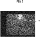
- FIG. 5 is a view showing an example of a standard image representing a designated image portion for counting a valid parallax value.
- a random pattern is projected to the imaging region.
- a rectangular image portion including a workpiece as a target is set as the designated image portion as shown by the frame B in FIG. 5 .
- a ratio of the image portion to the image portion showing the workpiece is high inside the designated image portion. In this case, the proportion of the valid parallax value of the image portion except the image portion showing the workpiece is increased.
- the relationship between the exposure time corresponding to the maximum number of valid parallax values of the designated image portion and the exposure time corresponding to the maximum number of valid parallax values of the image portion showing the workpiece is lowered. Consequently, even when the exposure time corresponding to the maximum number of valid parallax values of the designated image portion is set, the most suitable exposure time for improving the recognition process of the workpiece may not be set.
- FIG. 6 is a flowchart showing a flow of the exposure amount control in this modified example.
- the basic flow of the exposure amount control in this modified example is similar to that of the above embodiment.
- a parallax value in the predetermined designated parallax value range is only extracted (S1).
- This designated parallax value range includes the parallax value corresponding to a distance to the workpiece placed on a floor, and is set to a range excluding the parallax value corresponding to a distance to the floor on which the workpiece is placed. More specifically, when the distance to the floor is 1 m and the height of the workpiece is 25 mm, the designated parallax value range is set to a parallax value range corresponding to a distance of 950 to 995 mm.
- the parallax point obtained by counting the number of parallax values extracted as described above is calculated (S12).
- the number of parallax values for the image portion excluding the image portion of the floor in the designated image portion namely, the number of the parallax values corresponding to the image portion of the workpiece can be therefore appropriately counted.
- the most suitable exposure time for improving the recognition process of the workpiece can be obtained.
- the random pattern is projected to the imaging region of the camera unit 100 to improve the accuracy of the matching process.
- it is not always necessary to project the random pattern.
- the most suitable exposure time corresponding to the maximum number of valid parallax values for the image portion of the target can be set in a time shorter than that of the conventional device.
- An imaging apparatus includes a plurality of imaging sections such as the cameras 101A and 101B that image an imaging region, a parallax information generator such as the parallax information calculator 202 that generates parallax information based on a plurality of images imaged by a plurality of imaging sections, and an exposure amount controller as the parallax point calculator 203 and the exposure time controller 204 that determine an exposure amount such as the exposure time for use in a plurality of imaging sections in a subsequent imaging operation to increase the number of parallax values (parallax point) contained in a parallax value group of an image portion showing a target in the imaging region, wherein the exposure amount controller executes parallax information obtaining control that obtains the parallax information corresponding to a plurality of exposure amounts generated based on the images imaged by the imaging sections with a plurality of exposure amounts, and executes exposure amount identifying control that identifies the exposure amount corresponding to the parallax information having the maximum number of parallax values in the obtained
- the parallax information corresponding to a plurality of exposure amounts is obtained by executing the parallax information obtaining control, and then the exposure amount corresponding to the parallax information having the maximum number of parallax values is identified by the exposure amount identifying control.
- the exposure amount for use in the imaging sections in the subsequent imaging operation is therefore determined based on the identified exposure amount. Accordingly, by appropriately setting a plurality of exposure amounts for use in the parallax information obtaining control, the most suitable exposure amount can be determined by the one-time exposure amount control even when the most suitable exposure amount corresponding to the maximum number of valid parallax values for the image portion of the target significantly differs from the exposure amount which has been set so far.
- a plurality of imaging operations is required for obtaining the parallax information corresponding to a plurality of exposure amounts during the one-time exposure amount control. For this reason, a time required for the one-time exposure amount control becomes longer than that of the exposure amount control described in Patent Literature 1 which obtains only the parallax information corresponding to one exposure amount in the one-time exposure amount control (namely, one-time imaging operation).
- the imaging operation can be continuously executed in a plurality of exposure amounts during the one-time exposure amount control.
- the exposure amount control of this example can be applied to an in-vehicle equipment control system to which the imaging apparatus described in Patent Literature 1 is applied.
- the recognition process of the target is executed by continuously generating the parallax information based on each of the images obtained by the continuous imaging operations.
- a plurality of imaging operations is required until the exposure amount control is completed.
- the exposure amounts set by the imaging operations include an inappropriate exposure amount, appropriate parallax information cannot be obtained in such an inappropriate exposure amount. Even in this case, when the present exposure amount significantly differs from the most suitable exposure amount, the time required for setting the most suitable exposure amount is shorter than that of the exposure amount control described in Patent Literature 1.
- a period which cannot obtain appropriate parallax information is shorter than that of the exposure time control described in Patent Literature 1, so that the recognition process of the target can be improved compared to the exposure amount control described in Patent Literature 1 even when the recognition process of the target is executed by continuously generating the parallax information from each of the images obtained through the continuous imaging operations.
- the exposure amount controller determines an exposure amount higher than the identified exposure amount by the exposure amount identifying control as the exposure amount for use in the imaging sections in the subsequent imaging operation.
- the exposure amount controller uses three or more exposure times based on a geometric progression set in a predetermined exposure time range as a plurality of exposure amounts for use in the parallax information obtaining control.
- the number of parallax values can be obtained at the exposure amount interval in a range having a relatively small exposure amount (dark target), which is shorter than that in a range having a relatively large exposure amount (bright target).
- the pixel value (brightness value) of the image is saturated, so that the number of valid pixel values lowers the number of valid pixel values in the range having a relatively small exposure amount.
- the most suitable exposure amount is often obtained in the range having a relatively small exposure amount.
- the exposure amount identifying control identifies the exposure amount corresponding to the parallax information having the maximum number of parallax values for the image portion (designated image portion) designated by a predetermined image portion designation condition.
- the predetermined image portion designation condition by setting the predetermined image portion designation condition to obtain the designated image portion including the image portion showing the target and excluding the image portion which does not show the target as much as possible, the most suitable exposure time for discriminating the target can be easily set.
- the exposure amount identifying control identifies the exposure amount corresponding to the parallax information having the maximum number of parallax values in a parallax value range (designated parallax value range) designated by a predetermined parallax value range designation condition.
- the number of parallax values of the image portion showing the target can be obtained, so that the most suitable exposure amount for discriminating the target can be easily set.
- An imaging method includes a step of generating parallax information based on a plurality of images imaged by a plurality of imaging sections that images an imaging region; and a step of executing exposure amount control that determines an exposure amount for use in the plurality of imaging sections in a subsequent imaging operation to increase a number of parallax values contained in a parallax value group of an image portion showing a target in the imaging region, wherein the step of executing exposure amount control executes parallax information obtaining control that obtains the parallax information corresponding to a plurality of exposure amounts generated based on the images imaged by the imaging sections with the plurality of exposure amounts, and executes exposure amount identifying control that identifies the exposure amount corresponding to the parallax information having a maximum number of parallax values in the obtained parallax information to determine the exposure amount for use in the imaging sections in the subsequent imaging operation based on the identified exposure amount.
- the most suitable exposure amount can be determined by the one-time exposure amount control even when the most suitable exposure amount corresponding to the maximum number of valid parallax values for the image portion of the target significantly differs from the exposure amount which has been set so far.
- the time required for setting the most suitable exposure amount can be shortened compared to the exposure amount control described in Patent Literature 1.
- a non-transitory computer-readable computer medium storing an imaging operation control program that operates a computer of an imaging apparatus including a plurality of imaging sections that images an imaging region
- the program operates the computer as a parallax information generator that generates parallax information based on a plurality of images imaged by the plurality of imaging sections, and an exposure amount controller that determines an exposure amount for use in the plurality of imaging sections in a subsequent imaging operation to increase a number of parallax values contained in a parallax value group of an image portion showing a target in the imaging region
- the exposure amount controller executes parallax information obtaining control that obtains the parallax information corresponding to a plurality of exposure amounts generated based on the images imaged by the imaging sections with the plurality of exposure amounts, and executes exposure amount identifying control that identifies the exposure amount corresponding to the parallax information having a maximum number of parallax values in the obtained parallax information to determine the exposure amount for use in the imaging sections in the
- the most suitable exposure amount can be determined by the one-time exposure amount control even when the most suitable exposure amount corresponding to the maximum number of valid parallax values for the image portion of the target significantly differs from the exposure amount which has been set so far.
- the time required for setting the most suitable exposure amount can be shortened compared to the exposure amount control described in Patent Literature 1.
- this program can be recorded in a recording medium such as a CD-ROM to be distributed and acquired.
- Signals having the program transmitted by a predetermined transmitting device can be delivered and received via a public phone line, dedicated line, and transmitting medium such as communication network. In this delivering, at least a part of the computer program is transmitted to the transmitting medium. Namely, it is not always necessary for all of the data of the computer program temporarily to exist in the transmitting medium.
- the signals having the program are computer data signals realized in a predetermined carrier wave containing the computer program.
- a method of transmitting the computer program from a predetermined transmitting device includes continuous transmission of data constituting a program and intermittent transmission of data constituting a program.
Landscapes
- Engineering & Computer Science (AREA)
- Multimedia (AREA)
- Signal Processing (AREA)
- Human Computer Interaction (AREA)
- Length Measuring Devices By Optical Means (AREA)
- Studio Devices (AREA)
- Transforming Light Signals Into Electric Signals (AREA)
Claims (7)
- Bildgebungsvorrichtung für ein Roboter-Kommissioniersystem umfassend:eine Vielzahl von Bildgebungsabschnitten (101A und 101B), die einen Bildgebungsbereich abbilden;einen Parallaxeninformationsgenerator (202), der Parallaxeninformation basierend auf einer Vielzahl von Bildern erzeugt, die durch die Vielzahl von Bildgebungsabschnitten (101A und 101B) abgebildet werden; undeine Belichtungsmengensteuerung (203 und 204), die eine Belichtungsmenge zur Verwendung in der Vielzahl von Bildgebungsabschnitten (101A und 101B) in einem nachfolgenden Bildgebungsbetrieb bestimmt, um eine Anzahl gültiger Parallaxenwerte zu erhöhen, die in einer Parallaxenwertgruppe eines Bildabschnitts enthalten, die ein Ziel in dem Bildgebungsbereich zeigen, wobeidie Belichtungsmengensteuerung (203 und 204) eine Parallaxeninformations-Erhaltungssteuerung ausführt, die die Parallaxeninformationen entsprechend einer Vielzahl von Belichtungsmengen erhält, die basierend auf den Bildern erzeugt werden, die von den Bildgebungsabschnitten mit der Vielzahl von Belichtungsmengen abgebildet werden, und dadurch gekennzeichnet, dass die Belichtungsmengensteuerung (203 und 204) eine Belichtungsmengenidentifizierungssteuerung ausführt, die die Belichtungsmenge identifiziert, die den Parallaxeninformationen mit einer maximalen Anzahl gültiger Parallaxenwerte in den erhaltenen Parallaxeninformation entspricht, um die Belichtungsmenge zur Verwendung in den Bildgebungsabschnitten in dem nachfolgenden Bildgebungsbetrieb basierend auf der identifizierten Belichtungsmenge zu bestimmen.
- Bildgebungsvorrichtung nach Anspruch 1, wobei
die Belichtungsmengensteuerung (203 und 204) eine Belichtungsmenge bestimmt, die höher als die identifizierte Belichtungsmenge ist, durch die Belichtungsmengen-Identifizierungssteuerung als die Belichtungsmenge zur Verwendung in den Bildgebungsabschnitten in dem nachfolgenden Bildgebungsbetrieb. - Bildgebungsvorrichtung nach Anspruch 1 oder 2, wobei
die Belichtungsmengensteuerung (203 und 204) drei oder mehr Belichtungszeiten basierend auf einem geometrischen Verlauf verwendet, der in einem vorbestimmten Belichtungszeitbereich eingestellt ist, als die Vielzahl von Belichtungsmengen zur Verwendung in der Parallaxeninformations-Erhaltungssteuerung. - Bildgebungsvorrichtung nach einem der Ansprüche 1 bis 3, wobei
die Belichtungsmengen-Identifizierungssteuerung die Belichtungsmenge identifiziert, die den Parallaxeninformationen mit der maximalen Anzahl gültiger Parallaxenwerte für den Bildabschnitt entspricht, der durch eine vorbestimmte Bildabschnitt-Benennungsbedingung benannt wird. - Bildgebungsvorrichtung nach einem der Ansprüche 1 bis 4, wobei
die Belichtungsmengen-Identifizierungssteuerung die Belichtungsmenge identifiziert, die den Parallaxeninformationen mit der maximalen Anzahl gültiger Parallaxenwerte in einem Parallaxenwertbereich entspricht, der durch eine vorbestimmte Parallaxenwert-Benennungsbedingung benannt wird. - Bildgebungsverfahren für ein Roboter-Kommissioniersystem umfassend:einen Schritt zum Erzeugen von Parallaxeninformationen basierend auf der Vielzahl von Bildern, die von einer Vielzahl von Bildgebungsabschnitten abgebildet werden, die einen Bildgebungsbereich abbilden; undeinen Schritt des Ausführens einer Belichtungsmengensteuerung, die eine Belichtungsmenge zur Verwendung in der Vielzahl von Bildgebungsabschnitten in einem nachfolgenden Bildgebungsbetrieb bestimmt, um eine Anzahl gültiger Parallaxenwerte zu erhöhen, die in einer Parallaxenwertgruppe eines Bildabschnitts enthalten, die ein Ziel in dem Bildgebungsbereich zeigen, wobeider Schritt des Ausführens einer Belichtungsmengensteuerung eine Parallaxeninformations-Erhaltungssteuerung ausführt, die die Parallaxeninformation entsprechend einer Vielzahl von Belichtungsmengen erhält, die basierend auf den Bildern erzeugt werden, die durch die Bildgebungsabschnitte mit der Vielzahl von Belichtungsmengen abgebildet werden,dadurch gekennzeichnet, dass der Schritt des Ausführens der Belichtungsmengensteuerungeine Belichtungsmengen-Identifizierungssteuerung ausführt, die die Belichtungsmenge identifiziert, die der Parallaxeninformation mit einer maximalen Anzahl gültiger Parallaxenwerte in der erhaltenen Parallaxeninformation entspricht, um die Belichtungsmenge zur Verwendung in den Bildgebungsabschnitten in dem nachfolgenden Bildgebungsbetrieb basierend auf der identifizierten Belichtungsmenge zu bestimmen.
- Nichtflüchtiges computerlesbares Computermedium, das ein Bildgebungsbetriebssteuerprogramm speichert, das Anweisungen umfasst, um die Bildgebungsvorrichtung nach Anspruch 1 zu veranlassen, die Schritte des Verfahrens nach Anspruch 6 auszuführen.
Applications Claiming Priority (1)
| Application Number | Priority Date | Filing Date | Title |
|---|---|---|---|
| JP2015007721A JP6493787B2 (ja) | 2015-01-19 | 2015-01-19 | 撮像装置、撮像方法及び撮像動作制御プログラム |
Publications (2)
| Publication Number | Publication Date |
|---|---|
| EP3046321A1 EP3046321A1 (de) | 2016-07-20 |
| EP3046321B1 true EP3046321B1 (de) | 2020-03-04 |
Family
ID=55221272
Family Applications (1)
| Application Number | Title | Priority Date | Filing Date |
|---|---|---|---|
| EP16151121.7A Active EP3046321B1 (de) | 2015-01-19 | 2016-01-13 | Abbildungsvorrichtung, abbildungsverfahren und abbildungsoperationsteuerungsprogramm |
Country Status (3)
| Country | Link |
|---|---|
| US (1) | US9781352B2 (de) |
| EP (1) | EP3046321B1 (de) |
| JP (1) | JP6493787B2 (de) |
Families Citing this family (9)
| Publication number | Priority date | Publication date | Assignee | Title |
|---|---|---|---|---|
| KR101679279B1 (ko) * | 2015-09-10 | 2016-11-24 | 한국과학기술원 | 카메라 노출 조절 장치 및 방법 |
| WO2018077156A1 (en) | 2016-10-26 | 2018-05-03 | Zhejiang Dahua Technology Co., Ltd. | Systems and methods for exposure control |
| CN106686319B (zh) * | 2016-12-27 | 2019-07-16 | 浙江大华技术股份有限公司 | 一种图像曝光的控制方法及其装置 |
| US11194227B2 (en) | 2016-12-27 | 2021-12-07 | Zhejiang Dahua Technology Co., Ltd. | Systems and methods for exposure control |
| WO2018121313A1 (en) | 2016-12-27 | 2018-07-05 | Zhejiang Dahua Technology Co., Ltd. | Systems and methods for exposure control |
| JP7233508B2 (ja) * | 2017-07-31 | 2023-03-06 | 株式会社キーエンス | 形状測定装置及び形状測定方法 |
| JP6970551B2 (ja) * | 2017-07-31 | 2021-11-24 | 株式会社キーエンス | 形状測定装置及び形状測定方法 |
| JP6770254B2 (ja) * | 2018-02-07 | 2020-10-14 | オムロン株式会社 | 3次元測定装置、3次元測定方法及び3次元測定プログラム |
| JP6959277B2 (ja) | 2019-02-27 | 2021-11-02 | ファナック株式会社 | 3次元撮影装置および3次元撮影条件調整方法 |
Family Cites Families (10)
| Publication number | Priority date | Publication date | Assignee | Title |
|---|---|---|---|---|
| JP2518780B2 (ja) | 1992-08-21 | 1996-07-31 | 村田機械株式会社 | パレタイジング方法 |
| JPH099154A (ja) * | 1995-06-23 | 1997-01-10 | Kokusai Electric Co Ltd | 画像入力装置 |
| JP4032262B2 (ja) * | 1996-05-13 | 2008-01-16 | 株式会社ニコン | 電子カメラ |
| US7561731B2 (en) * | 2004-12-27 | 2009-07-14 | Trw Automotive U.S. Llc | Method and apparatus for enhancing the dynamic range of a stereo vision system |
| JP2011044927A (ja) * | 2009-08-21 | 2011-03-03 | Ihi Corp | 画像合成方法と装置 |
| JP5411842B2 (ja) * | 2010-12-07 | 2014-02-12 | シャープ株式会社 | 撮像装置 |
| EP2757415B1 (de) * | 2011-09-13 | 2017-12-20 | Fujifilm Corporation | 3d-abbildungsvorrichtung |
| JP5898535B2 (ja) | 2012-03-13 | 2016-04-06 | 富士重工業株式会社 | 撮像ユニットの露光制御装置 |
| JP2014130429A (ja) * | 2012-12-28 | 2014-07-10 | Ricoh Co Ltd | 撮像装置及び立体物領域検出用プログラム |
| US9774789B2 (en) * | 2013-03-08 | 2017-09-26 | Fotonation Cayman Limited | Systems and methods for high dynamic range imaging using array cameras |
-
2015
- 2015-01-19 JP JP2015007721A patent/JP6493787B2/ja not_active Expired - Fee Related
-
2016
- 2016-01-08 US US14/991,488 patent/US9781352B2/en active Active
- 2016-01-13 EP EP16151121.7A patent/EP3046321B1/de active Active
Non-Patent Citations (1)
| Title |
|---|
| None * |
Also Published As
| Publication number | Publication date |
|---|---|
| US20160212316A1 (en) | 2016-07-21 |
| JP2016134723A (ja) | 2016-07-25 |
| EP3046321A1 (de) | 2016-07-20 |
| JP6493787B2 (ja) | 2019-04-03 |
| US9781352B2 (en) | 2017-10-03 |
Similar Documents
| Publication | Publication Date | Title |
|---|---|---|
| EP3046321B1 (de) | Abbildungsvorrichtung, abbildungsverfahren und abbildungsoperationsteuerungsprogramm | |
| US12267480B2 (en) | Stereo imaging device with image distortion correction | |
| US9621786B2 (en) | Image processing apparatus, image processing method, image processing program, and image pickup apparatus acquiring a focusing distance from a plurality of images | |
| US10582180B2 (en) | Depth imaging correction apparatus, imaging apparatus, and depth image correction method | |
| US10455149B2 (en) | Image processing apparatus, image processing apparatus control method, image pickup apparatus, and image pickup apparatus control method | |
| US8855417B2 (en) | Method and device for shape extraction, and size measuring device and distance measuring device | |
| EP1528797A2 (de) | Bildverarbeitungsvorrichtung, Bildaufnahmesystem und Bildverarbeitungsverfahren | |
| US8830381B2 (en) | Imaging device and method to provide bokeh effect in captured image by determining distance and focus of captured objects in secondary image sequence | |
| US20190204073A1 (en) | Distance information processing apparatus, imaging apparatus, distance information processing method and program | |
| US8810665B2 (en) | Imaging device and method to detect distance information for blocks in secondary images by changing block size | |
| US11398045B2 (en) | Three-dimensional imaging device and three-dimensional imaging condition adjusting method | |
| JP2014120122A (ja) | 領域抽出装置、領域抽出方法、及びコンピュータプログラム | |
| JP6529360B2 (ja) | 画像処理装置、撮像装置、画像処理方法およびプログラム | |
| KR101439013B1 (ko) | 스테레오 영상 처리 장치 및 방법 | |
| US9094581B2 (en) | Imaging device and distance information detecting method | |
| JP2011071925A (ja) | 移動体追尾装置および方法 | |
| US20130076868A1 (en) | Stereoscopic imaging apparatus, face detection apparatus and methods of controlling operation of same | |
| JP2002116008A (ja) | 距離測定装置及び映像監視装置 | |
| CN106454066B (zh) | 图像处理设备及其控制方法 | |
| EP2727077A1 (de) | System und verfahren zur auflösungsverbesserung | |
| CN114783041A (zh) | 目标对象识别方法、电子设备和计算机可读存储介质 | |
| JP6448324B2 (ja) | 画像処理装置、撮像装置、画像処理システム、画像処理方法、および画像処理プログラム | |
| KR101203478B1 (ko) | 유효구간 자동설정을 통한 유효대상 추출방법 | |
| JP7437915B2 (ja) | 画像処理装置、撮像装置、画像処理方法、及びプログラム | |
| JP2016099322A (ja) | 撮像装置、撮像装置の制御方法およびプログラム |
Legal Events
| Date | Code | Title | Description |
|---|---|---|---|
| PUAI | Public reference made under article 153(3) epc to a published international application that has entered the european phase |
Free format text: ORIGINAL CODE: 0009012 |
|
| 17P | Request for examination filed |
Effective date: 20160113 |
|
| AK | Designated contracting states |
Kind code of ref document: A1 Designated state(s): AL AT BE BG CH CY CZ DE DK EE ES FI FR GB GR HR HU IE IS IT LI LT LU LV MC MK MT NL NO PL PT RO RS SE SI SK SM TR |
|
| AX | Request for extension of the european patent |
Extension state: BA ME |
|
| STAA | Information on the status of an ep patent application or granted ep patent |
Free format text: STATUS: EXAMINATION IS IN PROGRESS |
|
| 17Q | First examination report despatched |
Effective date: 20171206 |
|
| RIC1 | Information provided on ipc code assigned before grant |
Ipc: H04N 5/235 20060101AFI20190808BHEP Ipc: H04N 13/00 20180101ALI20190808BHEP |
|
| GRAP | Despatch of communication of intention to grant a patent |
Free format text: ORIGINAL CODE: EPIDOSNIGR1 |
|
| STAA | Information on the status of an ep patent application or granted ep patent |
Free format text: STATUS: GRANT OF PATENT IS INTENDED |
|
| INTG | Intention to grant announced |
Effective date: 20191011 |
|
| GRAS | Grant fee paid |
Free format text: ORIGINAL CODE: EPIDOSNIGR3 |
|
| GRAA | (expected) grant |
Free format text: ORIGINAL CODE: 0009210 |
|
| STAA | Information on the status of an ep patent application or granted ep patent |
Free format text: STATUS: THE PATENT HAS BEEN GRANTED |
|
| AK | Designated contracting states |
Kind code of ref document: B1 Designated state(s): AL AT BE BG CH CY CZ DE DK EE ES FI FR GB GR HR HU IE IS IT LI LT LU LV MC MK MT NL NO PL PT RO RS SE SI SK SM TR |
|
| REG | Reference to a national code |
Ref country code: GB Ref legal event code: FG4D |
|
| REG | Reference to a national code |
Ref country code: CH Ref legal event code: EP |
|
| REG | Reference to a national code |
Ref country code: AT Ref legal event code: REF Ref document number: 1241773 Country of ref document: AT Kind code of ref document: T Effective date: 20200315 |
|
| REG | Reference to a national code |
Ref country code: DE Ref legal event code: R096 Ref document number: 602016030882 Country of ref document: DE |
|
| REG | Reference to a national code |
Ref country code: IE Ref legal event code: FG4D |
|
| PG25 | Lapsed in a contracting state [announced via postgrant information from national office to epo] |
Ref country code: NO Free format text: LAPSE BECAUSE OF FAILURE TO SUBMIT A TRANSLATION OF THE DESCRIPTION OR TO PAY THE FEE WITHIN THE PRESCRIBED TIME-LIMIT Effective date: 20200604 Ref country code: RS Free format text: LAPSE BECAUSE OF FAILURE TO SUBMIT A TRANSLATION OF THE DESCRIPTION OR TO PAY THE FEE WITHIN THE PRESCRIBED TIME-LIMIT Effective date: 20200304 Ref country code: FI Free format text: LAPSE BECAUSE OF FAILURE TO SUBMIT A TRANSLATION OF THE DESCRIPTION OR TO PAY THE FEE WITHIN THE PRESCRIBED TIME-LIMIT Effective date: 20200304 |
|
| REG | Reference to a national code |
Ref country code: NL Ref legal event code: MP Effective date: 20200304 |
|
| PG25 | Lapsed in a contracting state [announced via postgrant information from national office to epo] |
Ref country code: SE Free format text: LAPSE BECAUSE OF FAILURE TO SUBMIT A TRANSLATION OF THE DESCRIPTION OR TO PAY THE FEE WITHIN THE PRESCRIBED TIME-LIMIT Effective date: 20200304 Ref country code: LV Free format text: LAPSE BECAUSE OF FAILURE TO SUBMIT A TRANSLATION OF THE DESCRIPTION OR TO PAY THE FEE WITHIN THE PRESCRIBED TIME-LIMIT Effective date: 20200304 Ref country code: GR Free format text: LAPSE BECAUSE OF FAILURE TO SUBMIT A TRANSLATION OF THE DESCRIPTION OR TO PAY THE FEE WITHIN THE PRESCRIBED TIME-LIMIT Effective date: 20200605 Ref country code: BG Free format text: LAPSE BECAUSE OF FAILURE TO SUBMIT A TRANSLATION OF THE DESCRIPTION OR TO PAY THE FEE WITHIN THE PRESCRIBED TIME-LIMIT Effective date: 20200604 Ref country code: HR Free format text: LAPSE BECAUSE OF FAILURE TO SUBMIT A TRANSLATION OF THE DESCRIPTION OR TO PAY THE FEE WITHIN THE PRESCRIBED TIME-LIMIT Effective date: 20200304 |
|
| REG | Reference to a national code |
Ref country code: LT Ref legal event code: MG4D |
|
| PG25 | Lapsed in a contracting state [announced via postgrant information from national office to epo] |
Ref country code: NL Free format text: LAPSE BECAUSE OF FAILURE TO SUBMIT A TRANSLATION OF THE DESCRIPTION OR TO PAY THE FEE WITHIN THE PRESCRIBED TIME-LIMIT Effective date: 20200304 |
|
| PG25 | Lapsed in a contracting state [announced via postgrant information from national office to epo] |
Ref country code: ES Free format text: LAPSE BECAUSE OF FAILURE TO SUBMIT A TRANSLATION OF THE DESCRIPTION OR TO PAY THE FEE WITHIN THE PRESCRIBED TIME-LIMIT Effective date: 20200304 Ref country code: LT Free format text: LAPSE BECAUSE OF FAILURE TO SUBMIT A TRANSLATION OF THE DESCRIPTION OR TO PAY THE FEE WITHIN THE PRESCRIBED TIME-LIMIT Effective date: 20200304 Ref country code: EE Free format text: LAPSE BECAUSE OF FAILURE TO SUBMIT A TRANSLATION OF THE DESCRIPTION OR TO PAY THE FEE WITHIN THE PRESCRIBED TIME-LIMIT Effective date: 20200304 Ref country code: PT Free format text: LAPSE BECAUSE OF FAILURE TO SUBMIT A TRANSLATION OF THE DESCRIPTION OR TO PAY THE FEE WITHIN THE PRESCRIBED TIME-LIMIT Effective date: 20200729 Ref country code: SM Free format text: LAPSE BECAUSE OF FAILURE TO SUBMIT A TRANSLATION OF THE DESCRIPTION OR TO PAY THE FEE WITHIN THE PRESCRIBED TIME-LIMIT Effective date: 20200304 Ref country code: SK Free format text: LAPSE BECAUSE OF FAILURE TO SUBMIT A TRANSLATION OF THE DESCRIPTION OR TO PAY THE FEE WITHIN THE PRESCRIBED TIME-LIMIT Effective date: 20200304 Ref country code: CZ Free format text: LAPSE BECAUSE OF FAILURE TO SUBMIT A TRANSLATION OF THE DESCRIPTION OR TO PAY THE FEE WITHIN THE PRESCRIBED TIME-LIMIT Effective date: 20200304 Ref country code: RO Free format text: LAPSE BECAUSE OF FAILURE TO SUBMIT A TRANSLATION OF THE DESCRIPTION OR TO PAY THE FEE WITHIN THE PRESCRIBED TIME-LIMIT Effective date: 20200304 Ref country code: IS Free format text: LAPSE BECAUSE OF FAILURE TO SUBMIT A TRANSLATION OF THE DESCRIPTION OR TO PAY THE FEE WITHIN THE PRESCRIBED TIME-LIMIT Effective date: 20200704 |
|
| REG | Reference to a national code |
Ref country code: AT Ref legal event code: MK05 Ref document number: 1241773 Country of ref document: AT Kind code of ref document: T Effective date: 20200304 |
|
| REG | Reference to a national code |
Ref country code: DE Ref legal event code: R097 Ref document number: 602016030882 Country of ref document: DE |
|
| PLBE | No opposition filed within time limit |
Free format text: ORIGINAL CODE: 0009261 |
|
| STAA | Information on the status of an ep patent application or granted ep patent |
Free format text: STATUS: NO OPPOSITION FILED WITHIN TIME LIMIT |
|
| PG25 | Lapsed in a contracting state [announced via postgrant information from national office to epo] |
Ref country code: IT Free format text: LAPSE BECAUSE OF FAILURE TO SUBMIT A TRANSLATION OF THE DESCRIPTION OR TO PAY THE FEE WITHIN THE PRESCRIBED TIME-LIMIT Effective date: 20200304 Ref country code: AT Free format text: LAPSE BECAUSE OF FAILURE TO SUBMIT A TRANSLATION OF THE DESCRIPTION OR TO PAY THE FEE WITHIN THE PRESCRIBED TIME-LIMIT Effective date: 20200304 Ref country code: DK Free format text: LAPSE BECAUSE OF FAILURE TO SUBMIT A TRANSLATION OF THE DESCRIPTION OR TO PAY THE FEE WITHIN THE PRESCRIBED TIME-LIMIT Effective date: 20200304 |
|
| 26N | No opposition filed |
Effective date: 20201207 |
|
| PG25 | Lapsed in a contracting state [announced via postgrant information from national office to epo] |
Ref country code: SI Free format text: LAPSE BECAUSE OF FAILURE TO SUBMIT A TRANSLATION OF THE DESCRIPTION OR TO PAY THE FEE WITHIN THE PRESCRIBED TIME-LIMIT Effective date: 20200304 Ref country code: PL Free format text: LAPSE BECAUSE OF FAILURE TO SUBMIT A TRANSLATION OF THE DESCRIPTION OR TO PAY THE FEE WITHIN THE PRESCRIBED TIME-LIMIT Effective date: 20200304 |
|
| PG25 | Lapsed in a contracting state [announced via postgrant information from national office to epo] |
Ref country code: MC Free format text: LAPSE BECAUSE OF FAILURE TO SUBMIT A TRANSLATION OF THE DESCRIPTION OR TO PAY THE FEE WITHIN THE PRESCRIBED TIME-LIMIT Effective date: 20200304 |
|
| REG | Reference to a national code |
Ref country code: CH Ref legal event code: PL |
|
| PG25 | Lapsed in a contracting state [announced via postgrant information from national office to epo] |
Ref country code: LU Free format text: LAPSE BECAUSE OF NON-PAYMENT OF DUE FEES Effective date: 20210113 |
|
| REG | Reference to a national code |
Ref country code: BE Ref legal event code: MM Effective date: 20210131 |
|
| PG25 | Lapsed in a contracting state [announced via postgrant information from national office to epo] |
Ref country code: CH Free format text: LAPSE BECAUSE OF NON-PAYMENT OF DUE FEES Effective date: 20210131 Ref country code: LI Free format text: LAPSE BECAUSE OF NON-PAYMENT OF DUE FEES Effective date: 20210131 |
|
| PG25 | Lapsed in a contracting state [announced via postgrant information from national office to epo] |
Ref country code: IE Free format text: LAPSE BECAUSE OF NON-PAYMENT OF DUE FEES Effective date: 20210113 |
|
| PG25 | Lapsed in a contracting state [announced via postgrant information from national office to epo] |
Ref country code: BE Free format text: LAPSE BECAUSE OF NON-PAYMENT OF DUE FEES Effective date: 20210131 |
|
| REG | Reference to a national code |
Ref country code: DE Ref legal event code: R079 Ref document number: 602016030882 Country of ref document: DE Free format text: PREVIOUS MAIN CLASS: H04N0005235000 Ipc: H04N0023700000 |
|
| PG25 | Lapsed in a contracting state [announced via postgrant information from national office to epo] |
Ref country code: HU Free format text: LAPSE BECAUSE OF FAILURE TO SUBMIT A TRANSLATION OF THE DESCRIPTION OR TO PAY THE FEE WITHIN THE PRESCRIBED TIME-LIMIT; INVALID AB INITIO Effective date: 20160113 |
|
| P01 | Opt-out of the competence of the unified patent court (upc) registered |
Effective date: 20230522 |
|
| PG25 | Lapsed in a contracting state [announced via postgrant information from national office to epo] |
Ref country code: CY Free format text: LAPSE BECAUSE OF FAILURE TO SUBMIT A TRANSLATION OF THE DESCRIPTION OR TO PAY THE FEE WITHIN THE PRESCRIBED TIME-LIMIT Effective date: 20200304 |
|
| PG25 | Lapsed in a contracting state [announced via postgrant information from national office to epo] |
Ref country code: MK Free format text: LAPSE BECAUSE OF FAILURE TO SUBMIT A TRANSLATION OF THE DESCRIPTION OR TO PAY THE FEE WITHIN THE PRESCRIBED TIME-LIMIT Effective date: 20200304 |
|
| PG25 | Lapsed in a contracting state [announced via postgrant information from national office to epo] |
Ref country code: MT Free format text: LAPSE BECAUSE OF FAILURE TO SUBMIT A TRANSLATION OF THE DESCRIPTION OR TO PAY THE FEE WITHIN THE PRESCRIBED TIME-LIMIT Effective date: 20200304 |
|
| PGFP | Annual fee paid to national office [announced via postgrant information from national office to epo] |
Ref country code: DE Payment date: 20250121 Year of fee payment: 10 |
|
| PGFP | Annual fee paid to national office [announced via postgrant information from national office to epo] |
Ref country code: FR Payment date: 20250127 Year of fee payment: 10 |
|
| PGFP | Annual fee paid to national office [announced via postgrant information from national office to epo] |
Ref country code: GB Payment date: 20250128 Year of fee payment: 10 |
|
| PG25 | Lapsed in a contracting state [announced via postgrant information from national office to epo] |
Ref country code: TR Free format text: LAPSE BECAUSE OF FAILURE TO SUBMIT A TRANSLATION OF THE DESCRIPTION OR TO PAY THE FEE WITHIN THE PRESCRIBED TIME-LIMIT Effective date: 20200304 |