EP3045578B1 - Sewing machine - Google Patents
Sewing machine Download PDFInfo
- Publication number
- EP3045578B1 EP3045578B1 EP14842648.9A EP14842648A EP3045578B1 EP 3045578 B1 EP3045578 B1 EP 3045578B1 EP 14842648 A EP14842648 A EP 14842648A EP 3045578 B1 EP3045578 B1 EP 3045578B1
- Authority
- EP
- European Patent Office
- Prior art keywords
- needle thread
- section
- thread
- needle
- segment
- Prior art date
- Legal status (The legal status is an assumption and is not a legal conclusion. Google has not performed a legal analysis and makes no representation as to the accuracy of the status listed.)
- Active
Links
- 238000009958 sewing Methods 0.000 title claims description 151
- 239000004744 fabric Substances 0.000 claims description 211
- 238000011144 upstream manufacturing Methods 0.000 claims description 129
- 230000007246 mechanism Effects 0.000 claims description 45
- 238000003780 insertion Methods 0.000 claims description 31
- 230000037431 insertion Effects 0.000 claims description 31
- 238000003860 storage Methods 0.000 claims description 19
- 230000001174 ascending effect Effects 0.000 description 44
- 230000008859 change Effects 0.000 description 20
- 238000000034 method Methods 0.000 description 10
- 239000000463 material Substances 0.000 description 9
- 230000005291 magnetic effect Effects 0.000 description 8
- 230000005540 biological transmission Effects 0.000 description 7
- 238000004090 dissolution Methods 0.000 description 7
- 239000000126 substance Substances 0.000 description 7
- 229920003002 synthetic resin Polymers 0.000 description 7
- 239000000057 synthetic resin Substances 0.000 description 7
- XEEYBQQBJWHFJM-UHFFFAOYSA-N Iron Chemical compound [Fe] XEEYBQQBJWHFJM-UHFFFAOYSA-N 0.000 description 6
- 229910052751 metal Inorganic materials 0.000 description 5
- 239000002184 metal Substances 0.000 description 5
- 238000005520 cutting process Methods 0.000 description 4
- 230000002950 deficient Effects 0.000 description 4
- 238000009956 embroidering Methods 0.000 description 4
- 125000006850 spacer group Chemical group 0.000 description 4
- 239000011162 core material Substances 0.000 description 3
- 230000003247 decreasing effect Effects 0.000 description 3
- 239000000835 fiber Substances 0.000 description 3
- 229910052742 iron Inorganic materials 0.000 description 3
- 238000004519 manufacturing process Methods 0.000 description 3
- 229910052782 aluminium Inorganic materials 0.000 description 2
- XAGFODPZIPBFFR-UHFFFAOYSA-N aluminium Chemical compound [Al] XAGFODPZIPBFFR-UHFFFAOYSA-N 0.000 description 2
- 238000005452 bending Methods 0.000 description 2
- 230000007423 decrease Effects 0.000 description 2
- 230000005294 ferromagnetic effect Effects 0.000 description 2
- 230000000977 initiatory effect Effects 0.000 description 2
- 239000003960 organic solvent Substances 0.000 description 2
- 238000000926 separation method Methods 0.000 description 2
- 229910001220 stainless steel Inorganic materials 0.000 description 2
- 239000010935 stainless steel Substances 0.000 description 2
- CYTYCFOTNPOANT-UHFFFAOYSA-N Perchloroethylene Chemical group ClC(Cl)=C(Cl)Cl CYTYCFOTNPOANT-UHFFFAOYSA-N 0.000 description 1
- 230000009471 action Effects 0.000 description 1
- 230000003028 elevating effect Effects 0.000 description 1
- 230000010354 integration Effects 0.000 description 1
- 238000005304 joining Methods 0.000 description 1
- 239000000696 magnetic material Substances 0.000 description 1
- 238000003672 processing method Methods 0.000 description 1
- 230000004044 response Effects 0.000 description 1
- 238000004904 shortening Methods 0.000 description 1
- 229950011008 tetrachloroethylene Drugs 0.000 description 1
- XLYOFNOQVPJJNP-UHFFFAOYSA-N water Substances O XLYOFNOQVPJJNP-UHFFFAOYSA-N 0.000 description 1
Images


Classifications
-
- D—TEXTILES; PAPER
- D05—SEWING; EMBROIDERING; TUFTING
- D05C—EMBROIDERING; TUFTING
- D05C11/00—Devices for guiding, feeding, handling, or treating the threads in embroidering machines; Machine needles; Operating or control mechanisms therefor
- D05C11/08—Thread-tensioning arrangements
-
- D—TEXTILES; PAPER
- D05—SEWING; EMBROIDERING; TUFTING
- D05C—EMBROIDERING; TUFTING
- D05C7/00—Special-purpose or automatic embroidering machines
-
- D—TEXTILES; PAPER
- D05—SEWING; EMBROIDERING; TUFTING
- D05B—SEWING
- D05B19/00—Programme-controlled sewing machines
- D05B19/02—Sewing machines having electronic memory or microprocessor control unit
- D05B19/04—Sewing machines having electronic memory or microprocessor control unit characterised by memory aspects
- D05B19/08—Arrangements for inputting stitch or pattern data to memory ; Editing stitch or pattern data
-
- D—TEXTILES; PAPER
- D05—SEWING; EMBROIDERING; TUFTING
- D05B—SEWING
- D05B19/00—Programme-controlled sewing machines
- D05B19/02—Sewing machines having electronic memory or microprocessor control unit
- D05B19/12—Sewing machines having electronic memory or microprocessor control unit characterised by control of operation of machine
-
- D—TEXTILES; PAPER
- D05—SEWING; EMBROIDERING; TUFTING
- D05B—SEWING
- D05B47/00—Needle-thread tensioning devices; Applications of tensometers
- D05B47/04—Automatically-controlled tensioning devices
-
- D—TEXTILES; PAPER
- D05—SEWING; EMBROIDERING; TUFTING
- D05C—EMBROIDERING; TUFTING
- D05C7/00—Special-purpose or automatic embroidering machines
- D05C7/02—Special-purpose or automatic embroidering machines with accessories for peculiar kinds of embroidery
Definitions
- the present invention relates to a sewing machine and, more particularly, to an embroidery sewing machine.
- Hitherto-known methods for creating hollow embroidery are to make embroidery while placing plate-shaped members on a cloth to be embroidered and, subsequently, to dissolve the plate-shaped member.
- a foundation cloth is embroidered by use of water-insoluble embroidery thread and an embroidery back thread. After the foundation cloth is further embroidered with an overlapping unwoven cloth and/or a woven cloth formed from water-soluble fiber, the water-soluble fiber is dissolved and removed in water whose dissolution temperature is higher than that of the water-soluble fiber by at least 10°C or more, thereby obtaining hollow embroidery.
- an embroidery patch internally including an organdy core material in an integrated manner is obtained through: an embroidery step of embroidering organdy with an overlapping synthetic resin plate which dissolves in an organic solvent; a separation step of cutting off unwanted portions of the synthetic resin plate other than the embroidered portion formed in the embroidery step; a plate dissolution step of dissolving and eliminating the synthetic resin plate still left in the embroidery by bringing the embroidered portion cut off in the separation step into contact with the organic solvent along with the organdy and the synthetic resin plate provided inside; and a heat-cutting step of cutting the organdy with heat along an outer brim of the embroidery.
- an embroidery method utilizing a spacer is to obtain hollow three-dimensional embroidery through the steps of: placing a spacer on a foundation cloth; sewing the foundation cloth with the embroidery thread by way of the spacer; and dissolving the spacer in tetrachloroethylene.
- Patent Document 4 and Patent Document 5 in connection with a sewing machine including: an upstream grip section section having an upstream grip section section main body for gripping a needle thread by pinching; a downstream grip section section that is placed at a downstream position on a needle thread path with reference to the upstream grip section section and that has a downstream grip section section main body which grips the needle thread by pinching; and a circular movement section for circularly moving the needle thread between the upstream grip section section main body and the downstream grip section section main body.
- the objective of the present invention is to provide a sewing machine which does not need the plate-shaped member to be superposed on the cloth to be embroidered; which does not need to dissolve the plate-shaped member; which enables adjustment of the length of the needle thread on a per-stitch basis; and which enables production of elaborate hollow embroidery.
- a sewing machine comprising:
- the circular movement arm performs circular movement through an angle corresponding to the stitch reference length, which is a stitch length achieved when the n+1 th stitch is fixed by the needle thread fixing section in the first segment.
- the needle thread having the length required for the n+1 th stitch is prepared between the cloth and the circular movement arm.
- the second needle thread portion is fixed by the needle thread fixing section. Therefore, there is no risk of the shuttle withdrawing the needle thread from the stitch fixed by the needle thread fixing section (i.e., the n th stitch).
- the upstream grip section stays closed, and the downstream grip section stays open. Accordingly, there is no fear of the needle thread being withdrawn from an upstream position with respect to the upstream grip section.
- the thread take-up lever ascends in the second segment.
- the circular movement arm performs circular movement in the first direction, thus withdrawing the needle thread from the n th stitch.
- the remaining length of the needle thread of the n th stitch correspondingly becomes shorter.
- the needle thread is held fixed by the needle thread fixing section. Therefore, the needle thread becomes folded back at the position of the needle thread fixing section.
- the sewing machine of the present invention creates hollow embroidery by fixing the needle thread with the thread hooking rod. Therefore, the plate-shaped member to be used for superposing the needle thread on the cloth to be embroidered is unnecessary by the needle thread fixing section, nor is required dissolution of the plate-shaped member. Moreover, the length of the needle thread can be controlled on a per-stitch basis by means of the angle of circular movement of the circular movement arm in the second segment. Therefore, there can be provided a sewing machine capable of creating elaborate hollow embroidery. The length of the needle thread (i.e., the remaining length of the needle thread) is made longer, thereby preventing excessive pulling of the cloth, which would otherwise be caused by making stitches, and the embroidered cloth does not become wavy (or uneven). Further, stitches can be made soft.
- the control section can also be embodied as follows. Specifically, “the control section (90) that controls the operation of the upstream drive section, the operation of the downstream drive section, the operation of the needle thread motor, and the operation of the needle thread fixing drive section (or can also be referred to as a "needle thread fixing section”) ; that, in the first segment which is at least the portion of a time segment from the top dead center of the shuttle to the bottom dead center of the shuttle, circularly moves the circular movement arm, by control of the needle thread motor, in the second direction through an angle corresponding to a stitch reference length which is the stitch needle thread length achieved while an n+1 th stitch next to a proximal n th stitch ("n" is an integer), among stitches already made in the cloth, is fixed to the needle thread fixing section; that, in the second segment which is at least a portion of a time segment from the bottom dead center of the shuttle to the top dead center of the shuttle, circularly moves the circular movement arm, by control of the needle thread motor, in
- control section can also be embodied as follows. Specifically, "a control section (90) that controls operation of the upstream drive section, operation of the downstream drive section, operation of the needle thread motor, and operation of the needle thread fixing drive section (or can also be called a “needle thread fixing section”) ; that, in the first segment which is at least a portion of a segment from the top dead center of the shuttle to the bottom dead center of the shuttle, circularly moves the circular movement arm, by control of the needle thread motor, in the second direction through an angle corresponding to a stitch reference length which is a stitch needle thread length achieved while the n+1 th stitch next to the proximal n th stitch ("n" is an integer), among the stitches already made in the cloth, is fixed to the needle thread fixing section; that, in the second segment which is at least a portion of the segment from the bottom dead center of the shuttle to the top dead center of the shuttle, circularly moves the circular movement arm, by control of the needle thread motor, in the first direction through an angle corresponding
- the first configuration is characterized by comprising a presser foot (12c) which moves between a cloth surface contact position where the presser foot contacts the cloth surface and a cloth surface apart position where the presser foot is apart from the cloth surface, and the presser foot is provided with the needle thread fixing section.
- the second configuration is characterized in that the presser foot has a presser foot main body (210) having a cloth surface contact section (216) (which can also be referred to as a "leading-end structure section,” and the same also applies to any counterparts throughout the specification) which contacts the cloth surface when the presser foot is at the cloth surface contact position; the needle thread fixing section has
- the third configuration can also be embodied as follows. Specifically, “the presser foot has the presser foot main body (210) having the cloth surface contact section (216) (which can also be referred to as a “leading-end structure section, " and the same also applies to any counterparts throughout the specification) that contacts the cloth surface when the presser foot is at the cloth surface contact position.
- the presser foot has the presser foot main body (210) having the cloth surface contact section (216) (which can also be referred to as a “leading-end structure section, " and the same also applies to any counterparts throughout the specification) that contacts the cloth surface when the presser foot is at the cloth surface contact position.
- the needle thread fixing section has the thread hooking rod support (231) that reciprocally moves in a second sideway direction orthogonal to the first sideway direction, while swaying in the first sideway direction with respect to the presser foot main body, by means of the crank mechanism to be driven by the needle thread fixing drive section; the rod-shaped thread hooking rod (236) fixed to the thread hooking rod support; and the needle thread receiving section (216f) provided at the position on the cloth surface contact section deviating toward the cloth surface with respect to the insertion position where the sewing needle is to be inserted and which fixes the needle thread by pinching the needle thread, hooked by the thread hooking rod, along with the thread hooking rod.
- the needle thread fixing drive section As a result of the needle thread fixing drive section being driven, the thread hooking rod support moves to and fro in the second sideway direction while swaying in the first sideway direction, whereby the thread hooking rod swivels.
- the needle thread fixing drive section stops driving at least in a segment from when the sewing thread is inserted into the cloth to when the shuttle hooks the needle thread, thereby achieving a fixed state where the thread hooking rod fixes the needle thread by pinching together with the needle thread receiving section.”
- the third configuration can also be embodied as follows. Specifically, "in relation to the second configuration, the presser foot has the presser foot main body (210) having the cloth surface contact section (216) that contacts the cloth surface when the sewing needle is inserted into the cloth and a main body structure section (214) formed closer to a rear side than the cloth surface contact section when one of the sideway direction is taken as a rear side of the presser foot.
- the needle thread fixing section has the thread hooking rod support (231) that reciprocally moves in a front-back direction while swaying in a right-left direction with respect to the main body structure section by means of the crank mechanism to be driven by the needle thread fixing drive section; the rod-shaped thread hooking rod (236) fixed to the thread hooking rod support; and the needle thread receiving section (216f) provided at the position on the cloth surface contact section deviating toward the cloth surface with respect to the insertion position where the sewing needle is to be inserted and which fixes the needle thread by pinching the needle thread hooked by the thread hooking rod, along with the thread hooking rod.
- the needle thread fixing drive section As a result of the needle thread fixing drive section being driven, the thread hooking rod support moves to and fro in the second sideway direction while swaying in the first sideway direction, whereby the thread hooking rod swivels.
- the needle thread fixing drive section stops driving at least in a segment from when the sewing thread is inserted into the cloth to when the shuttle hooks the needle thread, thereby achieving a fixed state where the thread hooking rod fixes the needle thread by pinching together with the needle thread receiving section.”
- the third configuration is characterized in that the thread hooking rod support reciprocally moves in a second sideway direction orthogonal to a first sideway direction, while swaying in the first sideway direction with respect to the presser foot main body, by means of a crank mechanism to be driven by the needle thread fixing drive section; and the thread hooking rod swivels as a result of the thread hooking rod support reciprocally moving in the second sideway direction while swaying in the first sideway direction.
- the third or fourth configuration is characterized in that the needle thread receiving section has an elastic section (216f-1) provided at a position on the cloth surface contact section deviating toward the cloth surface with respect to the insertion position where the sewing needle is to be inserted, and a needle thread receiving section main body (216f-2) that is attached to the elastic section and that fixedly pinches the needle thread together with the thread hooking rod.
- the elastic section is attached to the needle thread receiving section, the needle thread can be reliably fixed and pinched between the thread hooking rod and the needle thread receiving main body.
- the third, fourth, or fifth configuration can also be embodied as a sewing machine characterized in that the cloth surface contact section has a pair of sideway plates provided in parallel to each other along the sideway direction; that each of the pair of sideway plates has an inserted portion for insertion of the sewing needle; and that the thread hooking rod swivels at a position between the pair of sideway plates in the up-down direction.”
- the third, fourth, or fifth configuration can also be embodied as a sewing machine, wherein connection section which connects the pair of sideway plates is provided at a position deviating toward the cloth surface (that can also be referred to as an "upper surface of the cloth") with respect to the sewing needle insertion position, and the connection section is provided with the needle thread receiving section.”
- any of the third to fifth configurations is characterized in that the presser foot main body has a main body structure section (214) that is continued from the cloth surface contact section and faces the thread hooking rod support; a shaft (215) is inserted into one of the main body structure section and the thread hooking rod support; that an elongated opening (232k) with the shaft inserted is opened in a remaining one of the two; and that the thread hooking rod swivels by rotationally moving an end area of the thread hooking rod support opposite the thread hooking rod.
- any of the third to sixth configurations is characterized in that the needle thread fixing drive section is a motor fixed to the presser foot main body; and that the thread hooking rod support is reciprocally moved in the second sideway direction, while swaying in the first sideway direction with respect to the presser foot main body, by means of torque of the motor.
- the sixth configuration can also be embodied as a sewing machine characterized in that a support which supports the needle thread fixing drive section is provided on a side of the main body structure section of the presser foot main body section opposite to the cloth surface contact section (which can also be a "rear-side of the main body structure section”) ; that the needle thread fixing drive section is a motor fixed to the support; that a rotary disc is attached to a rotary shaft of the motor; that an end area on the rear-side of the thread hooking rod support is connected at a position deviating from a rotation center of the rotary disc; and that the thread hooking rod support reciprocally moves in the second sideway direction (which can also be taken as a "front-back direction”) while swaying in the first sideway direction (which can also be taken as a "right-left direction”) with respect to the main body structure section by means of torque of the motor.”
- any of the third to sixth configurations is characterized in that the needle thread fixing drive section is a motor fixed to a case making up a housing of the sewing machine; and the thread hooking rod support is reciprocally moved in the second sideway direction by means of torque of the motor while swaying in the first sideway direction with respect to the presser foot main body.
- the sixth configuration can also be embodied as a sewing machine characterized in that the needle thread fixing drive section is a motor fixed to a case making up a housing of the sewing machine; that a rotary disc concentric with the rotation center of the motor is attached to the motor so as to be reciprocally movable; that there is provided a transmission section for transmitting the torque of the motor to the rotary disc; an end area opposite a portion of the thread hooking rod support opposite the thread hooking rod is connected to the rotary disc at the position deviating from the rotation center of the rotary disc; and that the thread hooking rod support is reciprocally moved in the second sideway direction while swaying in the first sideway direction with respect to the main body structure section by means of the torque of the motor.”
- the needle thread fixing section has a rod-shaped thread hooking rod (236), a thread hooking rod support (231) that supports the thread hooking rod, a needle thread receiving section (216f, 214c) that fixedly pinches the needle thread hooked by the thread hooking rod by pinching together with the thread hooking rod, and the sewing machine has a needle thread fixing main body (212-1) that supports the needle thread receiving section, wherein the thread hooking rod support moves with respect to the needle thread fixing main body such that the thread hooking rod swivels by means of driving of the needle thread fixing drive section. Therefore, the needle thread can be pinched and fixed by the thread hooking rod and the needle thread receiving section.
- the thread hooking rod support moves to and fro in the second sideway direction orthogonal to the first sideway direction while swaying in the first sideway direction with respect to the needle thread fixing section main body by means of the crank mechanism to be driven by the needle thread fixing drive section, and the thread hooking rod swivels as a result of the thread hooking rod support moving to and fro in the second sideway direction while swaying in the first sideway direction.”
- the needle thread receiving section has an elastic section (216f-1, 214c-1) provided on the needle thread fixing main body and the needle thread receiving section main body (216f-2, 214c-2) that is attached to the elastic section and fixedly pinches the needle thread together with the thread hooking rod.
- the needle thread can be reliably pinched and fixed by the thread hooking rod and the needle thread receiving main body.
- the ninth or tenth configuration can also be embodied as a sewing machine characterized in that the needle thread fixing main body has the main body structure section (214) opposite the thread hooking rod support; that the shaft (215) is inserted into one of the main body structure section and the thread hooking rod support; that the elongated opening (232k) with the shaft inserted is opened in a remaining one of the two; and that the thread hooking rod swivels by rotationally moving an end area of the thread hooking rod support opposite the thread hooking rod.”
- the ninth or tenth configuration can also be embodied as a sewing machine characterized in that the needle thread fixing drive section is the motor fixed to the needle thread fixing main body; and that the thread hooking rod support is reciprocally moved in the second sideway direction while swaying in the first sideway direction with respect to the needle thread fixing main body by means of the torque of the motor.”
- the ninth or tenth configuration can also be embodied as a sewing machine characterized in that the needle thread fixing drive section is a motor fixed to the case making up the housing of the sewing machine; and the thread hooking rod support is reciprocally moved in the second sideway direction while swaying in the first sideway direction with respect to the main body structure section by means of torque of the motor.”
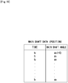
- any of the first through tenth configurations is characterized in that the sewing machine further comprises a storage section (92) that stores embroidery data including data pertaining to to a stitch length and a remaining length of the needle thread for each stitch, wherein the control section generates from the embroidery data, on a per-stitch basis, angle correspondence data which specify an angle of the needle thread motor representing a rotational position of the needle thread motor, for each angle of a main shaft motor representing a rotational position of the main shaft motor which rotates the main shaft for transmitting torque to the thread take-up lever; and the control section also controls, on the basis of the angle correspondence data, a position of the needle thread motor to an angle of the needle thread motor corresponding to the angle of the main shaft motor, as the angle of the main shaft motor changes as a result of rotation of the main shaft motor.”
- any one of the first through tenth configurations is characterized in that the sewing machine further comprises a storage section (92) that stores embroidery data including data pertaining to a stitch length and a remaining length of the needle thread for each stitch, wherein the control section generates data for circular movement arm for storing, on a per-stitch basis, data pertaining to an angle corresponding to a stitch reference length used in the first segment and also storing, on a per-stitch basis, data pertaining to angle data corresponding to a length determined by subtracting a remaining length of the needle thread from the stitch reference length used in the second segment; and the control section generates from the embroidery data and the data for circular movement arm, on a per-stitch basis, angle correspondence data which specify an angle of the needle thread motor representing a rotational position of the needle thread motor, for each angle of a main shaft motor representing a rotational position of the main shaft motor which rotates the main shaft for transmitting torque to the thread take-up lever; and the control section also controls, on the basis of the
- any one of the first through twelfth configurations is characterized in that the sewing machine further comprise a needle thread support member (88) that supports in a sideway direction a range on both sides of the first needle thread portion of the needle thread including the first needle thread, wherein a direction of a circulatory movement axis of the circular movement arm is a sideway direction; a first direction in the direction of circular movement of the circular movement arm is an upward direction of circular movement; and a second direction is a downward direction of circular movement.
- a needle thread support member (88) that supports in a sideway direction a range on both sides of the first needle thread portion of the needle thread including the first needle thread, wherein a direction of a circulatory movement axis of the circular movement arm is a sideway direction; a first direction in the direction of circular movement of the circular movement arm is an upward direction of circular movement; and a second direction is a downward direction of circular movement.
- a sewing machine comprises:
- the circular movement arm performs circular movement through an angle corresponding to the stitch reference length, which is a stitch length achieved when the n+1 th stitch is fixed by the needle thread fixing section in the first segment.
- the needle thread having the length required for the n+1 th stitch is prepared between the cloth and the circular movement arm.
- the second needle thread portion is fixed by the needle thread fixing section. Therefore, there is no risk of the shuttle withdrawing the needle thread from the stitch fixed by the needle thread fixing section (i.e., the n th stitch).
- the upstream grip section stays closed, and the downstream grip section stays open. Accordingly, there is no fear of the needle thread being withdrawn from an upstream position with respect to the upstream grip section.
- the thread take-up lever ascends in the second segment.
- the circular movement arm performs circular movement in the first direction, thus withdrawing the needle thread from the n th stitch.
- the remaining length of the needle thread of the n th stitch correspondingly becomes shorter.
- the needle thread is held fixed by the needle thread fixing section. Therefore, the needle thread becomes folded back at the position of the needle thread fixing section.
- the sewing machine of the present invention creates hollow embroidery by fixing needle thread with the thread hooking rod. Therefore, the plate-shaped member to be used for superposing the needle thread on the cloth to be embroidered is unnecessary with the needle thread fixing section, nor is required dissolution of the plate-shaped member. Moreover, the length of the needle thread can be controlled on a per-stitch basis by means of the angle of circular movement of the circular movement arm in the second segment. Therefore, there can be provided a sewing machine capable of creating elaborate hollow embroidery. The length of the needle thread (i.e., the remaining length of the needle thread) is made longer, thereby preventing excessive pulling of the cloth, which would otherwise be caused by making stitches, and the embroidered cloth does not become wavy (or uneven). Further, stitches can be made soft.
- the control section can also be embodied as follows. Specifically, “the control section (90) that controls the operation of the upstream drive section, the operation of the downstream drive section, the operation of the needle thread motor, and the operation of the needle thread fixing drive section (or can also be referred to as a "needle thread fixing section”); that, in the first segment which is at least the portion of a time segment from the top dead center of the shuttle to the bottom dead center of the shuttle, circularly moves the circular movement arm, by control of the needle thread motor, in the second direction through an angle corresponding to a stitch reference length which is a needle thread length of a stitch achieved while an n+1 th stitch next to a proximal n th stitch ("n" is an integer), among stitches already made in the cloth, is fixed to the needle thread fixing section; that, in the second segment which is at least a portion of a time segment from the bottom dead center of the shuttle to the top dead center of the shuttle, circularly moves the circular movement arm, by control of the needle
- control section can also be embodied as follows. Specifically, "a control section (90) that controls operation of the upstream drive section, operation of the downstream drive section, operation of the needle thread motor, and operation of the needle thread fixing drive section (or can also be called a “needle thread fixing section”) ; that, in the first segment which is at least a portion of a segment from the top dead center of the shuttle to the bottom dead center of the shuttle, circularly moves the circular movement arm, by control of the needle thread motor, in the second direction through an angle corresponding to a stitch reference length which is a needle thread length of a stitch achieved while the n+1 th stitch next to the proximal n th stitch ("n" is an integer), among the stitches already made in the cloth, is fixed to the needle thread fixing section; that, in the second segment which is at least a portion of the segment from the bottom dead center of the shuttle to the top dead center of the shuttle, circularly moves the circular movement arm, by control of the needle thread motor, in the first direction through
- the control section in relation to the fourteenth configuration, the control section generates data for circular movement arm for storing, on a per-stitch basis, data pertaining to an angle corresponding to a stitch reference length used in the first segment and also storing, on a per-stitch basis, data pertaining to angle data corresponding to a length determined by subtracting a remaining length of the needle thread from the stitch reference length used in the second segment; and generates angle correspondence data from the embroidery data and the data for circular movement arm.
- the control section circularly moves the circular movement arm in the first direction through an angle that is obtained by subtracting the angle corresponding to the remaining length of the needle thread which is a length of the needle thread projecting out of the cloth surface in the n th stitch, from an angle corresponding to the stitch reference length in the n th stitch, instead of circularly moving the circular movement arm in the first direction through an angle corresponding to a length which is obtained by subtracting the remaining length of the needle thread, which is the length of the needle thread projecting out of the cloth surface in the n th stitch, from the stitch reference length in the n th stitch.
- a sewing machine based on the present invention creates hollow embroidery by fixing a needle thread with the needle thread fixing section. Therefore, the plate-shaped member to be used for superposing the needle thread on the cloth to be embroidered is unnecessary, nor is required dissolution of the plate-shaped member. Moreover, the length of the needle thread (in other words, a remaining length of the needle thread) can be controlled on a per-stitch basis by means of the angle of circular movement of the circular movement arm in the second segment. Therefore, there can be provided a sewing machine capable of creating elaborate hollow embroidery.
- the length of the needle thread (i.e., the remaining length of the needle thread) is made longer, thereby preventing excessive pulling of the cloth, which would otherwise be caused by making stitches, and the embroidered cloth does not become wavy (or uneven). Further, stitches can be made soft.
- an object of providing a sewing machine which needs neither a plate-shaped member to be superposed on a cloth to be embroidered nor dissolution of the plate-shaped member and which is also capable of adjusting the length of a needle thread on a per-stitch basis and obtaining elaborate hollow embroidery, is accomplished as will be stated below.
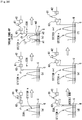
- a sewing machine 5 of an embodiment is an embroidery sewing machine and configured as illustrated in Figure 1 to Figure 14 .
- the sewing machine has a head (an embroidery head) 7, a shuttle 12d, a sewing frame 12e, a frame actuator 24, a storage device 92.
- the head 7 is positioned above an approximately-flat-plate-shaped sewing machine table 3.
- a frame 120 stands upright on an upper surface of the sewing machine table.
- the head 7 is disposed on a front side of the frame 120.
- the sewing machine table 3 also assumes the shape of an approximately-flat plate and, as illustrated in Figure 6 , has a plate-shaped table body 4 and a throat plate 5 placed in an opening formed in the table body 4.
- a pinhole 5a is formed in the throat plate 5.
- the head 7 is configured as illustrated in Figure 1 through Figure 11 and has a mechanical element group 10, a main shaft motor 20, a main shaft 22, an upstream grip section 40, a downstream grip section 60, a circular movement section 80, a needle thread support member 88, a control circuit 90, needle thread guides 104 and 106, and a case 110.
- a needle thread control section is made up of the upstream grip section 40 and the downstream grip section 60.
- the machine element group 10 includes respective machine elements to be actuated in the head 7, and the machine elements include a thread take-up lever 12a, a needle bar 12b, and a presser foot 12c.
- the thread take-up lever 12a and the needle bar 12b are actuated by transmitting torque of the main shaft 22 by way of power transmission means, such as a cam mechanism and a belt mechanism.
- the thread take-up lever 12a is disposed in the case 110 and formed so as to be swayable around an axis (a rotation center) extending in a horizontal direction (an X1-X2 direction), thus circularly moving between the bottom dead center (one dead center) and the top dead center (the other dead center) .
- the thread take-up lever 12a is pivotally supported by the case 110 so as to be swayable around a rotation center (which can also be taken as a pivot) 12ab.
- a needle thread inserted into a sewing needle 12ba is inserted into the thread take-up lever 12a.
- a leading end of the thread take-up lever 12a projects to the front (Y1 side) out of an opening 116d formed in a front section 110-1 of the case 110, thus being exposed.
- a tension spring 102 that can also be referred to as a “thread take-up spring” (generally called a “high tension spring”)] that guides a needle thread J sent from an upstream position (i.e., from the downstream grip section 60) while eliminating flexure or a slack in the needle thread J is fixedly mounted at a position on the front section 110-1 of the case 110 in a neighborhood of a lower portion of the opening 116d.
- the tension spring 102 inverts the needle thread J guided from the upper position and subsequently guides the needle thread to the thread take-up lever, and tension is exerted on the needle thread J by the tension spring 102.
- a rod-shaped guide member can also be used in place of the tension spring 102.
- the needle bar 12b is provided so as to be movable in the vertical direction with reference to the case 110.
- the sewing needle 12ba (the needle thread is inserted into a pin hole 12bb of the sewing needle 12ba) is fixedly provided at a lower end of the needle bar 12b.
- a needle bar connecting stud 14a is fixedly provided at an approximately intermediate position on the needle bar 12b in the vertical direction.
- a base needle bar 14c is disposed in the vertical direction in the case 110.
- the base needle bar 14c is equipped with a needle bar up-down member 14b (or can also be referred to as a "needle bar up-down actuation component" or a “needle bar elevation element") which is to engage with a needle bar connecting stud 14a, so as to be vertically movable along the base needle bar 14c.
- the needle bar up-down member 14b is vertically moved by use of a mechanism for vertically moving the needle bar up-down member 14b, whereby the needle bar connecting stud 14a is vertically actuated, and the needle bar 12b is also vertically moved.
- An up-down actuation mechanism 14 serving as a mechanism for actuating the needle bar 12b up and down has the needle bar connecting stud 14a, the needle bar up-down member 14b, and a crank rod 14d for actuating the needle bar up-down member 14b up and down.
- a transmission mechanism (not shown) for transmitting torque of the main shaft 22 is joined to the crank rod 14d.
- the crank rod 14d also rotates, and the needle bar up-down member 14b thereby moves up and down along the base needle bar 14c.
- the needle bar 12b reciprocally moves in the vertical direction.
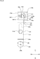
- the presser foot 12c is provided at a bottom side of the case 110 so as to be movable up and down with respect to the case 110, and also has a thread hooking rod 236 (which can also be a "rod-shaped member") for hooking the needle thread in a sideway direction.
- the presser foot 12c has a main body 210, a swayingly reciprocating mechanism section (which can also be taken as a “rotating mechanism section” or a “swiveling mechanism section”) 230 which swayingly performs reciprocation with respect to the main body 210, a thread hooking rod drive motor (an actuation section for fixing a needle thread) 240 for actuating the swayingly reciprocating mechanism section 230.
- Figure 8 is a cross-sectional view taken along line A-A shown in Figure 6
- Figure 9 is a cross-sectional view taken along line B-B shown in Figure 6 .
- Figure 9 shows a cutting position as being shifted on its way.
- the main body (a presser foot main body) 210 has a base 212 and a shaft 220 fixed to the base 212.
- the base 212 has a main body structure section (which can also be taken as a "central configuration section") 214 assuming the shape of a quadrate (specifically, a "rectangular shape”) plate; a leading-end structure section (which can also be taken as a “leading end section”) (a “cloth surface contact section”) 216 continued from a front-side end (one of a pair of short sides) of the main body structure section 214, a needle thread receiving section 216f attached to an interior surface of a vertical plate 216e of the leading-end structure section 216, and a base end 218 continued from a rear-side end (a remaining one of the pair of the short sides).
- the leading-end structure section 216 is equivalent to "the cloth surface contact section which contacts a cloth surface when the presser foot is situated at a cloth surface contact position.”
- the main body structure section 214 is provided with a through hole 214a, and the shaft 215 is provided in the through hole 214a.
- the shaft 215 has a head 215a whose diameter is larger than that of the through hole 214a, a shaft main body 215b continued from the head 215a and inserted into the through hole 214a, and a retaining section 215c fixed to an end of the shaft main body 215b opposite the head 215a.
- the shaft 215 is fixed to the main body structure section 214 and inserted into the main body structure section 214 so as not to be able to move with respect to the main body structure section 214 in a direction perpendicular to an axis of the shaft 215.
- the main body structure section 214 opposes a thread hooking rod support 231 (particularly a sideway plate 232).
- the shaft 215 is configured so as to rotate around the axis of the shaft 215 with respect to the main body structure section 214, the head 215a of the shaft 215 can also be configured so as to become fixed to the main configuration 214.
- the leading-end structure section 216 has a sidewise-elongated quadrate vertical plate 216a continued downwardly from a front-side end of the main body structure section 214, a sideway plate 216b continued from a front-side end to a front side of the vertical plate 216a, a vertical plate 216c continued downward from a front-side end of the sideway plate 216b, a sidewise-elongated rectangular sideway plate 216d continued from a lower end of the vertical plate 216c to the rear side, and a vertical plate 216e (see Figure 8 and Figure 9 ) formed at right angles to the sideway plate 216b and the sideway plate 216d between a right-side end of the sideway plate 216b and a right-side end of the sideway plate 216d.
- the vertical plate 216a forms a right angle with respect to the main body structure section 214 and the sideway plate 216b
- the vertical plate 216c forms a right angle with respect to the sideway plate 216b and the
- the sideway plate 216b and the sideway plate 216d assume the shape of a quadrate (specifically a "rectangular shape") plate and are formed parallel to each other.
- a circular opening 216bk is formed in the sideway plate 216b, and a circular opening 216dk is formed in the sideway plate 216d.
- the opening 216bk and the opening 216dk are holes for insertion of the needle thread and the sewing needle 12ba.
- the opening 216bk and the opening 216dk are formed so as to have the same diameter (which can also be said to be substantially the same), and the opening 216bk and the opening 216dk are placed at the same position in the horizontal direction (in other words, a direction other than the vertical direction) .
- the openings 216bk and 216dk are inserted portions for insertion of the sewing needle.
- the sideway plate 216b and the sideway plate 216d are formed to have the same size and the same shape.
- a spacing h1 (see Figure 6 ) between the sideway plate 216b and the sideway plate 216d is made larger than a diameter of the thread hooking rod 236 so as to enable the thread hooking rod 236 to be able to swivel at a position between the sideway plate 216b and the sideway plate 216d.
- the thread hooking rod 236 presses the needle thread while a lower surface of the sideway plate 216d of the leading-end structure section 216 remains in contact with the cloth. Accordingly, spacing exists between height of an upper surface of the cloth and height of the thread hooking rod 236.
- a spacing h2 exists between a lower surface of the sideway plate 216d and an upper end of the thread hooking rod 236.
- the thread hooking rod 236 thereby fixes the needle thread at a position apart from the surface of the cloth.
- the spacing h2 is a height of the thread hooking rod in Equation 1 provided below.
- a length of the sideway plate 216b and a length of the sideway plate 216d achieved in a right-left direction are made longer than a length of the main body structure section 214 achieved in the right-left direction.
- Positions of sides on right-side surfaces of the sideway plates 216b and 216d achieved in the right-left direction coincide with position of side on the right-side surface of the main body structure section 214 achieved in the right-left direction (side of the right-side surface of the sideway plate 216b and side of the right-side surface of the main body structure section 214 are in line when viewed from the above).
- the sideway plates 216b and 216d are formed so as to project to the left-side direction with respect to the left-side surface of the main body structure section 214.
- the needle thread receiving section 216f has an elastic section 216f-1 provided on an interior surface of the vertical plate 216e and a plate-shaped section (a needle thread receiving main body) 216f-2 fixed to an end of the elastic section 216f-1 opposite to the vertical plate 216e.
- the elastic section 216f-1 is a coil spring that is fixed at one end thereof to the vertical plate 216e and at the other end to the plate-shaped section 216f-2.
- the plate-shaped section 216f-2 is formed from; for instance, metal or a synthetic resin.
- the needle thread receiving section 216f is for fixedly pinching the needle thread together with the thread hooking rod 236.
- an axis line (a center line) of the coil spring making up the elastic section 216f-1 is formed in the right-left direction (the X1-X2 direction).
- An extension of the axis of the coil spring is formed so as to pass through a center (or its neighborhood) of the opening 216bk and the opening 216dk.
- the elastic section 216f-1 is for forcing the thread hooking rod 236 having swiveled, substantially toward the left-side surface (in X1 direction), and at least the elastic section 216f-1 forces the thread hooking rod 236 having swiveled, in the sideway direction.
- the elastic section 216f-1 since the elastic section 216f-1 is provided, the orientation of the plate-shaped section 216f-2 becomes variable.
- the needle thread i.e., a second needle thread portion Jb (see Figure 20 )
- the needle thread can be pinched by means of the thread hooking rod 236 and the plate-shaped section 216f-2.
- the needle thread receiving section 216f has the same structure as the needle thread receiving section 214c of the needle thread fixing unit 12f shown in Figure 30
- the plate-shaped section 216f-2 has the same structure as the plate-shaped section 214c-2 of the plate-shaped section 214c-2 shown in Figure 30 .
- the needle thread receiving section 216f is placed at a position deviating toward the cloth surface with respect to the position of insertion of the sewing thread 12ba (i.e., a position deviating toward X2).
- the thread hooking rod 236 fixes the needle thread at a position apart from the cloth surface (i.e., the upper surface of the cloth).
- the swayingly reciprocating mechanism section 230 (particularly, the thread hooking rod 236) and the needle thread receiving section 216f in the main body 210 fix a second needle thread portion, which is a portion of the needle thread located between the cloth and the thread take-up lever, at a position deviating from the position of insertion of the sewing needle toward the upper surface of the cloth as well as at a position higher than the upper surface of the cloth.
- the swayingly reciprocating mechanism section 230 (particularly, the thread hooking rod support 231 and the thread hooking rod 236) and the needle thread receiving section 216f of the main body 210 make up "a needle thread fixing section that fixes a second needle thread portion of the needle thread situated between a cloth and the thread take-up lever at a position apart from a cloth surface and at a position deviating toward the cloth surface from a position where the sewing needle is to be inserted.”
- the needle thread receiving section 216f Since the needle thread receiving section 216f is placed at the position deviating from the position of insertion of the sewing needle 12ba toward the cloth surface, the needle thread comes to straddle the thread hooking rod 236 (i.e., the needle thread is folded back at the position of the thread hooking rod 236) when the sewing needle 12ba is inserted into the cloth while the needle thread is pressed by the thread hooking rod 236 and the needle thread receiving section 216f.
- the opening 216bk and the opening 216dk are not limited to the circular shape, and cutouts can also be used in lieu of the opening 216bk and the opening 216dk.
- the opening 216bk is formed to the leading end of the sideway plate 216b
- the opening 216dk is formed to the leading end of the sideway plate 216d.
- an opening is formed in the vertical plate 216c so as to interconnect the opening 216bk and the opening 216dk.
- a cutout extending from the sideway plate 216bk up to the sideway plate 216dk via the vertical plate 216c is thus formed.
- the base end 218 has a sidewise-elongated rectangular vertical plate 218a continued upwardly from a rear-side end of the main body structure section 214 and a sideway plate 218b continued from an upper end of the vertical plate 218a to the rear side.
- the vertical plate 218a forms a right angle with respect to the main body structure section 214
- the sideway plate 218b forms a right angle with respect to the vertical plate 218a.
- a right-left length of the vertical plate 218a and a right-left length of the sideway plate 218b are made substantially the same, and the right-left length of the vertical plate 218a and the right-left length of the sideway plate 218b are made substantially identical with a right-left length of the main body structure section 214.
- a shaft 220 is fixed at an end position on a front-side upper surface of the sideway plate 218b of the base end 218, and stands upright with respect to the upper surface of the sideway plate 218b.
- the structure of the base 212 exclusive of the needle thread receiving section 216f makes up a needle thread fixing section main body 212-1 that supports the needle thread receiving section 216f.
- the swayingly reciprocating mechanism section 230 has the sideway plate 232 supported by the shaft 215, a vertical plate 234 continued downward from a front-side end of the sideway plate 232, the thread hooking rod 236 fixed to the vertical plate 234, and a rotary disc 238 rotatably attached to the sideway plate 232.
- the sideway plate 232 assumes a strip shape, or the shape of a strip whose upper surface assumes the shape of a combination of one short side of a rectangular shape with a semicircular shape.
- a width of the sideway plate 232 in the direction of its shortness is substantially identical with a shorter width of the main body structure section 214.
- an opening 232k elongated in the front-back direction is formed in the sideway plate 232.
- the shaft man body 215b of the shaft 215 is inserted into the opening 232k.
- the shaft main body 215b becomes slidable relatively with respect to the sideway plate 232 in a lengthwise direction of the opening 232K.
- the vertical plate 234 is a rectangular plate and forms a right angle with respect to the sideway plate 232.
- a right-side end of the vertical plate 234 and a right-side end of the sideway plate 232 coincide with each other in the right-left direction.
- the vertical plate 234 projects in excess of the sideway plate 232 in the left-side direction, so that an left-side end of the vertical plate 234 is situated further leftward in excess of a left-side end of the sideway plate 232.
- a hole for insertion of the thread hooking rod 236 is formed in the vertical plate 234.
- the sideway plate 232 and the vertical plate 234 make up the thread hooking rod support (which can also be taken as the "swayingly reciprocating mechanism section") 231.
- the thread hooking rod 236 has a columnar thread hooking rod main body 236a and a head 236b which is provided at an end of the thread hooking rod main body 236a and larger in diameter than the thread hooking rod main body 236a.
- the thread hooking rod 236 is fixed to the vertical plate 234 by inserting the thread hooking rod main body 236a into the hole of the vertical plate 234.
- the thread hooking rod 236 is made of; for instance, metal.
- a conceivable method for fixing the thread hooking rod 236 to the vertical plate 234 is to cut a screw thread in a portion of the thread hooking rod main body 236a facing a head 236b , to cut a screw thread in the hole of the vertical plate 234, and to screw-engage the thread hooking rod main body 236a in the vertical plate 234.
- the rotary disc 238 assumes the shape of a circular plate, and an output shaft 242a is fixed to a center position of the rotary disc 238.
- the rotary disc 238 and the sideway plate 232 are connected to each other at a position apart from the output shaft 242a of a thread hooking rod drive motor 240 (i.e., a position eccentric from the rotation center of the rotary disc 238).
- a through hole for insertion of a shaft 239 is made at a position eccentric from the rotation center of the rotary disc 238.
- a through hole for insertion of the shaft 239 is formed at a center of an end region in the right-left direction on the rear-side of the sideway plate 232.
- the rotary disc 238 and the sideway plate 232 are connected by inserting the shaft 239 into the respective through holes.
- the shaft 239 has a head 239a which is larger in diameter than the through hole of the rotary disc 238, a shaft main body 239b which continually extends from the head 239a and is inserted into each of the through holes, and a retaining section 239c fixed to an end of the shaft main body 239b opposite to the head 239a.
- the thread hooking rod drive motor 240 is fixed to the base 212 (specifically a sideway plate 218b of the base end 18) .
- An output shaft 240a of the thread hooking rod drive motor 240 is perpendicular to an upper surface of the sideway plate 232, and the output shaft 240a is perpendicular to a pair of upper and lower planes of the rotary disc 238, so that the rotary disc 238 and the sideway plate 232 are formed in parallel with each other.
- the rotary disc 238 rotates when the thread hooking rod drive motor 240 is driven.
- the rear side of the sideway plate 232 rotates as a result of rotation of the rotary disc 238.
- the sideway plate 232 moves to and fro in a front-back direction (a second horizontal direction) while swaying in the right-left direction (a first horizontal direction) because the shaft main body 215b is inserted into the opening 232k.
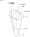
- the thread hooking rod 236 also moves to and fro in the same manner while swaying in the right-left direction, whereupon the thread hooking rod 236 swivels along a sideway surface (plane) (which can also be taken as a horizontal (or substantially horizontal) surface (plane)) (in other words, the thread hooking rod 236 swivels along a plane parallel (substantially parallel) to the cloth surface).
- plane sideway surface
- plane which can also be taken as a horizontal (or substantially horizontal) surface (plane)
- the thread hooking rod 236 can also be said to swivel along a surface (plane) that is at a right angle (which can also be substantially right angels) to the direction of the second needle thread portion (which can also be a direction of ranges on both sides of the second needle thread) (the vertical direction).
- a leading end 236Q of the thread hooking rod 236 swivels along a sideway direction (which can also be a "horizontal direction"), thereby forming a substantially elliptical locus when viewed from above as shown in Figure 10 .
- a locus of a point of intersection 236P between the thread hooking rod main body 236a and an axis 236g (a widthwise center line) on a front-side side portion of the vertical plate 234 forms a pattern, such as that illustrated in Figure 10 .
- the swayingly reciprocating mechanism section 230 reciprocally moves in the front-back direction by the crank mechanism while swaying in the right-left direction with respect to the main body structure section 214 of the base 212.
- the crank mechanism can be said to be made up of the rotary disc 238, the sideway plate 232 connected to the rotary disc 238 at a position eccentric from its rotation center, and the shaft 215.
- the locus of the leading end 236Q of the thread hooking rod 236 is situated outside a brim of the opening 216bk and a brim of the opening 216dk when viewed from above.
- the structure of the swayingly reciprocating mechanism section 230 e.g., the length of the swayingly reciprocating mechanism section 230 in its lengthwise direction, the length of the thread hooking rod 236, a position of attachment of the thread hooking rod 236, and a length of deviation of the rotary disc 238 (a length between the center of the output shaft 240a and the center of the axis 239)
- the thread hooking rod 236 may not hook the needle thread.
- the presser foot 12c is actuated up and down by an up-down actuation mechanism 250.
- the up-down actuation mechanism 250 has a fixed component 252 fixed to the shaft 220, a shaft 254 fixed to the case 110, a presser foot up-down component 256 formed so as to be movable up and down along the shaft 254, and a crank rod 258.
- the fixed component 252 is formed similarly to the needle bar connecting stud 14a, and the shaft 254 is placed at a right angle to a bottom section 110-3 of the case 110 and formed in a perpendicular direction.
- the presser foot up-down component 256 is in engagement with the fixed component 252.
- a transmission mechanism (not shown) for transmitting torque of the main shaft 22 is joined to the crank rod 258. When the main shaft 22 rotates, the crank rod 258 also rotates, whereby the presser foot component 256 moves up and down along the shaft 254. Thus, the presser foot 12c reciprocally moves in the vertical direction.
- the presser foot 12c moves (or can also move to and fro) between the bottom dead center (a cloth surface contact position) where a contact with the cloth surface is achieved and the top dead center (a position apart from the cloth surface) apart from the cloth surface.
- the presser foot 12c is situated at the bottom dead center in a segment of a predetermined range.
- a start position of a bottom dead center segment is located at an arbitrary position between a position where the frame actuator 24 has stopped and a position where the sewing needle 12ba is inserted into the cloth (a position of about 100 degrees in Figure 19 ).
- An end position of the bottom dead center segment is located at an arbitrary position between a position where the sewing needle 12ba comes out of the cloth as a result of elevation of the sewing needle 12ba (a position where the sewing needle 12ba is released from its inserted state) and a position where the frame actuator 24 operates (a position of about 250 degrees in Figure 19 ).
- the frame actuator 24 when the frame actuator 24 is in the middle of operating, the cloth cannot be pressed. Further, when the sewing needle 12ba is inserted into the cloth, the cloth must be pressed.
- the starting position of the bottom dead center segment is set as mentioned above.
- the sewing needle 12ba is in the middle of being inserted in the cloth, the cloth must be pressed.
- the presser foot 12c ascends from the end position of the bottom dead center segment, comes to the top dead center at a position of about 340 degrees, subsequently maintains the top dead center up to the position of about 10 degrees, and subsequently starts descending.
- the shuttle 12d is placed at a position that is beneath the head 7 and lower than an upper surface of the sewing machine table. Specifically, the shuttle 12d is supported, below the pinhole 5a of the throat plate 5, by a shuttle base (not shown) disposed below the sewing machine table. A bobbin is accommodated in the shuttle 12d, and a bobbin thread is wound around the bobbin.
- the shuttle 12d rotates when receiving the torque of the main shaft 22 being transmitted, and a point 12d-1 (see Figure 1 ) provided on the shuttle 12d hooks the needle thread.
- the shuttle 12d thereby captures and draws the needle thread, entwines the needle thread with the bobbin thread, thereby making stitches.
- the shuttle 12d is actuated by transmitting the torque of the main shaft 22 by way of the power transmission means, such as a cam mechanism and a belt mechanism.
- the sewing frame 12e is a member for holding a cloth (specifically, a cloth to be embroidered) under tension and placed at an elevated position above (or an upper surface of) the sewing machine table.
- the main shaft 22 is rotated by the main shaft motor 20, and torque of the main shaft 22 is transmitted by a predetermined power transmission mechanism, whereby respective machine elements, such as the thread take-up lever 12a, the needle bar 12b, and the presser foot 12c, and the shuttle 12d are actuated.
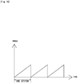
- the main shaft motor 20 is configured so as to rotate in one direction.
- the frame actuator 24 is for moving the sewing frame 12e in an X-axis direction (the direction X1-X2) and a Y-axis direction (the direction Y1-Y2) in response to a command from the control circuit 90.
- the sewing frame 12e is moved in synchronization with up-down movements of the needle bar 12b.
- the frame actuator 24 is specifically made up of a servo motor for moving the sewing frame 12e in the X-axis direction, a servo motor for moving the sewing frame 12e in the Y-axis motor, and others.
- the upstream grip section 40 is placed at an upstream position in the head 7; in other words, above the circular movement section 80, and has a grip section main body (upstream grip section main body) 41 and a magnet section (an upstream drive section, or an upstream magnet section) 50 provided on a rear side of the grip section main body 41.
- the grip section main body 41 has a first plate-shaped section unit 42 and a second plate-shaped section (an upstream second plate-shaped section) 44 provided at the rear side of the first plate-shaped section 42a of the first plate-shaped section 42 and on the front side of the front section 110-1 of the case 110.
- the first plate-shaped section unit 42 has a first plate-shaped section (an upstream first plate-shaped section) 42a assuming the shape of a quadrate plate and a hooking section (attachment member) 42b formed so as to protrude from an upper end of the first plate-shaped section 42a toward the rear.
- the hooking section 42b assumes the shape of an approximately-L-shaped plate (a shape defined by bending a rectangular plate into an approximately-L-shaped fold).
- the first plate-shaped section unit 42 is integrally formed from a magnet-attractive material (a material to which a magnet adheres); namely, a magnetic substance (which can also be a ferromagnetic substance) .
- the first plate-shaped section unit 42 is made up of; for instance, metal attracted by a magnet, such as iron.
- the first plate-shaped section 42a hangs (or can also dangle) from the front section 110-1 as a result of the hooking section 42b being hooked by a hooking hole 110a formed in the front section 110-1 of the case 110.
- the first plate-shaped section 42a thereby performs sliding movement in the vertical direction with respect to the front-side surface of the second plate-shaped section 44, whereby a spacing between the first plate-shaped section 42a and the second plate-shaped section 44 becomes variable.
- the second plate-shaped section 44 is one plate-shaped member provided on the rear side of the first plate-shaped section 42a in the first plate-shaped section unit 42, and assumes the shape of an elongated rectangular shape. Specifically, the second plate-shaped section 44 is formed so as to become longer than the length of the first plate-shaped section 42a in the right-left direction and become approximately identical in length with (in a rigorous sense, slightly shorter than) the first plate-shaped section 42a in the up-down direction. A left end of the second plate-shaped section 44 when viewed from front is situated further leftward than a side of the left side surface of the first plate-shaped section 42a, and fixed to the front section 110-1 by a presser plate 46.
- a right end of the second plate-shaped section 44 when viewed from front is situated further rightward than a side of the right side surface of the first plate-shaped section 42a, and fixed to the front section 110-1 by the presser plate 46.
- the second plate-shaped section 44 is present in parallel to the first plate-shaped section 42a at the rear of the first plate-shaped section unit 42a.
- the second plate-shaped section 44 is formed from a magnet-unattractive material (a material to which a magnet does not adhere); in other words, a non-magnetic substance; for instance, a synthetic resin film.
- the second plate-shaped section 44 can also be formed from aluminum or stainless steel.
- An sidewise-elongated rectangular opening (a second opening) 116a is formed in an upper portion of the front section 110-1 of the case 110, and the second plate-shaped section 44 is provided so as to cover the opening 116a from the front.
- the opening 116a is formed smaller than the second plate-shaped section 44, and the vertical height of the second plate-shaped section 44 is made larger than a leading end of the magnet section 50 in such a way that the leading end of the magnet section 50 can pass through the opening 116a.
- the hooking hole 110a for hooking the hooking section 42b of the first plate-shaped section unit 42 is formed at a position above the opening 116a on the front section 110-1.
- the hooking hole 110a is formed so as to penetrate through the front section 110-1.
- the magnet section 50 is made of an electromagnet, and the leading end of the magnet section 50 is situated in the opening 116a and formed so as to contact a rear-side surface of the second plate-shaped section 44. A leading-end surface of the magnet section 50 (a surface facing the second plate-shaped section 44) serves as an attracting surface.
- the magnet section 50 assumes the shape of a substantially square pole (the same also applies to a magnet section 70). Incidentally, the magnets 50, 70 have the same structure as that of an ordinary electromagnet.
- the magnet has a core made of a magnetic material and a coil wound around the core, and magnetic forces develop as a result of energization of the coil.
- One magnet section 50 is provided in the upstream grip section 40.
- the control circuit 90 activates the magnet section 50, whereby the first plate-shaped section 42a is attracted by the magnetic force. Thus, clearance between the first plate-shaped section 42a and the second plate-shaped section 44 becomes closed.
- the magnet section 50 is supported by a support 112a of the case 110.
- rod-shaped guide members (first guide members) 52 and 54 are provided above and below the first plate-shaped unit section 42 when viewed from front.
- the guide members 52 and 54 are fixed to the front-side 110-1 of the case 110.
- the guide members 52 and 54 are placed such that the needle thread J diagonally passes by the rear-side of the first plate-shaped section.
- the guide member 52 is provided at the left side above the first plate-shaped section 42a when viewed from front
- the guide member 54 is provided at the right side below a lower portion of the first plate-shaped section 42a when viewed from front.
- a path for the needle thread J laid on the rear-side of the first plate-shaped section 42a can thereby be made longer, so that the needle thread J can be more reliably gripped between the first plate-shaped section 42a and the second plate-shaped section 44.
- the downstream grip section 60 is placed at an approximately intermediate position on the head 7 in the up-down direction; namely, below the circular movement section 80, and has a grip section main body (a downstream grip section main body) 61 and a magnet section (a downstream drive section or a downstream magnet section) 70 provided on a rear-side of the grip section main body 61.
- the grip section main body 61 has the same structure as that of the grip section main body 41; namely, has a first plate-shaped section unit 62 and a second plate-shaped section (a downstream second plate-shaped section) 64 provided at the rear side of the first plate-shaped section 62a of the first plate-shaped section 62 and on the front side of the front section 110-1 of the case 110.
- the first plate-shaped section unit 62 has a first plate-shaped section (a downstream first plate-shaped section) 62a assuming the shape of a quadrate plate and a hooking section (attachment member) 62b formed so as to protrude from an upper end of the first plate-shaped section 62a toward the rear.
- the hooking section 62b assumes the shape of an approximately-L-shaped plate (a shape defined by bending a rectangular plate into an approximately-L-shaped fold).
- the first plate-shaped section unit 62 is integrally formed from a magnet-attractive material (a material to which a magnet adheres); namely, a magnetic substance (which can also be a ferromagnetic substance).
- the first plate-shaped section unit 62 is made up of; for instance, metal attracted by a magnet, such as iron.
- the first plate-shaped section 62a hangs (or can also dangle) from the front section 110-1 as a result of the hooking section 62b being hooked by a hooking hole 110b formed in the front section 110-1 of the case 110.
- the first plate-shaped section 62a thereby performs sliding movement in the vertical direction with respect to the front-side surface of the second plate-shaped section 64, whereby a spacing between the first plate-shaped section 62a and the second plate-shaped section 64 becomes variable.
- the second plate-shaped section 64 has the same structure as that of the second plate-shaped section 44, and is one plate-shaped member provided on the rear side of the first plate-shaped section 62a in the first plate-shaped section unit 62 and assumes the shape of an elongated rectangular shape. Specifically, the second plate-shaped section 64 is formed so as to become longer than the length of the first plate-shaped section 62a in the right-left direction and become approximately identical in length with (in a rigorous sense, slightly shorter than) the first plate-shaped section 62a in the up-down direction.
- a left end of the second plate-shaped section 64 when viewed from front is situated further leftward than a side of the left side surface of the first plate-shaped section 62a, and fixed to the front section 110-1 by a presser plate 66.
- a right end of the second plate-shaped section 44 when viewed from front is situated further rightward than a side of the right side surface of the first plate-shaped section 62a, and fixed to the front section 110-1 by the presser plate 66.
- the second plate-shaped section 64 is present in parallel to the first plate-shaped section 62a at the rear of the first plate-shaped section 62a of the first plate-shaped section unit 62.
- the second plate-shaped section 64 is formed from a magnet-unattractive material (a material to which a magnet does not adhere); namely, a non-magnetic substance; for instance, a synthetic resin film.
- the second plate-shaped section 64 can also be formed from aluminum or stainless steel.
- a sidewise-elongated rectangular opening (a third opening) 116c is formed at an approximately-center portion of the front section 110-1 of the case 110 in its vertical direction, and the second plate-shaped section 64 is provided so as to cover the opening 116c from the front.
- the opening 116c is formed smaller than the second plate-shaped section 64, and the vertical width of the second plate-shaped section 64 is made larger than a leading end of the magnet section 70 in such a way that the leading end of the magnet section 70 can pass through the opening 116c.
- the hooking hole 110b for hooking the hooking section 62b of the first plate-shaped section unit 62 is formed at a position above the opening 116c on the front section 110-1.
- the hooking hole 110b is formed so as to penetrate through the front section 110-1.
- the magnet section 70 is made of an electromagnet such that the leading end of the magnet section 70 is situated in the opening 116c and contacts a rear-side surface of the second plate-shaped section 64.
- a leading-end surface of the magnet section 70 (a surface facing the second plate-shaped section 64) serves as an attracting surface.
- the magnet section 70 assumes the shape of a substantially square pole and is formed into (or approximately) the same size and shape as those of the magnet section 50.
- One magnet section 70 is placed in the downstream grip section 60.
- the control circuit 90 activates the magnet section 70, whereby the first plate-shaped section 62a is attracted by the magnetic force. Thus, clearance between the first plate-shaped section 62a and the second plate-shaped section 64 becomes closed.
- the magnet section 70 is supported by the support 112b of the case 110.
- rod-shaped guide members (first guide members) 72 and 74 are provided above and below the first plate-shaped unit 62 when viewed from front. Specifically, the guide members 72 and 74 are fixed to the front-side section 110-1 of the case 110. The guide members 72 and 74 are placed such that the needle thread J diagonally passes by the rear-side of the first plate-shaped section.
- the guide member 72 is provided at the left side above an upper portion of the first plate-shaped section 62a when viewed from front, and the guide member 74 is provided at the right side below a lower portion of the first plate-shaped section 62a when viewed from front.
- a path for the needle thread J laid on the rear-side of the first plate-shaped section 62a can thereby be made longer, so that the needle thread J can be more reliably gripped between the first plate-shaped section 62a and the second plate-shaped section 64.
- the circular movement section 80 is placed at an approximately intermediate position in the up-down direction between the upstream grip section 40 and the downstream grip section 60. Namely, the circular movement section 80 is placed at a downstream position with respect to the upstream grip section 40 and an upstream position with respect to the downstream grip section 60 in the direction feeding the needle thread.
- the circular movement section 80 is for circularly moving the needle thread between the grip section main body 41 and the grip section main body 61 (which can also be called a portion (position) of the needle thread situated between the grip section main body 41 and the grip section main body 61) .
- the circular movement section 80 has a circular movement arm 81 and a needle thread motor 86 that rotates the circular movement arm 81.
- the circular movement arm 81 has a rod-shaped main body section 82 and a hook 84 provided at one leading end of the main body section 82.
- An output shaft of the needle thread motor 86 is secured to the other end of the main body section 82.
- the hook 84 assumes the shape of an approximately U-shaped plate and is formed in such a way that the hook 84 can hook (or also "lock") by circular movement of the circular movement arm 81. More specifically, the hook 84 has a groove 84a provided in parallel with an axis of the output shaft of the needle thread motor 86.
- the hook 84 is arranged so as to be able to contact and retain the needle thread J laid in parallel with the axis line of the output shaft of the needle thread motor 86 as a result of the circular movement arm 81 being circularly moved upward around the output shaft (the rotation center) of the needle thread motor 86.
- the circular movement arm 81 is interposed between the magnet section 50 and the magnet section 70 and arranged so as to be able to hook the needle thread.
- a portion hooked (or locked) and circularly moved by the circular movement arm 81 is a first needle thread portion Ja.
- an encircled drawing in Figure 5 illustrates a structure of only the circular movement arm 81 for ease of comprehension.
- the needle thread motor 86 is secured to a support 112c of the case 110.
- the axis of the output shaft of the needle thread motor 86 is oriented in the right-left direction.
- a lower limit position (a position designated by 81 (B) in Figure 3 and Figure 4 ) (a second end position at an end in the second direction) achieved in the range of circular movement of the circular movement arm 81 corresponds to a state where the needle thread is in contact with the groove 84a of the hook 84 of the circular movement arm 81 when the needle thread is linearly supported by the pair of needle thread support members 88 in a sideway direction (in other words, when the needle thread is supported in a sideway direction by the connection members 88c of the pair of needle thread support members 88) [more specifically, the position where the connection members 88c of the pair of needle thread support members 88 receive the needle thread is at the (or approximately) same level as the position where the groove 84a of the hook 84 receives the needle thread, and the needle thread is in contact with the pair of needle support members 88 and the circularly movement arm 81 at the lower limit position of the circular movement arm 81, so that a portion of the needle thread located between the pair of needle thread support members 88 is straightforward
- the direction of circular movement of the circular movement arm 81 achieved with respect to the lower limit position is a direction in which a position of the needle thread located between the pair of needle thread support members 88 is pulled in a perpendicular direction (or a substantially-perpendicular direction) from a state where the needle thread is supported sideways by the pair of needle thread support members 88.
- the upper limit position of the circular movement arm 81 (a position designated by 81(A) in Figure 3 ) (a position of a first end which is an end in a first direction) is a position on the end of the range of circular movement of the circular movement arm opposite to the lower limit position.
- a degree of flexure of the needle thread becomes greater.
- a direction (a second direction) in which the circular movement arm 81 descends the degree of flexure of the needle thread becomes smaller.
- a direction from 81(B) to 81(A) is a direction in which the circular movement arm 81 ascends
- a direction from 81(A) to 81(B) is a direction in which the circular movement arm 81 descends.
- the position where the groove 84a of the hook 84 receives the needle thread can also be situated above the position where the connection members 88c of the pair of needle thread support members 88 receive the needle thread.
- the needle thread is in contact with the pair of needle thread support members 88 and the circular movement arm 81.
- a portion of the needle thread situated between the pair of needle thread support members 88 can also be made bent around a portion of the needle thread supported by the circular movement arm 81 when viewed from front.
- the control circuit 90 controls circular movement of the needle thread motor 86, and the needle thread motor 86 is positionally controlled in accordance with angle-correspondence data ( Figure 18 ) generated on a per-step basis. Detailed explanations will be provided later.
- the needle thread support members 88 are disposed on respective sides of an opening 116b on the front section 110-1 of the case 110.
- the needle thread support member 88 is for supporting the needle thread J in the right-left direction.
- the pair of needle thread support members 88 are provided on both sides of the opening 116a, and the respective needle thread support members 88 have the same structure and formed by folding back a wire into a circular-arc.
- each of the needle thread support members 88 has a shape formed by integration of: a circular-arc member 88a formed (or approximately) concentrically with the rotation center of the needle thread motor 86; a circular-arc member 88b formed at an opposite side of axis(the axis passing through the rotation center) of the output shaft of the needle thread motor 86 with respect to the circular-arc member 88a opposite to the axis (the axis passing through the rotation center) in approximately parallel with the circular-arc member 88a in a manner (or approximately) concentric with the rotation center of the needle thread motor 86; and the connection member 88c made by joining the circular-arc member 88a to the circular-arc member 88b at their lower end positions in a circular-arc shape.
- the circular-arc member 88a and the circular-arc member 88b are formed concentrically with the rotation center of the needle thread motor 86 as viewed in side elevation.
- the circular-arc member 88a and the circular-arc member 88b are formed along planes orthogonal to the axis (the axis passing through the rotation center) of the output shaft of the needle thread motor 86, and formed at spacing therebetween in a direction orthogonal to the axis of the output axis.
- the circular-arc member 88a and the circular-arc member 88b are formed at the same position in the right-left direction. Further, the pair of needle thread support members 88 are provided at spacing in the right-left direction.
- the circular-arc member 88a and a portion of the circular-arc member 88c are provided in the opening 116b, and the circular-arc member 88b projects in excess of a front surface of the front section 110-1 in front direction.
- the needle thread is thereby inserted into a position between the circular-arc member 88a and the circular-arc member 88b from above the pair of needle thread support members 88 and laid on the pair of connection members 88c.
- the needle thread J can be interposed between the connection members 88c of the pair of needle thread support members 88 in the right-left direction. Even when pulled up by the circular movement arm 81, the needle thread J still stays between the circular-arc member 88a and the circular-arc member 88b.
- the needle thread support member 88 supports the needle thread at the position of the opening 116b [in other words, the position of the opening 116b in the up-down direction and the right-left direction (specifically, a lower position in the opening 116b)] in the right-left direction. More specifically, the needle thread support member 88 supports the needle thread on the front side of the opening 116b (which can also be "at a position on the front side of the opening 116b") in the right-left direction when viewed from front. As above, the needle thread support member 88 supports, in the right-left direction, a range on both sides of the first needle thread portion, including the first needle thread portion of the needle thread. The needle thread support member 88 can also support the needle thread in the opening 116b (in other words, a position between the front-side surface and the rear-side surface of the front section 110-1 in the front-back direction) in the right-left direction.
- a rod-shaped guide member (a first needle thread path inversion member) 100 for guiding the needle thread J delivered from above (in other words, the needle thread delivered from the upstream grip section 40) to the needle thread support members 88 is fixedly provided on the front section 110-1 of the case 110 at a position near a lower portion of the opening 116b.
- the guide member 100 guides in an inverting manner the needle thread delivered from above to the needle thread support members 88.
- the control circuit 90 is a circuit for controlling operation of the respective sections as well as operation of the main shaft motor 20, the needle thread motor 86, the thread hooking rod drive motor 240, the magnet section 50, the magnet section 70, and the frame actuator 24. Specifically, the control circuit 90 generates main shaft data (see Figure 15 ) from the embroidery data read from the storage device 92, controlling the main shaft motor 20 in accordance with the thus-generated main shaft data.
- control circuit 90 calculates an amount of descent of the circular movement arm in a descending segment (a first segment) of the circular movement arm and an amount of ascent of the circular movement arm in an ascending segment of the circular movement arm (a second segment), thereby generating data for circular movement arm (see Figure 17 ).
- the amount of descent of the circular movement arm corresponds to an amount of descent for circularly moving the circular movement arm 81 downward.
- the amount of descent is specified by a rotation angle of the needle thread motor 86.
- an amount of descent corresponding to a length expressed by Equation 1 provided below is specified.
- a length between one end (an end of a position on the lower surface of the cloth) and another end (an end of another position on the lower surface of the cloth) of a stitch hooked (locked) by the thread hooking rod 236 is expressed by Equation 1.
- a correspondence table between calculation results of Equation 1 (i.e., the needle thread lengths) and rotation angles of the needle thread motor 86 is prepared in advance.
- An amount of descent of the circular movement arm is calculated from a result of calculation performed according to Equation 1 and the correspondence table.
- the control circuit 90 calculates the amount of descent of the circular movement arm on a per-stitch basis, thereby preparing the data for circular movement arm.
- Equation 1 "a” (the height of the thread hooking rod) is a heightwise (a direction perpendicular to the cloth surface) length from the upper surface of a cloth U to the thread hooking rod 236 (in a rigorous sense, the position of the upper end of the thread hooking rod 236); "b” (a stitch length) is a length of the stitch achieved along the upper surface of the cloth U; and “c” (a cloth thickness) is a thicknesswise length of the cloth U.
- the amount of ascent of the circular movement arm is an amount of ascent for circularly moving the circular movement arm 81 upwardly in the ascending segment (the second segment) of the circular movement arm and, specifically, specified by the rotation angle of the needle thread motor 86.
- the amount of ascent of the circular movement arm there is specified an amount corresponding to a value determined by subtracting a remaining length L2 of the needle thread (the remaining length of the needle thread is stored in the embroidery data) from the length of the needle thread [a length calculated by Equation 1 (the stitch reference length)] corresponding to the amount of descent of the circular movement arm.
- a table of correspondence between values determined by subtraction and the rotation angles of the needle thread motor 86 is prepared in advance, and the amount of ascent of the circular movement arm is determined from the value determined by subtraction and the correspondence table. More specifically, the control circuit 90 calculates the amount of ascent of the circular movement arm on a per-stitch basis, preparing the data for circular movement arm.
- the circular movement arm 81 is ascent in accordance with the amount of ascent of the circular movement arm, thereby adjusting a remaining length of the needle thread for the first stitch. Accordingly, the amount of ascent of the circular movement arm in the second stitch is set to a value calculated from the remaining length of the needle thread for the first stitch.
- the amount of ascent of the circular movement arm for the stitch n+1 is a rotation angle corresponding to a value determined by subtracting a remaining length of the needle thread for a stitch "n" from the stitch reference length for the stitch "n" (a stitch prior to the stitch n+1).
- the stitch "n" is a proximal stitch of stitches already formed in the cloth.
- the amount of ascent of the circular movement arm is defined as "a rotation angle corresponding to a value determined by subtracting the remaining length of the needle thread for the stitch "n” from the length of the needle thread corresponding to the amount of descent of the circular movement arm for the stitch "n.””
- the amount of ascent of the circular movement arm can also be defined as a “rotation angle calculated by subtracting an angle corresponding to the remaining length of the needle thread for the stitch "n” from the angle corresponding to the amount of descent of the circular movement arm for the stitch "n.”
- the control circuit 90 generates angle correspondence data (see Figure 18 ) from position data read from the storage device 92 and the prepared data for circular movement arm, controlling the position of the needle thread motor 86 in accordance with the angle correspondence data.
- position data there are stored a start position and an end position of the descending segment of the circular movement arm, a start position and an end position of the ascending segment of the circular movement arm, and the start position and the end position of the needle thread withdrawal segment (the third segment) of the circular movement arm.
- data for circular movement arm there are stored the amount of descent of the circular movement arm and the amount of ascent of the circular movement arm on per-stitch basis.
- Angle correspondence data specifying correspondence between an angle of the main shaft and an angle of the needle thread motor (an angle of the needle thread motor) (a rotational position of the needle thread motor 86) are generated on a per-stitch basis.
- the circular movement arm 81 is set to the upper limit position at an end position of a needle thread withdrawal segment.
- the upper limit position of the circular movement arm 81 serves as an end position in a direction of circular movement achieved when the circular movement arm 81 withdraws the needle thread from a more upstream position with respect to the circular movement arm 81.
- the angle of the needle thread motor is determined for each main shaft angle according to the start position and the end position of the descending segment and the amount of descent of the circular movement arm in such a way that the needle thread motor 86 rotates downward from the start position to the end position of the descending segment only by the amount of descent of the circular movement arm.
- the circular movement arm 81 thereby performs circular movement by an angle corresponding to the stitch reference length for the stitch n+1.
- the angle of the needle thread motor is determined for each main shaft angle according to the start position and the end position of the ascending segment and the amount of ascent of the circular movement arm in such a way that the needle thread motor 86 rotates upward from the start position to the end position of the ascending segment by the amount of ascent of the circular movement arm.
- the circular movement arm 81 thereby ascends by an angle corresponding to a length determined by subtracting a remaining length of the needle thread, which is a length of the needle thread projecting out of the cloth surface at the stitch "n,” from the stitch reference length for the stitch "n.”
- the angle of the needle thread motor is determined for each main shaft angle according to the start position and the end position of the needle thread withdrawal segment such that the circular movement arm 81 performs circular movement from the end position of the ascending segment of the circular movement arm 81 to the upper limit position (the position of the first end) of the circular movement arm 81.
- a range from a main shaft angle a x corresponding to a start position of each target segment (e.g., the descending segment, the ascending segment, and the needle thread withdrawal segment) to a main shaft angle a y corresponding to the position of the end point of the target segment is equally divided by a predetermined interval (unit angle) [in other words, equally divided by 1/N (N is an integer) (equally divided by 1/integer)].
- a segment A which is a predetermined segment subsequent to the start position (which can also be taken as a "first segment") (e.g., main shaft angles a x to ax+3 )
- an amount of change in angle of the needle thread motor per unit angle gradually increases, whereupon the speed of circular movement of the circular movement arm 81 also increases.
- a segment B which can also be a second segment subsequent to the segment A (e.g., main shaft angles a x+3 to a y-3 )
- the amount of change in the angle of the needle thread motor per unit angle becomes constant.
- a segment C (which can also be taken as a third segment) (e.g., main shaft angles a y-3 to a y ) (the end position of the segment C becomes the end position of the target segment) subsequent to the segment B, the amount of change in angle of the needle thread motor per unit angle gradually decreases, whereby the speed of circular movement of the circular movement arm 81 decreases.
- the angle range of the segment A and the angle range of the segment C are presumed to be shorter than the angle range of the segment B.
- the target segment is divided into the segment A, the segment B, and the segment C.
- the segment A can also be followed by the segment C by omitting the segment B.
- the angle of the needle thread motor achieved at the end position of the certain segment is maintained up to the start position of the next segment.
- the end position of the ascending segment is at about 60 degrees
- the start position of the needle thread withdrawal segment is at about 110 degrees.
- the control circuit 90 controls driving operation of the thread hooking rod drive motor 240. Specifically, when the angle of the main shaft has come to an drive start position, driving of the thread hooking rod drive motor 240 is started. When the angle of the main shaft has come to an drive end position, the driving operation of the thread hooking rod drive motor 240 is stopped. In this regard, the control circuit 90 controls the thread hooking rod drive motor 240, whereby the needle thread fixing section fixes the second needle thread portion at least when the sewing needle is inserted into the cloth and when the shuttle hooks (which can also be "captures”) the needle thread.
- the control circuit 90 controls driving operation of the magnet section 50. Specifically, when the angle of the main shaft has come to the drive start position of the magnet section (the upstream grip section), driving operation of the magnet section 50 is started. When the angle of the main shaft has come to the drive end position of the magnet section (the upstream grip section), the driving operation of the magnet section 50 ends. In a segment where the magnet section 50 is being driven, the upstream grip section 40 enters a closed state.
- the control circuit 90 controls driving operation of the magnet section 70. Specifically, when the angle of the main shaft has come to the drive start position of the magnet section (the downstream grip section), driving operation of the magnet section 70 starts. When the angle of the main shaft has come to the drive end position of the magnet section (the downstream grip section), the driving operation of the magnet section 70 ends. In a segment where the magnet section 70 is being driven, the downstream grip section 70 enters a closed state.
- the control circuit 90 controls driving operation of the frame actuator 24. Specifically, when the angle of the main shaft has come to the drive start position, driving operation of the frame actuator 24 starts. When the angle of the main shaft has come to the drive end position, the driving operation of the frame actuator 24 ends.
- the control circuit 90 has a CPU 90a, a PWM (Pulse Width Modulation) circuit 90b, and a current sensor 90c.
- the CPU 90a outputs to the PWM circuit 90b data pertaining to a current value to be fed to the motor.
- the PWM circuit 90b converts an amplitude of the current value output from the CPU 90a into a pulse signal having a constant amplitude and feeds the pulse signal to the main shaft motor 20 and the needle thread motor 86.
- the current sensor 90c converts a pulse signal output from the PWM circuit 90b into a current value, multiplies the current value by a constant to calculate a torque value, and outputs the torque value to the CPU 90a.
- control circuit 90 performs control, such as that represented by the timing chart shown in Figure 19 and flowcharts shown in Figures 22 to 24 . Detailed operations will be provided later.
- Figure 19 shows example operation for one stitch performed in a control segment.
- a control segment for one stitch is a segment corresponding to one rotation of the main shaft 22.
- a horizontal axis in Figure 19 corresponds to an angle of the main shaft motor 20 (a rotational position of the main shaft motor 20).
- An encoder 21 for detecting an angle of the main shaft motor 20 (the rotational position of the main shaft motor 20) is interposed between the main shaft motor 20 and the control circuit 90.
- An encoder 87 (see Figure 1 ) for detecting an angle of the needle thread motor 86 (a rotational position of the needle thread motor 86) is interposed between the needle thread motor 86 and the control circuit 90.
- the control circuit 90 detects angles of the respective motors (the rotational positions of the respective motors) from information output from the respective encoders.
- the storage device 92 stores embroidery data 92a and position data 92b.
- the storage device 92 is a storage section for storing the data.
- the embroidery data 92a include, for each stitch, data pertaining to a stitch length (i.e., the length of a stitch width) (which can also be called a stitch width), data pertaining to a stitching direction (i.e., a value representing a stitching direction), and data pertaining to a remaining length of the needle thread (which can also be called a "remaining height of a needle thread").
- the embroidery data 92a are input from the outside by way of an input/output device 94, and are stored in the storage device 92.
- the stitch length used herein refers to a length "b", on an upper surface of the cloth, from one position m1 where the needle thread is inserted into the cloth (a position where the needle thread and the upper surface of the cloth cross) to another position m2 where the needle thread is to be inserted into the cloth (see Figure 21 ). Specifically, the stitch length becomes a straight distance from the insertion position m1 to the insertion position m2.
- the stitching direction is data pertaining to an angle value corresponding to a predetermined direction (e.g., one direction in the horizontal direction).
- a predetermined direction e.g., one direction in the horizontal direction.
- the angle value of a stitch ST0 is taken as a value of an angle ⁇ 4
- an angle value of a stitch ST1 is taken as a value of an angle ⁇ 1.
- the value of the angle ⁇ 1 is a positive value because the angle is oriented upward with reference to the direction HK.
- the value of the angle ⁇ 4 is a negative value because the angle is oriented downward with respect to the direction HK.
- the remaining length of the needle thread is a length L2 that extends along the needle thread from the one insertion position m1 to the other insertion position m2 (see Figure 20 ).
- the remaining length of the needle thread is a length of the needle thread of the stitch located above the upper surface of the cloth (i.e., the length of the needle thread projecting out of the cloth surface); namely, the length of the needle thread in the stitching forming hollow embroidery.
- the position data 92b include, as information about angles of the main shaft (namely, information about the rotational position of the main shaft motor 20), drive start positions and drive end positions of the thread hooking rod drive motor 240, the magnet section 50, the magnet section 70, and the frame actuator 24. Further, as to the circular movement arm 81, the position data 92b include, as information about angles of the main shaft (i.e., information about the rotational positions of the main shaft motor 20), the start position and the end position of the circular movement arm descending segment (the first segment), the start position and the end position of the circular movement arm ascending segment (the second segment), and the start position and the end position of the needle thread withdrawal segment (a third segment).
- the drive start position and the drive end position of the thread hooking rod drive motor 240 are set within an area from a point of the bottom dead center of the shuttle (can also be called the "point of the bottom dead center of the thread take-up lever) (about 290 degrees in Figure 19 ) to a needle bar insertion position (about 110 degrees in Figure 19 ).
- the drive end position is provided behind the drive start position (in this regard, a position behind 360 degrees is a position achieved after a return to zero degree is once made) .
- the drive start position of the thread hooking rod drive motor 240 corresponds to a position of the point of the bottom dead center of the shuttle (about 290 degrees), and the drive end position corresponds to a position of about 90 degrees.
- the drive start position of the magnet section 50 is set to an arbitrary position [a position (about 190 degrees) immediately subsequent to the end position of the thread withdrawal segment in Figure 19 ] in an area from the end position (about 190 degrees in Figure 19 ) of the thread withdrawal segment of the circular movement arm to a position (about 200 degrees in Figure 19 ) where the shuttle hooks (or captures) the needle thread.
- the drive end position of the magnet section 50 is set to an arbitrary position (about 100 degrees in Figure 19 ) in an area from the end position (about 60 degrees in Figure 19 ) in the circular movement arm ascending segment to a start position (about 110 degrees in Figure 19 ) of the thread withdrawal segment of the circular movement arm 81.
- the drive start position of the magnet section 70 is set to an arbitrary position (a position of about 90 degrees in Figure 19 ) in an area from the end position of the ascending segment of the circular movement arm 81 to a drive end position (in other words, a position where switching takes place from a closed state to an open state of the upstream grip section 40) (about 100 degrees in Figure 19 ) of the magnet section 50.
- a drive end position of the magnet section 70 is set to an arbitrary position (about 200 degrees in Figure 19 ) in an area from a drive start position of the magnet section 50 (in other words, a position where switching takes place from the open state to the closed state of the upstream grip section 40) to a position (about 200 degrees in Figure 19 ) where the shuttle hooks (or captures) the needle thread.
- a drive start position and a drive end position of the frame actuator 24 are set in a segment where the sewing needle stays uninserted into the cloth.
- the drive segment of the frame actuator 24 is set in a segment where the sewing needle is not inserted into the cloth.
- the drive start position is set immediately after (about 260 degrees) a position where the needle bar has come out of the cloth), and the drive end position is set immediately before (about 100 degrees) a position where the needle bar is inserted into the cloth.
- the start position and the end position of the circular movement arm achieved in the descending segment are set to arbitrary positions in an area from the top dead center of the shuttle (or the bottom dead center of the needle bar) to the bottom dead center of the thread take-up lever (or a position immediately after the bottom dead center of the thread take-up lever) [in other words, the descending segment is at least a portion of the segment from the top dead center of the shuttle (or the bottom dead center of the needle bar) to the bottom dead center of the thread take-up lever (or a position immediately after the bottom dead center of the thread take-up lever)].
- the circular movement arm is lowered in accordance with withdrawal of the needle thread performed by the shuttle 12d (more specifically, the point 12d-1 of the shuttle 12d), so that the area between the top dead center of the shuttle and the bottom dead center of the shuttle is taken as the descending segment.
- the start position is set to the position of the top dead center of the shuttle (about 190 degrees)
- the end position is set to the position of the bottom dead center of the thread take-up lever (about 300 degrees).
- the bottom dead center of the shuttle is about 290 degrees.
- the start position and the end position of the circular movement arm achieved in the ascending segment are set to arbitrary positions in an area from the bottom dead center of the thread take-up lever to the top dead center of the thread take-up lever (or a position immediately after the top dead center of the thread take-up lever) (in other words, the ascending segment is at least a portion of the area from the bottom dead center of the thread take-up lever to the top dead center of the thread take-up lever) .
- a remaining length of the needle thread is determined by elevating the circular movement arm in synchronism with pulling-up of the needle thread performed by the thread take-up lever.
- the ascending segment is an arbitrary area from the bottom dead center of the thread take-up lever to the top dead center of the thread take-up lever (or a position immediately after the top dead center of the thread take-up lever) .
- the start position is set to the position of the bottom dead center of the thread take-up lever (about 300 degrees)
- the end position is set to the position of the top dead center of the thread take-up lever (about 60 degrees) .
- the end position of the descending segment coincides with the start position of the ascending segment.
- the start position and the end position in the needle thread take-up segment of the circular movement arm are set to any positions in an overlap between a segment from the end position of the ascending segment of the circular movement arm to the position where the shuttle hooks (or captures) the needle thread and another segment from the drive end position of the magnet section 50 to the drive start position of the magnet section 50 (in other words, the needle thread withdrawal segment is at least an area from the end position of the ascending segment to the position where the shuttle hooks the needle thread).
- the end position in order to withdraw the needle thread from an upstream position with respect to the magnet section 50, the end position must be set to, at least, a position in front of the position where the shuttle hooks the needle thread.
- the start position is set to a position subsequent to the position where the magnet section 50 is released from an activated state, and the end position is set to a position in front of the drive start position of the magnet section 50.
- the start position is set to a position to a position immediately behind (about 110 degrees) the drive end position of the magnet section 50
- the end position is set immediately before (the position of the bottom dead center of the needle bar) (about 180 degrees) the drive end potion of the magnet section 50.
- the end position is set to a position behind the start position in the descending segment, the ascending segment, and the needle thread withdrawal segment of the circular movement arm.
- a start point of one stitch in the embroidery data 92a shown in Figure 13 , the data for circular movement arm shown in Figure 17 , and the angle correspondence data shown in Figure 18 can also be set to any position on a timing chart shown in Figure 19 .
- the circular movement arm 81 At the end position of the needle thread withdrawal segment and the start position of the descending segment of the circular movement arm 81 (moreover, an area between the end position of the needle thread withdrawal segment and the start position of the descending segment when an interval exists between the end position of the needle thread withdrawal segment and the start position of the descending segment), the circular movement arm 81 is situated at the upper limit position.
- the end position of the needle thread withdrawal segment or the start position of the descending segment be set as a start point of one stitch.
- the case 110 makes up a housing of the sewing machine 5 (specifically, the head 7) and is secured to the frame 120.
- the case 110 has the front section 110-1, an upper section 110-2, the bottom section 110-3, side sections 110-4, 110-5, a rear section 110-6, the supports 112a and 112b continued from the front section 110-1 and the side sections 110-4 and 110-5, and the support 112c continued from the side sections 110-4 and 110-5.
- the needle thread guide 104 is attached to an upper end region (a region above the guide member 52) on the front surface of the front section 110-1, and guides the needle thread in an insertable manner.
- the needle thread guide 106 is attached to the lower end region on the front surface of the front section 110-1, and guides the needle thread in an insertable manner.
- the main shaft motor 20, the encoder 21, and the main shaft 22 can also be provided outside the case 110 making up the head 7.
- the needle thread J led from a wound yarn contacts the guide member 52 from the needle thread guide 104, passing through a spacing between the first plate-shaped section 42 and the second plate-shaped section 44 of the upstream grip section 40. Subsequently, the needle thread J contacts the guide member 54, subsequently undergoes inversion in the guide member 100, and reaches the needle thread support members 88. The needle thread J passed through the pair of needle thread support members 88 contacts the guide member 72, passes through a spacing between the first plate-shaped section unit 62 and the second plate-shaped section unit 64 of the downstream grip section 60.
- the needle thread contacts the guide member 74, and reaches the thread take-up lever 12a via the tension spring 102, and further reaches the sewing needle 12ba of the needle bar 12b from the thread take-up lever 12a via the needle thread guide 106. Further, the needle thread reaches an interior of the opening 216bk and an interior of the opening 216dk of the leading-end structure section 216 of the presser foot 12c. The needle thread travels from the upstream to the downstream in sequence mentioned above.
- the control circuit 90 generates main shaft data (see Figure 15 ) for each stitch in accordance with the embroidery data stored in the storage device 92. Since the storage device 92 stores, for each stitch, information about a stitch length and a stitching direction in relation to embroidery to be created, main shaft data are generated according to the stitch length and the stitching direction for each stitch. As shown in Figure 15 , the main shaft data are data pertaining to a main shaft angle (i.e., the rotational position of the main shaft motor 20) achieved every unit time in a chronological order. For instance, when the stitch length is large, an amount of change in main shaft angle is decreased. On the contrary, when the stitch length is short, the amount of change in main shaft angle is increased.
- a main shaft angle i.e., the rotational position of the main shaft motor 20
- the amount of change in main shaft angle is decreased. Namely, when an angle between the stitching direction and the preceding stitching direction (an angle ⁇ 3 in Figure 26 ) is small, the amount of change in main spindle angle is decreased. In contrast, when the angle between the stitching direction and the preceding stitching direction is large, the amount of change in main spindle angle is increased.
- an entirety of embroidery data made up of a plurality of stitches can also be generated in advance.
- actual embroidering can also be performed while the main shaft data are being generated, by means of generating main shaft data pertaining to a stitch located several stitches ahead of a stitch which will be actually embroidered by the respective machine elements (the needle bar, the thread take-up lever, the shuttle, and the like).
- Figure 16 shows an example of main shaft data.
- the main shaft data shown in Figure 16 pertain to a case where the main shaft keeps rotating with constant velocity.
- the respective stitches have a constant stitch length and when angles of the stitches are also oriented in the same direction, the only requirement is to adopt such main shaft data.
- a certain stitch has a longer stitch length, a time consumed to make one stitch is made longer.
- a certain stitch has a shorter stitch length, the time for one stitch is made shorter.
- the control circuit 90 calculates, from the embroidery data, the amount of descendent of the circular movement arm in the descending segment of the circular movement arm and the amount of ascent of the circular movement arm in the ascending segment of the circular movement arm, thereby generating the data for circular movement arm(see Figure 17 ).
- the data for circular movement arm On the occasion of generation of the data for circular movement arm, an entirety of embroidery data made up of a plurality of stitches are generated in advance.
- actual embroidering can also be performed while the data for circular movement arm are being generated, by means of generating data for circular movement arm pertaining to a stitch located several stitches ahead of a stitch which will be actually embroidered by the respective machine elements (the needle bar, the thread take-up lever, the shuttle, and the like).
- the control circuit 90 In accordance with the position data read from the storage device 92 and the generated data for circular movement arm, the control circuit 90 generates angle correspondence data (see Figure 18 ). On the occasion of generation of the angle correspondence data, an entirety of embroidery data made up of a plurality of stitches is generated in advance. Aiternatively, actual embroidering can also be performed while the angle correspondence data are being generated, by means of generating angle correspondence data pertaining to a stitch located several stitches ahead of a stitch which will be actually embroidered by the respective machine elements (the needle bar, the thread take-up lever, the shuttle, and the like).
- the main shaft angle is first detected (S1). Specifically, a main shaft angle is detected on the basis of information from the encoder 21 connected to the main shaft motor 20.
- the main shaft angle is detected at a predetermined cycle (in other words, processing shown in Figure 22 is carried out at a predetermined cycle) ; for instance, a cycle of one-tenths to one-thousandths of a cycle for one stitch.
- the thread hooking rod drive motor 240 it is determined whether or not the thread hooking rod drive motor 240, the magnet section 50, the magnet section 70, the frame actuator 24, and the needle thread motor 86 are in the drive segment (S2). When they are in the drive segment, driving is performed (S3). When they are not in the drive segment, driving is stopped (S4).
- the thread hooking rod drive motor 240 the drive segment corresponds to a segment from the drive start position to a point immediately before the drive end position (the drive end position belongs to the stop segment rather than the drive segment) .
- the magnet section 50 the drive segment corresponds to a segment from the drive start position to a point immediately before the drive end position (the drive end position belongs to the stop segment rather than the drive segment).
- the drive segment corresponds to a segment from the drive start position to a point immediately before the drive end position (the drive end position belongs to the stop segment rather than the drive segment).
- the drive segment corresponds to a segment from the start position of the descending segment to a point immediately before the end position of the descending segment (the end position belongs to the stop segment rather than the drive segment); a segment from the start position of the ascending segment to a point immediately before the end position of the ascending segment (the end position belongs to the stop segment rather than the drive segment); and a segment from the start position of the needle thread withdrawal segment to a point immediately before the end position of the needle thread withdrawal segment (the end position belongs to the stop segment rather than the drive segment).
- the thread hooking rod drive motor 240 starts driving at the drive start position (about 290 degrees in Figure 19 ) and stops driving at the drive end position (about 90 degrees in Figure 19 ).
- the thread hooking rod 236 is situated at a position in Figure 10(b) in the stop segment of the thread hooking rod drive motor 240 from about 90 degrees to about 290 degrees; in other words, in a state where the thread hooking rod 236 stays standstill.
- the thread hooking rod 236 stays fixed at this position while the needle thread is pinched between the thread hooking rod 236 and the plate-shaped section 216f-2.
- the thread hooking rod drive motor 240 is driven in an area from the position of about 290 degrees to the position of about 90 degrees.
- the leading end 236Q of the thread hooking rod 236 rotates in a direction designated by w1 in Figure 10
- the point of intersection 236P rotates in a direction designated by w2 in Figure 10
- the thread hooking rod 236 is situated at a position in Figure 10(a) , thus coming into contact with the needle thread.
- the thread hooking rod drive motor 240 switches between a fixed state (the stopped state of the thread hooking rod drive motor 240 from the position of about 90 degrees to the position of 290 degrees) where the needle thread fixing section fixes the needle thread and a released state (the driving state of the thread hooking rod drive motor 240 from the position of about 290 degrees to the position of about 90 degrees) where the needle thread fixed state by the needle thread fixing section is released.
- FIG. 20(a) can also be said to be a drawing showing that the shuttle 12d hooked the needle thread in the descending segment of the circular movement arm 81 (for instance, a state achieved at the position of about 230 degrees) .
- the sewing needle 12ba from its inserted state where the sewing needle 12ba is inserted in the cloth U (the processed cloth to be embroidered) is released, and the presser foot 12c starts ascending at a position of about 250 degrees.
- the shuttle 12d performs circular movement, withdraws the needle thread J, entwines the needle thread J with the bobbin thread G, thereby creating a stitch.
- the thread hooking rod 236 starts rotating at a position of about 290 degrees, whereby the thread hooking rod 236 departs from the fixed stitch (the stitch "n” in Figure 20 ).
- the circular movement arm 81 starts ascending at a position of about 300 degrees.
- the circular movement arm 81 ascends by an amount of the ascent of the circular movement arm in the circular movement data (the amount of ascent of the circular movement arm for the stitch n+1 in Figure 20 ).
- the amount of ascent of the circular movement arm for the stitch n+1 is a rotational angle corresponding to a value that is determined by subtracting the remaining length of the needle thread for the stitch "n" from the length of the needle thread corresponding to the amount of descent of the circular movement arm for the stitch "n.”
- the thread take-up lever 12a also ascends in the ascending segment of the circular movement arm 81.
- the thread take-up lever 12a ascends, the remaining length of the needle thread for one preceding stitch (the stitch "n" in Figure 20 ) becomes shorter by an amount corresponding to the ascent of the circular movement arm 81.
- Figure 20(b) is a drawing showing the position of about 300 degrees at which the circular movement arm 81 starts ascending.
- Figure 20(c) shows that the remaining length of the stitch "n" becomes short as a result of ascending of the circular movement arm 81 and the thread take-up lever 12a.
- the amount of ascent of the circular movement lever is zero, the circular movement arm 81 does not ascend for the stitch. Even when the thread take-up lever 12a ascends, the remaining length of the needle thread for the stitch "n" does not become shorter.
- the thread hooking rod 236 contacts the needle thread at a position of about 70 degrees, and the thread hooking rod 236 presses the needle thread (i.e., the second needle thread portion Jb) against the plate-shaped section 216f at the position of about 90 degrees, thereby fixing the needle thread while the needle thread is pinched between the thread hooking rod 236 and the plate-shaped section 216f-2.
- the needle thread i.e., the second needle thread portion Jb
- the presser foot 12c reaches the bottom dead center at a position of about 100 degrees, contacting the cloth U.
- the sewing needle of the needle bar 12b is then inserted into the cloth U at a position of about 110 degrees.
- the stitch (the stitch n+1 in Figure 20 ) formed as a result of insertion of the needle is hooked (which can also be referred to as "locked") by the needle thread bar 236, so that the needle thread of the stitch straddles the thread hooking rod 236.
- the needle thread is folded back at the position of the thread hooking rod 236.
- Figure 20(d) can also be said to show a state of the position (about the position of about 100 degrees) immediately before the needle is inserted while the needle thread straddles the thread hooking rod 236.
- the needle thread is fixed to the needle thread receiving section 216f by the thread hooking rod 236, the needle thread can straddle the sewing needle 12ba when the sewing needle 12ba is inserted into the cloth U. In addition, even when the sewing needle 12ba is inserted into the cloth U, the needle thread will not be pulled out of the stitch "n.” More specifically, the remaining length of the needle thread for the stitch "n" will not become shorter.
- the circular movement arm 81 ascends from the start position of the needle thread withdrawal segment to the end position of the same, thereby withdrawing the needle thread from an upstream position with respect to the upstream grip section 40.
- the needle thread is withdrawn from the wound yarn (not shown) provided at an upstream position with respect to the needle thread guide 104.
- the upstream grip section 40 is open, and the downstream grip section 60 is closed.
- Figure 20(e) shows that the needle thread is withdrawn from the upstream position with respect to the upstream grip section 40 in the needle thread withdrawal segment of the circular movement arm 81.
- the amount of ascent of the circular movement arm 81 (an angle of ascending circular movement) in the ascending segment is small; and even when the length of the upstream needle thread (in other words, the length between the position m3 and the first plate-shaped section unit 42) at an upstream position with respect to a proximal insertion position where the needle thread is inserted into the cloth (a proximal position where the needle thread contacts the cloth) (the position m3 in Figure 20(c) ) is short, on account of the needle thread being withdrawn from the upstream position with respect to the upstream grip section 40 in the needle thread withdrawal segment, the amount of ascent of the circular movement arm 81 in the needle thread withdrawal segment becomes greater correspondingly. Hence, the needle thread can be fully withdrawn from the upstream position with respect to the upstream grip section 40, and therefore the needle thread for subsequent stitches will not become deficient.
- the length of the needle thread that can be withdrawn from the upstream position with respect to the upstream grip section 40 as a result of the circular movement arm 81 being circularly moved from the lower limit position to the upper limit position need to be at least a length obtained by adding a length, which is twice as large as the thickness of the cloth, to the length of the needle thread achieved at the maximum stitch length and the maximum remaining length of the needle thread.
- the amount of ascent of the circular movement arm 81 is large in the ascending segment of the circular movement arm 81, the amount of ascent of the circular movement arm 81 in the needle thread withdrawal segment is correspondingly small.
- the needle thread is withdrawn from the upstream position with respect to the proximal insertion position where the needle thread is to be inserted into the cloth.
- the circular movement arm 81 being circularly moved up to the upper limit position in the needle thread withdrawal segment, there can resultantly be assured a length which will be obtained when the circular movement arm 81 performs circular movement over the range of circular movement.
- the needle thread for subsequent stitches will not become deficient.
- Figure 20(f) shows a state of the end position (the position of about 180 degrees) of the needle thread withdrawal segment. As above, three-dimensional embroidery can be performed.
- Figure 19 shows operation of the respective sections corresponding to the main shaft angles.
- the respective sections operate as shown in Figure 19 even in time sequence. Specifically, even when there occurs a change in time equivalent to one stitch, the sequence of operation of the respective sections remains unchanged.
- the horizontal axis shown in Figure 19 can also be grasped as a time axis. Respective positions on the horizontal axis can also be grasped as time positions.
- the segments such as the descending segment, the ascending segment, and the needle thread withdrawal segment, can also be taken as time segments.
- the "descending segment (the first segment)” can also be taken as a “descending period (a first period) .”
- the ascending segment (the second segment)” can also be taken as an “ascending period (a second period) .”
- the “needle thread withdrawal segment (the third segment)” can also be taken as a “needle thread withdrawal period (a third period).”
- Control of the needle thread motor 86 is performed as follows. Specifically, data pertaining to angles of the needle thread motor are read from the angle correspondence data (S11 in Figure 23 ). More specifically, a main shaft angle closest to the main shaft angel detected in step S1 is read from the angle correspondence data ( Figure 18 ), and the angle of the needle thread motor corresponding to the main shaft angle is read. When data pertaining to two main shaft angles adjacent to the main shaft angle detected in step S1 are in the angle correspondence data, the angle of the needle thread motor can also be calculated according to a ratio of the two main spindle angles to the detected main spindle angle.
- an amount of change per unit time is detected on the basis of the thus-read angle of the needle thread motor, thereby calculating speed data (S12 in Figure 23 : a speed data calculation step) .
- the speed data are calculated by dividing the amount of change in angle data by a time.
- a relationship between the main shaft angle and the angle of the needle thread motor is specified by the angle correspondence data show in Figure 18
- the relationship between a time and the main shaft angle is specified by the main shaft data shown in Figure 15 .
- the amount of change in angle of the needle thread motor per unit time is thereby detected.
- the speed data are calculated by differentiating the angle data.
- the essential requirement is to calculate a time from; for instance, a ratio of difference between the main spindle angle of the main spindle data and two main shaft angles (the main shaft angles of the main shaft data) adjacent to the main shaft angle in the angle correspondence data.
- step S13 the torque data calculation step.
- the torque data are calculated by dividing the amount of change in speed data by a time.
- step S12 the speed data pertaining to the needle thread motor are calculated on a per-time basis, and hence the torque data are calculated by differentiating the speed data.
- the CPU 90a previously holds the speed data required to calculate the amount of change in speed.
- Torque compensation data are calculated from the torque data calculated in step S13 (S14 shown in Figure 23 ). Specifically, torque data are multiplied by an inertia ratio, and torque derived from a mechanical loss is added to a value which is determined by multiplying the torque data by the inertial ratio, thereby calculating the torque compensation data.
- the inertia ratio is a constant previously determined according to a mass of each of the machine elements, and others. Further, the torque derived from the mechanical loss is a value previously determined in correspondence with each of the machine elements.
- step S15 Data (a count value of the encoder) output from the encoder 87 (the encoder corresponding to the needle thread motor 86) are subtracted from the angle data read in step S11 (S15 shown in Figure 24 : a location deviation calculation step).
- a value calculated in step S15 can be said to be a value of location deviation.
- step S15 The value calculated in step S15 is now multiplied by a predetermined constant, thereby calculating a speed value (S16 in Figure. 24 ).
- a current motor speed value is calculated by differentiating the output from the encoder 87 (S17 in Figure 24 ). Specifically, an amount of change in encoder count value per unit time is calculated, thereby calculating a current motor speed value.
- step S17 is subtracted from the speed value calculated in step S17, and the speed data calculated in step S12 are added to a subtraction result (S18 in Figure 24 : a speed deviation calculation step).
- a value calculated in step S18 can be said to be a value of speed deviation.
- step S18 The value calculated in step S18 is multiplied by a predetermined constant, thereby calculating a torque value (S19 shown in Figure 24 ).
- step S14 The torque compensation data calculated in step S14 are added to the torque value calculated in step S19 (S20 in Figure 24 ). Subsequently, the torque value from the current sensor 90c is subtracted from the value calculated in step S20 (S21 in Figure 24 : a torque deviation calculation step). The value calculated in step S21 can be said to be a value of torque deviation.
- step S21 The value calculated in step S21 is multiplied by a predetermined constant, thereby calculating a voltage value to be output to the PWM circuit 90b (a voltage command to the PWM circuit) (S22 in Figure 24 ).
- the voltage value is output to the PWM circuit 90b (S23 in Figure 24 ).
- the PWM circuit 90b outputs a pulse signal as a voltage signal in accordance with an input signal, thereby supplying an electric current to the needle thread motor 86 (S24 shown in Figure 24 : a current supply step) .
- processing provided in the flowchart shown in Figure 22 to Figure 24 is carried out at a predetermined cycle, thereby controlling the needle thread motor 86.
- a method for controlling the main shaft motor 20 is implemented in the same way as position control of the needle thread motor 86.
- angle data (which can also be position data) are read from the main shaft data (S11 in Figure 23 : a read step). Specifically, an angle (a main shaft angle) corresponding to a time which will be an object of processing is detected from the main shaft data, and data pertaining to the angle is read. Step S11 in Figure 23 is identical with step S1 in Figure 22 .
- Speed data are calculated by detecting an amount of change in the detected main shaft angle per unit time (S12 in Figure 23 : a speed data calculation step). On the occasion of calculation of the speed data, the speed data are calculated by dividing the amount of change in angle data by a time. Specifically, the speed data are calculated by differentiating the angle data.
- the torque data are calculated by detecting the amount of change in speed data per unit time (S13 in Figure 23 : a torque data calculation step).
- the torque compensation data are calculated from the torque data calculated in step S13 (S14 in Figure 23 ).
- the data from the encoder 21 (a count value of the encoder) are subtracted from the angle data read in step S11 (S15 in Figure 24 : a position deviation calculation step.
- a value calculated in step S15 can be said to be a value of position deviation) .
- the value calculated in step S15 is multiplied by a predetermined constant, thereby calculating a speed value (S16 in Figure 24 ).
- the output from the encoder 21 is differentiated, thereby calculating the current motor speed value (S17 in Figure 24 : namely, an amount of change in count value of the encoder per unit time is calculated, thereby calculating the current motor speed value).
- the current motor speed value calculated in step S17 is subtracted from the speed value calculated in step S16.
- the speed data calculated in step S12 are added to a subtraction result (S18 in Figure 24 : a speed deviation calculation step, the value calculated in step S18 can be said to be a value of speed deviation).
- the value calculated in step S18 is multiplied by a predetermined constant, thereby calculating a torque value (S19 in Figure 24 ).
- a torque value from the current sensor 90c is subtracted from the torque value calculated in step S19, and the torque compensation data calculated in step S14 are added to a subtraction result (S20 in Figure 24 ). Subsequently, the torque value from the current sensor 90c is subtracted from the value calculated in step S20 (S21 in Figure 24 : a torque deviation calculation step, the value calculated in step S21 can be said to be a value of torque deviation) .
- the value calculated in step S21 is multiplied by a predetermined constant, thereby calculating a voltage value to be output to the PWM circuit 90b (a voltage command to the PWM circuit) (S22 in Figure 24 ), and the voltage value is output to the PWM circuit 90b (S23 in Figure 24 ).
- the PWM circuit 90b outputs a pulse signal as a voltage signal in accordance with the input signal, thus feeding an electric current to the main shaft motor 20 (S24 in Figure 24 : a current supply step).
- Control of the main shaft motor 20 is performed by performing processing represented by flowcharts in Figure 23 and Figure 24 at a predetermined cycle.
- the sewing machine 5 of the present embodiment creates hollow embroidery by fixing the needle thread with the thread hooking rod 236 and the needle thread receiving section 216f.
- a plate-shaped member used for superposing the needle thread on the cloth to be embroidered nor dissolution of the plate-shaped member is necessary.
- the length of the needle thread i.e., a remaining length of the needle thread
- the length of the needle thread can be adjusted on a per-stitch basis by an angle of circular movement of the circular movement arm 86 in the second segment, so that elaborate hollow embroidery can be obtained.
- excessive stretch of cloth which would otherwise be caused by making stitches, can be prevented by making the length of the needle thread (i.e., the remaining length of the needle thread) longer.
- an embroidered cloth does not become wavy (or uneven).
- stitches can be made soft. Specifically, when the stitches are formed firm by shortening the length of the needle thread, the embroidered cloth may become wavy (or uneven). In particular, when the cloth has a small thickness, there is a high probability of occurrence of being wavy. In the case of the present embodiment, the embroidered cloth can be prevented from becoming wavy.
- the main body structure section 214 of the base 212 has a through hole 214a for insertion of the shaft 215; and that the elongated opening 232k is provided in the sideway plate 232 of the swayingly reciprocating mechanism section 230.
- a through hole 232a for insertion of the shaft 215 is provided in the sideway plate 232 of the swayingly reciprocating mechanism section 230; in which the shaft 215 is fixed to the sideway plate 232; and in which the elongated opening 214d is formed in the main body structure section 214.
- the shaft 215 is inserted into the sideway plate 232 so as not to be able to move in a direction orthogonal to the axis of the shaft 215 with respect to the sideway plate 232. Further, the shaft main body 215b is inserted into the opening 214d, thus being able to slide in a longitudinal direction of the opening 214d. Even in this case, the rear side of the sideway plate 232 rotates as a result of rotation of the rotary disc 238. As a result of rotation of the rear side of the sideway plate 232, the sideway plate 232 reciprocally moves in the front-back direction while swaying in the right-left direction.
- the leading-end structure section 216 is arranged so as to face the front side of the presser foot 12c.
- the leading-end structure section 216 can also be arranged so as to face another orientation other than the front side of the presser foot 12c.
- the leading-end structure section 216 can also be arranged on the left side surface (a side X1) such that the base end 218 faces the right side surface (a side X2).
- the leading-end structure section 216 can also be arranged on the right side surface (the side X2) such that the base end 218 faces the left side surface (the side X1).
- the thread hooking rod drive motor 240 for driving the thread hooking rod 236 is provided on the presser foot 12c but can also be provided on the case 110. Specifically, as shown in Figure 29 , the thread hooking rod drive motor 240 is supported by a support 112d of the case 110. The output shaft 240a of the thread hooking rod drive motor 240 is inserted into an opening (not shown) formed in the sideway plate 218b of the base end 218 of the base 212, and a shaft-like gear 240b is coaxially joined to the output shaft 240a. A plurality of cogs are formed projectingly on a circumference of the gear 240b.
- Openings (not shown) for meshing with the gear 240b are formed in the rotary disc 238.
- the thread hooking rod drive motor 240 rotates, whereupon the gear 240b also rotates.
- the rotary disc 238 is rotated.
- the gear 240b performs sliding action with respect to the rotary disc 238.
- the gear 240b is a transmission section for transmitting the torque of the thread hooking rod drive motor 240 to the rotary disc 238.
- the thread hooking rod drive motor 240 is configured separately from the presser foot 12c, whereby the weight of the presser foot 12c can be reduced. Thus, up-down movements of the presser foot 12c can be facilitated.
- the needle thread fixing section made up of the swayingly reciprocating mechanism section 230 (particularly, the thread hooking rod 236) and the needle thread receiving section 216f is provided on the presser foot 12c.
- the structure for fixing the needle thread can also be provided as a structure differing from the presser foot.
- the needle thread fixing unit 12f shown in Figure 20 is provided separately from the presser foot.
- the needle thread fixing unit 12f is analogous to a structure achieved by omitting the structure except for the needle thread receiving section 216f of the leading-end structure section 216, from the structure of the presser foot 12c.
- the needle thread fixing unit 12f has the main body (needle thread fixing section main body) 210, the swayingly reciprocating mechanism section (which can also be a rotation mechanism section) 230 that reciprocally moves while swaying with respect to the main body 210; and the thread hooking rod drive motor 240 for actuating the swayingly reciprocating mechanism section 230.
- the main body 210 has the base 212 and the shaft 220 fixed to the base 212.
- the base 212 has the main body structure section 214 and the base end 218 continued from the rear-side end of the main body structure section 214.
- the main body structure section 214 has a sideway plate 214a assuming the shape of a substantially-L-shaped plate, and the quadrate vertical plate 214b downwardly continued from the end on the right side of the leading end of the sideway plate 214a, and a needle thread receiving section 214c attached to an interior surface of the vertical plate 214b.
- the needle thread receiving section 214c has the same structure as that of the needle thread receiving section 216f.
- the needle thread receiving section 214c has an elastic section 214c-1 provided on an interior surface of the vertical plate 214b and a plate-shaped section (a needle thread receiving section main body) 214c-2 fixed to an end of the elastic section 214c-1 opposite to the vertical plate 214b.
- the elastic section 214c-1 is a coil spring, and one end of the elastic section 214c-1 is fixed to the vertical plate 214b. The other end of the elastic section 214c-1 is fixed to a plate-shaped section 214c-2.
- the needle thread receiving section 214c pinches the needle thread along with the thread hooking rod 236. When the needle thread pushed by the thread hooking rod 236 toward the needle thread receiving section 214c contacts the plate-shaped section 214c-2, the needle thread becomes pinched between the thread hooking rod 236 and the plate-shaped section 214c-2.
- the base end 218 is analogous in configuration to the base end 218 of the presser foot 12c, and hence its explanations are omitted.
- the swayingly reciprocating mechanism section 230 in the needle thread fixing unit 12f is analogous in configuration to the swayingly reciprocating mechanism section 230 in the presser foot 12c.
- the thread hooking rod motor 240 in the needle thread fixing unit 12f is analogous in configuration to the thread hooking rod 240 in the presser foot 12c, and hence their explanations are omitted.
- the thread hooking rod support 231 is made up of the sideway plate 232 and the vertical plate 234.
- the swayingly reciprocating mechanism section 230 (particularly, the thread hooking rod support 231 and the thread hooking rod 236) and the needle thread receiving section 214c make up "a needle thread fixing section that fixes a second needle thread portion of the needle thread situated between a cloth and the thread take-up lever at a position apart from a cloth surface and at a position deviating toward the cloth surface from a position where the sewing needle is to be inserted.” Since the needle thread fixing unit 12f does not need to move up and down in contrast with the presser foot 12c and hence is fixedly provided. Specifically, the shaft 220 of the needle thread fixing unit 12f is fixed to the case 110.
- a presser foot 12c' having a structure differing from that of the needle thread fixing unit 12f moves up and down so as to pass through a spacing (a spacing between the needle thread receiving section 214c and the thread hooking rod 236 in Figure 30 ) on the left side surface (the side X1) of the thread needle receiving section 214c.
- the presser foot 12c' is analogous in configuration to an existing presser foot and has a ring-shaped presser foot main body 12c'-1 and a rod-shaped (or plate-shaped) support 12c'-2 for supporting the presser foot main body 12c'-1.
- the presser foot 12c' descends, whereby the presser foot main body 12c'-1 contacts the cloth.
- the needle thread is fixed between the thread hooking rod 236f and the needle thread receiving section 214c at a position deviating from the position where the sewing needle is inserted, toward the cloth surface, even in the configuration shown in Figure 30 .
- the elastic sections 216f-1 and 214c-1 are mentioned as the coil springs. However, they can also be other elastic bodies, like leaf springs.
- a magnet specifically, permanent magnet
- a magnet can also be attached to the plate-shaped section 216f-2 (214c-2), or the plate-shaped section 216f-2 (214c-2) can also be made up of a magnet (specifically, a permanent magnet).
- the thread hooking rod 236 is made up of a magnetic substance [in other words, a material (e.g., metal) attracted by a magnet, such as iron], whereby the needle thread can be intensely gripped and fixed between the plate-shaped section 216f-2 (214c-2) and the thread hooking rod.
- a magnetic substance in other words, a material (e.g., metal) attracted by a magnet, such as iron
- the needle thread is fixed by the thread hooking rod 236 and the needle thread receiving section 216f by swiveling the thread hooking rod 236 through use of the crank mechanism.
- the needle thread can also be fixed by reciprocally moving the thread hooking rod in both the right-left direction and the front-back direction, through use of a device for causing reciprocal actuation in the front-back direction (a front-back-direction drive device) and another device for causing reciprocal actuation in the right-left direction (a right-left-direction drive device).
- the front-back-direction drive device is equipped with the right-left-direction drive device, and the thread hooking rod 236 is attached to the right-left-direction drive device.
- the thread hooking rod While the thread hooking rod is situated at the left side and the front side with respect to the needle thread (this state is taken as an "initial state"), the thread hooking rod is moved toward the right side by the right-left-direction drive device, thereby fixing the needle thread with the thread hooking rod 236 and the needle thread receiving section 216f. Subsequently, the front-back-direction drive device moves the right-left-direction device toward the rear side, thereby releasing the needle thread from its fixed state. Subsequently, the right-left-direction drive device moves the thread hooking rod toward the left side.
- the front-back-direction drive device moves the right-left-direction drive device to the front side, whereby the right-left-direction drive device returns to its initial state.
- an actuator such as a solenoid, is mentioned as a device for performing reciprocal actuation.
- presser foot 12c is mentioned as being moved up and down by the torque of the main shaft 22.
- a presser foot motor that is a motor for moving the presser foot 12c up and down can also be separately provided.
- presser foot data specifying angles of the main shaft and the rotational position of the presser foot motor are provided, thereby operating the presser foot motor in accordance with the presser foot data and thus moving the presser foot 12c up and down.
- the direction of the circular movement axis of the circular movement arm 81 is mentioned as the right-left direction, and the range on both sides of the first needle thread portion Ja including the first needle thread portion Ja of the needle thread is supported in the right-left direction by the needle thread support member 88.
- the direction of the circular movement axis of the circular movement arm 81 is not limited to that mentioned above.
- the direction of the circular movement axis of the circular movement arm 81 can also be oriented to the up-down direction.
- a portion of the needle thread, which lies in the vertical direction, between the upstream grip section main body 41 and the downstream grip section main body 61 can also be taken as a first needle thread portion and circularly moved. In this case, the portion of the needle thread hooked by the circular movement arm 81 in the up-down direction is circularly moved in the sideway direction.
- a Y1-Y2 direction is a direction perpendicular to the X1-X2 direction
- a Z1-Z2 direction is a direction perpendicular to the X1-X2 direction and the Y1-Y2 direction.
Description
- The present invention relates to a sewing machine and, more particularly, to an embroidery sewing machine.
- Hitherto-known methods for creating hollow embroidery (hollow three-dimensional embroidery) are to make embroidery while placing plate-shaped members on a cloth to be embroidered and, subsequently, to dissolve the plate-shaped member.
- For instance, according to a method stated in
Patent Document 1 for manufacturing embroidery having hollow three-dimensional patterns, a foundation cloth is embroidered by use of water-insoluble embroidery thread and an embroidery back thread. After the foundation cloth is further embroidered with an overlapping unwoven cloth and/or a woven cloth formed from water-soluble fiber, the water-soluble fiber is dissolved and removed in water whose dissolution temperature is higher than that of the water-soluble fiber by at least 10°C or more, thereby obtaining hollow embroidery. - According to an embroidery patch and a processing method in
Patent Document 2, an embroidery patch internally including an organdy core material in an integrated manner is obtained through: an embroidery step of embroidering organdy with an overlapping synthetic resin plate which dissolves in an organic solvent; a separation step of cutting off unwanted portions of the synthetic resin plate other than the embroidered portion formed in the embroidery step; a plate dissolution step of dissolving and eliminating the synthetic resin plate still left in the embroidery by bringing the embroidered portion cut off in the separation step into contact with the organic solvent along with the organdy and the synthetic resin plate provided inside; and a heat-cutting step of cutting the organdy with heat along an outer brim of the embroidery. - In relation to an auxiliary embroidery member, and an embroidery method, and an embroidery product utilizing the auxiliary embroidery member mentioned in
Patent Document 3, an embroidery method utilizing a spacer is to obtain hollow three-dimensional embroidery through the steps of: placing a spacer on a foundation cloth; sewing the foundation cloth with the embroidery thread by way of the spacer; and dissolving the spacer in tetrachloroethylene. - The applicants have already filed the patent applications of
Patent Document 4 andPatent Document 5 in connection with a sewing machine including: an upstream grip section section having an upstream grip section section main body for gripping a needle thread by pinching; a downstream grip section section that is placed at a downstream position on a needle thread path with reference to the upstream grip section section and that has a downstream grip section section main body which grips the needle thread by pinching; and a circular movement section for circularly moving the needle thread between the upstream grip section section main body and the downstream grip section section main body. - A sewing machine according to the preamble of
claim 1 has been described inJP 2008 029591 A -
- Patent Document 1: Japanese Unexamined Patent Application Publication No.
11-21758 - Patent Document 2: Japanese Unexamined Patent Application Publication No.
2003-250611 - Patent Document 3:
WO 98/59101 - Patent Document 4:
WO 2012/014610 - Patent Document 5:
WO 2013/047477 - However, under the method for manufacturing hollow embroidery mentioned in
Patent Documents 1 through 3, a cloth to be embroidered is embroidered while a plate-shaped member is put on the cloth, and the plate-shaped member is dissolved. Hence, in addition to the cloth to be embroidered, the plate-shaped member is necessary, which incurs the cost of the other member. Since additional operation for dissolving the plate-shaped member becomes necessary, it entails consumption of labor and expenses. Moreover, since embroidery is carried out while plate-shaped members are superposed, difficulty is encountered in adjusting the length of the needle thread (the height of hollow embroidery) on a per-stitch basis and obtaining elaborate hollow embroidery. - Accordingly, the objective of the present invention is to provide a sewing machine which does not need the plate-shaped member to be superposed on the cloth to be embroidered; which does not need to dissolve the plate-shaped member; which enables adjustment of the length of the needle thread on a per-stitch basis; and which enables production of elaborate hollow embroidery.
- The present invention has been created to solve the above-mentioned drawbacks. First, there is provided a sewing machine comprising:
- a thread take-up lever (12a) formed in a swayable manner;
- a sewing needle (12ba) that is supported on a vertically-movable needle bar and into which the needle thread is to be inserted;
- a shuttle (12d) that makes stitches (which can also be mentioned as "making stitches by entwining, in a hooking manner, the needle thread inserted into the sewing needle with a hook bobbin thread") by hooking the needle thread inserted into the sewing needle;
- an upstream grip section (40) that has an upstream grip section main body (41) for gripping the needle thread in a pinching manner and an upstream drive section (50) for switching the upstream grip section main body between a closed state where the needle thread is gripped and an open state where the gripped needle thread is released;
- a downstream grip section (60)
- that is disposed at a downstream position on a needle thread path with respect to the upstream grip section and an upstream position with respect to the thread take-up lever, and
- that has a downstream grip section main body (61) for gripping the needle thread in a pinching manner and a downstream drive section (70) for switching the downstream grip section main body between the closed state where the needle thread is gripped and the open state where the gripped needle thread is released;
- a circular movement section (80)
- that bends the needle thread via a first needle thread portion (Ja) of the needle thread located between the upstream grip section main body and the downstream grip section main body by circularly moving the first needle thread portion, and
- that has a circular movement arm (81) to contact the needle thread, and a needle thread motor (86) which circularly moves the circular movement arm in a first direction in which a degree of bend of the needle thread becomes greater and a second direction opposite to the first direction and which circularly moves the circular movement arm in a range of circular movement between a first end position that is an end in the first direction and a second end position that is an end in the second direction;
- a needle thread fixing section (230, 216f) that fixes a second needle thread portion (Jb) of the needle thread situated between a cloth and the thread take-up lever at a position apart from a cloth surface and at a position deviating toward the cloth surface from a position where the sewing needle is to be inserted;
- a needle thread fixing drive section (240) that performs switching between a fixed state where the needle thread is fixed by the needle thread fixing section and a released state where the needle thread fixed by the needle thread fixing section is released; and
- a control section (90)
- that controls operation of the upstream drive section, operation of the downstream drive section, operation of the needle thread motor, and operation of the needle thread fixing drive section (which can also be referred to as a "needle thread fixing section");
- that, in a first segment which is at least a portion of a segment from a top dead center of the shuttle to a bottom dead center of the shuttle, circularly moves the circular movement arm by control of the needle thread motor in the second direction through an angle corresponding to a stitch reference length which is a needle thread length of a stitch achieved while an n+1th stitch next to a proximal nth stitch ("n" is an integer), among stitches already made in the cloth, is fixed to the needle thread fixing section;
- that, in a second segment which is at least a portion of a segment from the bottom dead center of the thread take-up lever to the top dead center of the thread take-up lever, circularly moves the circular movement arm, by control of the needle thread motor, in the first direction through an angle corresponding to a length which is obtained by subtracting a remaining length of the needle thread, or the length of the needle thread projecting out of the cloth surface in the nth stitch, from the stitch reference length of the nth stitch;
- that, in a third segment which is at least a portion of the segment from an end position of the second segment to a position where the shuttle hooks the needle thread, circularly moves the circular movement arm, by control of the needle thread motor, up to the first end position in the first direction;
- that controls the upstream drive section, thereby bringing the upstream grip section into a closed state at any position in a segment from an end position of the third segment section to a position where the shuttle hooks the needle thread, and brings the upstream grip section into an open state at any position in a segment from the end position of the second segment to a start position of the third segment;
- that controls the downstream drive section, thereby bringing the downstream grip section into a closed state at any position in a segment from the end position of the second segment section to a position where the upstream grip section is switched from the closed state to the open state, and brings the downstream grip section into an open state at any position in a segment from a position where the upstream grip section is switched from the open state to the closed state to a position where the shuttle hooks the needle thread; and
- that controls the needle thread fixing drive section, thereby bringing the second needle thread portion into a fixed state by means of the needle thread fixing section at least when the sewing needle is inserted into the cloth and when the shuttle hooks the needle thread.
- In relation to the sewing machine having the first configuration, the circular movement arm performs circular movement through an angle corresponding to the stitch reference length, which is a stitch length achieved when the n+1th stitch is fixed by the needle thread fixing section in the first segment. Hence, the needle thread having the length required for the n+1th stitch is prepared between the cloth and the circular movement arm. When the shuttle descends from its top dead center to hook the needle thread, the second needle thread portion is fixed by the needle thread fixing section. Therefore, there is no risk of the shuttle withdrawing the needle thread from the stitch fixed by the needle thread fixing section (i.e., the nth stitch). In addition, the upstream grip section stays closed, and the downstream grip section stays open. Accordingly, there is no fear of the needle thread being withdrawn from an upstream position with respect to the upstream grip section.
- Subsequently, the thread take-up lever ascends in the second segment. However, in the course of ascending action of the thread take-up lever, the circular movement arm performs circular movement in the first direction, thus withdrawing the needle thread from the nth stitch. For this reason, the remaining length of the needle thread of the nth stitch correspondingly becomes shorter. By specifying the remaining length of the needle thread for each stitch in advance, the height of hollow embroidery can thereby be controlled on a per-stitch basis.
- Thereafter, although the sewing needle is subsequently inserted into the cloth, the needle thread is held fixed by the needle thread fixing section. Therefore, the needle thread becomes folded back at the position of the needle thread fixing section.
- Then, circular movement is performed in the first direction in the third segment. However, on this occasion, the upstream grip section stays open, and the downstream grip section stays closed. Therefore, the needle thread is withdrawn from an upstream position with respect to the upstream grip section. Thereby, the needle thread will not become deficient in subsequent stitches.
- As above, the sewing machine of the present invention creates hollow embroidery by fixing the needle thread with the thread hooking rod. Therefore, the plate-shaped member to be used for superposing the needle thread on the cloth to be embroidered is unnecessary by the needle thread fixing section, nor is required dissolution of the plate-shaped member. Moreover, the length of the needle thread can be controlled on a per-stitch basis by means of the angle of circular movement of the circular movement arm in the second segment. Therefore, there can be provided a sewing machine capable of creating elaborate hollow embroidery. The length of the needle thread (i.e., the remaining length of the needle thread) is made longer, thereby preventing excessive pulling of the cloth, which would otherwise be caused by making stitches, and the embroidered cloth does not become wavy (or uneven). Further, stitches can be made soft.
- In the first configuration, the control section can also be embodied as follows. Specifically, "the control section (90) that controls the operation of the upstream drive section, the operation of the downstream drive section, the operation of the needle thread motor, and the operation of the needle thread fixing drive section (or can also be referred to as a "needle thread fixing section") ; that, in the first segment which is at least the portion of a time segment from the top dead center of the shuttle to the bottom dead center of the shuttle, circularly moves the circular movement arm, by control of the needle thread motor, in the second direction through an angle corresponding to a stitch reference length which is the stitch needle thread length achieved while an n+1th stitch next to a proximal nth stitch ("n" is an integer), among stitches already made in the cloth, is fixed to the needle thread fixing section; that, in the second segment which is at least a portion of a time segment from the bottom dead center of the shuttle to the top dead center of the shuttle, circularly moves the circular movement arm, by control of the needle thread motor, in the first direction through the angle corresponding to the length which is the length of the needle thread obtained by subtracting a remaining length of the needle thread, or the length of the needle thread projecting out of the cloth surface in the nth stitch, from the stitch reference length in the nth stitch; that, in the third segment which is at least the portion of the time segment from the end position of the second segment to the position where the shuttle hooks the needle thread, circularly moves the circular movement, by control of the needle thread motor, up to the first end position in the first direction; that controls the upstream drive section, thereby bringing the upstream grip section into the closed state at any position in a time segment from the end position of the third segment section to the position where the shuttle hooks the needle thread, and brings the upstream grip section into an open state at any position (which can also be taken as "any time position in a time segment, and the same also applies to any counterparts throughout the specification) in a time segment from the end position of the second segment to the start position of the third segment; that controls the downstream drive section, thereby bringing the downstream grip section into the closed state at any position in a time segment from the end position of the second segment section to the position where the upstream grip section is switched from the closed state to the open state, and brings the downstream grip section into the open state at any position in a time segment from the position where the upstream grip section is switched from the open state to the closed state to the position where the shuttle hooks the needle thread; and that controls the needle thread fixing drive section, thereby bringing the second needle thread portion into the fixed state by means of the needle thread fixing section at least when the sewing needle is inserted into the cloth and when the shuttle hooks the needle thread."
- In the first configuration, the control section can also be embodied as follows. Specifically, "a control section (90) that controls operation of the upstream drive section, operation of the downstream drive section, operation of the needle thread motor, and operation of the needle thread fixing drive section (or can also be called a "needle thread fixing section") ; that, in the first segment which is at least a portion of a segment from the top dead center of the shuttle to the bottom dead center of the shuttle, circularly moves the circular movement arm, by control of the needle thread motor, in the second direction through an angle corresponding to a stitch reference length which is a stitch needle thread length achieved while the n+1th stitch next to the proximal nth stitch ("n" is an integer), among the stitches already made in the cloth, is fixed to the needle thread fixing section; that, in the second segment which is at least a portion of the segment from the bottom dead center of the shuttle to the top dead center of the shuttle, circularly moves the circular movement arm, by control of the needle thread motor, in the first direction through an angle corresponding to the length which is the length of the needle thread obtained by subtracting a remaining length of the needle thread, or the length of the needle thread projecting out of the cloth surface in the nth stitch, from the stitch reference length in the nth stitch; that, in the third segment which is at least a portion of the time segment from termination of the second segment to a position where the shuttle hooks the needle thread, circularly moves the circular movement, by control of the needle thread motor in the first direction, up to the first end position; that controls the upstream drive section, thereby bringing the upstream grip section into a closed state at any time in the segment from termination of the third segment section to a position where the shuttle hooks the needle thread, and brings the upstream grip section into an open state at any time in the segment from termination of the second segment to initiation of the third segment; that controls the downstream drive section, thereby bringing the downstream grip section into a closed state at any time in the segment from termination of the second segment section to a time when the upstream grip section is switched from the closed state to the open state, and brings the downstream grip section into an open state at any time in the segment from a time when the upstream grip section is switched from the open state to the closed state to a time when the shuttle hooks the needle thread; and that controls the needle thread fixing drive section, thereby bringing the second needle thread portion into a fixed state by means of the needle thread fixing section at least when the sewing needle is inserted into the cloth and when the shuttle hooks the needle thread."
- Second, the first configuration is characterized by comprising a presser foot (12c) which moves between a cloth surface contact position where the presser foot contacts the cloth surface and a cloth surface apart position where the presser foot is apart from the cloth surface, and the presser foot is provided with the needle thread fixing section.
- Third, the second configuration is characterized in that the presser foot has a presser foot main body (210) having a cloth surface contact section (216) (which can also be referred to as a "leading-end structure section," and the same also applies to any counterparts throughout the specification) which contacts the cloth surface when the presser foot is at the cloth surface contact position;
the needle thread fixing section has - a rod-shaped thread hooking rod (236), a thread hooking rod support (which can also be referred to as a "swayingly reciprocating mechanism," and the same also applies to any counterparts throughout the specification) (231) which supports the thread hooking rod, and
- a needle thread receiving section (216f) which is provided at a position on the cloth surface contact section deviating toward the cloth surface with respect to the insertion position where the sewing needle is to be inserted and which fixes the needle thread by pinching the needle thread, hooked by the thread hooking rod, along with the thread hooking rod;
- Incidentally, the third configuration can also be embodied as follows. Specifically, "the presser foot has the presser foot main body (210) having the cloth surface contact section (216) (which can also be referred to as a "leading-end structure section, " and the same also applies to any counterparts throughout the specification) that contacts the cloth surface when the presser foot is at the cloth surface contact position. The needle thread fixing section has the thread hooking rod support (231) that reciprocally moves in a second sideway direction orthogonal to the first sideway direction, while swaying in the first sideway direction with respect to the presser foot main body, by means of the crank mechanism to be driven by the needle thread fixing drive section; the rod-shaped thread hooking rod (236) fixed to the thread hooking rod support; and the needle thread receiving section (216f) provided at the position on the cloth surface contact section deviating toward the cloth surface with respect to the insertion position where the sewing needle is to be inserted and which fixes the needle thread by pinching the needle thread, hooked by the thread hooking rod, along with the thread hooking rod. As a result of the needle thread fixing drive section being driven, the thread hooking rod support moves to and fro in the second sideway direction while swaying in the first sideway direction, whereby the thread hooking rod swivels. At the time of swiveling of the thread hooking rod, the needle thread fixing drive section stops driving at least in a segment from when the sewing thread is inserted into the cloth to when the shuttle hooks the needle thread, thereby achieving a fixed state where the thread hooking rod fixes the needle thread by pinching together with the needle thread receiving section."
- In addition, the third configuration can also be embodied as follows. Specifically, "in relation to the second configuration, the presser foot has the presser foot main body (210) having the cloth surface contact section (216) that contacts the cloth surface when the sewing needle is inserted into the cloth and a main body structure section (214) formed closer to a rear side than the cloth surface contact section when one of the sideway direction is taken as a rear side of the presser foot. The needle thread fixing section has the thread hooking rod support (231) that reciprocally moves in a front-back direction while swaying in a right-left direction with respect to the main body structure section by means of the crank mechanism to be driven by the needle thread fixing drive section; the rod-shaped thread hooking rod (236) fixed to the thread hooking rod support; and the needle thread receiving section (216f) provided at the position on the cloth surface contact section deviating toward the cloth surface with respect to the insertion position where the sewing needle is to be inserted and which fixes the needle thread by pinching the needle thread hooked by the thread hooking rod, along with the thread hooking rod. As a result of the needle thread fixing drive section being driven, the thread hooking rod support moves to and fro in the second sideway direction while swaying in the first sideway direction, whereby the thread hooking rod swivels. At the time of swiveling of the thread hooking rod, the needle thread fixing drive section stops driving at least in a segment from when the sewing thread is inserted into the cloth to when the shuttle hooks the needle thread, thereby achieving a fixed state where the thread hooking rod fixes the needle thread by pinching together with the needle thread receiving section."
- Fourth, the third configuration is characterized in that the thread hooking rod support reciprocally moves in a second sideway direction orthogonal to a first sideway direction, while swaying in the first sideway direction with respect to the presser foot main body, by means of a crank mechanism to be driven by the needle thread fixing drive section; and the thread hooking rod swivels as a result of the thread hooking rod support reciprocally moving in the second sideway direction while swaying in the first sideway direction.
- Fifth, the third or fourth configuration is characterized in that the needle thread receiving section has an elastic section (216f-1) provided at a position on the cloth surface contact section deviating toward the cloth surface with respect to the insertion position where the sewing needle is to be inserted, and a needle thread receiving section main body (216f-2) that is attached to the elastic section and that fixedly pinches the needle thread together with the thread hooking rod.
- Therefore, since the elastic section is attached to the needle thread receiving section, the needle thread can be reliably fixed and pinched between the thread hooking rod and the needle thread receiving main body.
- The following configuration can also be adopted. Specifically, "the third, fourth, or fifth configuration can also be embodied as a sewing machine characterized in that the cloth surface contact section has a pair of sideway plates provided in parallel to each other along the sideway direction; that each of the pair of sideway plates has an inserted portion for insertion of the sewing needle; and that the thread hooking rod swivels at a position between the pair of sideway plates in the up-down direction."
- Alternatively, the following configuration can also be adopted. Specifically, "the third, fourth, or fifth configuration can also be embodied as a sewing machine, wherein connection section which connects the pair of sideway plates is provided at a position deviating toward the cloth surface (that can also be referred to as an "upper surface of the cloth") with respect to the sewing needle insertion position, and the connection section is provided with the needle thread receiving section."
- Sixth, any of the third to fifth configurations is characterized in that the presser foot main body has a main body structure section (214) that is continued from the cloth surface contact section and faces the thread hooking rod support; a shaft (215) is inserted into one of the main body structure section and the thread hooking rod support; that an elongated opening (232k) with the shaft inserted is opened in a remaining one of the two; and that the thread hooking rod swivels by rotationally moving an end area of the thread hooking rod support opposite the thread hooking rod.
- Seventh, any of the third to sixth configurations is characterized in that the needle thread fixing drive section is a motor fixed to the presser foot main body; and that the thread hooking rod support is reciprocally moved in the second sideway direction, while swaying in the first sideway direction with respect to the presser foot main body, by means of torque of the motor.
- Alternatively, the following configuration can also be adopted. Specifically, "the sixth configuration can also be embodied as a sewing machine characterized in that a support which supports the needle thread fixing drive section is provided on a side of the main body structure section of the presser foot main body section opposite to the cloth surface contact section (which can also be a "rear-side of the main body structure section") ; that the needle thread fixing drive section is a motor fixed to the support; that a rotary disc is attached to a rotary shaft of the motor; that an end area on the rear-side of the thread hooking rod support is connected at a position deviating from a rotation center of the rotary disc; and that the thread hooking rod support reciprocally moves in the second sideway direction (which can also be taken as a "front-back direction") while swaying in the first sideway direction (which can also be taken as a "right-left direction") with respect to the main body structure section by means of torque of the motor."
- Eighth, any of the third to sixth configurations is characterized in that the needle thread fixing drive section is a motor fixed to a case making up a housing of the sewing machine; and the thread hooking rod support is reciprocally moved in the second sideway direction by means of torque of the motor while swaying in the first sideway direction with respect to the presser foot main body.
- The following configuration can also be adopted. Specifically, "the sixth configuration can also be embodied as a sewing machine characterized in that the needle thread fixing drive section is a motor fixed to a case making up a housing of the sewing machine; that a rotary disc concentric with the rotation center of the motor is attached to the motor so as to be reciprocally movable; that there is provided a transmission section for transmitting the torque of the motor to the rotary disc; an end area opposite a portion of the thread hooking rod support opposite the thread hooking rod is connected to the rotary disc at the position deviating from the rotation center of the rotary disc; and that the thread hooking rod support is reciprocally moved in the second sideway direction while swaying in the first sideway direction with respect to the main body structure section by means of the torque of the motor."
- Ninth, in relation to the first configuration, the needle thread fixing section has
a rod-shaped thread hooking rod (236),
a thread hooking rod support (231) that supports the thread hooking rod,
a needle thread receiving section (216f, 214c) that fixedly pinches the needle thread hooked by the thread hooking rod by pinching together with the thread hooking rod, and
the sewing machine has a needle thread fixing main body (212-1) that supports the needle thread receiving section, wherein
the thread hooking rod support moves with respect to the needle thread fixing main body such that the thread hooking rod swivels by means of driving of the needle thread fixing drive section. Therefore, the needle thread can be pinched and fixed by the thread hooking rod and the needle thread receiving section. - Alternatively, the following configuration can also be adopted. Specifically, "in relation to the ninth configuration, the thread hooking rod support moves to and fro in the second sideway direction orthogonal to the first sideway direction while swaying in the first sideway direction with respect to the needle thread fixing section main body by means of the crank mechanism to be driven by the needle thread fixing drive section, and the thread hooking rod swivels as a result of the thread hooking rod support moving to and fro in the second sideway direction while swaying in the first sideway direction."
- Tenth, in relation to the ninth configuration, the needle thread receiving section has an elastic section (216f-1, 214c-1) provided on the needle thread fixing main body and the needle thread receiving section main body (216f-2, 214c-2) that is attached to the elastic section and fixedly pinches the needle thread together with the thread hooking rod.
- Accordingly, since the elastic section is attached to the needle thread receiving main body, the needle thread can be reliably pinched and fixed by the thread hooking rod and the needle thread receiving main body.
- Further, the following configuration can also be adopted. Specifically, "the ninth or tenth configuration can also be embodied as a sewing machine characterized in that the needle thread fixing main body has the main body structure section (214) opposite the thread hooking rod support; that the shaft (215) is inserted into one of the main body structure section and the thread hooking rod support; that the elongated opening (232k) with the shaft inserted is opened in a remaining one of the two; and that the thread hooking rod swivels by rotationally moving an end area of the thread hooking rod support opposite the thread hooking rod."
- Alternatively, the following configuration can also be adopted. Specifically, "the ninth or tenth configuration can also be embodied as a sewing machine characterized in that the needle thread fixing drive section is the motor fixed to the needle thread fixing main body; and that the thread hooking rod support is reciprocally moved in the second sideway direction while swaying in the first sideway direction with respect to the needle thread fixing main body by means of the torque of the motor."
- Alternatively, the following configuration can also be adopted. Specifically, "the ninth or tenth configuration can also be embodied as a sewing machine characterized in that the needle thread fixing drive section is a motor fixed to the case making up the housing of the sewing machine; and the thread hooking rod support is reciprocally moved in the second sideway direction while swaying in the first sideway direction with respect to the main body structure section by means of torque of the motor."
- Eleventh, any of the first through tenth configurations is characterized in that the sewing machine further comprises a storage section (92) that stores embroidery data including data pertaining to to a stitch length and a remaining length of the needle thread for each stitch, wherein the control section generates from the embroidery data, on a per-stitch basis, angle correspondence data which specify an angle of the needle thread motor representing a rotational position of the needle thread motor, for each angle of a main shaft motor representing a rotational position of the main shaft motor which rotates the main shaft for transmitting torque to the thread take-up lever; and the control section also controls, on the basis of the angle correspondence data, a position of the needle thread motor to an angle of the needle thread motor corresponding to the angle of the main shaft motor, as the angle of the main shaft motor changes as a result of rotation of the main shaft motor."
- Twelfth, any one of the first through tenth configurations is characterized in that the sewing machine further comprises a storage section (92) that stores embroidery data including data pertaining to a stitch length and a remaining length of the needle thread for each stitch, wherein the control section generates data for circular movement arm for storing, on a per-stitch basis, data pertaining to an angle corresponding to a stitch reference length used in the first segment and also storing, on a per-stitch basis, data pertaining to angle data corresponding to a length determined by subtracting a remaining length of the needle thread from the stitch reference length used in the second segment; and the control section generates from the embroidery data and the data for circular movement arm, on a per-stitch basis, angle correspondence data which specify an angle of the needle thread motor representing a rotational position of the needle thread motor, for each angle of a main shaft motor representing a rotational position of the main shaft motor which rotates the main shaft for transmitting torque to the thread take-up lever; and the control section also controls, on the basis of the angle correspondence data, a position of the needle thread motor to an angle of the needle thread motor corresponding to the angle of the main shaft motor, as the angle of the main shaft motor changes as a result of rotation of the main shaft motor."
- Thirteenth, any one of the first through twelfth configurations is characterized in that the sewing machine further comprise a needle thread support member (88) that supports in a sideway direction a range on both sides of the first needle thread portion of the needle thread including the first needle thread, wherein a direction of a circulatory movement axis of the circular movement arm is a sideway direction; a first direction in the direction of circular movement of the circular movement arm is an upward direction of circular movement; and a second direction is a downward direction of circular movement.
- Fourteenth, a sewing machine comprises:
- a thread take-up lever (12a) that is formed in a swayable manner and that includes a swaying axis provided in a right-left direction and a needle thread hooking section for hooking a needle thread provided closer to a front side than the swaying axis;
- a sewing needle (12ba) that is supported by a vertically-movable needle bar and into which the needle thread is to be inserted;
- a shuttle (12d) that makes stitches (which can also be referred to as "making stitches by entwining, in a hooking manner, the needle thread inserted into the sewing needle with a hook bobbin thread") by hooking the needle thread inserted into the sewing needle;
- an upstream grip section (40) that has an upstream grip section main body (41) which grips the needle thread in a pinching manner and an upstream drive section (50) which switches the upstream grip section main body between a closed state where the needle thread is gripped and an open state where the gripped needle thread is released;
- a downstream grip section (60)
- that is disposed at a downstream position on a needle thread path with respect to the upstream grip section and an upstream position with respect to the thread take-up lever, and
- that has a downstream grip section main body (61) which grips the needle thread in a pinching manner and a downstream drive section (70) which switches the downstream grip section main body between the closed state where the needle thread is gripped and the open state where the needle thread is released from the gripped state;
- a circular movement section (80)
- that bends the needle thread via a first needle thread portion (Ja) of the needle thread located between the upstream grip section main body and the downstream grip section main body by circularly moving the first needle thread portion, and
- that has a circular movement arm (81) which contacts the needle thread and whose circular movement axis is oriented in a right-left direction, and a needle thread motor (86) which circularly moves the circular movement arm in a first direction in which a degree of bend of the needle thread becomes greater and a second direction opposite to the first direction and which circularly moves the circular movement arm in a range of circular movement between a first end position corresponding to an end in the first direction and a second end position corresponding to an end in the second direction;
- a needle thread support member (88) that supports , in a right-left direction, a range on both sides of the first needle thread portion of the needle thread including the first needle thread;
- a presser foot (12c) that
- moves between a cloth surface contact position where the presser foot contacts the cloth surface and a cloth surface apart position where the presser foot is apart from the cloth surface;
- that has a presser foot main body (210) and a needle thread fixing section (230, 216f) which fixes a second needle thread portion (Jb) of the needle thread situated between a cloth and the thread take-up lever, at a position apart from upper surface of the cloth and at a position deviating toward the upper surface of the cloth surface from an insertion position where the sewing needle is to be inserted,
- wherein the presser foot main body has a cloth surface contact section (216) that contacts the cloth surface when the presser foot is at the cloth surface contact position and a main body structure section (214) formed closer to a rear side than the cloth surface contact section, and
wherein the needle thread fixing section has- a rod-shaped thread hooking rod (236),
- a thread hooking rod support (231) which supports the thread hooking rod and reciprocally moves in a front-back direction by means of a crank mechanism with respect to the main body structure section while swaying in a right-left direction, and
- a needle thread receiving section (216f) which fixes the needle thread together with the thread hooking rod and which has an elastic section (216f-1) provided at a position on the cloth surface contact section deviating toward the upper surface of the cloth with respect to the insertion position where the sewing needle is to be inserted, and a needle thread receiving section main body (216f-2) which is attached to the elastic section and which fixedly pinches the needle thread together with the thread hooking rod, and the thread hooking rod swivels when the thread hooking rod support reciprocally moves in the front-back direction while saying in the right-left direction;
- that moves between a cloth surface contact position where the presser foot contacts the cloth surface and a cloth surface apart position where the presser foot is apart from the cloth surface;
- a needle thread fixing drive section (240) that actuates the crank section and performs switching between a fixed state where the needle thread fixing section fixes the needle thread and a released state where the needle thread fixed by the needle thread fixing section is released;
- a storage section (92) that stores embroidery data including data pertaining to a stitch length and a remaining length of the needle thread for each stitch; and
- a control section (90)
- that controls operation of the upstream drive section, operation of the downstream drive section, operation of the needle thread motor, and operation of the needle thread fixing drive section (which can also be taken as a "needle thread fixing section");
- that, in a first segment which is at least a portion of a segment from a top dead center of the shuttle to a bottom dead center of the shuttle, circularly moves the circular movement arm, by control of the needle thread motor, in the second direction through an angle corresponding to a stitch reference length which is a needle thread length of a stitch achieved while an n+1th stitch next to a proximal nth stitch ("n" is an integer), among stitches already made in the cloth, is fixed to the needle thread fixing section;
- that, in a second segment which is at least a portion of a segment from the bottom dead center of the thread take-up lever to the top dead center of the thread take-up lever, circularly moves the circular movement arm, by control of the needle thread motor, in the first direction through an angle corresponding to a length which is obtained by subtracting a needle thread remaining length, or a length of the needle thread obtained by subtracting a length of the needle thread projecting out of the cloth surface in the nth stitch from the stitch reference length achieved at the nth stitch;
- that, in a third segment which is at least a portion of the segment from an end position of the second segment to a position where the shuttle hooks the needle thread, circularly moves the circular movement arm, by control of the needle thread motor, up to the first end position in the first direction;
- that, on occasion of control of the needle thread motor, generates from the embroidery data, on a per-stitch basis, angle correspondence data which specify an angle of the needle thread motor representing a rotational position of the needle thread motor, for each angle of a main shaft motor representing a rotational position of the main shaft motor that rotates the main shaft for transmitting torque to the thread take-up lever, and that also controls, on the basis of the angle correspondence data, a position of the needle thread motor to an angle of the needle thread motor corresponding to the angle of the main shaft motor, as the angle of the main shaft motor changes as a result of rotation of the main shaft motor;
- that controls the upstream drive section, thereby bringing the upstream grip section into a closed state at any position in a segment from an end position of the third segment section to a position where the shuttle hooks the needle thread, and brings the upstream grip section into an open state at any position in a segment from the end position of the second segment to a start position of the third segment;
- that controls the downstream drive section, thereby bringing the downstream grip section into a closed state at any position in a segment from the end position of the second segment section to a position where the upstream grip section is switched from the closed state to the open state, and brings the downstream grip section into an open state at any position in a segment from a position where the upstream grip section is switched from the open state to the closed state to a position where the shuttle hooks the needle thread; and
- that controls the needle thread fixing drive section, whereby the needle thread fixing drive section stops driving, and the thread hooking rod fixedly pinches the needle thread together with the needle thread receiving section, in at least a segment from when the sewing needle is inserted into the cloth to when the shuttle hooks the needle thread.
- In relation to the sewing machine having the fourteenth configuration, the circular movement arm performs circular movement through an angle corresponding to the stitch reference length, which is a stitch length achieved when the n+1th stitch is fixed by the needle thread fixing section in the first segment. Hence, the needle thread having the length required for the n+1th stitch is prepared between the cloth and the circular movement arm. When the shuttle descends from its top dead center to hook the needle thread, the second needle thread portion is fixed by the needle thread fixing section. Therefore, there is no risk of the shuttle withdrawing the needle thread from the stitch fixed by the needle thread fixing section (i.e., the nth stitch). In addition, the upstream grip section stays closed, and the downstream grip section stays open. Accordingly, there is no fear of the needle thread being withdrawn from an upstream position with respect to the upstream grip section.
- Subsequently, the thread take-up lever ascends in the second segment. However, in the course of ascending action of the thread take-up lever, the circular movement arm performs circular movement in the first direction, thus withdrawing the needle thread from the nth stitch. For this reason, the remaining length of the needle thread of the nth stitch correspondingly becomes shorter. By specifying the remaining length of the needle thread for each stitch in advance, the height of hollow embroidery can thereby be controlled on a per-stitch basis.
- Thereafter, although the sewing needle is subsequently inserted into the cloth, the needle thread is held fixed by the needle thread fixing section. Therefore, the needle thread becomes folded back at the position of the needle thread fixing section.
- Then, circular movement is performed in the first direction in the third segment. However, on this occasion, the upstream grip section stays open, and the downstream grip section stays closed. Therefore, the needle thread is withdrawn from an upstream position with respect to the upstream grip section. Thereby, the needle thread will not become deficient in subsequent stitches.
- As above, the sewing machine of the present invention creates hollow embroidery by fixing needle thread with the thread hooking rod. Therefore, the plate-shaped member to be used for superposing the needle thread on the cloth to be embroidered is unnecessary with the needle thread fixing section, nor is required dissolution of the plate-shaped member. Moreover, the length of the needle thread can be controlled on a per-stitch basis by means of the angle of circular movement of the circular movement arm in the second segment. Therefore, there can be provided a sewing machine capable of creating elaborate hollow embroidery. The length of the needle thread (i.e., the remaining length of the needle thread) is made longer, thereby preventing excessive pulling of the cloth, which would otherwise be caused by making stitches, and the embroidered cloth does not become wavy (or uneven). Further, stitches can be made soft.
- In the fourteenth configuration, the control section can also be embodied as follows. Specifically, "the control section (90) that controls the operation of the upstream drive section, the operation of the downstream drive section, the operation of the needle thread motor, and the operation of the needle thread fixing drive section (or can also be referred to as a "needle thread fixing section"); that, in the first segment which is at least the portion of a time segment from the top dead center of the shuttle to the bottom dead center of the shuttle, circularly moves the circular movement arm, by control of the needle thread motor, in the second direction through an angle corresponding to a stitch reference length which is a needle thread length of a stitch achieved while an n+1th stitch next to a proximal nth stitch ("n" is an integer), among stitches already made in the cloth, is fixed to the needle thread fixing section; that, in the second segment which is at least a portion of a time segment from the bottom dead center of the shuttle to the top dead center of the shuttle, circularly moves the circular movement arm, by control of the needle thread motor, in the first direction through the angle corresponding to the length which is obtained by subtracting a needle thread remaining length, or the length of the needle thread obtained by subtracting the length of the needle thread projecting out of the cloth surface in the nth stitch, from the stitch reference length in the nth stitch; that, in the third segment which is at least the portion of the time segment from the end position of the second segment to the position where the shuttle hooks the needle thread, circularly moves the circular movement arm, by control of the needle thread motor, up to the first end position in the first direction; that, on occasion of control of the needle thread motor, generates from the embroidery data, on a per-stitch basis, angle correspondence data that specify an angle of the needle thread motor representing a rotational position of the needle thread motor, for each angle of a main shaft motor representing a rotational position of the main shaft motor that rotates the main shaft for transmitting torque to the thread take-up lever, and also controls, on the basis of the angle correspondence data, a position of the needle thread motor to an angle of the needle thread motor corresponding to the angle of the main shaft motor, as the angle of the main shaft motor changes as a result of rotation of the main shaft motor; that controls the upstream drive section, thereby bringing the upstream grip section into the closed state at any position in a time segment from the end position of the third segment section to the position where the shuttle hooks the needle thread, and brings the upstream grip section into an open state at any position (which can also be taken as "any time position in a time segment, and the same also applies to any counterparts throughout the descriptions) in a time segment from the end position of the second segment to the start position of the third segment; that controls the downstream drive section, thereby bringing the downstream grip section into the closed state at any position in a time segment from the end position of the second segment section to the position where the upstream grip section is switched from the closed state to the open state, and brings the downstream grip section into the open state at any position in a time segment from the position where the upstream grip section is switched from the open state to the closed state to the position where the shuttle hooks the needle thread; and that controls the needle thread fixing drive section, whereby the needle thread fixing drive section stops driving, and the thread hooking rod fixedly pinches the needle thread together with the needle thread receiving section, in at least a time segment from when the sewing needle is inserted into the cloth to when the shuttle hooks the needle thread."
- In the fourteenth configuration, the control section can also be embodied as follows. Specifically, "a control section (90) that controls operation of the upstream drive section, operation of the downstream drive section, operation of the needle thread motor, and operation of the needle thread fixing drive section (or can also be called a "needle thread fixing section") ; that, in the first segment which is at least a portion of a segment from the top dead center of the shuttle to the bottom dead center of the shuttle, circularly moves the circular movement arm, by control of the needle thread motor, in the second direction through an angle corresponding to a stitch reference length which is a needle thread length of a stitch achieved while the n+1th stitch next to the proximal nth stitch ("n" is an integer), among the stitches already made in the cloth, is fixed to the needle thread fixing section; that, in the second segment which is at least a portion of the segment from the bottom dead center of the shuttle to the top dead center of the shuttle, circularly moves the circular movement arm, by control of the needle thread motor, in the first direction through an angle corresponding to the length which is obtained by subtracting a needle thread remaining length, or the length of the needle thread obtained by subtracting the length of the needle thread projecting out of the cloth surface in the nth stitch, from the stitch reference length in the nth stitch; that, in the third segment which is at least a portion of the time segment from termination of the second segment to a position where the shuttle hooks the needle thread, circularly moves the circular movement arm, by control of the needle thread motor, up to the first end position in the first direction; that, on occasion of control of the needle thread motor, generates from the embroidery data, on a per-stitch basis, angle correspondence data which specify an angle of the needle thread motor representing a rotational position of the needle thread motor, for each angle of a main shaft motor representing a rotational position of the main shaft motor that rotates the main shaft for transmitting torque to the thread take-up lever, and also controls, on the basis of the angle correspondence data, a position of the needle thread motor to an angle of the needle thread motor corresponding to the angle of the main shaft motor, as the angle of the main shaft motor changes as a result of rotation of the main shaft motor; that controls the upstream drive section, thereby bringing the upstream grip section into a closed state at any time in the segment from termination of the third segment section to a position where the shuttle hooks the needle thread, and brings the upstream grip section into an open state at any time in the segment from termination of the second segment to initiation of the third segment; that controls the downstream drive section, thereby bringing the downstream grip section into a closed state at any time in the segment from termination of the second segment section to a time when the upstream grip section is switched from the closed state to the open state, and brings the downstream grip section into an open state at any time in the segment from a time when the upstream grip section is switched from the open state to the closed state to a time when the shuttle hooks the needle thread; and that controls the needle thread fixing drive section, whereby the needle thread fixing drive section stops driving, and the thread hooking rod fixedly pinches the needle thread together with the needle thread receiving section, in at least a segment from when the sewing needle is inserted into the cloth to when the shuttle hooks the needle thread."
- Fifteenth, in relation to the fourteenth configuration, the control section generates data for circular movement arm for storing, on a per-stitch basis, data pertaining to an angle corresponding to a stitch reference length used in the first segment and also storing, on a per-stitch basis, data pertaining to angle data corresponding to a length determined by subtracting a remaining length of the needle thread from the stitch reference length used in the second segment; and generates angle correspondence data from the embroidery data and the data for circular movement arm.
- Sixteenth, in relation to any of the first to fifteenth configurations, in the second segment, the control section circularly moves the circular movement arm in the first direction through an angle that is obtained by subtracting the angle corresponding to the remaining length of the needle thread which is a length of the needle thread projecting out of the cloth surface in the nth stitch, from an angle corresponding to the stitch reference length in the nth stitch, instead of circularly moving the circular movement arm in the first direction through an angle corresponding to a length which is obtained by subtracting the remaining length of the needle thread, which is the length of the needle thread projecting out of the cloth surface in the nth stitch, from the stitch reference length in the nth stitch.
- A sewing machine based on the present invention creates hollow embroidery by fixing a needle thread with the needle thread fixing section. Therefore, the plate-shaped member to be used for superposing the needle thread on the cloth to be embroidered is unnecessary, nor is required dissolution of the plate-shaped member. Moreover, the length of the needle thread (in other words, a remaining length of the needle thread) can be controlled on a per-stitch basis by means of the angle of circular movement of the circular movement arm in the second segment. Therefore, there can be provided a sewing machine capable of creating elaborate hollow embroidery. Further, the length of the needle thread (i.e., the remaining length of the needle thread) is made longer, thereby preventing excessive pulling of the cloth, which would otherwise be caused by making stitches, and the embroidered cloth does not become wavy (or uneven). Further, stitches can be made soft.
-
- [
Figure 1 ] It is an explanatory view showing a structure of a sewing machine. - [
Figure 2 ] It is a front view showing the sewing machine. - [
Figure 3 ] It is a fragmentary cross-sectional left side view showing the sewing machine. - [
Figure 4 ] It is a rear perspective view showing a first plate-shaped section unit. - [
Figure 5 ] It is a main part perspective view of the sewing machine. - [
Figure 6 ] It is an enlarged view of the principal section shown inFigure 3 . - [
Figure 7 ] It is a main part perspective view of a presser foot. - [
Figure 8 ] It is a cross-sectional view taken along line A-A shown inFigure 6 . - [
Figure 9 ] It is a cross-sectional view taken along line B-B shown inFigure 6 . - [
Figure 10 ] It is an explanatory view for explaining operation of a thread hooking rod. - [
Figure 11 ] It is an explanatory view showing a principal section of the sewing machine. - [
Figure 12 ] It is an explanatory view showing a structure of a storage device. - [
Figure 13 ] It is an explanatory view showing a structure of embroidery data. - [
Figure 14 ] It is an explanatory view showing a structure of position data. - [
Figure 15 ] It is an explanatory view showing main shaft data. - [
Figure 16 ] It is an explanatory view showing an example of main shaft data. - [
Figure 17 ] It is an explanatory view showing data for circular movement arm. - [
Figure 18 ] It is an explanatory view showing angle correspondence data. - [
Figure 19 ] It is an explanatory view showing operation of the sewing machine. - [
Figure 20 ] It is an explanatory view showing operation of the sewing machine. - [
Figure 21 ] It is an explanatory view for explaining a standard stitch length. - [
Figure 22 ] It is a flowchart for explaining operation of the sewing machine. - [
Figure 23 ] It is a flowchart showing a method for controlling a needle thread motor. - [
Figure 24 ] It is a flowchart showing the method for controlling the needle thread motor. - [
Figure 25 ] It is an explanatory view for explaining a method for controlling a position of the needle thread motor. - [
Figure 26 ] It is an explanatory view for explaining a stitching direction of the embroidery data. - [
Figure 27 ] It is a transverse cross-sectional view showing another example of a presser foot. - [
Figure 28 ] It is a transverse cross-sectional view showing yet another example of the presser foot. - [
Figure 29 ] It is a main-part fragmentary cross-sectional left-side view showing the sewing machine. - [
Figure 30 ] It is a main-part perspective view of a needle thread fixing unit. - In the present invention, an object of providing a sewing machine, which needs neither a plate-shaped member to be superposed on a cloth to be embroidered nor dissolution of the plate-shaped member and which is also capable of adjusting the length of a needle thread on a per-stitch basis and obtaining elaborate hollow embroidery, is accomplished as will be stated below.
- A
sewing machine 5 of an embodiment is an embroidery sewing machine and configured as illustrated inFigure 1 to Figure 14 . The sewing machine has a head (an embroidery head) 7, ashuttle 12d, asewing frame 12e, aframe actuator 24, astorage device 92. - The head 7 is positioned above an approximately-flat-plate-shaped sewing machine table 3. A frame 120 (see
Figure 2 andFigure 3 ) stands upright on an upper surface of the sewing machine table. The head 7 is disposed on a front side of theframe 120. The sewing machine table 3 also assumes the shape of an approximately-flat plate and, as illustrated inFigure 6 , has a plate-shapedtable body 4 and athroat plate 5 placed in an opening formed in thetable body 4. Apinhole 5a is formed in thethroat plate 5. - The head 7 is configured as illustrated in
Figure 1 through Figure 11 and has amechanical element group 10, amain shaft motor 20, amain shaft 22, anupstream grip section 40, adownstream grip section 60, acircular movement section 80, a needlethread support member 88, acontrol circuit 90, needle thread guides 104 and 106, and acase 110. A needle thread control section is made up of theupstream grip section 40 and thedownstream grip section 60. - The
machine element group 10 includes respective machine elements to be actuated in the head 7, and the machine elements include a thread take-uplever 12a, aneedle bar 12b, and apresser foot 12c. As in the case of an existing sewing machine, the thread take-uplever 12a and theneedle bar 12b are actuated by transmitting torque of themain shaft 22 by way of power transmission means, such as a cam mechanism and a belt mechanism. - The thread take-up
lever 12a is disposed in thecase 110 and formed so as to be swayable around an axis (a rotation center) extending in a horizontal direction (an X1-X2 direction), thus circularly moving between the bottom dead center (one dead center) and the top dead center (the other dead center) . Specifically, the thread take-uplever 12a is pivotally supported by thecase 110 so as to be swayable around a rotation center (which can also be taken as a pivot) 12ab. A needle thread inserted into a sewing needle 12ba is inserted into the thread take-uplever 12a. A leading end of the thread take-uplever 12a projects to the front (Y1 side) out of anopening 116d formed in a front section 110-1 of thecase 110, thus being exposed. A tension spring 102 [that can also be referred to as a "thread take-up spring" (generally called a "high tension spring")] that guides a needle thread J sent from an upstream position (i.e., from the downstream grip section 60) while eliminating flexure or a slack in the needle thread J is fixedly mounted at a position on the front section 110-1 of thecase 110 in a neighborhood of a lower portion of theopening 116d. Thetension spring 102 inverts the needle thread J guided from the upper position and subsequently guides the needle thread to the thread take-up lever, and tension is exerted on the needle thread J by thetension spring 102. As in the case of theguide member 100, a rod-shaped guide member can also be used in place of thetension spring 102. - The
needle bar 12b is provided so as to be movable in the vertical direction with reference to thecase 110. The sewing needle 12ba (the needle thread is inserted into a pin hole 12bb of the sewing needle 12ba) is fixedly provided at a lower end of theneedle bar 12b. A needlebar connecting stud 14a is fixedly provided at an approximately intermediate position on theneedle bar 12b in the vertical direction. - Further, a
base needle bar 14c is disposed in the vertical direction in thecase 110. Thebase needle bar 14c is equipped with a needle bar up-down member 14b (or can also be referred to as a "needle bar up-down actuation component" or a "needle bar elevation element") which is to engage with a needlebar connecting stud 14a, so as to be vertically movable along thebase needle bar 14c. The needle bar up-down member 14b is vertically moved by use of a mechanism for vertically moving the needle bar up-down member 14b, whereby the needlebar connecting stud 14a is vertically actuated, and theneedle bar 12b is also vertically moved. - An up-down
actuation mechanism 14 serving as a mechanism for actuating theneedle bar 12b up and down has the needlebar connecting stud 14a, the needle bar up-down member 14b, and acrank rod 14d for actuating the needle bar up-down member 14b up and down. A transmission mechanism (not shown) for transmitting torque of themain shaft 22 is joined to thecrank rod 14d. As a result of themain shaft 22 being rotated, thecrank rod 14d also rotates, and the needle bar up-down member 14b thereby moves up and down along thebase needle bar 14c. Thus, theneedle bar 12b reciprocally moves in the vertical direction. - The
presser foot 12c is provided at a bottom side of thecase 110 so as to be movable up and down with respect to thecase 110, and also has a thread hooking rod 236 (which can also be a "rod-shaped member") for hooking the needle thread in a sideway direction. - Specifically, as shown in
Figure 2 andFigures 6 through 9 , thepresser foot 12c has amain body 210, a swayingly reciprocating mechanism section (which can also be taken as a "rotating mechanism section" or a "swiveling mechanism section") 230 which swayingly performs reciprocation with respect to themain body 210, a thread hooking rod drive motor (an actuation section for fixing a needle thread) 240 for actuating the swayinglyreciprocating mechanism section 230.Figure 8 is a cross-sectional view taken along line A-A shown inFigure 6 , andFigure 9 is a cross-sectional view taken along line B-B shown inFigure 6 .Figure 9 shows a cutting position as being shifted on its way. - The main body (a presser foot main body) 210 has a
base 212 and ashaft 220 fixed to thebase 212. - The
base 212 has a main body structure section (which can also be taken as a "central configuration section") 214 assuming the shape of a quadrate (specifically, a "rectangular shape") plate; a leading-end structure section (which can also be taken as a "leading end section") (a "cloth surface contact section") 216 continued from a front-side end (one of a pair of short sides) of the mainbody structure section 214, a needlethread receiving section 216f attached to an interior surface of avertical plate 216e of the leading-end structure section 216, and abase end 218 continued from a rear-side end (a remaining one of the pair of the short sides). The entirety of the base 212 except for a shaft 215 (which will be described later) and the needlethread receiving section 216f is integrally formed. The leading-end structure section 216 is equivalent to "the cloth surface contact section which contacts a cloth surface when the presser foot is situated at a cloth surface contact position." - As shown in
Figure 8 , the mainbody structure section 214 is provided with a throughhole 214a, and theshaft 215 is provided in the throughhole 214a. Specifically, theshaft 215 has ahead 215a whose diameter is larger than that of the throughhole 214a, a shaftmain body 215b continued from thehead 215a and inserted into the throughhole 214a, and aretaining section 215c fixed to an end of the shaftmain body 215b opposite thehead 215a. Specifically, theshaft 215 is fixed to the mainbody structure section 214 and inserted into the mainbody structure section 214 so as not to be able to move with respect to the mainbody structure section 214 in a direction perpendicular to an axis of theshaft 215. The mainbody structure section 214 opposes a thread hooking rod support 231 (particularly a sideway plate 232). Although theshaft 215 is configured so as to rotate around the axis of theshaft 215 with respect to the mainbody structure section 214, thehead 215a of theshaft 215 can also be configured so as to become fixed to themain configuration 214. - Moreover, the leading-
end structure section 216 has a sidewise-elongated quadratevertical plate 216a continued downwardly from a front-side end of the mainbody structure section 214, asideway plate 216b continued from a front-side end to a front side of thevertical plate 216a, avertical plate 216c continued downward from a front-side end of thesideway plate 216b, a sidewise-elongated rectangularsideway plate 216d continued from a lower end of thevertical plate 216c to the rear side, and avertical plate 216e (seeFigure 8 andFigure 9 ) formed at right angles to thesideway plate 216b and thesideway plate 216d between a right-side end of thesideway plate 216b and a right-side end of thesideway plate 216d. Thevertical plate 216a forms a right angle with respect to the mainbody structure section 214 and thesideway plate 216b, and thevertical plate 216c forms a right angle with respect to thesideway plate 216b and thesideway plate 216d. - The
sideway plate 216b and thesideway plate 216d assume the shape of a quadrate (specifically a "rectangular shape") plate and are formed parallel to each other. A circular opening 216bk is formed in thesideway plate 216b, and a circular opening 216dk is formed in thesideway plate 216d. The opening 216bk and the opening 216dk are holes for insertion of the needle thread and the sewing needle 12ba. The opening 216bk and the opening 216dk are formed so as to have the same diameter (which can also be said to be substantially the same), and the opening 216bk and the opening 216dk are placed at the same position in the horizontal direction (in other words, a direction other than the vertical direction) . In other words, the openings 216bk and 216dk are inserted portions for insertion of the sewing needle. As above, thesideway plate 216b and thesideway plate 216d are formed to have the same size and the same shape. When the sewing needle 12ba is inserted into a cloth, thepresser foot 12c stays descended, and the leading-end structure section 216 remains in contact with the cloth surface. While the leading-end structure section 216 remains in contact with the cloth surface, the lower surface of thesideway plate 216d comes into contact with the cloth surface. - A spacing h1 (see
Figure 6 ) between thesideway plate 216b and thesideway plate 216d is made larger than a diameter of thethread hooking rod 236 so as to enable thethread hooking rod 236 to be able to swivel at a position between thesideway plate 216b and thesideway plate 216d. On the occasion of actual sewing operation, thethread hooking rod 236 presses the needle thread while a lower surface of thesideway plate 216d of the leading-end structure section 216 remains in contact with the cloth. Accordingly, spacing exists between height of an upper surface of the cloth and height of thethread hooking rod 236. For instance, a spacing h2 (seeFigure 6 ) exists between a lower surface of thesideway plate 216d and an upper end of thethread hooking rod 236. Thethread hooking rod 236 thereby fixes the needle thread at a position apart from the surface of the cloth. The spacing h2 is a height of the thread hooking rod inEquation 1 provided below. - A length of the
sideway plate 216b and a length of thesideway plate 216d achieved in a right-left direction (the X1-X2 direction) are made longer than a length of the mainbody structure section 214 achieved in the right-left direction. Positions of sides on right-side surfaces of thesideway plates body structure section 214 achieved in the right-left direction (side of the right-side surface of thesideway plate 216b and side of the right-side surface of the mainbody structure section 214 are in line when viewed from the above). Hence, thesideway plates body structure section 214. - The needle
thread receiving section 216f has anelastic section 216f-1 provided on an interior surface of thevertical plate 216e and a plate-shaped section (a needle thread receiving main body) 216f-2 fixed to an end of theelastic section 216f-1 opposite to thevertical plate 216e. Theelastic section 216f-1 is a coil spring that is fixed at one end thereof to thevertical plate 216e and at the other end to the plate-shapedsection 216f-2. The plate-shapedsection 216f-2 is formed from; for instance, metal or a synthetic resin. The needlethread receiving section 216f is for fixedly pinching the needle thread together with thethread hooking rod 236. When the needle thread pushed toward the needlethread receiving section 216f by thethread hooking rod 236 comes into contact with the plate-shapedsection 216f-2, the needle thread is pinched by thethread hooking rod 236 and the plate-shapedsection 216f-2. In short, an axis line (a center line) of the coil spring making up theelastic section 216f-1 is formed in the right-left direction (the X1-X2 direction). An extension of the axis of the coil spring is formed so as to pass through a center (or its neighborhood) of the opening 216bk and the opening 216dk. Specifically, theelastic section 216f-1 is for forcing thethread hooking rod 236 having swiveled, substantially toward the left-side surface (in X1 direction), and at least theelastic section 216f-1 forces thethread hooking rod 236 having swiveled, in the sideway direction. Incidentally, since theelastic section 216f-1 is provided, the orientation of the plate-shapedsection 216f-2 becomes variable. Even when the orientation of thethread hooking rod 236 has changed as a result of thethread hooking rod 236 being swiveled, the needle thread (i.e., a second needle thread portion Jb (seeFigure 20 )) of the needle thread existing between the cloth and the thread take-uplever 12a) can be pinched by means of thethread hooking rod 236 and the plate-shapedsection 216f-2. The needlethread receiving section 216f has the same structure as the needlethread receiving section 214c of the needlethread fixing unit 12f shown inFigure 30 , and the plate-shapedsection 216f-2 has the same structure as the plate-shapedsection 214c-2 of the plate-shapedsection 214c-2 shown inFigure 30 . - The needle
thread receiving section 216f is placed at a position deviating toward the cloth surface with respect to the position of insertion of the sewing thread 12ba (i.e., a position deviating toward X2). Thethread hooking rod 236 fixes the needle thread at a position apart from the cloth surface (i.e., the upper surface of the cloth). Hence, the swayingly reciprocating mechanism section 230 (particularly, the thread hooking rod 236) and the needlethread receiving section 216f in themain body 210 fix a second needle thread portion, which is a portion of the needle thread located between the cloth and the thread take-up lever, at a position deviating from the position of insertion of the sewing needle toward the upper surface of the cloth as well as at a position higher than the upper surface of the cloth. More specifically, the swayingly reciprocating mechanism section 230 (particularly, the thread hookingrod support 231 and the thread hooking rod 236) and the needlethread receiving section 216f of themain body 210 make up "a needle thread fixing section that fixes a second needle thread portion of the needle thread situated between a cloth and the thread take-up lever at a position apart from a cloth surface and at a position deviating toward the cloth surface from a position where the sewing needle is to be inserted." - Since the needle
thread receiving section 216f is placed at the position deviating from the position of insertion of the sewing needle 12ba toward the cloth surface, the needle thread comes to straddle the thread hooking rod 236 (i.e., the needle thread is folded back at the position of the thread hooking rod 236) when the sewing needle 12ba is inserted into the cloth while the needle thread is pressed by thethread hooking rod 236 and the needlethread receiving section 216f. - The opening 216bk and the opening 216dk are not limited to the circular shape, and cutouts can also be used in lieu of the opening 216bk and the opening 216dk. In short, when the cutouts are used, the opening 216bk is formed to the leading end of the
sideway plate 216b, and the opening 216dk is formed to the leading end of thesideway plate 216d. Moreover, an opening is formed in thevertical plate 216c so as to interconnect the opening 216bk and the opening 216dk. As a consequence, a cutout extending from the sideway plate 216bk up to the sideway plate 216dk via thevertical plate 216c is thus formed. - The
base end 218 has a sidewise-elongated rectangularvertical plate 218a continued upwardly from a rear-side end of the mainbody structure section 214 and asideway plate 218b continued from an upper end of thevertical plate 218a to the rear side. Thevertical plate 218a forms a right angle with respect to the mainbody structure section 214, and thesideway plate 218b forms a right angle with respect to thevertical plate 218a. A right-left length of thevertical plate 218a and a right-left length of thesideway plate 218b are made substantially the same, and the right-left length of thevertical plate 218a and the right-left length of thesideway plate 218b are made substantially identical with a right-left length of the mainbody structure section 214. - A
shaft 220 is fixed at an end position on a front-side upper surface of thesideway plate 218b of thebase end 218, and stands upright with respect to the upper surface of thesideway plate 218b. - The structure of the base 212 exclusive of the needle
thread receiving section 216f makes up a needle thread fixing section main body 212-1 that supports the needlethread receiving section 216f. - The swayingly
reciprocating mechanism section 230 has thesideway plate 232 supported by theshaft 215, avertical plate 234 continued downward from a front-side end of thesideway plate 232, thethread hooking rod 236 fixed to thevertical plate 234, and arotary disc 238 rotatably attached to thesideway plate 232. - The
sideway plate 232 assumes a strip shape, or the shape of a strip whose upper surface assumes the shape of a combination of one short side of a rectangular shape with a semicircular shape. A width of thesideway plate 232 in the direction of its shortness is substantially identical with a shorter width of the mainbody structure section 214. In addition, anopening 232k elongated in the front-back direction is formed in thesideway plate 232. Theshaft man body 215b of theshaft 215 is inserted into theopening 232k. The shaftmain body 215b becomes slidable relatively with respect to thesideway plate 232 in a lengthwise direction of the opening 232K. - The
vertical plate 234 is a rectangular plate and forms a right angle with respect to thesideway plate 232. A right-side end of thevertical plate 234 and a right-side end of thesideway plate 232 coincide with each other in the right-left direction. However, thevertical plate 234 projects in excess of thesideway plate 232 in the left-side direction, so that an left-side end of thevertical plate 234 is situated further leftward in excess of a left-side end of thesideway plate 232. A hole for insertion of thethread hooking rod 236 is formed in thevertical plate 234. Thesideway plate 232 and thevertical plate 234 make up the thread hooking rod support (which can also be taken as the "swayingly reciprocating mechanism section") 231. - The
thread hooking rod 236 has a columnar thread hooking rodmain body 236a and ahead 236b which is provided at an end of the thread hooking rodmain body 236a and larger in diameter than the thread hooking rodmain body 236a. Thethread hooking rod 236 is fixed to thevertical plate 234 by inserting the thread hooking rodmain body 236a into the hole of thevertical plate 234. Thethread hooking rod 236 is made of; for instance, metal. A conceivable method for fixing thethread hooking rod 236 to thevertical plate 234; for instance, is to cut a screw thread in a portion of the thread hooking rodmain body 236a facing ahead 236b , to cut a screw thread in the hole of thevertical plate 234, and to screw-engage the thread hooking rodmain body 236a in thevertical plate 234. - The
rotary disc 238 assumes the shape of a circular plate, and an output shaft 242a is fixed to a center position of therotary disc 238. Therotary disc 238 and thesideway plate 232 are connected to each other at a position apart from the output shaft 242a of a thread hooking rod drive motor 240 (i.e., a position eccentric from the rotation center of the rotary disc 238). Specifically, a through hole for insertion of ashaft 239 is made at a position eccentric from the rotation center of therotary disc 238. A through hole for insertion of theshaft 239 is formed at a center of an end region in the right-left direction on the rear-side of thesideway plate 232. Therotary disc 238 and thesideway plate 232 are connected by inserting theshaft 239 into the respective through holes. Specifically, theshaft 239 has ahead 239a which is larger in diameter than the through hole of therotary disc 238, a shaftmain body 239b which continually extends from thehead 239a and is inserted into each of the through holes, and aretaining section 239c fixed to an end of the shaftmain body 239b opposite to thehead 239a. - The thread hooking
rod drive motor 240 is fixed to the base 212 (specifically asideway plate 218b of the base end 18) . Anoutput shaft 240a of the thread hookingrod drive motor 240 is perpendicular to an upper surface of thesideway plate 232, and theoutput shaft 240a is perpendicular to a pair of upper and lower planes of therotary disc 238, so that therotary disc 238 and thesideway plate 232 are formed in parallel with each other. - Since the
presser foot 12c is configured as mentioned above, therotary disc 238 rotates when the thread hookingrod drive motor 240 is driven. The rear side of thesideway plate 232 rotates as a result of rotation of therotary disc 238. When the rear side of thesideway plate 232 rotates, thesideway plate 232 moves to and fro in a front-back direction (a second horizontal direction) while swaying in the right-left direction (a first horizontal direction) because the shaftmain body 215b is inserted into theopening 232k. As a result of thesideway plate 232 moving to and fro while swaying in the right-left direction, thethread hooking rod 236 also moves to and fro in the same manner while swaying in the right-left direction, whereupon thethread hooking rod 236 swivels along a sideway surface (plane) (which can also be taken as a horizontal (or substantially horizontal) surface (plane)) (in other words, thethread hooking rod 236 swivels along a plane parallel (substantially parallel) to the cloth surface). Incidentally, thethread hooking rod 236 can also be said to swivel along a surface (plane) that is at a right angle (which can also be substantially right angels) to the direction of the second needle thread portion (which can also be a direction of ranges on both sides of the second needle thread) (the vertical direction). Thereby, aleading end 236Q of thethread hooking rod 236 swivels along a sideway direction (which can also be a "horizontal direction"), thereby forming a substantially elliptical locus when viewed from above as shown inFigure 10 . When thepresser foot 12c is viewed from above, a locus of a point ofintersection 236P between the thread hooking rodmain body 236a and anaxis 236g (a widthwise center line) on a front-side side portion of thevertical plate 234 forms a pattern, such as that illustrated inFigure 10 . - The swayingly
reciprocating mechanism section 230 reciprocally moves in the front-back direction by the crank mechanism while swaying in the right-left direction with respect to the mainbody structure section 214 of thebase 212. The crank mechanism can be said to be made up of therotary disc 238, thesideway plate 232 connected to therotary disc 238 at a position eccentric from its rotation center, and theshaft 215. - As shown in
Figure 10 , the locus of theleading end 236Q of thethread hooking rod 236 is situated outside a brim of the opening 216bk and a brim of the opening 216dk when viewed from above. Specifically, the structure of the swayingly reciprocating mechanism section 230 (e.g., the length of the swayinglyreciprocating mechanism section 230 in its lengthwise direction, the length of thethread hooking rod 236, a position of attachment of thethread hooking rod 236, and a length of deviation of the rotary disc 238 (a length between the center of theoutput shaft 240a and the center of the axis 239)) is set such that the locus of theleading end 236Q of thethread hooking rod 236 is situated outside of the brim of the opening 216bk and the brim of the opening 216dk. InFigure 10 , when returning from a position of 290 degree to its opposite side, thethread hooking rod 236 may not hook the needle thread. - The
presser foot 12c is actuated up and down by an up-downactuation mechanism 250. Specifically, the up-downactuation mechanism 250 has a fixedcomponent 252 fixed to theshaft 220, ashaft 254 fixed to thecase 110, a presser foot up-downcomponent 256 formed so as to be movable up and down along theshaft 254, and acrank rod 258. The fixedcomponent 252 is formed similarly to the needlebar connecting stud 14a, and theshaft 254 is placed at a right angle to a bottom section 110-3 of thecase 110 and formed in a perpendicular direction. The presser foot up-downcomponent 256 is in engagement with the fixedcomponent 252. A transmission mechanism (not shown) for transmitting torque of themain shaft 22 is joined to the crankrod 258. When themain shaft 22 rotates, thecrank rod 258 also rotates, whereby thepresser foot component 256 moves up and down along theshaft 254. Thus, thepresser foot 12c reciprocally moves in the vertical direction. - The
presser foot 12c moves (or can also move to and fro) between the bottom dead center (a cloth surface contact position) where a contact with the cloth surface is achieved and the top dead center (a position apart from the cloth surface) apart from the cloth surface. Thepresser foot 12c is situated at the bottom dead center in a segment of a predetermined range. A start position of a bottom dead center segment is located at an arbitrary position between a position where theframe actuator 24 has stopped and a position where the sewing needle 12ba is inserted into the cloth (a position of about 100 degrees inFigure 19 ). An end position of the bottom dead center segment is located at an arbitrary position between a position where the sewing needle 12ba comes out of the cloth as a result of elevation of the sewing needle 12ba (a position where the sewing needle 12ba is released from its inserted state) and a position where theframe actuator 24 operates (a position of about 250 degrees inFigure 19 ). In short, when theframe actuator 24 is in the middle of operating, the cloth cannot be pressed. Further, when the sewing needle 12ba is inserted into the cloth, the cloth must be pressed. Hence, the starting position of the bottom dead center segment is set as mentioned above. In addition, when the sewing needle 12ba is in the middle of being inserted in the cloth, the cloth must be pressed. Further, when theframe actuator 24 operates, the cloth cannot be pressed. Accordingly, the end position of the bottom dead center segment becomes as mentioned above. Incidentally, thepresser foot 12c ascends from the end position of the bottom dead center segment, comes to the top dead center at a position of about 340 degrees, subsequently maintains the top dead center up to the position of about 10 degrees, and subsequently starts descending. - The
shuttle 12d is placed at a position that is beneath the head 7 and lower than an upper surface of the sewing machine table. Specifically, theshuttle 12d is supported, below thepinhole 5a of thethroat plate 5, by a shuttle base (not shown) disposed below the sewing machine table. A bobbin is accommodated in theshuttle 12d, and a bobbin thread is wound around the bobbin. Theshuttle 12d rotates when receiving the torque of themain shaft 22 being transmitted, and apoint 12d-1 (seeFigure 1 ) provided on theshuttle 12d hooks the needle thread. Theshuttle 12d thereby captures and draws the needle thread, entwines the needle thread with the bobbin thread, thereby making stitches. As in the case of the existing sewing machine, theshuttle 12d is actuated by transmitting the torque of themain shaft 22 by way of the power transmission means, such as a cam mechanism and a belt mechanism. - The
sewing frame 12e is a member for holding a cloth (specifically, a cloth to be embroidered) under tension and placed at an elevated position above (or an upper surface of) the sewing machine table. - The
main shaft 22 is rotated by themain shaft motor 20, and torque of themain shaft 22 is transmitted by a predetermined power transmission mechanism, whereby respective machine elements, such as the thread take-uplever 12a, theneedle bar 12b, and thepresser foot 12c, and theshuttle 12d are actuated. Themain shaft motor 20 is configured so as to rotate in one direction. - The
frame actuator 24 is for moving thesewing frame 12e in an X-axis direction (the direction X1-X2) and a Y-axis direction (the direction Y1-Y2) in response to a command from thecontrol circuit 90. Thesewing frame 12e is moved in synchronization with up-down movements of theneedle bar 12b. Theframe actuator 24 is specifically made up of a servo motor for moving thesewing frame 12e in the X-axis direction, a servo motor for moving thesewing frame 12e in the Y-axis motor, and others. - The
upstream grip section 40 is placed at an upstream position in the head 7; in other words, above thecircular movement section 80, and has a grip section main body (upstream grip section main body) 41 and a magnet section (an upstream drive section, or an upstream magnet section) 50 provided on a rear side of the grip sectionmain body 41. - The grip section
main body 41 has a first plate-shapedsection unit 42 and a second plate-shaped section (an upstream second plate-shaped section) 44 provided at the rear side of the first plate-shapedsection 42a of the first plate-shapedsection 42 and on the front side of the front section 110-1 of thecase 110. - As shown in
Figure 4 , the first plate-shapedsection unit 42 has a first plate-shaped section (an upstream first plate-shaped section) 42a assuming the shape of a quadrate plate and a hooking section (attachment member) 42b formed so as to protrude from an upper end of the first plate-shapedsection 42a toward the rear. The hookingsection 42b assumes the shape of an approximately-L-shaped plate (a shape defined by bending a rectangular plate into an approximately-L-shaped fold). The first plate-shapedsection unit 42 is integrally formed from a magnet-attractive material (a material to which a magnet adheres); namely, a magnetic substance (which can also be a ferromagnetic substance) . Specifically, the first plate-shapedsection unit 42 is made up of; for instance, metal attracted by a magnet, such as iron. In the first plate-shapedsection unit 42, the first plate-shapedsection 42a hangs (or can also dangle) from the front section 110-1 as a result of the hookingsection 42b being hooked by a hookinghole 110a formed in the front section 110-1 of thecase 110. The first plate-shapedsection 42a thereby performs sliding movement in the vertical direction with respect to the front-side surface of the second plate-shapedsection 44, whereby a spacing between the first plate-shapedsection 42a and the second plate-shapedsection 44 becomes variable. - The second plate-shaped
section 44 is one plate-shaped member provided on the rear side of the first plate-shapedsection 42a in the first plate-shapedsection unit 42, and assumes the shape of an elongated rectangular shape. Specifically, the second plate-shapedsection 44 is formed so as to become longer than the length of the first plate-shapedsection 42a in the right-left direction and become approximately identical in length with (in a rigorous sense, slightly shorter than) the first plate-shapedsection 42a in the up-down direction. A left end of the second plate-shapedsection 44 when viewed from front is situated further leftward than a side of the left side surface of the first plate-shapedsection 42a, and fixed to the front section 110-1 by apresser plate 46. Moreover, a right end of the second plate-shapedsection 44 when viewed from front is situated further rightward than a side of the right side surface of the first plate-shapedsection 42a, and fixed to the front section 110-1 by thepresser plate 46. Namely, the second plate-shapedsection 44 is present in parallel to the first plate-shapedsection 42a at the rear of the first plate-shapedsection unit 42a. The second plate-shapedsection 44 is formed from a magnet-unattractive material (a material to which a magnet does not adhere); in other words, a non-magnetic substance; for instance, a synthetic resin film. The second plate-shapedsection 44 can also be formed from aluminum or stainless steel. - An sidewise-elongated rectangular opening (a second opening) 116a is formed in an upper portion of the front section 110-1 of the
case 110, and the second plate-shapedsection 44 is provided so as to cover theopening 116a from the front. Specifically, theopening 116a is formed smaller than the second plate-shapedsection 44, and the vertical height of the second plate-shapedsection 44 is made larger than a leading end of themagnet section 50 in such a way that the leading end of themagnet section 50 can pass through theopening 116a. - The hooking
hole 110a for hooking the hookingsection 42b of the first plate-shapedsection unit 42 is formed at a position above theopening 116a on the front section 110-1. The hookinghole 110a is formed so as to penetrate through the front section 110-1. - The
magnet section 50 is made of an electromagnet, and the leading end of themagnet section 50 is situated in theopening 116a and formed so as to contact a rear-side surface of the second plate-shapedsection 44. A leading-end surface of the magnet section 50 (a surface facing the second plate-shaped section 44) serves as an attracting surface. Themagnet section 50 assumes the shape of a substantially square pole (the same also applies to a magnet section 70). Incidentally, themagnets magnet section 50 is provided in theupstream grip section 40. Thecontrol circuit 90 activates themagnet section 50, whereby the first plate-shapedsection 42a is attracted by the magnetic force. Thus, clearance between the first plate-shapedsection 42a and the second plate-shapedsection 44 becomes closed. Themagnet section 50 is supported by asupport 112a of thecase 110. - Moreover, rod-shaped guide members (first guide members) 52 and 54 are provided above and below the first plate-shaped
unit section 42 when viewed from front. Specifically, theguide members case 110. Theguide members guide member 52 is provided at the left side above the first plate-shapedsection 42a when viewed from front, and theguide member 54 is provided at the right side below a lower portion of the first plate-shapedsection 42a when viewed from front. A path for the needle thread J laid on the rear-side of the first plate-shapedsection 42a can thereby be made longer, so that the needle thread J can be more reliably gripped between the first plate-shapedsection 42a and the second plate-shapedsection 44. - The
downstream grip section 60 is placed at an approximately intermediate position on the head 7 in the up-down direction; namely, below thecircular movement section 80, and has a grip section main body (a downstream grip section main body) 61 and a magnet section (a downstream drive section or a downstream magnet section) 70 provided on a rear-side of the grip sectionmain body 61. - The grip section
main body 61 has the same structure as that of the grip sectionmain body 41; namely, has a first plate-shapedsection unit 62 and a second plate-shaped section (a downstream second plate-shaped section) 64 provided at the rear side of the first plate-shapedsection 62a of the first plate-shapedsection 62 and on the front side of the front section 110-1 of thecase 110. - As shown in
Figure 4 , the first plate-shapedsection unit 62 has a first plate-shaped section (a downstream first plate-shaped section) 62a assuming the shape of a quadrate plate and a hooking section (attachment member) 62b formed so as to protrude from an upper end of the first plate-shapedsection 62a toward the rear. The hookingsection 62b assumes the shape of an approximately-L-shaped plate (a shape defined by bending a rectangular plate into an approximately-L-shaped fold). The first plate-shapedsection unit 62 is integrally formed from a magnet-attractive material (a material to which a magnet adheres); namely, a magnetic substance (which can also be a ferromagnetic substance). Specifically, the first plate-shapedsection unit 62 is made up of; for instance, metal attracted by a magnet, such as iron. In the first plate-shapedsection unit 62, the first plate-shapedsection 62a hangs (or can also dangle) from the front section 110-1 as a result of the hookingsection 62b being hooked by a hookinghole 110b formed in the front section 110-1 of thecase 110. The first plate-shapedsection 62a thereby performs sliding movement in the vertical direction with respect to the front-side surface of the second plate-shapedsection 64, whereby a spacing between the first plate-shapedsection 62a and the second plate-shapedsection 64 becomes variable. - The second plate-shaped
section 64 has the same structure as that of the second plate-shapedsection 44, and is one plate-shaped member provided on the rear side of the first plate-shapedsection 62a in the first plate-shapedsection unit 62 and assumes the shape of an elongated rectangular shape. Specifically, the second plate-shapedsection 64 is formed so as to become longer than the length of the first plate-shapedsection 62a in the right-left direction and become approximately identical in length with (in a rigorous sense, slightly shorter than) the first plate-shapedsection 62a in the up-down direction. A left end of the second plate-shapedsection 64 when viewed from front is situated further leftward than a side of the left side surface of the first plate-shapedsection 62a, and fixed to the front section 110-1 by apresser plate 66. Moreover, a right end of the second plate-shapedsection 44 when viewed from front is situated further rightward than a side of the right side surface of the first plate-shapedsection 62a, and fixed to the front section 110-1 by thepresser plate 66. Namely, the second plate-shapedsection 64 is present in parallel to the first plate-shapedsection 62a at the rear of the first plate-shapedsection 62a of the first plate-shapedsection unit 62. The second plate-shapedsection 64 is formed from a magnet-unattractive material (a material to which a magnet does not adhere); namely, a non-magnetic substance; for instance, a synthetic resin film. The second plate-shapedsection 64 can also be formed from aluminum or stainless steel. - A sidewise-elongated rectangular opening (a third opening) 116c is formed at an approximately-center portion of the front section 110-1 of the
case 110 in its vertical direction, and the second plate-shapedsection 64 is provided so as to cover theopening 116c from the front. Specifically, theopening 116c is formed smaller than the second plate-shapedsection 64, and the vertical width of the second plate-shapedsection 64 is made larger than a leading end of themagnet section 70 in such a way that the leading end of themagnet section 70 can pass through theopening 116c. - The hooking
hole 110b for hooking the hookingsection 62b of the first plate-shapedsection unit 62 is formed at a position above theopening 116c on the front section 110-1. The hookinghole 110b is formed so as to penetrate through the front section 110-1. - Like the
magnet section 50, themagnet section 70 is made of an electromagnet such that the leading end of themagnet section 70 is situated in theopening 116c and contacts a rear-side surface of the second plate-shapedsection 64. A leading-end surface of the magnet section 70 (a surface facing the second plate-shaped section 64) serves as an attracting surface. Themagnet section 70 assumes the shape of a substantially square pole and is formed into (or approximately) the same size and shape as those of themagnet section 50. Onemagnet section 70 is placed in thedownstream grip section 60. Thecontrol circuit 90 activates themagnet section 70, whereby the first plate-shapedsection 62a is attracted by the magnetic force. Thus, clearance between the first plate-shapedsection 62a and the second plate-shapedsection 64 becomes closed. Themagnet section 70 is supported by thesupport 112b of thecase 110. - Moreover, rod-shaped guide members (first guide members) 72 and 74 are provided above and below the first plate-shaped
unit 62 when viewed from front. Specifically, theguide members case 110. Theguide members guide member 72 is provided at the left side above an upper portion of the first plate-shapedsection 62a when viewed from front, and theguide member 74 is provided at the right side below a lower portion of the first plate-shapedsection 62a when viewed from front. A path for the needle thread J laid on the rear-side of the first plate-shapedsection 62a can thereby be made longer, so that the needle thread J can be more reliably gripped between the first plate-shapedsection 62a and the second plate-shapedsection 64. - The
circular movement section 80 is placed at an approximately intermediate position in the up-down direction between theupstream grip section 40 and thedownstream grip section 60. Namely, thecircular movement section 80 is placed at a downstream position with respect to theupstream grip section 40 and an upstream position with respect to thedownstream grip section 60 in the direction feeding the needle thread. Thecircular movement section 80 is for circularly moving the needle thread between the grip sectionmain body 41 and the grip section main body 61 (which can also be called a portion (position) of the needle thread situated between the grip sectionmain body 41 and the grip section main body 61) . Thecircular movement section 80 has acircular movement arm 81 and aneedle thread motor 86 that rotates thecircular movement arm 81. - As shown in
Figure 5 , thecircular movement arm 81 has a rod-shapedmain body section 82 and ahook 84 provided at one leading end of themain body section 82. An output shaft of theneedle thread motor 86 is secured to the other end of themain body section 82. Thehook 84 assumes the shape of an approximately U-shaped plate and is formed in such a way that thehook 84 can hook (or also "lock") by circular movement of thecircular movement arm 81. More specifically, thehook 84 has agroove 84a provided in parallel with an axis of the output shaft of theneedle thread motor 86. Thehook 84 is arranged so as to be able to contact and retain the needle thread J laid in parallel with the axis line of the output shaft of theneedle thread motor 86 as a result of thecircular movement arm 81 being circularly moved upward around the output shaft (the rotation center) of theneedle thread motor 86. Specifically, thecircular movement arm 81 is interposed between themagnet section 50 and themagnet section 70 and arranged so as to be able to hook the needle thread. Of the needle thread, a portion hooked (or locked) and circularly moved by thecircular movement arm 81 is a first needle thread portion Ja. As a result of upward circular movement of thecircular movement arm 81, the needle thread becomes bent via the first needle thread portion Ja. Incidentally, an encircled drawing inFigure 5 illustrates a structure of only thecircular movement arm 81 for ease of comprehension. - The
needle thread motor 86 is secured to asupport 112c of thecase 110. The axis of the output shaft of theneedle thread motor 86 is oriented in the right-left direction. - A lower limit position (a position designated by 81 (B) in
Figure 3 andFigure 4 ) (a second end position at an end in the second direction) achieved in the range of circular movement of thecircular movement arm 81 corresponds to a state where the needle thread is in contact with thegroove 84a of thehook 84 of thecircular movement arm 81 when the needle thread is linearly supported by the pair of needlethread support members 88 in a sideway direction (in other words, when the needle thread is supported in a sideway direction by theconnection members 88c of the pair of needle thread support members 88) [more specifically, the position where theconnection members 88c of the pair of needlethread support members 88 receive the needle thread is at the (or approximately) same level as the position where thegroove 84a of thehook 84 receives the needle thread, and the needle thread is in contact with the pair ofneedle support members 88 and thecircularly movement arm 81 at the lower limit position of thecircular movement arm 81, so that a portion of the needle thread located between the pair of needlethread support members 88 is straightforward in a sideway direction]. The direction of circular movement of thecircular movement arm 81 achieved with respect to the lower limit position is a direction in which a position of the needle thread located between the pair of needlethread support members 88 is pulled in a perpendicular direction (or a substantially-perpendicular direction) from a state where the needle thread is supported sideways by the pair of needlethread support members 88. The upper limit position of the circular movement arm 81 (a position designated by 81(A) inFigure 3 ) (a position of a first end which is an end in a first direction) is a position on the end of the range of circular movement of the circular movement arm opposite to the lower limit position. - In the direction (the first direction) in which the
circular movement arm 81 ascends, a degree of flexure of the needle thread becomes greater. In a direction (a second direction) in which thecircular movement arm 81 descends, the degree of flexure of the needle thread becomes smaller. InFigure 3 , a direction from 81(B) to 81(A) is a direction in which thecircular movement arm 81 ascends, and a direction from 81(A) to 81(B) is a direction in which thecircular movement arm 81 descends. - Alternatively, at the lower limit position in the range of circular movement of the
circular movement arm 81, the position where thegroove 84a of thehook 84 receives the needle thread can also be situated above the position where theconnection members 88c of the pair of needlethread support members 88 receive the needle thread. At the lower limit position of thecircular movement arm 81, the needle thread is in contact with the pair of needlethread support members 88 and thecircular movement arm 81. A portion of the needle thread situated between the pair of needlethread support members 88 can also be made bent around a portion of the needle thread supported by thecircular movement arm 81 when viewed from front. - The
control circuit 90 controls circular movement of theneedle thread motor 86, and theneedle thread motor 86 is positionally controlled in accordance with angle-correspondence data (Figure 18 ) generated on a per-step basis. Detailed explanations will be provided later. - The needle
thread support members 88 are disposed on respective sides of anopening 116b on the front section 110-1 of thecase 110. The needlethread support member 88 is for supporting the needle thread J in the right-left direction. Specifically, the pair of needlethread support members 88 are provided on both sides of theopening 116a, and the respective needlethread support members 88 have the same structure and formed by folding back a wire into a circular-arc. Specifically, each of the needlethread support members 88 has a shape formed by integration of: a circular-arc member 88a formed (or approximately) concentrically with the rotation center of theneedle thread motor 86; a circular-arc member 88b formed at an opposite side of axis(the axis passing through the rotation center) of the output shaft of theneedle thread motor 86 with respect to the circular-arc member 88a opposite to the axis (the axis passing through the rotation center) in approximately parallel with the circular-arc member 88a in a manner (or approximately) concentric with the rotation center of theneedle thread motor 86; and theconnection member 88c made by joining the circular-arc member 88a to the circular-arc member 88b at their lower end positions in a circular-arc shape. Specifically, the circular-arc member 88a and the circular-arc member 88b are formed concentrically with the rotation center of theneedle thread motor 86 as viewed in side elevation. In one needlethread support member 88, the circular-arc member 88a and the circular-arc member 88b are formed along planes orthogonal to the axis (the axis passing through the rotation center) of the output shaft of theneedle thread motor 86, and formed at spacing therebetween in a direction orthogonal to the axis of the output axis. The circular-arc member 88a and the circular-arc member 88b are formed at the same position in the right-left direction. Further, the pair of needlethread support members 88 are provided at spacing in the right-left direction. In addition, a portion of the circular-arc member 88a and a portion of the circular-arc member 88c are provided in theopening 116b, and the circular-arc member 88b projects in excess of a front surface of the front section 110-1 in front direction. The needle thread is thereby inserted into a position between the circular-arc member 88a and the circular-arc member 88b from above the pair of needlethread support members 88 and laid on the pair ofconnection members 88c. Thereby, the needle thread J can be interposed between theconnection members 88c of the pair of needlethread support members 88 in the right-left direction. Even when pulled up by thecircular movement arm 81, the needle thread J still stays between the circular-arc member 88a and the circular-arc member 88b. Specifically, the needlethread support member 88 supports the needle thread at the position of theopening 116b [in other words, the position of theopening 116b in the up-down direction and the right-left direction (specifically, a lower position in theopening 116b)] in the right-left direction. More specifically, the needlethread support member 88 supports the needle thread on the front side of theopening 116b (which can also be "at a position on the front side of theopening 116b") in the right-left direction when viewed from front. As above, the needlethread support member 88 supports, in the right-left direction, a range on both sides of the first needle thread portion, including the first needle thread portion of the needle thread. The needlethread support member 88 can also support the needle thread in theopening 116b (in other words, a position between the front-side surface and the rear-side surface of the front section 110-1 in the front-back direction) in the right-left direction. - A rod-shaped guide member (a first needle thread path inversion member) 100 for guiding the needle thread J delivered from above (in other words, the needle thread delivered from the upstream grip section 40) to the needle
thread support members 88 is fixedly provided on the front section 110-1 of thecase 110 at a position near a lower portion of theopening 116b. Theguide member 100 guides in an inverting manner the needle thread delivered from above to the needlethread support members 88. - In accordance with data stored in the
storage device 92, thecontrol circuit 90 is a circuit for controlling operation of the respective sections as well as operation of themain shaft motor 20, theneedle thread motor 86, the thread hookingrod drive motor 240, themagnet section 50, themagnet section 70, and theframe actuator 24. Specifically, thecontrol circuit 90 generates main shaft data (seeFigure 15 ) from the embroidery data read from thestorage device 92, controlling themain shaft motor 20 in accordance with the thus-generated main shaft data. - From the embroidery data, the
control circuit 90 calculates an amount of descent of the circular movement arm in a descending segment (a first segment) of the circular movement arm and an amount of ascent of the circular movement arm in an ascending segment of the circular movement arm (a second segment), thereby generating data for circular movement arm (seeFigure 17 ). - In the descending segment of the circular movement arm, the amount of descent of the circular movement arm corresponds to an amount of descent for circularly moving the
circular movement arm 81 downward. Specifically, the amount of descent is specified by a rotation angle of theneedle thread motor 86. As to the amount of descent of the rotational arm, an amount of descent corresponding to a length expressed byEquation 1 provided below is specified.
[Mathematical Formula 1]
- a: Height of thread hooking rod
- b: Stitch length
- c: Cloth thickness
- Specifically, as shown in
Figure 21 , a length between one end (an end of a position on the lower surface of the cloth) and another end (an end of another position on the lower surface of the cloth) of a stitch hooked (locked) by the thread hooking rod 236 [in other words, the length of the needle thread from one end to the other end (i.e., a length along the needle thread)] is expressed byEquation 1. In the stitch [a stitch n+1 (the n+1th stitch) ("n" is an integer) inFigure 20 ] hooked by thethread hooking rod 236, the needle thread of the length represented by Equation 1 [a stitch reference length {a length of a stitch achieved when the needle thread is fixed to the needle thread fixing section (i.e., the needle thread length of a stitch)}] must be assured at a downstream position with respect to thecircular movement arms 81. Accordingly, an amount of descent corresponding to the length represented by Equation 1 (in other words, an angle corresponding to the length) (or an angle corresponding to the stitch reference length) is specified. More specifically, a correspondence table between calculation results of Equation 1 (i.e., the needle thread lengths) and rotation angles of theneedle thread motor 86 is prepared in advance. An amount of descent of the circular movement arm is calculated from a result of calculation performed according toEquation 1 and the correspondence table. In short, thecontrol circuit 90 calculates the amount of descent of the circular movement arm on a per-stitch basis, thereby preparing the data for circular movement arm. InEquation 1, "a" (the height of the thread hooking rod) is a heightwise (a direction perpendicular to the cloth surface) length from the upper surface of a cloth U to the thread hooking rod 236 (in a rigorous sense, the position of the upper end of the thread hooking rod 236); "b" (a stitch length) is a length of the stitch achieved along the upper surface of the cloth U; and "c" (a cloth thickness) is a thicknesswise length of the cloth U. - The amount of ascent of the circular movement arm is an amount of ascent for circularly moving the
circular movement arm 81 upwardly in the ascending segment (the second segment) of the circular movement arm and, specifically, specified by the rotation angle of theneedle thread motor 86. As to the amount of ascent of the circular movement arm, there is specified an amount corresponding to a value determined by subtracting a remaining length L2 of the needle thread (the remaining length of the needle thread is stored in the embroidery data) from the length of the needle thread [a length calculated by Equation 1 (the stitch reference length)] corresponding to the amount of descent of the circular movement arm. In short, a table of correspondence between values determined by subtraction and the rotation angles of theneedle thread motor 86 is prepared in advance, and the amount of ascent of the circular movement arm is determined from the value determined by subtraction and the correspondence table. More specifically, thecontrol circuit 90 calculates the amount of ascent of the circular movement arm on a per-stitch basis, preparing the data for circular movement arm. - In operation of a stitch (a second stitch) subsequent to a certain stitch (a first stitch), the
circular movement arm 81 is ascent in accordance with the amount of ascent of the circular movement arm, thereby adjusting a remaining length of the needle thread for the first stitch. Accordingly, the amount of ascent of the circular movement arm in the second stitch is set to a value calculated from the remaining length of the needle thread for the first stitch. InFigure 20 , the amount of ascent of the circular movement arm for the stitch n+1 is a rotation angle corresponding to a value determined by subtracting a remaining length of the needle thread for a stitch "n" from the stitch reference length for the stitch "n" (a stitch prior to the stitch n+1). InFigure 20 , in this regard, the stitch "n" is a proximal stitch of stitches already formed in the cloth. - The amount of ascent of the circular movement arm is defined as "a rotation angle corresponding to a value determined by subtracting the remaining length of the needle thread for the stitch "n" from the length of the needle thread corresponding to the amount of descent of the circular movement arm for the stitch "n."" However, the amount of ascent of the circular movement arm can also be defined as a "rotation angle calculated by subtracting an angle corresponding to the remaining length of the needle thread for the stitch "n" from the angle corresponding to the amount of descent of the circular movement arm for the stitch "n."
- The
control circuit 90 generates angle correspondence data (seeFigure 18 ) from position data read from thestorage device 92 and the prepared data for circular movement arm, controlling the position of theneedle thread motor 86 in accordance with the angle correspondence data. - As the position data, there are stored a start position and an end position of the descending segment of the circular movement arm, a start position and an end position of the ascending segment of the circular movement arm, and the start position and the end position of the needle thread withdrawal segment (the third segment) of the circular movement arm. Further, as data for circular movement arm, there are stored the amount of descent of the circular movement arm and the amount of ascent of the circular movement arm on per-stitch basis. Angle correspondence data specifying correspondence between an angle of the main shaft and an angle of the needle thread motor (an angle of the needle thread motor) (a rotational position of the needle thread motor 86) are generated on a per-stitch basis.
- On the occasion of generation of the angle correspondence data, the
circular movement arm 81 is set to the upper limit position at an end position of a needle thread withdrawal segment. The upper limit position of thecircular movement arm 81 serves as an end position in a direction of circular movement achieved when thecircular movement arm 81 withdraws the needle thread from a more upstream position with respect to thecircular movement arm 81. - In the descending segment of the
circular movement arm 81, the angle of the needle thread motor is determined for each main shaft angle according to the start position and the end position of the descending segment and the amount of descent of the circular movement arm in such a way that theneedle thread motor 86 rotates downward from the start position to the end position of the descending segment only by the amount of descent of the circular movement arm. Thecircular movement arm 81 thereby performs circular movement by an angle corresponding to the stitch reference length for the stitch n+1. - In the ascending segment of the
circular movement arm 81, the angle of the needle thread motor is determined for each main shaft angle according to the start position and the end position of the ascending segment and the amount of ascent of the circular movement arm in such a way that theneedle thread motor 86 rotates upward from the start position to the end position of the ascending segment by the amount of ascent of the circular movement arm. Thecircular movement arm 81 thereby ascends by an angle corresponding to a length determined by subtracting a remaining length of the needle thread, which is a length of the needle thread projecting out of the cloth surface at the stitch "n," from the stitch reference length for the stitch "n." - In the needle thread withdrawal segment of the
circular movement arm 81, the angle of the needle thread motor is determined for each main shaft angle according to the start position and the end position of the needle thread withdrawal segment such that thecircular movement arm 81 performs circular movement from the end position of the ascending segment of thecircular movement arm 81 to the upper limit position (the position of the first end) of thecircular movement arm 81. - On the occasion of generation of the angle correspondence data, a range from a main shaft angle ax corresponding to a start position of each target segment (e.g., the descending segment, the ascending segment, and the needle thread withdrawal segment) to a main shaft angle ay corresponding to the position of the end point of the target segment is equally divided by a predetermined interval (unit angle) [in other words, equally divided by 1/N (N is an integer) (equally divided by 1/integer)]. As illustrated in
Figure 25 , in a segment A which is a predetermined segment subsequent to the start position (which can also be taken as a "first segment") (e.g., main shaft angles ax to ax+3), an amount of change in angle of the needle thread motor per unit angle gradually increases, whereupon the speed of circular movement of thecircular movement arm 81 also increases. In a segment B (which can also be a second segment) subsequent to the segment A (e.g., main shaft angles ax+3 to ay-3), the amount of change in the angle of the needle thread motor per unit angle becomes constant. In a segment C (which can also be taken as a third segment) (e.g., main shaft angles ay-3 to ay) (the end position of the segment C becomes the end position of the target segment) subsequent to the segment B, the amount of change in angle of the needle thread motor per unit angle gradually decreases, whereby the speed of circular movement of thecircular movement arm 81 decreases. The angle range of the segment A and the angle range of the segment C are presumed to be shorter than the angle range of the segment B. In the above, the target segment is divided into the segment A, the segment B, and the segment C. However, the segment A can also be followed by the segment C by omitting the segment B. - On the occasion of generation of the angle correspondence data, when an interval exists between an end position of a certain segment and a start position of a subsequent segment in connection with adjacent segments among the descending segment, the ascending segment, and the needle thread withdrawal segment (in other words, when the end position of the certain segment does not coincide with the start position of the next segment), the angle of the needle thread motor achieved at the end position of the certain segment is maintained up to the start position of the next segment. For instance, in an example shown in
Figure 19 , the end position of the ascending segment is at about 60 degrees, and the start position of the needle thread withdrawal segment is at about 110 degrees. Thus, an interval exists between the end position of the ascending segment and the start position of the needle thread withdrawal segment. Accordingly, the angle of the needle thread motor achieved at the end position of the ascending segment is maintained from the end position of the ascending segment to the start position of the needle thread withdrawal segment. - In accordance with the position data shown in
Figure 14 , thecontrol circuit 90 controls driving operation of the thread hookingrod drive motor 240. Specifically, when the angle of the main shaft has come to an drive start position, driving of the thread hookingrod drive motor 240 is started. When the angle of the main shaft has come to an drive end position, the driving operation of the thread hookingrod drive motor 240 is stopped. In this regard, thecontrol circuit 90 controls the thread hookingrod drive motor 240, whereby the needle thread fixing section fixes the second needle thread portion at least when the sewing needle is inserted into the cloth and when the shuttle hooks (which can also be "captures") the needle thread. - In accordance with the position data shown in
Figure 14 , thecontrol circuit 90 controls driving operation of themagnet section 50. Specifically, when the angle of the main shaft has come to the drive start position of the magnet section (the upstream grip section), driving operation of themagnet section 50 is started. When the angle of the main shaft has come to the drive end position of the magnet section (the upstream grip section), the driving operation of themagnet section 50 ends. In a segment where themagnet section 50 is being driven, theupstream grip section 40 enters a closed state. - Moreover, in accordance with the position data shown in
Figure 14 , thecontrol circuit 90 controls driving operation of themagnet section 70. Specifically, when the angle of the main shaft has come to the drive start position of the magnet section (the downstream grip section), driving operation of themagnet section 70 starts. When the angle of the main shaft has come to the drive end position of the magnet section (the downstream grip section), the driving operation of themagnet section 70 ends. In a segment where themagnet section 70 is being driven, thedownstream grip section 70 enters a closed state. - In accordance with the position data shown in
Figure 14 , thecontrol circuit 90 controls driving operation of theframe actuator 24. Specifically, when the angle of the main shaft has come to the drive start position, driving operation of theframe actuator 24 starts. When the angle of the main shaft has come to the drive end position, the driving operation of theframe actuator 24 ends. - Specifically, as shown in
Figure 11 , thecontrol circuit 90 has aCPU 90a, a PWM (Pulse Width Modulation)circuit 90b, and acurrent sensor 90c. In accordance with data from thememory device 92, theCPU 90a outputs to thePWM circuit 90b data pertaining to a current value to be fed to the motor. ThePWM circuit 90b converts an amplitude of the current value output from theCPU 90a into a pulse signal having a constant amplitude and feeds the pulse signal to themain shaft motor 20 and theneedle thread motor 86. Thecurrent sensor 90c converts a pulse signal output from thePWM circuit 90b into a current value, multiplies the current value by a constant to calculate a torque value, and outputs the torque value to theCPU 90a. - More specifically, in addition to generating the angle correspondence data used for controlling the
needle thread motor 86 in accordance with the embroidery data read from thememory device 92, thecontrol circuit 90 performs control, such as that represented by the timing chart shown inFigure 19 and flowcharts shown inFigures 22 to 24 . Detailed operations will be provided later.Figure 19 shows example operation for one stitch performed in a control segment. A control segment for one stitch is a segment corresponding to one rotation of themain shaft 22. A horizontal axis inFigure 19 corresponds to an angle of the main shaft motor 20 (a rotational position of the main shaft motor 20). - An
encoder 21 for detecting an angle of the main shaft motor 20 (the rotational position of the main shaft motor 20) is interposed between themain shaft motor 20 and thecontrol circuit 90. An encoder 87 (seeFigure 1 ) for detecting an angle of the needle thread motor 86 (a rotational position of the needle thread motor 86) is interposed between theneedle thread motor 86 and thecontrol circuit 90. Thecontrol circuit 90 detects angles of the respective motors (the rotational positions of the respective motors) from information output from the respective encoders. - As shown in
Figure 12 , thestorage device 92stores embroidery data 92a andposition data 92b. Specifically, thestorage device 92 is a storage section for storing the data. - As shown in
Figure 13 , theembroidery data 92a include, for each stitch, data pertaining to a stitch length (i.e., the length of a stitch width) (which can also be called a stitch width), data pertaining to a stitching direction (i.e., a value representing a stitching direction), and data pertaining to a remaining length of the needle thread (which can also be called a "remaining height of a needle thread"). Theembroidery data 92a are input from the outside by way of an input/output device 94, and are stored in thestorage device 92. - The stitch length used herein refers to a length "b", on an upper surface of the cloth, from one position m1 where the needle thread is inserted into the cloth (a position where the needle thread and the upper surface of the cloth cross) to another position m2 where the needle thread is to be inserted into the cloth (see
Figure 21 ). Specifically, the stitch length becomes a straight distance from the insertion position m1 to the insertion position m2. - The stitching direction is data pertaining to an angle value corresponding to a predetermined direction (e.g., one direction in the horizontal direction). For instance, in an example shown in
Figure 26 , when the predetermined direction is taken as HK, the angle value of a stitch ST0 is taken as a value of an angle α4, and an angle value of a stitch ST1 is taken as a value of an angle α1. The value of the angle α1 is a positive value because the angle is oriented upward with reference to the direction HK. The value of the angle α4 is a negative value because the angle is oriented downward with respect to the direction HK. - The remaining length of the needle thread is a length L2 that extends along the needle thread from the one insertion position m1 to the other insertion position m2 (see
Figure 20 ). Specifically, the remaining length of the needle thread is a length of the needle thread of the stitch located above the upper surface of the cloth (i.e., the length of the needle thread projecting out of the cloth surface); namely, the length of the needle thread in the stitching forming hollow embroidery. - The
position data 92b include, as information about angles of the main shaft (namely, information about the rotational position of the main shaft motor 20), drive start positions and drive end positions of the thread hookingrod drive motor 240, themagnet section 50, themagnet section 70, and theframe actuator 24. Further, as to thecircular movement arm 81, theposition data 92b include, as information about angles of the main shaft (i.e., information about the rotational positions of the main shaft motor 20), the start position and the end position of the circular movement arm descending segment (the first segment), the start position and the end position of the circular movement arm ascending segment (the second segment), and the start position and the end position of the needle thread withdrawal segment (a third segment). - The drive start position and the drive end position of the thread hooking
rod drive motor 240 are set within an area from a point of the bottom dead center of the shuttle (can also be called the "point of the bottom dead center of the thread take-up lever) (about 290 degrees inFigure 19 ) to a needle bar insertion position (about 110 degrees inFigure 19 ). The drive end position is provided behind the drive start position (in this regard, a position behind 360 degrees is a position achieved after a return to zero degree is once made) . In an example shown inFigure 19 , the drive start position of the thread hookingrod drive motor 240 corresponds to a position of the point of the bottom dead center of the shuttle (about 290 degrees), and the drive end position corresponds to a position of about 90 degrees. - The drive start position of the
magnet section 50 is set to an arbitrary position [a position (about 190 degrees) immediately subsequent to the end position of the thread withdrawal segment inFigure 19 ] in an area from the end position (about 190 degrees inFigure 19 ) of the thread withdrawal segment of the circular movement arm to a position (about 200 degrees inFigure 19 ) where the shuttle hooks (or captures) the needle thread. The drive end position of themagnet section 50 is set to an arbitrary position (about 100 degrees inFigure 19 ) in an area from the end position (about 60 degrees inFigure 19 ) in the circular movement arm ascending segment to a start position (about 110 degrees inFigure 19 ) of the thread withdrawal segment of thecircular movement arm 81. - Further, the drive start position of the
magnet section 70 is set to an arbitrary position (a position of about 90 degrees inFigure 19 ) in an area from the end position of the ascending segment of thecircular movement arm 81 to a drive end position (in other words, a position where switching takes place from a closed state to an open state of the upstream grip section 40) (about 100 degrees inFigure 19 ) of themagnet section 50. A drive end position of themagnet section 70 is set to an arbitrary position (about 200 degrees inFigure 19 ) in an area from a drive start position of the magnet section 50 (in other words, a position where switching takes place from the open state to the closed state of the upstream grip section 40) to a position (about 200 degrees inFigure 19 ) where the shuttle hooks (or captures) the needle thread. - A drive start position and a drive end position of the
frame actuator 24 are set in a segment where the sewing needle stays uninserted into the cloth. Specifically, the drive segment of theframe actuator 24 is set in a segment where the sewing needle is not inserted into the cloth. InFigure 19 , the drive start position is set immediately after (about 260 degrees) a position where the needle bar has come out of the cloth), and the drive end position is set immediately before (about 100 degrees) a position where the needle bar is inserted into the cloth. - The start position and the end position of the circular movement arm achieved in the descending segment are set to arbitrary positions in an area from the top dead center of the shuttle (or the bottom dead center of the needle bar) to the bottom dead center of the thread take-up lever (or a position immediately after the bottom dead center of the thread take-up lever) [in other words, the descending segment is at least a portion of the segment from the top dead center of the shuttle (or the bottom dead center of the needle bar) to the bottom dead center of the thread take-up lever (or a position immediately after the bottom dead center of the thread take-up lever)]. Specifically, the circular movement arm is lowered in accordance with withdrawal of the needle thread performed by the
shuttle 12d (more specifically, thepoint 12d-1 of theshuttle 12d), so that the area between the top dead center of the shuttle and the bottom dead center of the shuttle is taken as the descending segment. InFigure 19 , the start position is set to the position of the top dead center of the shuttle (about 190 degrees), and the end position is set to the position of the bottom dead center of the thread take-up lever (about 300 degrees). InFigure 19 , the bottom dead center of the shuttle is about 290 degrees. - The start position and the end position of the circular movement arm achieved in the ascending segment are set to arbitrary positions in an area from the bottom dead center of the thread take-up lever to the top dead center of the thread take-up lever (or a position immediately after the top dead center of the thread take-up lever) (in other words, the ascending segment is at least a portion of the area from the bottom dead center of the thread take-up lever to the top dead center of the thread take-up lever) . Specifically, a remaining length of the needle thread is determined by elevating the circular movement arm in synchronism with pulling-up of the needle thread performed by the thread take-up lever. Accordingly, the ascending segment is an arbitrary area from the bottom dead center of the thread take-up lever to the top dead center of the thread take-up lever (or a position immediately after the top dead center of the thread take-up lever) . In
Figure 19 , the start position is set to the position of the bottom dead center of the thread take-up lever (about 300 degrees), and the end position is set to the position of the top dead center of the thread take-up lever (about 60 degrees) . In other words, in the example shown inFigure 19 , the end position of the descending segment coincides with the start position of the ascending segment. - The start position and the end position in the needle thread take-up segment of the circular movement arm are set to any positions in an overlap between a segment from the end position of the ascending segment of the circular movement arm to the position where the shuttle hooks (or captures) the needle thread and another segment from the drive end position of the
magnet section 50 to the drive start position of the magnet section 50 (in other words, the needle thread withdrawal segment is at least an area from the end position of the ascending segment to the position where the shuttle hooks the needle thread). Specifically, in order to withdraw the needle thread from an upstream position with respect to themagnet section 50, the end position must be set to, at least, a position in front of the position where the shuttle hooks the needle thread. Further, since theupstream grip section 40 must be in an open state, the start position is set to a position subsequent to the position where themagnet section 50 is released from an activated state, and the end position is set to a position in front of the drive start position of themagnet section 50. InFigure 19 , the start position is set to a position to a position immediately behind (about 110 degrees) the drive end position of themagnet section 50, and the end position is set immediately before (the position of the bottom dead center of the needle bar) (about 180 degrees) the drive end potion of themagnet section 50. The end position is set to a position behind the start position in the descending segment, the ascending segment, and the needle thread withdrawal segment of the circular movement arm. - A start point of one stitch in the
embroidery data 92a shown inFigure 13 , the data for circular movement arm shown inFigure 17 , and the angle correspondence data shown inFigure 18 can also be set to any position on a timing chart shown inFigure 19 . At the end position of the needle thread withdrawal segment and the start position of the descending segment of the circular movement arm 81 (moreover, an area between the end position of the needle thread withdrawal segment and the start position of the descending segment when an interval exists between the end position of the needle thread withdrawal segment and the start position of the descending segment), thecircular movement arm 81 is situated at the upper limit position. Hence, it can be said to be preferable that the end position of the needle thread withdrawal segment or the start position of the descending segment be set as a start point of one stitch. - The
case 110 makes up a housing of the sewing machine 5 (specifically, the head 7) and is secured to theframe 120. - The
case 110 has the front section 110-1, an upper section 110-2, the bottom section 110-3, side sections 110-4, 110-5, a rear section 110-6, thesupports support 112c continued from the side sections 110-4 and 110-5. - The
needle thread guide 104 is attached to an upper end region (a region above the guide member 52) on the front surface of the front section 110-1, and guides the needle thread in an insertable manner. Theneedle thread guide 106 is attached to the lower end region on the front surface of the front section 110-1, and guides the needle thread in an insertable manner. - The
main shaft motor 20, theencoder 21, and themain shaft 22 can also be provided outside thecase 110 making up the head 7. - When the path of the needle thread is explained, the needle thread J led from a wound yarn (not shown) contacts the
guide member 52 from theneedle thread guide 104, passing through a spacing between the first plate-shapedsection 42 and the second plate-shapedsection 44 of theupstream grip section 40. Subsequently, the needle thread J contacts theguide member 54, subsequently undergoes inversion in theguide member 100, and reaches the needlethread support members 88. The needle thread J passed through the pair of needlethread support members 88 contacts theguide member 72, passes through a spacing between the first plate-shapedsection unit 62 and the second plate-shapedsection unit 64 of thedownstream grip section 60. Then, the needle thread contacts theguide member 74, and reaches the thread take-uplever 12a via thetension spring 102, and further reaches the sewing needle 12ba of theneedle bar 12b from the thread take-uplever 12a via theneedle thread guide 106. Further, the needle thread reaches an interior of the opening 216bk and an interior of the opening 216dk of the leading-end structure section 216 of thepresser foot 12c. The needle thread travels from the upstream to the downstream in sequence mentioned above. - Operation of the
sewing machine 5 is now described. First, thecontrol circuit 90 generates main shaft data (seeFigure 15 ) for each stitch in accordance with the embroidery data stored in thestorage device 92. Since thestorage device 92 stores, for each stitch, information about a stitch length and a stitching direction in relation to embroidery to be created, main shaft data are generated according to the stitch length and the stitching direction for each stitch. As shown inFigure 15 , the main shaft data are data pertaining to a main shaft angle (i.e., the rotational position of the main shaft motor 20) achieved every unit time in a chronological order. For instance, when the stitch length is large, an amount of change in main shaft angle is decreased. On the contrary, when the stitch length is short, the amount of change in main shaft angle is increased. Moreover, when the stitching direction becomes opposite to the stitching direction employed last time, the amount of change in main shaft angle is decreased. Namely, when an angle between the stitching direction and the preceding stitching direction (an angle α3 inFigure 26 ) is small, the amount of change in main spindle angle is decreased. In contrast, when the angle between the stitching direction and the preceding stitching direction is large, the amount of change in main spindle angle is increased. - When the
control circuit 90 generates the main shaft data, an entirety of embroidery data made up of a plurality of stitches can also be generated in advance. Alternatively, actual embroidering can also be performed while the main shaft data are being generated, by means of generating main shaft data pertaining to a stitch located several stitches ahead of a stitch which will be actually embroidered by the respective machine elements (the needle bar, the thread take-up lever, the shuttle, and the like). -
Figure 16 shows an example of main shaft data. The main shaft data shown inFigure 16 pertain to a case where the main shaft keeps rotating with constant velocity. However, when the respective stitches have a constant stitch length and when angles of the stitches are also oriented in the same direction, the only requirement is to adopt such main shaft data. Incidentally, when a certain stitch has a longer stitch length, a time consumed to make one stitch is made longer. By contrast, when a certain stitch has a shorter stitch length, the time for one stitch is made shorter. - In accordance with the embroidery, the
control circuit 90 calculates, from the embroidery data, the amount of descendent of the circular movement arm in the descending segment of the circular movement arm and the amount of ascent of the circular movement arm in the ascending segment of the circular movement arm, thereby generating the data for circular movement arm(seeFigure 17 ). On the occasion of generation of the data for circular movement arm, an entirety of embroidery data made up of a plurality of stitches are generated in advance. Alternatively, actual embroidering can also be performed while the data for circular movement arm are being generated, by means of generating data for circular movement arm pertaining to a stitch located several stitches ahead of a stitch which will be actually embroidered by the respective machine elements (the needle bar, the thread take-up lever, the shuttle, and the like). - In accordance with the position data read from the
storage device 92 and the generated data for circular movement arm, thecontrol circuit 90 generates angle correspondence data (seeFigure 18 ). On the occasion of generation of the angle correspondence data, an entirety of embroidery data made up of a plurality of stitches is generated in advance. Aiternatively, actual embroidering can also be performed while the angle correspondence data are being generated, by means of generating angle correspondence data pertaining to a stitch located several stitches ahead of a stitch which will be actually embroidered by the respective machine elements (the needle bar, the thread take-up lever, the shuttle, and the like). - Actual embroidery operation is now described. As shown in
Figure 22 , the main shaft angle is first detected (S1). Specifically, a main shaft angle is detected on the basis of information from theencoder 21 connected to themain shaft motor 20. The main shaft angle is detected at a predetermined cycle (in other words, processing shown inFigure 22 is carried out at a predetermined cycle) ; for instance, a cycle of one-tenths to one-thousandths of a cycle for one stitch. - In accordance with the detected main shaft angle (S1), it is determined whether or not the thread hooking
rod drive motor 240, themagnet section 50, themagnet section 70, theframe actuator 24, and theneedle thread motor 86 are in the drive segment (S2). When they are in the drive segment, driving is performed (S3). When they are not in the drive segment, driving is stopped (S4). As to the thread hookingrod drive motor 240, the drive segment corresponds to a segment from the drive start position to a point immediately before the drive end position (the drive end position belongs to the stop segment rather than the drive segment) . As to themagnet section 50, the drive segment corresponds to a segment from the drive start position to a point immediately before the drive end position (the drive end position belongs to the stop segment rather than the drive segment). As to themagnet section 70, the drive segment corresponds to a segment from the drive start position to a point immediately before the drive end position (the drive end position belongs to the stop segment rather than the drive segment). As to thecircular movement arm 81, the drive segment corresponds to a segment from the start position of the descending segment to a point immediately before the end position of the descending segment (the end position belongs to the stop segment rather than the drive segment); a segment from the start position of the ascending segment to a point immediately before the end position of the ascending segment (the end position belongs to the stop segment rather than the drive segment); and a segment from the start position of the needle thread withdrawal segment to a point immediately before the end position of the needle thread withdrawal segment (the end position belongs to the stop segment rather than the drive segment). - The thread hooking
rod drive motor 240 starts driving at the drive start position (about 290 degrees inFigure 19 ) and stops driving at the drive end position (about 90 degrees inFigure 19 ). In connection with actual movement of thethread hooking rod 236, thethread hooking rod 236 is situated at a position inFigure 10(b) in the stop segment of the thread hookingrod drive motor 240 from about 90 degrees to about 290 degrees; in other words, in a state where thethread hooking rod 236 stays standstill. Thethread hooking rod 236 stays fixed at this position while the needle thread is pinched between thethread hooking rod 236 and the plate-shapedsection 216f-2. Moreover, the thread hookingrod drive motor 240 is driven in an area from the position of about 290 degrees to the position of about 90 degrees. Theleading end 236Q of thethread hooking rod 236 rotates in a direction designated by w1 inFigure 10 , and the point ofintersection 236P rotates in a direction designated by w2 inFigure 10 . At the position of about 70 degrees, thethread hooking rod 236 is situated at a position inFigure 10(a) , thus coming into contact with the needle thread. Specifically, the thread hookingrod drive motor 240 switches between a fixed state (the stopped state of the thread hookingrod drive motor 240 from the position of about 90 degrees to the position of 290 degrees) where the needle thread fixing section fixes the needle thread and a released state (the driving state of the thread hookingrod drive motor 240 from the position of about 290 degrees to the position of about 90 degrees) where the needle thread fixed state by the needle thread fixing section is released. - Operation for one stitch is explained by reference to
Figure 19 andFigure 20 . When thecircular movement arm 81 starts descending from the start position (about 190 degrees) of the descending segment of thecircular movement arm 81, the shuttle 21d reaches the top dead center, thus hooking and withdrawing the needle thread. Accordingly, the needle thread at the position of thecircular movement arm 81 is also lowered. Thecircular movement arm 81 descends by an amount of the descent of the circular movement arm in the data for circular movement arm (an amount of descent of the circular movement arm for stitch n+1 inFigure 20 ), and thecircular movement arm 81 stops descending at the end position of the descending segment. The needle thread at the position of thecircular movement arm 81 thereupon becomes hooked by thehook 84. The needle thread having a length required for the stitch n+1 is prepared between the cloth and thecircular movement arm 81. - In the segment where the
shuttle 12d withdraws the needle thread [from the top dead center of the shuttle (about 190 degrees) to the bottom dead center of the shuttle (about 290 degrees)], thethread hooking rod 236 stays standstill at the position inFigure 10(b) , fixing the needle thread along with the needlethread receiving section 216f. Hence, there is no potential risk of the shuttle withdrawing the needle thread from the stitch (the stitch "n" inFigure 20 ) fixed by thethread hooking rod 236. - In the descending segment of the
circular movement arm 81, themagnet section 50 is activated, and theupstream grip section 40 stays closed. Hence, even if theshuttle 12d withdraws the needle thread, the needle thread will not be withdrawn from an upstream position with respect to theupstream grip section 40.Figure 20(a) can also be said to be a drawing showing that theshuttle 12d hooked the needle thread in the descending segment of the circular movement arm 81 (for instance, a state achieved at the position of about 230 degrees) . At a position of about 245 degrees, the sewing needle 12ba from its inserted state where the sewing needle 12ba is inserted in the cloth U (the processed cloth to be embroidered) is released, and thepresser foot 12c starts ascending at a position of about 250 degrees. Incidentally, theshuttle 12d performs circular movement, withdraws the needle thread J, entwines the needle thread J with the bobbin thread G, thereby creating a stitch. - Subsequently, the
thread hooking rod 236 starts rotating at a position of about 290 degrees, whereby thethread hooking rod 236 departs from the fixed stitch (the stitch "n" inFigure 20 ). Thecircular movement arm 81 starts ascending at a position of about 300 degrees. Thecircular movement arm 81 ascends by an amount of the ascent of the circular movement arm in the circular movement data (the amount of ascent of the circular movement arm for the stitch n+1 inFigure 20 ). As mentioned above, the amount of ascent of the circular movement arm for the stitch n+1 is a rotational angle corresponding to a value that is determined by subtracting the remaining length of the needle thread for the stitch "n" from the length of the needle thread corresponding to the amount of descent of the circular movement arm for the stitch "n." - Thereupon, the thread take-up
lever 12a also ascends in the ascending segment of thecircular movement arm 81. When the thread take-uplever 12a ascends, the remaining length of the needle thread for one preceding stitch (the stitch "n" inFigure 20 ) becomes shorter by an amount corresponding to the ascent of thecircular movement arm 81. -
Figure 20(b) is a drawing showing the position of about 300 degrees at which thecircular movement arm 81 starts ascending.Figure 20(c) shows that the remaining length of the stitch "n" becomes short as a result of ascending of thecircular movement arm 81 and the thread take-uplever 12a. When the amount of ascent of the circular movement lever is zero, thecircular movement arm 81 does not ascend for the stitch. Even when the thread take-uplever 12a ascends, the remaining length of the needle thread for the stitch "n" does not become shorter. - Subsequently, the
thread hooking rod 236 contacts the needle thread at a position of about 70 degrees, and thethread hooking rod 236 presses the needle thread (i.e., the second needle thread portion Jb) against the plate-shapedsection 216f at the position of about 90 degrees, thereby fixing the needle thread while the needle thread is pinched between thethread hooking rod 236 and the plate-shapedsection 216f-2. - Thereafter, the
presser foot 12c reaches the bottom dead center at a position of about 100 degrees, contacting the cloth U. The sewing needle of theneedle bar 12b is then inserted into the cloth U at a position of about 110 degrees. The stitch (the stitch n+1 inFigure 20 ) formed as a result of insertion of the needle is hooked (which can also be referred to as "locked") by theneedle thread bar 236, so that the needle thread of the stitch straddles thethread hooking rod 236. Specifically, the needle thread is folded back at the position of thethread hooking rod 236.Figure 20(d) can also be said to show a state of the position (about the position of about 100 degrees) immediately before the needle is inserted while the needle thread straddles thethread hooking rod 236. As above, since the needle thread is fixed to the needlethread receiving section 216f by thethread hooking rod 236, the needle thread can straddle the sewing needle 12ba when the sewing needle 12ba is inserted into the cloth U. In addition, even when the sewing needle 12ba is inserted into the cloth U, the needle thread will not be pulled out of the stitch "n." More specifically, the remaining length of the needle thread for the stitch "n" will not become shorter. - Subsequently, the
circular movement arm 81 ascends from the start position of the needle thread withdrawal segment to the end position of the same, thereby withdrawing the needle thread from an upstream position with respect to theupstream grip section 40. Specifically, the needle thread is withdrawn from the wound yarn (not shown) provided at an upstream position with respect to theneedle thread guide 104. On this occasion, theupstream grip section 40 is open, and thedownstream grip section 60 is closed. As a result of ascending of thecircular movement arm 81, the needle thread is withdrawn from an upstream position with respect to theupstream grip section 40.Figure 20(e) shows that the needle thread is withdrawn from the upstream position with respect to theupstream grip section 40 in the needle thread withdrawal segment of thecircular movement arm 81. - Even when the amount of ascent of the circular movement arm 81 (an angle of ascending circular movement) in the ascending segment is small; and even when the length of the upstream needle thread (in other words, the length between the position m3 and the first plate-shaped section unit 42) at an upstream position with respect to a proximal insertion position where the needle thread is inserted into the cloth (a proximal position where the needle thread contacts the cloth) (the position m3 in
Figure 20(c) ) is short, on account of the needle thread being withdrawn from the upstream position with respect to theupstream grip section 40 in the needle thread withdrawal segment, the amount of ascent of thecircular movement arm 81 in the needle thread withdrawal segment becomes greater correspondingly. Hence, the needle thread can be fully withdrawn from the upstream position with respect to theupstream grip section 40, and therefore the needle thread for subsequent stitches will not become deficient. - For instance, in
Figure 19 , even when the amount of ascent of thecircular movement arm 81 in the ascending segment is small (in other words, the remaining length of the needle thread for the stitch "n" is long), the amount of ascent of thecircular movement arm 81 achieved in the needle thread withdrawal segment becomes greater correspondingly, so that the needle thread can be withdrawn from the upstream position with respect to theupstream grip section 40. Hence, the length of the needle thread for the stitch next to the stitch n+1 can be assured. Incidentally, it can be said that the length of the needle thread that can be withdrawn from the upstream position with respect to theupstream grip section 40 as a result of thecircular movement arm 81 being circularly moved from the lower limit position to the upper limit position (in other words, circular movement over the range of circular movement) need to be at least a length obtained by adding a length, which is twice as large as the thickness of the cloth, to the length of the needle thread achieved at the maximum stitch length and the maximum remaining length of the needle thread. - When the amount of ascent of the
circular movement arm 81 is large in the ascending segment of thecircular movement arm 81, the amount of ascent of thecircular movement arm 81 in the needle thread withdrawal segment is correspondingly small. However, in the ascending segment, the needle thread is withdrawn from the upstream position with respect to the proximal insertion position where the needle thread is to be inserted into the cloth. Hence, as a result of thecircular movement arm 81 being circularly moved up to the upper limit position in the needle thread withdrawal segment, there can resultantly be assured a length which will be obtained when thecircular movement arm 81 performs circular movement over the range of circular movement. Hence, the needle thread for subsequent stitches will not become deficient. - For instance, in
Figure 19 , when the amount of ascent of thecircular movement arm 81 in the ascending segment is large (in other words, the remaining length of the needle thread for the stitch "n" is short), the amount of ascent of thecircular movement arm 81 in the needle thread withdrawal segment becomes smaller correspondingly. However, in the ascending segment, the needle thread is withdrawn to the upstream position with respect to the proximal insertion position m3 where the needle thread is to be inserted into the cloth, so that the length of the needle thread for the stitch next to the stitch n+1 can be assured. - After the end position (about 180 degrees) of the needle thread withdrawal segment of the
circular movement arm 81 is achieved, the start position (about 190 degrees) of the descending segment of thecircular movement arm 81 is then achieved. Subsequently, the above operations are repeated on a per-stitch basis.Figure 20(f) shows a state of the end position (the position of about 180 degrees) of the needle thread withdrawal segment. As above, three-dimensional embroidery can be performed. - In
Figure 20 andFigure 21 , when an extension of the needle thread J is plotted in a rectangular shape denoting the first plate-shapedsection units -
Figure 19 shows operation of the respective sections corresponding to the main shaft angles. However, since themain shaft 22 rotates in one direction, the respective sections operate as shown inFigure 19 even in time sequence. Specifically, even when there occurs a change in time equivalent to one stitch, the sequence of operation of the respective sections remains unchanged. Accordingly, the horizontal axis shown inFigure 19 (the horizontal axis representing the main spindle angle) can also be grasped as a time axis. Respective positions on the horizontal axis can also be grasped as time positions. In addition, the segments, such as the descending segment, the ascending segment, and the needle thread withdrawal segment, can also be taken as time segments. The "descending segment (the first segment)" can also be taken as a "descending period (a first period) ." The ascending segment (the second segment)" can also be taken as an "ascending period (a second period) ." The "needle thread withdrawal segment (the third segment)" can also be taken as a "needle thread withdrawal period (a third period)." - Control of the
needle thread motor 86 is performed as follows. Specifically, data pertaining to angles of the needle thread motor are read from the angle correspondence data (S11 inFigure 23 ). More specifically, a main shaft angle closest to the main shaft angel detected in step S1 is read from the angle correspondence data (Figure 18 ), and the angle of the needle thread motor corresponding to the main shaft angle is read. When data pertaining to two main shaft angles adjacent to the main shaft angle detected in step S1 are in the angle correspondence data, the angle of the needle thread motor can also be calculated according to a ratio of the two main spindle angles to the detected main spindle angle. - Next, an amount of change per unit time is detected on the basis of the thus-read angle of the needle thread motor, thereby calculating speed data (S12 in
Figure 23 : a speed data calculation step) . In short, the speed data are calculated by dividing the amount of change in angle data by a time. Specifically, a relationship between the main shaft angle and the angle of the needle thread motor is specified by the angle correspondence data show inFigure 18 , and the relationship between a time and the main shaft angle is specified by the main shaft data shown inFigure 15 . The amount of change in angle of the needle thread motor per unit time is thereby detected. Specifically, the speed data are calculated by differentiating the angle data. In this respect, when no match exists between the main shaft angle data of the main shaft data and the main shaft angle data of the angle correspondence data, the essential requirement is to calculate a time from; for instance, a ratio of difference between the main spindle angle of the main spindle data and two main shaft angles (the main shaft angles of the main shaft data) adjacent to the main shaft angle in the angle correspondence data. - Subsequently, the amount of change in speed data per unit time is detected, thereby calculating torque data (S13 in
Figure 23 : a torque data calculation step). Namely, the torque data are calculated by dividing the amount of change in speed data by a time. Specifically, in step S12, the speed data pertaining to the needle thread motor are calculated on a per-time basis, and hence the torque data are calculated by differentiating the speed data. In this regard, theCPU 90a previously holds the speed data required to calculate the amount of change in speed. - Torque compensation data are calculated from the torque data calculated in step S13 (S14 shown in
Figure 23 ). Specifically, torque data are multiplied by an inertia ratio, and torque derived from a mechanical loss is added to a value which is determined by multiplying the torque data by the inertial ratio, thereby calculating the torque compensation data. The inertia ratio is a constant previously determined according to a mass of each of the machine elements, and others. Further, the torque derived from the mechanical loss is a value previously determined in correspondence with each of the machine elements. - Data (a count value of the encoder) output from the encoder 87 (the encoder corresponding to the needle thread motor 86) are subtracted from the angle data read in step S11 (S15 shown in
Figure 24 : a location deviation calculation step). A value calculated in step S15 can be said to be a value of location deviation. - The value calculated in step S15 is now multiplied by a predetermined constant, thereby calculating a speed value (S16 in
Figure. 24 ). - A current motor speed value is calculated by differentiating the output from the encoder 87 (S17 in
Figure 24 ). Specifically, an amount of change in encoder count value per unit time is calculated, thereby calculating a current motor speed value. - Next, the current motor speed value calculated in step S17 is subtracted from the speed value calculated in step S17, and the speed data calculated in step S12 are added to a subtraction result (S18 in
Figure 24 : a speed deviation calculation step). A value calculated in step S18 can be said to be a value of speed deviation. - The value calculated in step S18 is multiplied by a predetermined constant, thereby calculating a torque value (S19 shown in
Figure 24 ). - The torque compensation data calculated in step S14 are added to the torque value calculated in step S19 (S20 in
Figure 24 ). Subsequently, the torque value from thecurrent sensor 90c is subtracted from the value calculated in step S20 (S21 inFigure 24 : a torque deviation calculation step). The value calculated in step S21 can be said to be a value of torque deviation. - The value calculated in step S21 is multiplied by a predetermined constant, thereby calculating a voltage value to be output to the
PWM circuit 90b (a voltage command to the PWM circuit) (S22 inFigure 24 ). The voltage value is output to thePWM circuit 90b (S23 inFigure 24 ). - The
PWM circuit 90b outputs a pulse signal as a voltage signal in accordance with an input signal, thereby supplying an electric current to the needle thread motor 86 (S24 shown inFigure 24 : a current supply step) . - As above, processing provided in the flowchart shown in
Figure 22 to Figure 24 is carried out at a predetermined cycle, thereby controlling theneedle thread motor 86. - A method for controlling the
main shaft motor 20 is implemented in the same way as position control of theneedle thread motor 86. - First, angle data (which can also be position data) are read from the main shaft data (S11 in
Figure 23 : a read step). Specifically, an angle (a main shaft angle) corresponding to a time which will be an object of processing is detected from the main shaft data, and data pertaining to the angle is read. Step S11 inFigure 23 is identical with step S1 inFigure 22 . - Speed data are calculated by detecting an amount of change in the detected main shaft angle per unit time (S12 in
Figure 23 : a speed data calculation step). On the occasion of calculation of the speed data, the speed data are calculated by dividing the amount of change in angle data by a time. Specifically, the speed data are calculated by differentiating the angle data. - The torque data are calculated by detecting the amount of change in speed data per unit time (S13 in
Figure 23 : a torque data calculation step). The torque compensation data are calculated from the torque data calculated in step S13 (S14 inFigure 23 ). The data from the encoder 21 (a count value of the encoder) are subtracted from the angle data read in step S11 (S15 inFigure 24 : a position deviation calculation step. A value calculated in step S15 can be said to be a value of position deviation) . The value calculated in step S15 is multiplied by a predetermined constant, thereby calculating a speed value (S16 inFigure 24 ). The output from theencoder 21 is differentiated, thereby calculating the current motor speed value (S17 inFigure 24 : namely, an amount of change in count value of the encoder per unit time is calculated, thereby calculating the current motor speed value). The current motor speed value calculated in step S17 is subtracted from the speed value calculated in step S16. The speed data calculated in step S12 are added to a subtraction result (S18 inFigure 24 : a speed deviation calculation step, the value calculated in step S18 can be said to be a value of speed deviation). The value calculated in step S18 is multiplied by a predetermined constant, thereby calculating a torque value (S19 inFigure 24 ). A torque value from thecurrent sensor 90c is subtracted from the torque value calculated in step S19, and the torque compensation data calculated in step S14 are added to a subtraction result (S20 inFigure 24 ). Subsequently, the torque value from thecurrent sensor 90c is subtracted from the value calculated in step S20 (S21 inFigure 24 : a torque deviation calculation step, the value calculated in step S21 can be said to be a value of torque deviation) . The value calculated in step S21 is multiplied by a predetermined constant, thereby calculating a voltage value to be output to thePWM circuit 90b (a voltage command to the PWM circuit) (S22 inFigure 24 ), and the voltage value is output to thePWM circuit 90b (S23 inFigure 24 ). ThePWM circuit 90b outputs a pulse signal as a voltage signal in accordance with the input signal, thus feeding an electric current to the main shaft motor 20 (S24 inFigure 24 : a current supply step). - Control of the
main shaft motor 20 is performed by performing processing represented by flowcharts inFigure 23 andFigure 24 at a predetermined cycle. - As above, the
sewing machine 5 of the present embodiment creates hollow embroidery by fixing the needle thread with thethread hooking rod 236 and the needlethread receiving section 216f. Neither a plate-shaped member used for superposing the needle thread on the cloth to be embroidered nor dissolution of the plate-shaped member is necessary. Further, the length of the needle thread (i.e., a remaining length of the needle thread) can be adjusted on a per-stitch basis by an angle of circular movement of thecircular movement arm 86 in the second segment, so that elaborate hollow embroidery can be obtained. Further, excessive stretch of cloth, which would otherwise be caused by making stitches, can be prevented by making the length of the needle thread (i.e., the remaining length of the needle thread) longer. Hence, an embroidered cloth does not become wavy (or uneven). In addition, stitches can be made soft. Specifically, when the stitches are formed firm by shortening the length of the needle thread, the embroidered cloth may become wavy (or uneven). In particular, when the cloth has a small thickness, there is a high probability of occurrence of being wavy. In the case of the present embodiment, the embroidered cloth can be prevented from becoming wavy. - The above description states that, in the
presser foot 12c, the mainbody structure section 214 of thebase 212 has a throughhole 214a for insertion of theshaft 215; and that theelongated opening 232k is provided in thesideway plate 232 of the swayinglyreciprocating mechanism section 230. As shown inFigure 27 andFigure 28 , there can also be adopted an inverse structure in which a throughhole 232a for insertion of theshaft 215 is provided in thesideway plate 232 of the swayinglyreciprocating mechanism section 230; in which theshaft 215 is fixed to thesideway plate 232; and in which theelongated opening 214d is formed in the mainbody structure section 214. Specifically, theshaft 215 is inserted into thesideway plate 232 so as not to be able to move in a direction orthogonal to the axis of theshaft 215 with respect to thesideway plate 232. Further, the shaftmain body 215b is inserted into theopening 214d, thus being able to slide in a longitudinal direction of theopening 214d. Even in this case, the rear side of thesideway plate 232 rotates as a result of rotation of therotary disc 238. As a result of rotation of the rear side of thesideway plate 232, thesideway plate 232 reciprocally moves in the front-back direction while swaying in the right-left direction. - In the
presser foot 12c, the leading-end structure section 216 is arranged so as to face the front side of thepresser foot 12c. However, the leading-end structure section 216 can also be arranged so as to face another orientation other than the front side of thepresser foot 12c. For instance, the leading-end structure section 216 can also be arranged on the left side surface (a side X1) such that thebase end 218 faces the right side surface (a side X2). Alternatively, the leading-end structure section 216 can also be arranged on the right side surface (the side X2) such that thebase end 218 faces the left side surface (the side X1). - In the above explanations, the thread hooking
rod drive motor 240 for driving thethread hooking rod 236 is provided on thepresser foot 12c but can also be provided on thecase 110. Specifically, as shown inFigure 29 , the thread hookingrod drive motor 240 is supported by asupport 112d of thecase 110. Theoutput shaft 240a of the thread hookingrod drive motor 240 is inserted into an opening (not shown) formed in thesideway plate 218b of thebase end 218 of thebase 212, and a shaft-like gear 240b is coaxially joined to theoutput shaft 240a. A plurality of cogs are formed projectingly on a circumference of thegear 240b. Openings (not shown) for meshing with thegear 240b are formed in therotary disc 238. The thread hookingrod drive motor 240 rotates, whereupon thegear 240b also rotates. Thus, therotary disc 238 is rotated. Incidentally, even when thepresser foot 12c moves up and down with respect to thecase 110, thegear 240b performs sliding action with respect to therotary disc 238. Hence, a mesh between thegear 240b and therotary disc 238 is maintained. Thegear 240b is a transmission section for transmitting the torque of the thread hookingrod drive motor 240 to therotary disc 238. - As above, the thread hooking
rod drive motor 240 is configured separately from thepresser foot 12c, whereby the weight of thepresser foot 12c can be reduced. Thus, up-down movements of thepresser foot 12c can be facilitated. - In the descriptions, the needle thread fixing section made up of the swayingly reciprocating mechanism section 230 (particularly, the thread hooking rod 236) and the needle
thread receiving section 216f is provided on thepresser foot 12c. However, the structure for fixing the needle thread can also be provided as a structure differing from the presser foot. - Specifically, the needle
thread fixing unit 12f shown inFigure 20 is provided separately from the presser foot. The needlethread fixing unit 12f is analogous to a structure achieved by omitting the structure except for the needlethread receiving section 216f of the leading-end structure section 216, from the structure of thepresser foot 12c. - Namely, as shown in
Figure 30 , the needlethread fixing unit 12f has the main body (needle thread fixing section main body) 210, the swayingly reciprocating mechanism section (which can also be a rotation mechanism section) 230 that reciprocally moves while swaying with respect to themain body 210; and the thread hookingrod drive motor 240 for actuating the swayinglyreciprocating mechanism section 230. - The
main body 210 has thebase 212 and theshaft 220 fixed to thebase 212. - The
base 212 has the mainbody structure section 214 and thebase end 218 continued from the rear-side end of the mainbody structure section 214. The mainbody structure section 214 has asideway plate 214a assuming the shape of a substantially-L-shaped plate, and the quadratevertical plate 214b downwardly continued from the end on the right side of the leading end of thesideway plate 214a, and a needlethread receiving section 214c attached to an interior surface of thevertical plate 214b. The structure of the base 212 other than the needlethread receiving section 214c; namely, thesideway plate 214a, thevertical plate 214b, and thebase end 218, makes up the needle thread fixing section main body 212-1 that supports the needlethread receiving section 214c. - The needle
thread receiving section 214c has the same structure as that of the needlethread receiving section 216f. The needlethread receiving section 214c has anelastic section 214c-1 provided on an interior surface of thevertical plate 214b and a plate-shaped section (a needle thread receiving section main body) 214c-2 fixed to an end of theelastic section 214c-1 opposite to thevertical plate 214b. Theelastic section 214c-1 is a coil spring, and one end of theelastic section 214c-1 is fixed to thevertical plate 214b. The other end of theelastic section 214c-1 is fixed to a plate-shapedsection 214c-2. The needlethread receiving section 214c pinches the needle thread along with thethread hooking rod 236. When the needle thread pushed by thethread hooking rod 236 toward the needlethread receiving section 214c contacts the plate-shapedsection 214c-2, the needle thread becomes pinched between thethread hooking rod 236 and the plate-shapedsection 214c-2. - The
base end 218 is analogous in configuration to thebase end 218 of thepresser foot 12c, and hence its explanations are omitted. - The swayingly
reciprocating mechanism section 230 in the needlethread fixing unit 12f is analogous in configuration to the swayinglyreciprocating mechanism section 230 in thepresser foot 12c. Further, the thread hookingrod motor 240 in the needlethread fixing unit 12f is analogous in configuration to thethread hooking rod 240 in thepresser foot 12c, and hence their explanations are omitted. In this regard, in the swayinglyreciprocating mechanism section 230, the thread hookingrod support 231 is made up of thesideway plate 232 and thevertical plate 234. The swayingly reciprocating mechanism section 230 (particularly, the thread hookingrod support 231 and the thread hooking rod 236) and the needlethread receiving section 214c make up "a needle thread fixing section that fixes a second needle thread portion of the needle thread situated between a cloth and the thread take-up lever at a position apart from a cloth surface and at a position deviating toward the cloth surface from a position where the sewing needle is to be inserted." Since the needlethread fixing unit 12f does not need to move up and down in contrast with thepresser foot 12c and hence is fixedly provided. Specifically, theshaft 220 of the needlethread fixing unit 12f is fixed to thecase 110. - In relation to a configuration in
Figure 30 , apresser foot 12c' having a structure differing from that of the needlethread fixing unit 12f moves up and down so as to pass through a spacing (a spacing between the needlethread receiving section 214c and thethread hooking rod 236 inFigure 30 ) on the left side surface (the side X1) of the threadneedle receiving section 214c. Thepresser foot 12c' is analogous in configuration to an existing presser foot and has a ring-shaped presser footmain body 12c'-1 and a rod-shaped (or plate-shaped)support 12c'-2 for supporting the presser footmain body 12c'-1. Thepresser foot 12c' descends, whereby the presser footmain body 12c'-1 contacts the cloth. Since the sewing needle is inserted into theopening 12c'-k formed in thepresser foot 12c' , the needle thread is fixed between the thread hooking rod 236f and the needlethread receiving section 214c at a position deviating from the position where the sewing needle is inserted, toward the cloth surface, even in the configuration shown inFigure 30 . - In the above description, the
elastic sections 216f-1 and 214c-1 are mentioned as the coil springs. However, they can also be other elastic bodies, like leaf springs. In addition, in order to enhance the force for pinching the needle thread between the plate-shapedsection 216f-2 (214c-2) and thethread hooking rod 236, a magnet (specifically, permanent magnet) can also be attached to the plate-shapedsection 216f-2 (214c-2), or the plate-shapedsection 216f-2 (214c-2) can also be made up of a magnet (specifically, a permanent magnet). Namely, thethread hooking rod 236 is made up of a magnetic substance [in other words, a material (e.g., metal) attracted by a magnet, such as iron], whereby the needle thread can be intensely gripped and fixed between the plate-shapedsection 216f-2 (214c-2) and the thread hooking rod. - The above description states that the needle thread is fixed by the
thread hooking rod 236 and the needlethread receiving section 216f by swiveling thethread hooking rod 236 through use of the crank mechanism. However, the needle thread can also be fixed by reciprocally moving the thread hooking rod in both the right-left direction and the front-back direction, through use of a device for causing reciprocal actuation in the front-back direction (a front-back-direction drive device) and another device for causing reciprocal actuation in the right-left direction (a right-left-direction drive device). For instance, the front-back-direction drive device is equipped with the right-left-direction drive device, and thethread hooking rod 236 is attached to the right-left-direction drive device. While the thread hooking rod is situated at the left side and the front side with respect to the needle thread (this state is taken as an "initial state"), the thread hooking rod is moved toward the right side by the right-left-direction drive device, thereby fixing the needle thread with thethread hooking rod 236 and the needlethread receiving section 216f. Subsequently, the front-back-direction drive device moves the right-left-direction device toward the rear side, thereby releasing the needle thread from its fixed state. Subsequently, the right-left-direction drive device moves the thread hooking rod toward the left side. Then, the front-back-direction drive device moves the right-left-direction drive device to the front side, whereby the right-left-direction drive device returns to its initial state. In this regard, an actuator, such as a solenoid, is mentioned as a device for performing reciprocal actuation. - Although the
presser foot 12c is mentioned as being moved up and down by the torque of themain shaft 22. However, a presser foot motor that is a motor for moving thepresser foot 12c up and down can also be separately provided. Further, presser foot data specifying angles of the main shaft and the rotational position of the presser foot motor are provided, thereby operating the presser foot motor in accordance with the presser foot data and thus moving thepresser foot 12c up and down. - In the description, the direction of the circular movement axis of the
circular movement arm 81 is mentioned as the right-left direction, and the range on both sides of the first needle thread portion Ja including the first needle thread portion Ja of the needle thread is supported in the right-left direction by the needlethread support member 88. However, the direction of the circular movement axis of thecircular movement arm 81 is not limited to that mentioned above. The direction of the circular movement axis of thecircular movement arm 81 can also be oriented to the up-down direction. A portion of the needle thread, which lies in the vertical direction, between the upstream grip sectionmain body 41 and the downstream grip sectionmain body 61 can also be taken as a first needle thread portion and circularly moved. In this case, the portion of the needle thread hooked by thecircular movement arm 81 in the up-down direction is circularly moved in the sideway direction. - In the drawing, a Y1-Y2 direction is a direction perpendicular to the X1-X2 direction, and a Z1-Z2 direction is a direction perpendicular to the X1-X2 direction and the Y1-Y2 direction.
-
- 5
- SEWING MACHINE
- 7
- HEAD
- 10
- MACHINE ELEMENT GROUP
- 12a
- THREAD TAKE-UP LEVER
- 12b
- NEEDLE BAR
- 12ba
- SEWING NEEDLE
- 12bb
- PIN HOLE
- 12c
- PRESSER FOOT
- 12d
- SHUTTEL
- 12e
- SEWING FRAME
- 12f
- NEEDLE THREAD FIXING UNIT
- 14a
- NEEDLE BAR CONNECTING STUD
- 14b
- NEEDLE BAR UP-DOWN MEMBER
- 14c
- BASE NEEDLE BAR
- 20
- MAIN SHAFT MOTOR
- 21
- ENCODER
- 22
- MAIN SHAFT
- 24
- FRAME ACTUATOR
- 40
- UPSTREAM GRIP SECTION
- 41, 61
- GRIP SECTION MAIN BODY
- 42, 62
- FIRST PLATE-SHAPED SECTION UNIT
- 42a, 62a
- FIRST PLATE-SHAPED SECTION
- 44, 64
- SECOND PLATE-SHAPED SECTION
- 50,
- 70 MAGNET SECTION
- 52, 54, 72, 74, 100
- GUIDE MEMBER
- 60
- DOWNSTREAM GRIP SECTION
- 80
- CIRCULAR MOVEMENT SECTION
- 81
- CIRCULAR MOVEMENT ARM
- 82
- MAIN BODY SECTION
- 84
- HOOK
- 86
- NEEDLE THREAD MOTOR
- 88
- NEEDLE THREAD SUPPORT MEMBER
- 90
- CONTROL CIRCUIT
- 92
- STORAGE DEVICE
- 102
- TENSION SPRING
- 110
- CASE
- 110a, 110b
- HOOKING HOLE
- 120
- FRAME
- 210
- MAIN BODY
- 212
- BASE
- 212-1
- NEEDLE THREAD FIXING SECTION MAIN BODY
- 214
- MAIN BODY STRUCTURE SECTION
- 214a
- THROUGH HOLE
- 215
- SHAFT
- 216
- LEANDING-END STRUCTURE SECTION
- 216a, 216c, 216e, 218a, 234
- VERTICAL PLATE
- 216b, 216d, 218b, 232
- SIDEWAY PLATE
- 216bk, 216dk
- OPENING
- 216f-1
- ELASTIC SECTION
- 216f-2
- PLATE-SHAPED SECTION
- 218
- BASE END
- 230
- SWAYIHNGLY RECIPROCATING MECHANISM SECTION
- 231
- THREAD HOOKING ROD SUPPORT
- 236
- THREAD HOOKING ROD
- 238
- ROTARY DISC
- 240
- THREAD HOOKING ROD DRIVE MOTOR
at a time of swiveling of the thread hooking rod, driving of the needle thread fixing drive section is stopped at least in a segment from when the sewing thread is inserted into the cloth to when the shuttle hooks the needle thread, thereby achieving a fixed state where the thread hooking rod fixes the needle thread by pinching together with the needle thread receiving section. Therefore, the needle thread can be fixedly pinched between the thread hooking rod and the needle thread receiving section.
Claims (16)
- A sewing machine (5) comprising:a thread take-up lever (12a) formed in a swayable manner;a sewing needle (12ba) which is supported on a vertically-movable needle bar and into which the needle thread is to be inserted;a shuttle (12d) that makes stitches by hooking the needle thread inserted into the sewing needle;an upstream grip section (40) that has an upstream grip section main body (41) which grips the needle thread in a pinching manner and an upstream drive section (50) which switches the upstream grip section main body (41) between a closed state where the needle thread is gripped and an open state where the gripped needle thread is released;a downstream grip section (60) that is disposed at a downstream position on a needle thread path with respect to the upstream grip section and an upstream position with respect to the thread take-up lever, and that has a downstream grip section main body (61) which grips the needle thread in a pinching manner and a downstream drive section (70) which switches the downstream grip section main body (61) between the closed state where the needle thread is gripped and the open state where the gripped needle thread is released;characterized in that the sewing machine further comprises:a circular movement section (80) that bends the needle thread via a first needle thread portion of the needle thread located between the upstream grip section main body (41) and the downstream grip section main body by circularly moving the first needle thread portion, and that has a circular movement arm (81) to contact the needle thread, and a needle thread motor (86) which circularly moves the circular movement arm (81) in a first direction in which a degree of bend of the needle thread becomes greater and a second direction opposite to the first direction and which circularly moves the circular movement arm (81) in a range of circular movement between a first end position that is an end in the first direction and a second end position that is an end in the second direction;a needle thread fixing section (230, 216f) that fixes a second needle thread portion of the needle thread situated between a cloth and the thread take-up lever (12a) at a position apart from a cloth surface and at a position deviating toward the cloth surface from a position where the sewing needle (12ba) is to be inserted;a needle thread fixing drive section (240) that performs switching between a fixed state where the needle thread is fixed by the needle thread fixing section (230, 216f) and a released state where the needle thread fixed by the needle thread fixing section (230, 216f) is released; anda control section (90)that controls operation of the upstream drive section, operation of the downstream drive section, operation of the needle thread motor, and operation of the needle thread fixing drive section;that, in a first segment which is at least a portion of a segment from a top dead center of the shuttle (12d) to a bottom dead center of the shuttle, circularly moves the circular movement arm, by control of the needle thread motor, in the second direction through an angle corresponding to a stitch reference length which is a needle thread length of a stitch achieved while an n+1th stitch next to a proximal nth stitch ("n" is an integer), among stitches already made in the cloth, is fixed to the needle thread fixing section;that, in a second segment which is at least a portion of a segment from the bottom dead center of the thread take-up lever (12a) to the top dead center of the thread take-up lever, circularly moves the circular movement arm, by control of the needle thread motor, in the first direction through an angle corresponding to a length which is obtained by subtracting a remaining length of the needle thread, which is a length of the needle thread projecting out of the cloth surface in the nth stitch, from the stitch reference length of the nth stitch;that, in a third segment which is at least a portion of the segment from an end position of the second segment to a position where the shuttle (12d) hooks the needle thread, circularly moves the circular movement arm, by control of the needle thread motor, up to the first end position in the first direction;that controls the upstream drive section, thereby bringing the upstream grip section into a closed state at any position in a segment from an end position of the third segment section to a position where the shuttle (12d) hooks the needle thread, and brings the upstream grip section into an open state at any position in a segment from the end position of the second segment to a start position of the third segment;that controls the downstream drive section, thereby bringing the downstream grip section (60) into a closed state at any position in a segment from the end position of the second segment section to a position where the upstream grip section is switched from the closed state to the open state, and brings the downstream grip section (60) into an open state at any position in a segment from a position where the upstream grip section is switched from the open state to the closed state to a position where the shuttle (12d) hooks the needle thread; andthat controls the needle thread fixing drive section, thereby bringing the second needle thread portion into a fixed state by means of the needle thread fixing section (230, 216f) at least when the sewing needle (12ba) is inserted into the cloth and when the shuttle (12d) hooks the needle thread.
- The sewing machine (5) according to claim 1, further comprising a presser foot (12c) which moves between a cloth surface contact position where the presser foot contacts the cloth surface and a cloth surface apart position where the presser foot is apart from the cloth surface, and the presser foot is provided with the needle thread fixing section (230, 216f) .
- The sewing machine (5) according to claim 2, wherein
the presser foot has a presser foot main body having a cloth surface contact section that contacts the cloth surface when the presser foot is at the cloth surface contact position;
the needle thread fixing section (230, 216f) hasa rod-shaped thread hooking rod (236),a thread hooking rod support (231) that supports the thread hooking rod, anda needle thread receiving section (216f) provided at a position on the cloth surface contact section deviating toward the cloth surface with respect to the insertion position where the sewing needle (12ba) is to be inserted and which fixes the needle thread by pinching the needle thread, hooked by the thread hooking rod, along with the thread hooking rod;the thread hooking rod support moves with respect to the presser foot main body such that the thread hooking rod swivels as a result of driving of the needle thread fixing drive section; and
at a time of swiveling of the thread hooking rod, driving of the needle thread fixing drive section (240) is stopped at least in a segment from when the sewing thread is inserted into the cloth to when the shuttle (12d) hooks the needle thread, thereby achieving a fixed state where the thread hooking rod fixes the needle thread by pinching together with the needle thread receiving section. - The sewing machine (5) according to claim 3, wherein the thread hooking rod support (231) reciprocally moves in a second sideway direction orthogonal to a first sideway direction, while swaying in the first sideway direction with respect to the presser foot main body, by means of a crank mechanism to be driven by the needle thread fixing drive section; and the thread hooking rod (236) swivels as a result of the thread hooking rod support reciprocally moving in the second sideway direction while swaying in the first sideway direction.
- The sewing machine (5) according to claim 3 or 4, wherein the needle thread receiving section (216f) has
an elastic section provided at a position on the cloth surface contact section deviating toward the cloth surface with respect to the insertion position where the sewing needle (12ba) is to be inserted, and
a needle thread receiving section main body that is attached to the elastic section and that fixedly pinches the needle thread together with the thread hooking rod. - The sewing machine (5) according to claim 3, 4, or 5, wherein the presser foot main body has a main body structure section that is continued from the cloth surface contact section and faces the thread hooking rod support; a shaft is inserted into one of the main body structure section and the thread hooking rod support (231); an elongated opening with the shaft inserted is opened in a remaining one of the two; and the thread hooking rod (236) swivels by rotationally moving an end area of the thread hooking rod support opposite the thread hooking rod.
- The sewing machine (5) according to claim 3, 4, 5, or 6, wherein the needle thread fixing drive section (240) is a motor fixed to the presser foot main body; and the thread hooking rod support (231) is reciprocally moved in the second sideway direction, while swaying in the first sideway direction with respect to the presser foot main body, by means of torque of the motor.
- The sewing machine (5) according to claim 3, 4, 5, or 6, wherein the needle thread fixing drive section (240) is a motor fixed to a case making up a housing of the sewing machine (5) ; and the thread hooking rod support (231) is reciprocally moved in the second sideway direction by means of torque of the motor while swaying in the first sideway direction with respect to the presser foot main body.
- The sewing machine (5) according to claim 1, wherein the needle thread fixing section (230, 216f) has
a rod-shaped thread hooking rod (236), a thread hooking rod support (231) that supports the thread hooking rod,
a needle thread receiving section (214c) that fixes the needle thread hooked by the thread hooking rod by pinching together with the thread hooking rod, and
the sewing machine (5) has a needle thread fixing main body that supports the needle thread receiving section; and
the thread hooking rod support moves with respect to the needle thread fixing main body such that the thread hooking rod swivels by means of driving of the needle thread fixing drive section. - The sewing machine (5) according to claim 9, wherein the needle thread receiving section (214c) has an elastic section provided on the needle thread fixing main body and the needle thread receiving section main body that is attached to the elastic section and fixedly pinches the needle thread together with the thread hooking rod.
- The sewing machine (5) according to claim 1, 2, 3, 4, 5, 6, 7, 8, 9, or 10, further comprising:a storage section (92) that stores embroidery data including data pertaining to a stitch length and a remaining length of the needle thread for each stitch; whereinthe control section (90) generates from the embroidery data, on a per-stitch basis, angle correspondence data that specify an angle of the needle thread motor (86) representing a rotational position of the needle thread motor, for each angle of a main shaft motor representing a rotational position of the main shaft motor that rotates the main shaft for transmitting torque to the thread take-up lever, and the control section (90) also controls, on the basis of the angle correspondence data, a position of the needle thread motor (86) to an angle of the needle thread motor (86) corresponding to the angle of the main shaft motor, as the angle of the main shaft motor changes as a result of rotation of the main shaft motor.
- The sewing machine (5) according to claim 1, 2, 3, 4, 5, 6, 7, 8, 9, or 10, further comprising:a storage section (92) that stores embroidery data including data pertaining to a stitch length and a remaining length of the needle thread for each stitch; whereinthe control section (90) generates data for circular movement arm (81) for storing, on a per-stitch basis, data pertaining to an angle corresponding to a stitch reference length used in the first segment and also storing, on a per-stitch basis, data pertaining to angle data corresponding to a length determined by subtracting a remaining length of the needle thread from the stitch reference length used in the second segment; andthe control section (90) generates from the embroidery data and the data for circular movement arm, on a per-stitch basis, angle correspondence data which specify an angle of the needle thread motor (86) representing a rotational position of the needle thread motor, for each angle of a main shaft motor representing a rotational position of the main shaft motor that rotates the main shaft for transmitting torque to the thread take-up lever, and the control section (90) also controls, on the basis of the angle correspondence data, a position of the needle thread motor (86) to an angle of the needle thread motor corresponding to the angle of the main shaft motor, as the angle of the main shaft motor changes as a result of rotation of the main shaft motor.
- The sewing machine (5) according to claim 1, 2, 3, 4, 5, 6, 7, 8, 9, 10, 11, or 12 further comprising:a needle thread support member (88) that supports in a sideway direction a range on both sides of the first needle thread portion of the needle thread including the first needle thread; and whereina direction of a circulatory movement axis of the circular movement arm (81) is a sideway direction;a first direction in the direction of circular movement of the circular movement arm (81) is an upward direction of circular movement; anda second direction is a downward direction of circular movement.
- The sewing machine (5) according to claim 1, further comprising:a needle thread support member (88) that supports, in a right-left direction, a range on both sides of the first needle thread portion of the needle thread including the first needle thread;a presser foot (12c) that moves between a cloth surface contact position where the presser foot contacts the cloth surface and a cloth surface apart position where the presser foot is apart from the cloth surface and that has a presser foot main body and the needle thread fixing section;a storage section (92) that stores embroidery data including data pertaining to a stitch length and a remaining length of the needle thread for each stitch; whereinthe thread take-up lever (12a) includes a swaying axis provided in a right-left direction and a needle thread hooking section which hooks a needle thread provided closer to a front side than the swaying axis;a circular movement axis of the circular movement arm (81) is oriented in a right-left direction;
the first direction is an upward direction of circular movement;
the presser foot main body has a cloth surface contact section that contacts the cloth surface when the presser foot is at the cloth surface contact position and a main body structure section formed closer to a rear side than the cloth surface contact section;
the needle thread fixing section (230, 216f) fixes a second needle thread portion at a position higher than an upper surface of the cloth and at a position deviating toward the upper surface of the cloth surface from an insertion position where the sewing needle (12ba) is to be inserted;
the needle thread fixing section (230, 216f) hasa rod-shaped thread hooking rod (236),a thread hooking rod support (231) that supports the thread hooking rod andreciprocally moves in a front-back direction by means of a crank mechanism with respect to the main body structure section while swaying in a right-left direction, and a needle thread receiving section which fixes the needle thread together with the thread hooking rod and which has an elastic section provided at a position on the cloth surface contact section deviating toward the upper surface of the cloth with respect to the insertion position where the sewing needle (12ba) is to be inserted, and a needle thread receiving section main body which is attached to the elastic section and which fixedly pinches the needle thread together with the thread hooking rod, wherein the thread hooking rod swivels as a result of the thread hooking rod support reciprocally moves in the front-back direction while swaying in the right-left direction,the needle thread fixing drive section (240) actuates the crank section;
the control section (90), on occasion of control of the needle thread motor, generates from the embroidery data, on a per-stitch basis, angle correspondence data that specify an angle of the needle thread motor (86) representing a rotational position of the needle thread motor, for each angle of a main shaft motor representing a rotational position of the main shaft motor which rotates the main shaft for transmitting torque to the thread take-up lever, and also controls, on the basis of the angle correspondence data, a position of the needle thread motor (86) to an angle of the needle thread motor corresponding to the angle of the main shaft motor, as the angle of the main shaft motor changes as a result of rotation of the main shaft motor;
the control section (90) controls the needle thread fixing drive section, whereby the needle thread fixing drive section (240) stops driving, and the thread hooking rod fixedly pinches the needle thread together with the needle thread receiving section, in at least a segment from when the sewing needle (12ba) is inserted into the cloth to when the shuttle (12d) hooks the needle thread. - The sewing machine (5) according to claim 14, wherein the control section (90) generates data for circular movement arm (81) for storing, on a per-stitch basis, data pertaining to an angle corresponding to a stitch reference length used in the first segment and also storing, on a per-stitch basis, data pertaining to angle data corresponding to a length determined by subtracting a remaining length of the needle thread from the stitch reference length used in the second segment; and generates angle correspondence data from the embroidery data and the data for circular movement arm.
- The sewing machine (5) according to claim 1, 2, 3, 4, 5, 6, 7, 8, 9, 10, 11, 12, 13, 14, or 15, wherein, in the second segment, the control section (90) circularly moves the circular movement arm (81) in the first direction through an angle that is obtained by subtracting the angle corresponding to the remaining length of the needle thread which is a length of the needle thread projecting out of the cloth surface in the nth stitch, from an angle corresponding to the stitch reference length in the nth stitch, instead of circularly moving the circular movement arm (81) in the first direction through an angle corresponding to a length which is obtained by subtracting the remaining length of the needle thread, which is the length of the needle thread projecting out of the cloth surface in the nth stitch, from the stitch reference length in the nth stitch.
Applications Claiming Priority (2)
| Application Number | Priority Date | Filing Date | Title |
|---|---|---|---|
| JP2013186052 | 2013-09-09 | ||
| PCT/JP2014/073077 WO2015033934A1 (en) | 2013-09-09 | 2014-09-02 | Sewing machine |
Publications (3)
| Publication Number | Publication Date |
|---|---|
| EP3045578A1 EP3045578A1 (en) | 2016-07-20 |
| EP3045578A4 EP3045578A4 (en) | 2017-07-12 |
| EP3045578B1 true EP3045578B1 (en) | 2019-06-19 |
Family
ID=52628408
Family Applications (1)
| Application Number | Title | Priority Date | Filing Date |
|---|---|---|---|
| EP14842648.9A Active EP3045578B1 (en) | 2013-09-09 | 2014-09-02 | Sewing machine |
Country Status (7)
| Country | Link |
|---|---|
| US (1) | US10100450B2 (en) |
| EP (1) | EP3045578B1 (en) |
| JP (1) | JP6324971B2 (en) |
| KR (1) | KR101837258B1 (en) |
| CN (1) | CN105492672B (en) |
| HK (1) | HK1220237A1 (en) |
| WO (1) | WO2015033934A1 (en) |
Families Citing this family (4)
| Publication number | Priority date | Publication date | Assignee | Title |
|---|---|---|---|---|
| CH709666A1 (en) * | 2014-05-16 | 2015-11-30 | Bernina Int Ag | Apparatus and method for influencing a position of nodes between the upper and lower threads for sewing with a sewing machine. |
| JP6962713B2 (en) * | 2017-06-01 | 2021-11-05 | Juki株式会社 | sewing machine |
| CN113661284B (en) * | 2019-03-14 | 2023-02-24 | Nsd株式会社 | Sewing machine |
| CN114232234B (en) * | 2021-12-27 | 2022-11-22 | 深圳市山龙智控有限公司 | Full-automatic wiring machine control system and method |
Family Cites Families (19)
| Publication number | Priority date | Publication date | Assignee | Title |
|---|---|---|---|---|
| US4215641A (en) * | 1979-07-05 | 1980-08-05 | The Singer Company | Electronic control of needle thread in a sewing machine |
| US4480554A (en) * | 1979-07-23 | 1984-11-06 | Brodeur Rene H | Articulated rail car for vehicular trailers |
| JPS622998A (en) * | 1985-06-28 | 1987-01-08 | 蛇の目ミシン工業株式会社 | Automatic stitch balancing thread tension sewing machine |
| JPH06134162A (en) * | 1992-10-28 | 1994-05-17 | Juki Corp | Upper thread supply controller for sewing machine |
| JP3370129B2 (en) * | 1993-03-01 | 2003-01-27 | 株式会社バルダン | Loop seam forming device |
| JPH07657A (en) * | 1993-06-21 | 1995-01-06 | Tokai Ind Sewing Mach Co Ltd | Synchronous control method of sewing machine |
| CN1261414A (en) | 1997-06-23 | 2000-07-26 | 东海工业缝纫机株式会社 | Embroidery Auxiliary member, and emboidery method and embroidery product using the member |
| JPH1121758A (en) | 1997-07-03 | 1999-01-26 | Nichibi:Kk | Production of embroidery having hollow three-dimensional pattern |
| US6012405A (en) * | 1998-05-08 | 2000-01-11 | Mcet, Llc | Method and apparatus for automatic adjustment of thread tension |
| US6823807B2 (en) * | 2002-01-31 | 2004-11-30 | Melco Industries, Inc. | Computerized stitching including embroidering |
| JP2003250611A (en) | 2002-03-01 | 2003-09-09 | Nagai Shishu:Kk | Embroidery emblem and processing method therefor |
| US7461605B2 (en) * | 2006-02-01 | 2008-12-09 | Ksin Luxembourg Iii, S.Ar.L. | Thread control device employing a thread brush, for a sewing machine |
| JP2008029591A (en) * | 2006-07-28 | 2008-02-14 | Juki Corp | Sewing machine |
| JP5249804B2 (en) * | 2009-02-03 | 2013-07-31 | エヌエスディ株式会社 | Sewing machine |
| US8245656B2 (en) * | 2009-02-12 | 2012-08-21 | Brother Kogyo Kabushiki Kaisha | Sewing machine, computer readable medium storing thread tension adjustment program for sewing machine, and thread tension evaluation unit |
| US8640637B2 (en) * | 2009-06-16 | 2014-02-04 | Nsd Corporation | Sewing-machine bobbin thread tension controller, and sewing machine |
| JP2012014610A (en) * | 2010-07-05 | 2012-01-19 | Konica Minolta Business Technologies Inc | Documentation support system, documentation support method and computer program |
| WO2012014610A1 (en) | 2010-07-28 | 2012-02-02 | エヌエスディ株式会社 | Sewing machine |
| EP3106558B1 (en) | 2011-09-26 | 2017-12-27 | NSD Corporation | Sewing machine |
-
2014
- 2014-09-02 EP EP14842648.9A patent/EP3045578B1/en active Active
- 2014-09-02 CN CN201480024788.8A patent/CN105492672B/en active Active
- 2014-09-02 KR KR1020157030667A patent/KR101837258B1/en active IP Right Grant
- 2014-09-02 WO PCT/JP2014/073077 patent/WO2015033934A1/en active Application Filing
- 2014-09-02 US US14/900,767 patent/US10100450B2/en active Active
- 2014-09-02 JP JP2015535483A patent/JP6324971B2/en active Active
-
2016
- 2016-07-13 HK HK16108242.1A patent/HK1220237A1/en unknown
Non-Patent Citations (1)
| Title |
|---|
| None * |
Also Published As
| Publication number | Publication date |
|---|---|
| JPWO2015033934A1 (en) | 2017-03-02 |
| EP3045578A4 (en) | 2017-07-12 |
| WO2015033934A1 (en) | 2015-03-12 |
| US20160153129A1 (en) | 2016-06-02 |
| JP6324971B2 (en) | 2018-05-16 |
| CN105492672B (en) | 2017-09-01 |
| EP3045578A1 (en) | 2016-07-20 |
| KR101837258B1 (en) | 2018-03-09 |
| US10100450B2 (en) | 2018-10-16 |
| HK1220237A1 (en) | 2017-04-28 |
| CN105492672A (en) | 2016-04-13 |
| KR20160051679A (en) | 2016-05-11 |
Similar Documents
| Publication | Publication Date | Title |
|---|---|---|
| EP3045578B1 (en) | Sewing machine | |
| EP3106558B1 (en) | Sewing machine | |
| US8794167B2 (en) | Sewing machine | |
| WO2013039079A1 (en) | Method for preventing seam ravel of multi-thread chain stitches, seam ravel preventing apparatus for multi-thread chain stitch sewing machine, and multi-thread chain stitch seam structure | |
| CN105986369B (en) | Method for sewing band ring material and band ring sewing machine | |
| JP6151979B2 (en) | Embroidery machine | |
| JP2008023047A (en) | Bobbin thread tension control device | |
| CN110295463B (en) | Sewing machine | |
| EP2241662B1 (en) | Thread cutting device for sewing machine | |
| US20130055943A1 (en) | Single- or multiple-head embroidery machine having a double-lock-stitch rotating gripper | |
| CN105316875B (en) | Sewing machine | |
| TWI351455B (en) | ||
| CN104818587B (en) | Sewing machine | |
| TW457312B (en) | Sewing or embroidery machine | |
| JP2019017667A (en) | sewing machine | |
| JP2002511327A (en) | Sewing machine or embroidery machine | |
| JP6533160B2 (en) | Embroidery machine provided with at least one lock stitch rotary looper | |
| JP5854478B2 (en) | Lower thread feeding device for sewing device | |
| KR101951200B1 (en) | Single-head or multi-head embroidery machine having a two-thread lockstitch rotary looper | |
| JP2001200465A (en) | Tufting machine | |
| CN108360163B (en) | Method for producing a top thread for a seam and sewing machine configured to implement such a method | |
| JPH0999193A (en) | Automatic cutter for embroidery thread for sewing machine | |
| JP2001200466A (en) | Tufting machine | |
| JP2010233775A (en) | Sewing machine | |
| JPS59230594A (en) | Automatic sewing apparatus |
Legal Events
| Date | Code | Title | Description |
|---|---|---|---|
| PUAI | Public reference made under article 153(3) epc to a published international application that has entered the european phase |
Free format text: ORIGINAL CODE: 0009012 |
|
| 17P | Request for examination filed |
Effective date: 20151208 |
|
| AK | Designated contracting states |
Kind code of ref document: A1 Designated state(s): AL AT BE BG CH CY CZ DE DK EE ES FI FR GB GR HR HU IE IS IT LI LT LU LV MC MK MT NL NO PL PT RO RS SE SI SK SM TR |
|
| AX | Request for extension of the european patent |
Extension state: BA ME |
|
| DAX | Request for extension of the european patent (deleted) | ||
| REG | Reference to a national code |
Ref country code: DE Ref legal event code: R079 Ref document number: 602014048807 Country of ref document: DE Free format text: PREVIOUS MAIN CLASS: D05C0011000000 Ipc: D05C0011080000 |
|
| A4 | Supplementary search report drawn up and despatched |
Effective date: 20170609 |
|
| RIC1 | Information provided on ipc code assigned before grant |
Ipc: D05B 47/04 20060101ALI20170602BHEP Ipc: D05C 7/00 20060101ALI20170602BHEP Ipc: D05C 11/08 20060101AFI20170602BHEP Ipc: D05B 19/12 20060101ALI20170602BHEP |
|
| STAA | Information on the status of an ep patent application or granted ep patent |
Free format text: STATUS: EXAMINATION IS IN PROGRESS |
|
| 17Q | First examination report despatched |
Effective date: 20180418 |
|
| GRAP | Despatch of communication of intention to grant a patent |
Free format text: ORIGINAL CODE: EPIDOSNIGR1 |
|
| STAA | Information on the status of an ep patent application or granted ep patent |
Free format text: STATUS: GRANT OF PATENT IS INTENDED |
|
| INTG | Intention to grant announced |
Effective date: 20181207 |
|
| GRAS | Grant fee paid |
Free format text: ORIGINAL CODE: EPIDOSNIGR3 |
|
| GRAJ | Information related to disapproval of communication of intention to grant by the applicant or resumption of examination proceedings by the epo deleted |
Free format text: ORIGINAL CODE: EPIDOSDIGR1 |
|
| GRAL | Information related to payment of fee for publishing/printing deleted |
Free format text: ORIGINAL CODE: EPIDOSDIGR3 |
|
| STAA | Information on the status of an ep patent application or granted ep patent |
Free format text: STATUS: EXAMINATION IS IN PROGRESS |
|
| GRAR | Information related to intention to grant a patent recorded |
Free format text: ORIGINAL CODE: EPIDOSNIGR71 |
|
| STAA | Information on the status of an ep patent application or granted ep patent |
Free format text: STATUS: GRANT OF PATENT IS INTENDED |
|
| GRAA | (expected) grant |
Free format text: ORIGINAL CODE: 0009210 |
|
| STAA | Information on the status of an ep patent application or granted ep patent |
Free format text: STATUS: THE PATENT HAS BEEN GRANTED |
|
| INTC | Intention to grant announced (deleted) | ||
| INTG | Intention to grant announced |
Effective date: 20190509 |
|
| AK | Designated contracting states |
Kind code of ref document: B1 Designated state(s): AL AT BE BG CH CY CZ DE DK EE ES FI FR GB GR HR HU IE IS IT LI LT LU LV MC MK MT NL NO PL PT RO RS SE SI SK SM TR |
|
| REG | Reference to a national code |
Ref country code: GB Ref legal event code: FG4D |
|
| REG | Reference to a national code |
Ref country code: CH Ref legal event code: EP |
|
| REG | Reference to a national code |
Ref country code: IE Ref legal event code: FG4D |
|
| REG | Reference to a national code |
Ref country code: DE Ref legal event code: R096 Ref document number: 602014048807 Country of ref document: DE |
|
| REG | Reference to a national code |
Ref country code: AT Ref legal event code: REF Ref document number: 1145659 Country of ref document: AT Kind code of ref document: T Effective date: 20190715 |
|
| REG | Reference to a national code |
Ref country code: NL Ref legal event code: MP Effective date: 20190619 |
|
| PG25 | Lapsed in a contracting state [announced via postgrant information from national office to epo] |
Ref country code: FI Free format text: LAPSE BECAUSE OF FAILURE TO SUBMIT A TRANSLATION OF THE DESCRIPTION OR TO PAY THE FEE WITHIN THE PRESCRIBED TIME-LIMIT Effective date: 20190619 Ref country code: LT Free format text: LAPSE BECAUSE OF FAILURE TO SUBMIT A TRANSLATION OF THE DESCRIPTION OR TO PAY THE FEE WITHIN THE PRESCRIBED TIME-LIMIT Effective date: 20190619 Ref country code: AL Free format text: LAPSE BECAUSE OF FAILURE TO SUBMIT A TRANSLATION OF THE DESCRIPTION OR TO PAY THE FEE WITHIN THE PRESCRIBED TIME-LIMIT Effective date: 20190619 Ref country code: HR Free format text: LAPSE BECAUSE OF FAILURE TO SUBMIT A TRANSLATION OF THE DESCRIPTION OR TO PAY THE FEE WITHIN THE PRESCRIBED TIME-LIMIT Effective date: 20190619 Ref country code: SE Free format text: LAPSE BECAUSE OF FAILURE TO SUBMIT A TRANSLATION OF THE DESCRIPTION OR TO PAY THE FEE WITHIN THE PRESCRIBED TIME-LIMIT Effective date: 20190619 Ref country code: NO Free format text: LAPSE BECAUSE OF FAILURE TO SUBMIT A TRANSLATION OF THE DESCRIPTION OR TO PAY THE FEE WITHIN THE PRESCRIBED TIME-LIMIT Effective date: 20190919 |
|
| REG | Reference to a national code |
Ref country code: LT Ref legal event code: MG4D |
|
| PG25 | Lapsed in a contracting state [announced via postgrant information from national office to epo] |
Ref country code: RS Free format text: LAPSE BECAUSE OF FAILURE TO SUBMIT A TRANSLATION OF THE DESCRIPTION OR TO PAY THE FEE WITHIN THE PRESCRIBED TIME-LIMIT Effective date: 20190619 Ref country code: LV Free format text: LAPSE BECAUSE OF FAILURE TO SUBMIT A TRANSLATION OF THE DESCRIPTION OR TO PAY THE FEE WITHIN THE PRESCRIBED TIME-LIMIT Effective date: 20190619 Ref country code: BG Free format text: LAPSE BECAUSE OF FAILURE TO SUBMIT A TRANSLATION OF THE DESCRIPTION OR TO PAY THE FEE WITHIN THE PRESCRIBED TIME-LIMIT Effective date: 20190919 Ref country code: GR Free format text: LAPSE BECAUSE OF FAILURE TO SUBMIT A TRANSLATION OF THE DESCRIPTION OR TO PAY THE FEE WITHIN THE PRESCRIBED TIME-LIMIT Effective date: 20190920 |
|
| REG | Reference to a national code |
Ref country code: AT Ref legal event code: MK05 Ref document number: 1145659 Country of ref document: AT Kind code of ref document: T Effective date: 20190619 |
|
| PG25 | Lapsed in a contracting state [announced via postgrant information from national office to epo] |
Ref country code: SK Free format text: LAPSE BECAUSE OF FAILURE TO SUBMIT A TRANSLATION OF THE DESCRIPTION OR TO PAY THE FEE WITHIN THE PRESCRIBED TIME-LIMIT Effective date: 20190619 Ref country code: RO Free format text: LAPSE BECAUSE OF FAILURE TO SUBMIT A TRANSLATION OF THE DESCRIPTION OR TO PAY THE FEE WITHIN THE PRESCRIBED TIME-LIMIT Effective date: 20190619 Ref country code: CZ Free format text: LAPSE BECAUSE OF FAILURE TO SUBMIT A TRANSLATION OF THE DESCRIPTION OR TO PAY THE FEE WITHIN THE PRESCRIBED TIME-LIMIT Effective date: 20190619 Ref country code: NL Free format text: LAPSE BECAUSE OF FAILURE TO SUBMIT A TRANSLATION OF THE DESCRIPTION OR TO PAY THE FEE WITHIN THE PRESCRIBED TIME-LIMIT Effective date: 20190619 Ref country code: AT Free format text: LAPSE BECAUSE OF FAILURE TO SUBMIT A TRANSLATION OF THE DESCRIPTION OR TO PAY THE FEE WITHIN THE PRESCRIBED TIME-LIMIT Effective date: 20190619 Ref country code: EE Free format text: LAPSE BECAUSE OF FAILURE TO SUBMIT A TRANSLATION OF THE DESCRIPTION OR TO PAY THE FEE WITHIN THE PRESCRIBED TIME-LIMIT Effective date: 20190619 Ref country code: PT Free format text: LAPSE BECAUSE OF FAILURE TO SUBMIT A TRANSLATION OF THE DESCRIPTION OR TO PAY THE FEE WITHIN THE PRESCRIBED TIME-LIMIT Effective date: 20191021 |
|
| PG25 | Lapsed in a contracting state [announced via postgrant information from national office to epo] |
Ref country code: SM Free format text: LAPSE BECAUSE OF FAILURE TO SUBMIT A TRANSLATION OF THE DESCRIPTION OR TO PAY THE FEE WITHIN THE PRESCRIBED TIME-LIMIT Effective date: 20190619 Ref country code: IS Free format text: LAPSE BECAUSE OF FAILURE TO SUBMIT A TRANSLATION OF THE DESCRIPTION OR TO PAY THE FEE WITHIN THE PRESCRIBED TIME-LIMIT Effective date: 20191019 Ref country code: ES Free format text: LAPSE BECAUSE OF FAILURE TO SUBMIT A TRANSLATION OF THE DESCRIPTION OR TO PAY THE FEE WITHIN THE PRESCRIBED TIME-LIMIT Effective date: 20190619 |
|
| PG25 | Lapsed in a contracting state [announced via postgrant information from national office to epo] |
Ref country code: TR Free format text: LAPSE BECAUSE OF FAILURE TO SUBMIT A TRANSLATION OF THE DESCRIPTION OR TO PAY THE FEE WITHIN THE PRESCRIBED TIME-LIMIT Effective date: 20190619 |
|
| PG25 | Lapsed in a contracting state [announced via postgrant information from national office to epo] |
Ref country code: DK Free format text: LAPSE BECAUSE OF FAILURE TO SUBMIT A TRANSLATION OF THE DESCRIPTION OR TO PAY THE FEE WITHIN THE PRESCRIBED TIME-LIMIT Effective date: 20190619 Ref country code: PL Free format text: LAPSE BECAUSE OF FAILURE TO SUBMIT A TRANSLATION OF THE DESCRIPTION OR TO PAY THE FEE WITHIN THE PRESCRIBED TIME-LIMIT Effective date: 20190619 |
|
| PG25 | Lapsed in a contracting state [announced via postgrant information from national office to epo] |
Ref country code: IS Free format text: LAPSE BECAUSE OF FAILURE TO SUBMIT A TRANSLATION OF THE DESCRIPTION OR TO PAY THE FEE WITHIN THE PRESCRIBED TIME-LIMIT Effective date: 20200224 Ref country code: MC Free format text: LAPSE BECAUSE OF FAILURE TO SUBMIT A TRANSLATION OF THE DESCRIPTION OR TO PAY THE FEE WITHIN THE PRESCRIBED TIME-LIMIT Effective date: 20190619 |
|
| REG | Reference to a national code |
Ref country code: DE Ref legal event code: R097 Ref document number: 602014048807 Country of ref document: DE |
|
| PLBE | No opposition filed within time limit |
Free format text: ORIGINAL CODE: 0009261 |
|
| STAA | Information on the status of an ep patent application or granted ep patent |
Free format text: STATUS: NO OPPOSITION FILED WITHIN TIME LIMIT |
|
| PG2D | Information on lapse in contracting state deleted |
Ref country code: IS |
|
| PG25 | Lapsed in a contracting state [announced via postgrant information from national office to epo] |
Ref country code: IE Free format text: LAPSE BECAUSE OF NON-PAYMENT OF DUE FEES Effective date: 20190902 Ref country code: LU Free format text: LAPSE BECAUSE OF NON-PAYMENT OF DUE FEES Effective date: 20190902 |
|
| REG | Reference to a national code |
Ref country code: BE Ref legal event code: MM Effective date: 20190930 |
|
| 26N | No opposition filed |
Effective date: 20200603 |
|
| PG25 | Lapsed in a contracting state [announced via postgrant information from national office to epo] |
Ref country code: SI Free format text: LAPSE BECAUSE OF FAILURE TO SUBMIT A TRANSLATION OF THE DESCRIPTION OR TO PAY THE FEE WITHIN THE PRESCRIBED TIME-LIMIT Effective date: 20190619 Ref country code: BE Free format text: LAPSE BECAUSE OF NON-PAYMENT OF DUE FEES Effective date: 20190930 |
|
| PG25 | Lapsed in a contracting state [announced via postgrant information from national office to epo] |
Ref country code: CY Free format text: LAPSE BECAUSE OF FAILURE TO SUBMIT A TRANSLATION OF THE DESCRIPTION OR TO PAY THE FEE WITHIN THE PRESCRIBED TIME-LIMIT Effective date: 20190619 |
|
| PG25 | Lapsed in a contracting state [announced via postgrant information from national office to epo] |
Ref country code: MT Free format text: LAPSE BECAUSE OF FAILURE TO SUBMIT A TRANSLATION OF THE DESCRIPTION OR TO PAY THE FEE WITHIN THE PRESCRIBED TIME-LIMIT Effective date: 20190619 Ref country code: HU Free format text: LAPSE BECAUSE OF FAILURE TO SUBMIT A TRANSLATION OF THE DESCRIPTION OR TO PAY THE FEE WITHIN THE PRESCRIBED TIME-LIMIT; INVALID AB INITIO Effective date: 20140902 |
|
| PG25 | Lapsed in a contracting state [announced via postgrant information from national office to epo] |
Ref country code: MK Free format text: LAPSE BECAUSE OF FAILURE TO SUBMIT A TRANSLATION OF THE DESCRIPTION OR TO PAY THE FEE WITHIN THE PRESCRIBED TIME-LIMIT Effective date: 20190619 |
|
| PGFP | Annual fee paid to national office [announced via postgrant information from national office to epo] |
Ref country code: GB Payment date: 20230921 Year of fee payment: 10 |
|
| PGFP | Annual fee paid to national office [announced via postgrant information from national office to epo] |
Ref country code: FR Payment date: 20230918 Year of fee payment: 10 Ref country code: DE Payment date: 20230926 Year of fee payment: 10 |
|
| PGFP | Annual fee paid to national office [announced via postgrant information from national office to epo] |
Ref country code: IT Payment date: 20230929 Year of fee payment: 10 Ref country code: CH Payment date: 20231001 Year of fee payment: 10 |
|
| P01 | Opt-out of the competence of the unified patent court (upc) registered |
Effective date: 20240223 |