EP3045408A1 - Mobile waste container - Google Patents
Mobile waste container Download PDFInfo
- Publication number
- EP3045408A1 EP3045408A1 EP15195433.6A EP15195433A EP3045408A1 EP 3045408 A1 EP3045408 A1 EP 3045408A1 EP 15195433 A EP15195433 A EP 15195433A EP 3045408 A1 EP3045408 A1 EP 3045408A1
- Authority
- EP
- European Patent Office
- Prior art keywords
- wall
- container according
- mobile
- rear wall
- drawer
- Prior art date
- Legal status (The legal status is an assumption and is not a legal conclusion. Google has not performed a legal analysis and makes no representation as to the accuracy of the status listed.)
- Granted
Links
Images


Classifications
-
- B—PERFORMING OPERATIONS; TRANSPORTING
- B65—CONVEYING; PACKING; STORING; HANDLING THIN OR FILAMENTARY MATERIAL
- B65F—GATHERING OR REMOVAL OF DOMESTIC OR LIKE REFUSE
- B65F1/00—Refuse receptacles; Accessories therefor
- B65F1/14—Other constructional features; Accessories
- B65F1/1468—Means for facilitating the transport of the receptacle, e.g. wheels, rolls
- B65F1/1473—Receptacles having wheels
-
- B—PERFORMING OPERATIONS; TRANSPORTING
- B65—CONVEYING; PACKING; STORING; HANDLING THIN OR FILAMENTARY MATERIAL
- B65F—GATHERING OR REMOVAL OF DOMESTIC OR LIKE REFUSE
- B65F1/00—Refuse receptacles; Accessories therefor
- B65F1/14—Other constructional features; Accessories
- B65F1/1426—Housings, cabinets or enclosures for refuse receptacles
- B65F1/1436—Housings, cabinets or enclosures for refuse receptacles having a waste receptacle withdrawn upon opening of the enclosure
-
- B—PERFORMING OPERATIONS; TRANSPORTING
- B65—CONVEYING; PACKING; STORING; HANDLING THIN OR FILAMENTARY MATERIAL
- B65F—GATHERING OR REMOVAL OF DOMESTIC OR LIKE REFUSE
- B65F1/00—Refuse receptacles; Accessories therefor
- B65F1/04—Refuse receptacles; Accessories therefor with removable inserts
- B65F1/08—Refuse receptacles; Accessories therefor with removable inserts with rigid inserts
-
- B—PERFORMING OPERATIONS; TRANSPORTING
- B65—CONVEYING; PACKING; STORING; HANDLING THIN OR FILAMENTARY MATERIAL
- B65F—GATHERING OR REMOVAL OF DOMESTIC OR LIKE REFUSE
- B65F2250/00—Materials of refuse receptacles
- B65F2250/11—Metal
- B65F2250/111—Aluminum
Definitions
- the invention relates to a mobile waste container.
- Such a waste container is for example from the EP 1 369 360 A1 known.
- the waste container has a grid box, which has four rollers at its contact side, so that the waste container is movable. On a front side, the grid box has a screen with a handle.
- the mobile waste container can thereby be inserted into a body so that the screen of the waste container just forms a front side wall of the body when the waste container is inserted into the body.
- the body has at its top a plurality of waste disposal openings, so that when inserted into the body waste container through the opening inserted waste in the lattice box of the waste container is collected.
- the from the EP 1 369 360 A1 known device has the disadvantage that for the disposal of waste the waste container must be removed from the body, so that the waste is exposed and an odor can occur.
- a movable trash container has a body and a drawer adjustable relative to the body, the drawer having a refuse collection insert.
- the body has in the edge region of its uprising side at least one wheel mounted about a horizontal axis and vertically spaced from the contact surface on a handle over which the body is pivotable about the first horizontal axis.
- the tray is spaced on the riser side from the first horizontal axis about a second horizontal axis between a closed position in which the garbage collecting insert is received in the body and an open position in which the garbage collecting insert or at least an upper opening of the garbage collecting insert is at least partially outside of Carcass is arranged, pivotally connected to the carcass.
- the waste container according to the invention thus has the advantage that the waste in the closed state can be transported to its disposal location without having to be removed from the body in advance.
- the waste container according to the invention also has the advantage of being able to be realized according to an embodiment of the invention with the aid of the simplest technical means. Accordingly, it can be provided, for example, that the body has a substantially U-shaped molding, with a first wall forming the tread side, a second wall spaced parallel to the first wall second wall, which covers the refuse collection insert in the closed position from above, and a connecting the first and the second wall and to these in each case vertically arranged third wall, which forms a rear wall of the body.
- This U-shaped molded part can be, for example, a sheet-metal shaped part which has two folded edges, each delimiting the first and the second wall from the rear wall.
- the first axis in the region of the transition between the uprising side and the rear wall angeordent is, wherein the uprising side and the rear wall in the region of the transition have a cutout in which the wheel is received. This ensures that the wheel is integrated in an aesthetically pleasing manner in the example substantially cuboid design of an embodiment of the waste container according to the invention.
- the uprising side and the rear wall at opposite ends of the transition each having a cutout, in each of which a wheel which is rotatably mounted about the first axis, is added.
- This can for example be such that the wheels are completely received in the cutouts at the opposite ends of the transition in the longitudinal direction of the first axis, the wheels in each case in the direction perpendicular to the uprising side and in the direction perpendicular to the rear wall proportionately within the body and proportionately outside the Corpus are arranged.
- the edge region of the tread on one of the first horizontal axis opposite longitudinal edge has a facing away from the second wall bevel over which the body in vertical Orientation of the rear wall is supported.
- the drawer of the waste container according to the invention can be realized by means of simple technical means. Accordingly, this can also be designed as a U-shaped molded part, in particular as a sheet metal part.
- the drawer may have two parallel side walls and a front wall connecting the side walls and arranged perpendicular to them, so that the side walls and the front wall form a receiving space for the refuse collection insert.
- a holding frame for the refuse collection unit is mounted, which stabilizes the side walls at a predetermined distance from each other and in the Waste collection used and from the waste collection is removable.
- the holding frame may be, for example, a peripheral frame which has an insertion opening for the refuse collection insert and which also has a substantially rectangular basic shape, wherein it rests on two opposite frame sides on the side walls of the drawer and on one of the two opposite frame sides at right angles connecting another frame side the inside of the front wall of the drawer rests, so that all of the three walls of the drawer are supported on the support frame against each other, which gives the drawer extra stability.
- the side walls may each have, adjacent to their transition to the front wall and at their ends facing the uprising side opposite bearing points over which the tray is pivotally connected to the body.
- these bearing points can be bores through the side walls, through which bearing axes connected to the body are performed.
- the bearing axes extend from the insides of the side walls of the drawer and are rotatably received in corresponding bearing receivers on the riot side of the body.
- the tray occupies a latching position in the open position and / or in the closed position.
- This detent position may be formed, for example, as a dead center overcoming.
- at least one of the side walls of the drawer has on its inside a stop buffer and the second wall on its inside a stop, wherein the stop buffer abuts the stop when the drawer in the open position and / or in the closed position. In this way, it is achieved that the tray can have a defined open position and a defined closed position, while the stop buffer contributes to the fact that the open or the closed position is taken over no hard stop.
- the Tod Whitneyschreibung is just tuned so that even slight tap the load is sufficient to transfer the load, for example, from the closed position to the open position.
- the tray is pivoted between the open and closed positions by an angle of 27.8 °.
- An aesthetically advantageous overall impression of the waste container according to the invention is achieved in one embodiment of the invention in that the side walls of the drawer in the closed position of the drawer obscure the wheels from the outside at least insofar as they are arranged within the body.
- the handle has two parallel vertical rows of holes, each pair of holes from two rows of holes are arranged at the same height.
- the waste container shown consists essentially of a body 1 and a hinged thereto hinged drawer 2.
- the body 1 consists essentially of a U-shaped sheet metal part, comprising a riot page 4, an upper cover 8 and a side walls 4 and 8 connecting the rear wall 9, wherein the rear wall 9 is arranged substantially perpendicular to the parallel sides 4, 8.
- the handle 6 is mounted, which consists essentially of a rectangular base body, for example a piece of sheet metal, with two rows of holes 16 and a handle formed at the upper end.
- a recess 10 is formed, which has just a horizontal width substantially corresponding to the width of the tire 5, so that the tire 5 can be completely accommodated in the receptacle 10.
- the tire 5 is rotatably mounted about the first axis x, so that a user can pivot the body 1 along with the drawer 2 via the handle 6 about the axis x, so that the waste container rests on the tire 5 and can thus be moved.
- the riot side 4 also has at its the transition between the sides 4 and 9 opposite the longitudinal edge of a fold 11, over which the waste container is supported with vertical alignment of the rear wall 9 against tipping.
- a second axis of rotation y formed around which the tray 2 relative to the body 1 can be pivoted.
- the side walls 12 of the drawer 2 bearing points 15, which may be formed, for example, as holes through the side walls 12.
- the tray 2 may be formed substantially as a U-shaped sheet metal part, with two parallel side walls 12, which are connected to each other via a front wall 13 perpendicular to the side walls 12. The inside of the side wall 12 and the front wall 13 are stabilized against each other via a holding frame 14.
- the holding frame 14 further has the function of forming a receptacle for the refuse collection unit 3, see above that the waste collection insert 3 can be optionally removed from the holding frame and inserted into it again.
- the front wall 13 of the drawer 2 has at its lower end a recess which forms a bearing surface, via which the drawer is supported on the tip-over protection 11 in the opened state.
- FIGS. 2 to 4 illustrate essentially the invention simple construction of the garbage container, which gives him at the same time its purist design.
- the side view 2 shows that the waste container consists of substantially 3 sheet metal parts, namely the body 1, the tray 2 and the handle 6, which give the waste container its essential functions.
- the tip-over protection 11 is designed as a bevelled from the footprint 4 of the body 1 element.
- the tilting mechanism shown does not require the use of springs, rods and joints. Rather, already a dead center overcome for a fixation of the tray 2 in the open position or in the closed position may be sufficient. It is thus achieved that the drawer 2 between the open and closed positions, for example, can be pivoted by 27.8 ° already by lightly tapping, whereby this is already sufficient to provide a sufficiently large opening for filling with household waste in the open position , or to remove the waste collection insert 3 or reinsert into the holding frame 14.
- 3 stop buffers can be provided in the support frame 14 for the waste collection insert. These are based in the open position on the inside of the upper body wall 8 and store in the closed position on the body rear wall.
- the body 1 and the tray 2 can be made of aluminum sheet with a material thickness of 5 mm, for example. These range from the state of the art well-known manufacturing processes, including laser cutting and sheet metal bending process. All necessary connections can be made via screw connections or with the help of snap rings, for example for fixing the wheels on axles.
Abstract
Die Erfindung betrifft einen fahrbaren Abfallbehälter mit einem Korpus (1) und einer gegenüber dem Korpus (1) verstellbaren Lade (2) mit einem Abfallsammeleinsatz (3), wobei der Korpus (1) im Randbereich seiner Aufstandsseite (4) mindestens ein um eine erste horizontale Achse (x) drehbar gelagertes Rad (5) und vertikal beabstandet von der Aufstandsseite (4) einen Griff (6) aufweist, über den der Korpus (1) um die erste horizontale Achse (x) verschwenkbar ist, und wobei die Lade (2) an der Aufstandsseite (4) beabstandet von der ersten horizontalen Achse (x) um eine zweite horizontale Achse (y) zwischen einer Schließposition, in der der Abfallsammeleinsatz (3) in dem Korpus (1) aufgenommen ist, und einer Offenposition, in der der Abfallsammeleinsatz (3) oder zumindest eine obere Öffnung (7) des Abfallsammeleinsatzes (3) zumindest anteilig außerhalb des Korpus (1) angeordnet ist, verschwenkbar mit dem Korpus (1) verbunden ist.The invention relates to a mobile waste container with a body (1) and a relative to the body (1) adjustable drawer (2) with a waste collection insert (3), wherein the body (1) in the edge region of its uprising side (4) at least one to a first horizontal axis (x) rotatably mounted wheel (5) and vertically spaced from the supporting side (4) has a handle (6) through which the body (1) about the first horizontal axis (x) is pivotable, and wherein the loading ( 2) on the riser side (4) spaced from the first horizontal axis (x) about a second horizontal axis (y) between a closed position in which the refuse collection insert (3) is received in the body (1) and an open position the waste collection insert (3) or at least one upper opening (7) of the refuse collection insert (3) is disposed at least partially outside the body (1), pivotably connected to the body (1).
Description
Die Erfindung betrifft einen fahrbaren Abfallbehälter.The invention relates to a mobile waste container.
Ein derartiger Abfallbehälter ist beispielsweise aus der
Es ist daher die Aufgabe der Erfindung, einen fahrbaren Abfallbehälter vorzuschlagen, welcher es ermöglicht, dass der Abfall bis zur Entsorgungsstelle, beispielsweise in einer Mülltonne, verschlossen transportiert werden kann, so dass Geruchsbelästigungen vermieden werden. Diese Aufgabe wird erfindungsgemäß durch einen Abfallbehälter mit den Merkmalen des Anspruchs 1 gelöst. Die abhängigen Ansprüche betreffen jeweils vorteilhafte Ausführungsformen der Erfindung.It is therefore the object of the invention to propose a mobile waste container, which makes it possible that the waste can be transported to the disposal point, for example in a garbage can, sealed, so that odor nuisance can be avoided. This object is achieved by a waste container with the Characteristics of claim 1 solved. The dependent claims relate to advantageous embodiments of the invention.
Demgemäß weist ein erfindungsgemäßer fahrbarer Abfallbehälter einen Korpus und eine gegenüber dem Korpus verstellbare Lade auf, wobei die Lade einen Abfallsammeleinsatz aufweist. Der Korpus weist im Randbereich seiner Aufstandsseite mindestens ein um eine horizontale Achse gelagertes Rad und vertikal beabstandet von der Aufstandsseite einen Griff auf, über den der Korpus um die erste horizontale Achse schwenkbar ist. Die Lade ist an der Aufstandsseite beabstandet von der ersten horizontalen Achse um eine zweite horizontale Achse zwischen einer Schließposition, in der der Abfallsammeleinsatz in dem Korpus aufgenommen ist, und eine Offenposition, in der der Abfallsammeleinsatz oder zumindest eine obere Öffnung des Abfallsammeleinsatzes zumindest anteilig außerhalb des Korpus angeordnet ist, schwenkbar mit dem Korpus verbunden. Der erfindungsgemäße Abfallbehälter hat somit den Vorteil, dass der Abfall im verschlossenen Zustand bis zu seinem Entsorgungsort transportiert werden kann, ohne vorab aus dem Korpus entnommen werden zu müssen.Accordingly, a movable trash container according to the invention has a body and a drawer adjustable relative to the body, the drawer having a refuse collection insert. The body has in the edge region of its uprising side at least one wheel mounted about a horizontal axis and vertically spaced from the contact surface on a handle over which the body is pivotable about the first horizontal axis. The tray is spaced on the riser side from the first horizontal axis about a second horizontal axis between a closed position in which the garbage collecting insert is received in the body and an open position in which the garbage collecting insert or at least an upper opening of the garbage collecting insert is at least partially outside of Carcass is arranged, pivotally connected to the carcass. The waste container according to the invention thus has the advantage that the waste in the closed state can be transported to its disposal location without having to be removed from the body in advance.
Der erfindungsgemäße Abfallbehälter hat weiterhin den Vorteil, gemäß einer Ausführungsform der Erfindung mit Hilfe einfachster technischer Mittel realisiert werden zu können. Demgemäß kann beispielsweise vorgesehen sein, dass der Korpus ein im Wesentlichen U-förmiges Formteil aufweist, mit einer ersten Wand, die die Aufstandsseite bildet, einer zu der ersten Wand parallel beabstandeten zweiten Wand, die den Abfallsammeleinsatz in der Schließposition von oben abdeckt, und eine die erste und die zweite Wand verbindenden und zu diesen jeweils senkrecht angeordneten dritten Wand, die eine Rückwand des Korpus bildet. Dieses U-förmige Formteil kann beispielsweise ein Blechformteil sein, das zwei Umkantungen aufweist, die jeweils die erste bzw. die zweite Wand von der Rückwand abgrenzen.The waste container according to the invention also has the advantage of being able to be realized according to an embodiment of the invention with the aid of the simplest technical means. Accordingly, it can be provided, for example, that the body has a substantially U-shaped molding, with a first wall forming the tread side, a second wall spaced parallel to the first wall second wall, which covers the refuse collection insert in the closed position from above, and a connecting the first and the second wall and to these in each case vertically arranged third wall, which forms a rear wall of the body. This U-shaped molded part can be, for example, a sheet-metal shaped part which has two folded edges, each delimiting the first and the second wall from the rear wall.
Gemäß noch einer anderen Ausführungsform der Erfindung ist vorgesehen, dass die erste Achse im Bereich des Übergangs zwischen der Aufstandsseite und der Rückwand angeordent ist, wobei die Aufstandsseite und die Rückwand im Bereich des Übergangs einen Ausschnitt aufweisen, in dem das Rad aufgenommen ist. Dadurch wird erreicht, dass das Rad in ästhetisch ansprechender Weise in das beispielsweise im Wesentlichen quaderförmigen Design einer Ausführungsform des erfindungsgemäßen Abfallbehälters integriert wird.According to yet another embodiment of the invention it is provided that the first axis in the region of the transition between the uprising side and the rear wall angeordent is, wherein the uprising side and the rear wall in the region of the transition have a cutout in which the wheel is received. This ensures that the wheel is integrated in an aesthetically pleasing manner in the example substantially cuboid design of an embodiment of the waste container according to the invention.
Bei einer besonderen Ausgestaltung der zuvor beschriebenen Ausführungsform kann vorgesehen sein, dass die Aufstandsseite und die Rückwand an gegenüberliegenden Enden des Übergangs jeweils einen Ausschnitt aufweisen, in den jeweils ein Rad, das um die erste Achse drehbar gelagert ist, aufgenommen ist. Dies kann beispielsweise derart erfolgen, dass die Räder an den gegenüberliegenden Enden des Übergangs in Längsrichtung der ersten Achse vollständig in den Ausschnitten aufgenommen sind, wobei die Räder jeweils in Richtung senkrecht zur Aufstandsseite und in Richtung senkrecht zur Rückwand anteilig innerhalb des Korpus und anteilig außerhalb des Korpus angeordnet sind.In a particular embodiment of the embodiment described above can be provided that the uprising side and the rear wall at opposite ends of the transition each having a cutout, in each of which a wheel which is rotatably mounted about the first axis, is added. This can for example be such that the wheels are completely received in the cutouts at the opposite ends of the transition in the longitudinal direction of the first axis, the wheels in each case in the direction perpendicular to the uprising side and in the direction perpendicular to the rear wall proportionately within the body and proportionately outside the Corpus are arranged.
Um den Abfallbehälter in seiner aufrechten Stellung gegenüber ungewolltem Umkippen abzusichern, ist bei einer Ausführungsform der Erfindung vorgesehen, dass der Randbereich der Aufstandsseite an einer der ersten horizontalen Achse gegenüber angeordneten Längskante eine von der zweiten Wand weg weisende Abkantung aufweist, über die der Korpus bei vertikaler Ausrichtung der Rückwand abgestützt ist.To secure the waste container in its upright position against accidental tipping, is provided in one embodiment of the invention that the edge region of the tread on one of the first horizontal axis opposite longitudinal edge has a facing away from the second wall bevel over which the body in vertical Orientation of the rear wall is supported.
Auch die Lade des erfindungsgemäßen Abfallbehälters kann mit Hilfe einfacher technischer Mittel realisiert sein. Demgemäß kann auch dieser als U-förmiges Formteil, insbesondere als Blechformteil, ausgebildet sein. Dabei kann die Lade zwei parallele Seitenwände und eine die Seitenwände verbindende und senkrecht zu diesen angeordnete Vorderwand aufweisen, so dass die Seitenwände und die Vorderwand einen Aufnahmeraum für den Abfallsammeleinsatz bilden.The drawer of the waste container according to the invention can be realized by means of simple technical means. Accordingly, this can also be designed as a U-shaped molded part, in particular as a sheet metal part. In this case, the drawer may have two parallel side walls and a front wall connecting the side walls and arranged perpendicular to them, so that the side walls and the front wall form a receiving space for the refuse collection insert.
Bei einer Ausführungsform der Erfindung kann vorgesehen sein, dass zwischen den Seitenwänden ein Halterahmen für den Abfallsammeleinsatz montiert ist, der die Seitenwände unter einem vorgegebenen Abstand zueinander stabilisiert und in den der Abfallsammeleinsatz einsetzbar und aus dem der Abfallsammeleinsatz entnehmbar ist. Der Halterahmen kann beispielsweise ein umlaufender Rahmen sein, der eine Einstecköffnung für den Abfallsammeleinsatz aufweist und der ebenfalls eine im Wesentlichen rechteckige Grundform aufweist, wobei er über zwei gegenüberliegende Rahmenseiten an den Seitenwände der Lade anliegt und über eine die beiden gegenüberliegenden Rahmenseiten rechtwinklig verbindende weitere Rahmenseite an der Innenseite der Vorderwand der Lade anliegt, so dass sämtliche der drei Wände der Lade über den Halterahmen gegeneinander abgestützt sind, was der Lade zusätzliche Stabilität verleiht.In one embodiment of the invention can be provided that between the side walls, a holding frame for the refuse collection unit is mounted, which stabilizes the side walls at a predetermined distance from each other and in the Waste collection used and from the waste collection is removable. The holding frame may be, for example, a peripheral frame which has an insertion opening for the refuse collection insert and which also has a substantially rectangular basic shape, wherein it rests on two opposite frame sides on the side walls of the drawer and on one of the two opposite frame sides at right angles connecting another frame side the inside of the front wall of the drawer rests, so that all of the three walls of the drawer are supported on the support frame against each other, which gives the drawer extra stability.
Bei einer weiteren Ausführungsform der Erfindung können die Seitenwände jeweils angrenzend an ihren Übergang zu der Vorderwand und an ihren der Aufstandsseite zugewandten Enden gegenüberliegende Lagerstellen aufweisen, über die die Lade verschwenkbar mit dem Korpus verbunden ist. Diese Lagerstellen können im einfachsten Fall Bohrungen durch die Seitenwände sein, durch welche mit dem Korpus verbundene Lagerachsen durchgeführt sind.In a further embodiment of the invention, the side walls may each have, adjacent to their transition to the front wall and at their ends facing the uprising side opposite bearing points over which the tray is pivotally connected to the body. In the simplest case, these bearing points can be bores through the side walls, through which bearing axes connected to the body are performed.
Es ist jedoch auch denkbar, dass die Lagerachsen sich von den Innenseiten der Seitenwände der Lade erstrecken und in entsprechenden Lageraufnahmen an der Aufstandsseite des Korpus verdrehbar aufgenommen sind.However, it is also conceivable that the bearing axes extend from the insides of the side walls of the drawer and are rotatably received in corresponding bearing receivers on the riot side of the body.
Bei einer Ausführungsform der Erfindung kann weiterhin vorgesehen sein, dass die Lade in der Offenposition und/oder in der Schließposition eine Rastposition einnimmt. Diese Rastposition kann beispielsweise als eine Todpunktüberwindung ausgebildet sein. Bei noch einer anderen Ausführungsform der Erfindung ist vorgesehen, dass mindestens eine der Seitenwände der Lade an ihrer Innenseite einen Anschlagpuffer und die zweite Wand an ihrer Innenseite einen Anschlag aufweist, wobei der Anschlagpuffer an dem Anschlag anliegt, wenn sich die Lade in der Offenposition und/oder in der Schließposition befindet. Auf diese Weise wird erreicht, dass die Lade eine definierte Offenposition und eine definierte Schließposition aufweisen kann, während der Anschlagpuffer dazu beiträgt, dass die Offen- bzw. die Schließposition über keinen harten Anschlag eingenommen wird. Des Weiteren kann vorgesehen sein, dass die Todpunktüberwindung gerade derart abgestimmt ist, dass bereits leichtes Antippen der Lade ausreichend ist, um die Lade beispielsweise aus der Schließposition in die Offenposition zu überführen. Bei einer Ausführungsform der Erfindung wird die Lade zwischen der Offen- und der Schließposition um einen Winkel von 27,8° verschwenkt.In one embodiment of the invention may further be provided that the tray occupies a latching position in the open position and / or in the closed position. This detent position may be formed, for example, as a dead center overcoming. In yet another embodiment of the invention it is provided that at least one of the side walls of the drawer has on its inside a stop buffer and the second wall on its inside a stop, wherein the stop buffer abuts the stop when the drawer in the open position and / or in the closed position. In this way, it is achieved that the tray can have a defined open position and a defined closed position, while the stop buffer contributes to the fact that the open or the closed position is taken over no hard stop. Furthermore, can be provided that the Todpunktüberwindung is just tuned so that even slight tap the load is sufficient to transfer the load, for example, from the closed position to the open position. In one embodiment of the invention, the tray is pivoted between the open and closed positions by an angle of 27.8 °.
Ein ästhetisch vorteilhafter Gesamteindruck des erfindungsgemäßen Abfallbehälters wird bei einer Ausführungsform der Erfindung dadurch erreicht, dass die Seitenwände der Lade in der Schließstellung der Lade die Räder von außen zumindest insoweit verdecken, wie sie innerhalb des Korpus angeordnet sind.An aesthetically advantageous overall impression of the waste container according to the invention is achieved in one embodiment of the invention in that the side walls of the drawer in the closed position of the drawer obscure the wheels from the outside at least insofar as they are arranged within the body.
Für die Anpassung der Griffhöhe an unterschiedliche Personengrößen ist bei einer Ausführungsform der Erfindung vorgesehen, dass die Rückwand Befestigungsaufnahmen und vorzugsweise Gewindeaufnahmen aufweist, über die der Griff an der Rückwand befestigt werden kann, wobei der Griff mindestens eine vertikale Lochreihe aufweist, so dass der Griff in unterschiedlichen Höhen an der Rückwand befestigt werden kann. Für eine besonders stabile Befestigung ist vorzugsweise vorgesehen, dass der Griff zwei parallele vertikale Lochreihen aufweist, wobei jeweils Paare von Löchern aus beiden Lochreihen auf derselben Höhe angeordnet sind.For the adjustment of the handle height to different person sizes, it is provided in one embodiment of the invention that the rear wall fastening fixtures and preferably threaded receptacles over which the handle can be attached to the rear wall, wherein the handle has at least one vertical row of holes, so that the handle in different heights can be attached to the rear wall. For a particularly stable attachment is preferably provided that the handle has two parallel vertical rows of holes, each pair of holes from two rows of holes are arranged at the same height.
Weitere Einzelheiten der Erfindung werden anhand der nachstehenden Figuren erläutert. Dabei zeigt:
- Figur 1
- eine perspektivische Ansicht einer Ausführungsform des erfindungsgemäßen Abfallbehälters mit geöffneter Lade;
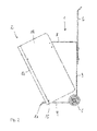
Figur 2- den Abfallbehälter gemäß
Figur 1 in der Seitenansicht; Figur 3- den Abfallbehälter gemäß
Figur 1 in der Vorderansicht; und - Figur 4
- den Abfallbehälter gemäß
Figur 1 mit geschlossener Lade in der Rückansicht.
- FIG. 1
- a perspective view of an embodiment of the waste container according to the invention with open tray;
- FIG. 2
- according to the waste container
FIG. 1 in the side view; - FIG. 3
- according to the waste container
FIG. 1 in front view; and - FIG. 4
- according to the waste container
FIG. 1 with closed drawer in the rear view.
Der in
Im Übergangsbereich zwischen der Rückwand 9 und der Aufstandsseite 4 ist eine Ausnehmung 10 ausgebildet, welche gerade eine horizontale Breite aufweist, die im Wesentlichen der Breite des Reifens 5 entspricht, so dass der Reifen 5 vollständig in der Aufnahme 10 aufgenommen werden kann. Der Reifen 5 ist um die erste Achse x drehbar gelagert, so dass ein Benutzer den Korpus 1 samt Lade 2 über den Griff 6 um die Achse x verschwenken kann, so dass der Abfallbehälter auf dem Reifen 5 aufliegt und damit verschoben werden kann. Die Aufstandsseite 4 weist weiterhin an ihrer dem Übergang zwischen den Seiten 4 und 9 gegenüberliegenden Längskante eine Abkantung 11 auf, über die der Abfallbehälter bei vertikaler Ausrichtung der Rückwand 9 gegen Umkippen abgestützt ist.In the transition region between the
Parallel beabstandet von der ersten Drehachse x ist an der Vorderkante der Aufstandsseite 4 eine zweite Drehachse y ausgebildet, um die die Lade 2 gegenüber dem Korpus 1 verschwenkt werden kann. Dazu weisen die Seitenwände 12 der Lade 2 Lagerstellen 15 auf, die beispielsweise als Bohrungen durch die Seitenwände 12 ausgebildet sein können. Auch die Lade 2 kann im Wesentlichen als U-förmiges Blechformteil ausgebildet sein, mit zwei parallelen Seitenwänden 12, die über eine senkrecht zu den Seitenwänden 12 stehende Vorderwand 13 miteinander verbunden sind. Die Innenseite der Seitenwand 12 und der Vorderwand 13 sind über einen Halterahmen 14 gegeneinander stabilisiert. Der Halterahmen 14 hat weiterhin die Funktion, eine Aufnahme für den Abfallsammeleinsatz 3 zu bilden, so dass der Abfallsammeleinsatz 3 aus dem Halterahmen wahlweise entnommen und in diesen wieder eingesetzt werden kann.Parallel to the first axis of rotation x is at the front edge of the riot side 4, a second axis of rotation y formed around which the
Die Vorderwand 13 der Lade 2 weist an ihrem unteren Ende eine Ausnehmung auf, die eine Auflagerfläche bildet, über die die Lade im geöffneten Zustand auf dem Umkippschutz 11 abgestützt ist.The
Die weiteren
Der gezeigte Kippmechanismus erfordert insbesondere nicht die Verwendung von Federn, Stangen und Gelenken. Vielmehr kann bereits eine Todpunktüberwindung für eine Fixierung der Lade 2 in der Offenposition oder in der Schließposition ausreichend sein. So wird erreicht dass bereits durch leichtes Antippen die Lade 2 zwischen der Offen- und der Schließposition, beispielsweise um 27,8° verschwenkt werden kann, wobei dies bereits ausreichend ist, um in der Offenposition eine ausreichend große Öffnung für das Befüllen mit Hausmüll bereitgestellt ist, oder um den Abfallsammeleinsatz 3 zu entnehmen oder in den Halterahmen 14 wieder einzusetzen.In particular, the tilting mechanism shown does not require the use of springs, rods and joints. Rather, already a dead center overcome for a fixation of the
Um ein geräuscharmes Öffnen und Schließen der Lade 2 zu ermöglichen, können im Halterahmen 14 für den Abfallsammeleinsatz 3 Anschlagpuffer vorgesehen sein. Diese stützen sich in der Offenposition an der Innenseite der oberen Korpuswand 8 ab und lagern in der Schließstellung an der Korpusrückwand 9.In order to allow a low-noise opening and closing of the
Der Korpus 1 und die Lade 2 können beispielsweise aus Aluminiumblech mit einer Materialstärke von 5 mm gefertigt werden. Dazu reichen aus dem Stand der Technik hinreichend bekannte Herstellungsverfahren, umfassend Laserschneiden und Blechbiegeverfahren. Alle notwendigen Verbindungen können über Verschraubungen oder mit Hilfe von Sprengringen, etwa zur Fixierung der Räder auf Achsen, erfolgen.The body 1 and the
Die in der vorstehenden Beschreibung, in den Zeichnungen sowie in den Ansprüchen offenbarten Merkmale der Erfindung können sowohl einzeln als auch in beliebiger Kombination für die Verwirklichung der Erfindung wesentlich sein.The features of the invention disclosed in the foregoing description, in the drawings and in the claims may be essential to the realization of the invention both individually and in any combination.
Claims (12)
Applications Claiming Priority (1)
| Application Number | Priority Date | Filing Date | Title |
|---|---|---|---|
| DE202015100173.8U DE202015100173U1 (en) | 2015-01-15 | 2015-01-15 | Mobile waste bin |
Publications (2)
| Publication Number | Publication Date |
|---|---|
| EP3045408A1 true EP3045408A1 (en) | 2016-07-20 |
| EP3045408B1 EP3045408B1 (en) | 2017-09-27 |
Family
ID=52479000
Family Applications (1)
| Application Number | Title | Priority Date | Filing Date |
|---|---|---|---|
| EP15195433.6A Not-in-force EP3045408B1 (en) | 2015-01-15 | 2015-11-19 | Mobile waste container |
Country Status (5)
| Country | Link |
|---|---|
| EP (1) | EP3045408B1 (en) |
| DE (1) | DE202015100173U1 (en) |
| DK (1) | DK3045408T3 (en) |
| ES (1) | ES2645519T3 (en) |
| LT (1) | LT3045408T (en) |
Cited By (2)
| Publication number | Priority date | Publication date | Assignee | Title |
|---|---|---|---|---|
| CN112896878A (en) * | 2021-01-27 | 2021-06-04 | 重庆工程职业技术学院 | Building rubbish cleaning device |
| WO2021257715A1 (en) * | 2020-06-17 | 2021-12-23 | Heaney Ronan | Receptacle with expandable cavity |
Citations (4)
| Publication number | Priority date | Publication date | Assignee | Title |
|---|---|---|---|---|
| DE7124425U (en) * | 1972-01-05 | Wagner E Kg | Tiltable container, especially for hospitals and maternity homes | |
| DE9312931U1 (en) * | 1993-08-28 | 1993-11-04 | Hygiene Service Gmbh | Intimate hygiene collector |
| EP1369360A1 (en) | 2002-05-21 | 2003-12-10 | Nord Etudes Industrielles | Receptacle for separate collecting of refuse |
| EP1598289A1 (en) * | 2003-02-07 | 2005-11-23 | Selecont Soluciones Ecologicas, S.L. | Refuse sorting container |
-
2015
- 2015-01-15 DE DE202015100173.8U patent/DE202015100173U1/en not_active Expired - Lifetime
- 2015-11-19 ES ES15195433.6T patent/ES2645519T3/en active Active
- 2015-11-19 LT LTEP15195433.6T patent/LT3045408T/en unknown
- 2015-11-19 DK DK15195433.6T patent/DK3045408T3/en active
- 2015-11-19 EP EP15195433.6A patent/EP3045408B1/en not_active Not-in-force
Patent Citations (4)
| Publication number | Priority date | Publication date | Assignee | Title |
|---|---|---|---|---|
| DE7124425U (en) * | 1972-01-05 | Wagner E Kg | Tiltable container, especially for hospitals and maternity homes | |
| DE9312931U1 (en) * | 1993-08-28 | 1993-11-04 | Hygiene Service Gmbh | Intimate hygiene collector |
| EP1369360A1 (en) | 2002-05-21 | 2003-12-10 | Nord Etudes Industrielles | Receptacle for separate collecting of refuse |
| EP1598289A1 (en) * | 2003-02-07 | 2005-11-23 | Selecont Soluciones Ecologicas, S.L. | Refuse sorting container |
Cited By (2)
| Publication number | Priority date | Publication date | Assignee | Title |
|---|---|---|---|---|
| WO2021257715A1 (en) * | 2020-06-17 | 2021-12-23 | Heaney Ronan | Receptacle with expandable cavity |
| CN112896878A (en) * | 2021-01-27 | 2021-06-04 | 重庆工程职业技术学院 | Building rubbish cleaning device |
Also Published As
| Publication number | Publication date |
|---|---|
| DK3045408T3 (en) | 2017-11-13 |
| DE202015100173U1 (en) | 2015-01-29 |
| ES2645519T3 (en) | 2017-12-05 |
| LT3045408T (en) | 2017-10-25 |
| EP3045408B1 (en) | 2017-09-27 |
Similar Documents
| Publication | Publication Date | Title |
|---|---|---|
| DE202009018851U1 (en) | Refrigerating appliance and associated latching means arrangement for retrofitting | |
| EP3217099B1 (en) | Extractor hood | |
| DE202010017933U1 (en) | Fitting for corner cabinets | |
| EP3045408B1 (en) | Mobile waste container | |
| EP3652400A1 (en) | Device for moving a furniture part and piece of furniture | |
| DE2524407C2 (en) | Swiveling support device for a waste collector | |
| DE102016103506B4 (en) | Connector holding structure | |
| EP3517844B1 (en) | Extractor hood | |
| DE102017102892A1 (en) | grill | |
| WO2008055837A2 (en) | Extractor hood | |
| DE202015103952U1 (en) | Device for storing tools | |
| EP2905244B1 (en) | Cover for a storage receptacle and storage receptacle, in particular waste receptacle, with a cover | |
| EP1614642B1 (en) | Device for holding a bag, in particular a refuse bag | |
| EP0083563A1 (en) | Drawer for arranging small objects | |
| DE8137602U1 (en) | STACKABLE STORAGE CONTAINER WITH EXTENDING DRAWER | |
| EP0616956A1 (en) | Refuse container | |
| EP3078612A1 (en) | Device for holding a refuse bag | |
| DE202005008791U1 (en) | Cleaning cart for accommodating cleaning utensils and disposal of garbage has cover, which in each case possesses through hole by which opening of holding frame is accessible in sections with closed position of cover | |
| DE3001703C2 (en) | Large-capacity plastic rubbish bin | |
| DE102005055552A1 (en) | Admission device e.g. for garbage containers, has rack which is partly disguised by viewing screens and which has door frame for entrance door and door frame has upper box part, and two side parts | |
| EP2532608B1 (en) | Device for holding waste bags | |
| DE202009009813U1 (en) | bullet trap | |
| DE202015105862U1 (en) | Stackable container for collection of household waste | |
| DE8624150U1 (en) | Storage container | |
| EP0607975A1 (en) | Enclosure for a refuse container |
Legal Events
| Date | Code | Title | Description |
|---|---|---|---|
| PUAI | Public reference made under article 153(3) epc to a published international application that has entered the european phase |
Free format text: ORIGINAL CODE: 0009012 |
|
| AK | Designated contracting states |
Kind code of ref document: A1 Designated state(s): AL AT BE BG CH CY CZ DE DK EE ES FI FR GB GR HR HU IE IS IT LI LT LU LV MC MK MT NL NO PL PT RO RS SE SI SK SM TR |
|
| AX | Request for extension of the european patent |
Extension state: BA ME |
|
| 17P | Request for examination filed |
Effective date: 20170116 |
|
| RBV | Designated contracting states (corrected) |
Designated state(s): AL AT BE BG CH CY CZ DE DK EE ES FI FR GB GR HR HU IE IS IT LI LT LU LV MC MK MT NL NO PL PT RO RS SE SI SK SM TR |
|
| GRAP | Despatch of communication of intention to grant a patent |
Free format text: ORIGINAL CODE: EPIDOSNIGR1 |
|
| INTG | Intention to grant announced |
Effective date: 20170519 |
|
| GRAS | Grant fee paid |
Free format text: ORIGINAL CODE: EPIDOSNIGR3 |
|
| GRAA | (expected) grant |
Free format text: ORIGINAL CODE: 0009210 |
|
| AK | Designated contracting states |
Kind code of ref document: B1 Designated state(s): AL AT BE BG CH CY CZ DE DK EE ES FI FR GB GR HR HU IE IS IT LI LT LU LV MC MK MT NL NO PL PT RO RS SE SI SK SM TR |
|
| REG | Reference to a national code |
Ref country code: GB Ref legal event code: FG4D Free format text: NOT ENGLISH |
|
| REG | Reference to a national code |
Ref country code: CH Ref legal event code: EP |
|
| REG | Reference to a national code |
Ref country code: FR Ref legal event code: PLFP Year of fee payment: 3 |
|
| REG | Reference to a national code |
Ref country code: AT Ref legal event code: REF Ref document number: 931720 Country of ref document: AT Kind code of ref document: T Effective date: 20171015 |
|
| REG | Reference to a national code |
Ref country code: IE Ref legal event code: FG4D Free format text: LANGUAGE OF EP DOCUMENT: GERMAN |
|
| REG | Reference to a national code |
Ref country code: RO Ref legal event code: EPE |
|
| REG | Reference to a national code |
Ref country code: DE Ref legal event code: R096 Ref document number: 502015001975 Country of ref document: DE |
|
| REG | Reference to a national code |
Ref country code: DK Ref legal event code: T3 Effective date: 20171107 |
|
| REG | Reference to a national code |
Ref country code: SE Ref legal event code: TRGR |
|
| REG | Reference to a national code |
Ref country code: NL Ref legal event code: FP |
|
| REG | Reference to a national code |
Ref country code: ES Ref legal event code: FG2A Ref document number: 2645519 Country of ref document: ES Kind code of ref document: T3 Effective date: 20171205 |
|
| PG25 | Lapsed in a contracting state [announced via postgrant information from national office to epo] |
Ref country code: HR Free format text: LAPSE BECAUSE OF FAILURE TO SUBMIT A TRANSLATION OF THE DESCRIPTION OR TO PAY THE FEE WITHIN THE PRESCRIBED TIME-LIMIT Effective date: 20170927 |
|
| REG | Reference to a national code |
Ref country code: NO Ref legal event code: T2 Effective date: 20170927 |
|
| PG25 | Lapsed in a contracting state [announced via postgrant information from national office to epo] |
Ref country code: BG Free format text: LAPSE BECAUSE OF FAILURE TO SUBMIT A TRANSLATION OF THE DESCRIPTION OR TO PAY THE FEE WITHIN THE PRESCRIBED TIME-LIMIT Effective date: 20171227 Ref country code: LV Free format text: LAPSE BECAUSE OF FAILURE TO SUBMIT A TRANSLATION OF THE DESCRIPTION OR TO PAY THE FEE WITHIN THE PRESCRIBED TIME-LIMIT Effective date: 20170927 Ref country code: RS Free format text: LAPSE BECAUSE OF FAILURE TO SUBMIT A TRANSLATION OF THE DESCRIPTION OR TO PAY THE FEE WITHIN THE PRESCRIBED TIME-LIMIT Effective date: 20170927 Ref country code: GR Free format text: LAPSE BECAUSE OF FAILURE TO SUBMIT A TRANSLATION OF THE DESCRIPTION OR TO PAY THE FEE WITHIN THE PRESCRIBED TIME-LIMIT Effective date: 20171228 |
|
| PG25 | Lapsed in a contracting state [announced via postgrant information from national office to epo] |
Ref country code: CZ Free format text: LAPSE BECAUSE OF FAILURE TO SUBMIT A TRANSLATION OF THE DESCRIPTION OR TO PAY THE FEE WITHIN THE PRESCRIBED TIME-LIMIT Effective date: 20170927 |
|
| PG25 | Lapsed in a contracting state [announced via postgrant information from national office to epo] |
Ref country code: SM Free format text: LAPSE BECAUSE OF FAILURE TO SUBMIT A TRANSLATION OF THE DESCRIPTION OR TO PAY THE FEE WITHIN THE PRESCRIBED TIME-LIMIT Effective date: 20170927 Ref country code: SK Free format text: LAPSE BECAUSE OF FAILURE TO SUBMIT A TRANSLATION OF THE DESCRIPTION OR TO PAY THE FEE WITHIN THE PRESCRIBED TIME-LIMIT Effective date: 20170927 Ref country code: IS Free format text: LAPSE BECAUSE OF FAILURE TO SUBMIT A TRANSLATION OF THE DESCRIPTION OR TO PAY THE FEE WITHIN THE PRESCRIBED TIME-LIMIT Effective date: 20180127 Ref country code: EE Free format text: LAPSE BECAUSE OF FAILURE TO SUBMIT A TRANSLATION OF THE DESCRIPTION OR TO PAY THE FEE WITHIN THE PRESCRIBED TIME-LIMIT Effective date: 20170927 |
|
| REG | Reference to a national code |
Ref country code: DE Ref legal event code: R097 Ref document number: 502015001975 Country of ref document: DE |
|
| PG25 | Lapsed in a contracting state [announced via postgrant information from national office to epo] |
Ref country code: MC Free format text: LAPSE BECAUSE OF FAILURE TO SUBMIT A TRANSLATION OF THE DESCRIPTION OR TO PAY THE FEE WITHIN THE PRESCRIBED TIME-LIMIT Effective date: 20170927 |
|
| PLBE | No opposition filed within time limit |
Free format text: ORIGINAL CODE: 0009261 |
|
| STAA | Information on the status of an ep patent application or granted ep patent |
Free format text: STATUS: NO OPPOSITION FILED WITHIN TIME LIMIT |
|
| PG25 | Lapsed in a contracting state [announced via postgrant information from national office to epo] |
Ref country code: RO Free format text: LAPSE BECAUSE OF NON-PAYMENT OF DUE FEES Effective date: 20170927 Ref country code: PL Free format text: LAPSE BECAUSE OF FAILURE TO SUBMIT A TRANSLATION OF THE DESCRIPTION OR TO PAY THE FEE WITHIN THE PRESCRIBED TIME-LIMIT Effective date: 20170927 |
|
| 26N | No opposition filed |
Effective date: 20180628 |
|
| PG25 | Lapsed in a contracting state [announced via postgrant information from national office to epo] |
Ref country code: MT Free format text: LAPSE BECAUSE OF FAILURE TO SUBMIT A TRANSLATION OF THE DESCRIPTION OR TO PAY THE FEE WITHIN THE PRESCRIBED TIME-LIMIT Effective date: 20170927 |
|
| REG | Reference to a national code |
Ref country code: FR Ref legal event code: PLFP Year of fee payment: 4 |
|
| PG25 | Lapsed in a contracting state [announced via postgrant information from national office to epo] |
Ref country code: SI Free format text: LAPSE BECAUSE OF FAILURE TO SUBMIT A TRANSLATION OF THE DESCRIPTION OR TO PAY THE FEE WITHIN THE PRESCRIBED TIME-LIMIT Effective date: 20170927 |
|
| PG25 | Lapsed in a contracting state [announced via postgrant information from national office to epo] |
Ref country code: HU Free format text: LAPSE BECAUSE OF FAILURE TO SUBMIT A TRANSLATION OF THE DESCRIPTION OR TO PAY THE FEE WITHIN THE PRESCRIBED TIME-LIMIT; INVALID AB INITIO Effective date: 20151119 |
|
| PG25 | Lapsed in a contracting state [announced via postgrant information from national office to epo] |
Ref country code: CY Free format text: LAPSE BECAUSE OF FAILURE TO SUBMIT A TRANSLATION OF THE DESCRIPTION OR TO PAY THE FEE WITHIN THE PRESCRIBED TIME-LIMIT Effective date: 20170927 |
|
| PG25 | Lapsed in a contracting state [announced via postgrant information from national office to epo] |
Ref country code: MK Free format text: LAPSE BECAUSE OF FAILURE TO SUBMIT A TRANSLATION OF THE DESCRIPTION OR TO PAY THE FEE WITHIN THE PRESCRIBED TIME-LIMIT Effective date: 20170927 |
|
| PG25 | Lapsed in a contracting state [announced via postgrant information from national office to epo] |
Ref country code: TR Free format text: LAPSE BECAUSE OF FAILURE TO SUBMIT A TRANSLATION OF THE DESCRIPTION OR TO PAY THE FEE WITHIN THE PRESCRIBED TIME-LIMIT Effective date: 20170927 |
|
| PG25 | Lapsed in a contracting state [announced via postgrant information from national office to epo] |
Ref country code: PT Free format text: LAPSE BECAUSE OF FAILURE TO SUBMIT A TRANSLATION OF THE DESCRIPTION OR TO PAY THE FEE WITHIN THE PRESCRIBED TIME-LIMIT Effective date: 20170927 |
|
| PG25 | Lapsed in a contracting state [announced via postgrant information from national office to epo] |
Ref country code: AL Free format text: LAPSE BECAUSE OF FAILURE TO SUBMIT A TRANSLATION OF THE DESCRIPTION OR TO PAY THE FEE WITHIN THE PRESCRIBED TIME-LIMIT Effective date: 20170927 |
|
| PGFP | Annual fee paid to national office [announced via postgrant information from national office to epo] |
Ref country code: NL Payment date: 20201113 Year of fee payment: 6 |
|
| PGFP | Annual fee paid to national office [announced via postgrant information from national office to epo] |
Ref country code: LU Payment date: 20201110 Year of fee payment: 6 Ref country code: FI Payment date: 20201109 Year of fee payment: 6 Ref country code: SE Payment date: 20201110 Year of fee payment: 6 Ref country code: DE Payment date: 20201130 Year of fee payment: 6 Ref country code: CH Payment date: 20201117 Year of fee payment: 6 Ref country code: GB Payment date: 20201111 Year of fee payment: 6 Ref country code: IT Payment date: 20201027 Year of fee payment: 6 Ref country code: LT Payment date: 20201030 Year of fee payment: 6 Ref country code: DK Payment date: 20201110 Year of fee payment: 6 Ref country code: NO Payment date: 20201110 Year of fee payment: 6 Ref country code: ES Payment date: 20201209 Year of fee payment: 6 Ref country code: FR Payment date: 20201026 Year of fee payment: 6 Ref country code: IE Payment date: 20201110 Year of fee payment: 6 |
|
| PGFP | Annual fee paid to national office [announced via postgrant information from national office to epo] |
Ref country code: BE Payment date: 20201028 Year of fee payment: 6 |
|
| REG | Reference to a national code |
Ref country code: AT Ref legal event code: MM01 Ref document number: 931720 Country of ref document: AT Kind code of ref document: T Effective date: 20201119 |
|
| PG25 | Lapsed in a contracting state [announced via postgrant information from national office to epo] |
Ref country code: AT Free format text: LAPSE BECAUSE OF NON-PAYMENT OF DUE FEES Effective date: 20201119 |
|
| REG | Reference to a national code |
Ref country code: DE Ref legal event code: R119 Ref document number: 502015001975 Country of ref document: DE |
|
| REG | Reference to a national code |
Ref country code: LT Ref legal event code: MM4D Effective date: 20211119 |
|
| REG | Reference to a national code |
Ref country code: DK Ref legal event code: EBP Effective date: 20211130 |
|
| REG | Reference to a national code |
Ref country code: NO Ref legal event code: MMEP |
|
| REG | Reference to a national code |
Ref country code: CH Ref legal event code: PL |
|
| REG | Reference to a national code |
Ref country code: FI Ref legal event code: MAE |
|
| REG | Reference to a national code |
Ref country code: NL Ref legal event code: MM Effective date: 20211201 |
|
| GBPC | Gb: european patent ceased through non-payment of renewal fee |
Effective date: 20211119 |
|
| PG25 | Lapsed in a contracting state [announced via postgrant information from national office to epo] |
Ref country code: SE Free format text: LAPSE BECAUSE OF NON-PAYMENT OF DUE FEES Effective date: 20211120 Ref country code: NO Free format text: LAPSE BECAUSE OF NON-PAYMENT OF DUE FEES Effective date: 20211130 Ref country code: LU Free format text: LAPSE BECAUSE OF NON-PAYMENT OF DUE FEES Effective date: 20211119 Ref country code: LT Free format text: LAPSE BECAUSE OF NON-PAYMENT OF DUE FEES Effective date: 20211119 Ref country code: BE Free format text: LAPSE BECAUSE OF NON-PAYMENT OF DUE FEES Effective date: 20211130 |
|
| REG | Reference to a national code |
Ref country code: BE Ref legal event code: MM Effective date: 20211130 |
|
| PG25 | Lapsed in a contracting state [announced via postgrant information from national office to epo] |
Ref country code: LI Free format text: LAPSE BECAUSE OF NON-PAYMENT OF DUE FEES Effective date: 20211130 Ref country code: FI Free format text: LAPSE BECAUSE OF NON-PAYMENT OF DUE FEES Effective date: 20211119 Ref country code: CH Free format text: LAPSE BECAUSE OF NON-PAYMENT OF DUE FEES Effective date: 20211130 |
|
| PG25 | Lapsed in a contracting state [announced via postgrant information from national office to epo] |
Ref country code: NL Free format text: LAPSE BECAUSE OF NON-PAYMENT OF DUE FEES Effective date: 20211201 |
|
| PG25 | Lapsed in a contracting state [announced via postgrant information from national office to epo] |
Ref country code: IE Free format text: LAPSE BECAUSE OF NON-PAYMENT OF DUE FEES Effective date: 20211119 Ref country code: GB Free format text: LAPSE BECAUSE OF NON-PAYMENT OF DUE FEES Effective date: 20211119 Ref country code: DK Free format text: LAPSE BECAUSE OF NON-PAYMENT OF DUE FEES Effective date: 20211130 Ref country code: DE Free format text: LAPSE BECAUSE OF NON-PAYMENT OF DUE FEES Effective date: 20220601 |
|
| PG25 | Lapsed in a contracting state [announced via postgrant information from national office to epo] |
Ref country code: FR Free format text: LAPSE BECAUSE OF NON-PAYMENT OF DUE FEES Effective date: 20211130 |
|
| PG25 | Lapsed in a contracting state [announced via postgrant information from national office to epo] |
Ref country code: IT Free format text: LAPSE BECAUSE OF NON-PAYMENT OF DUE FEES Effective date: 20211119 |
|
| REG | Reference to a national code |
Ref country code: ES Ref legal event code: FD2A Effective date: 20230217 |
|
| PG25 | Lapsed in a contracting state [announced via postgrant information from national office to epo] |
Ref country code: ES Free format text: LAPSE BECAUSE OF NON-PAYMENT OF DUE FEES Effective date: 20211120 |