EP3045407A1 - Sliced assembly type container, manufacturing, stacking and transportation methods, and finished modules - Google Patents
Sliced assembly type container, manufacturing, stacking and transportation methods, and finished modules Download PDFInfo
- Publication number
- EP3045407A1 EP3045407A1 EP14841749.6A EP14841749A EP3045407A1 EP 3045407 A1 EP3045407 A1 EP 3045407A1 EP 14841749 A EP14841749 A EP 14841749A EP 3045407 A1 EP3045407 A1 EP 3045407A1
- Authority
- EP
- European Patent Office
- Prior art keywords
- lateral
- corner
- disposed
- connecting element
- finished
- Prior art date
- Legal status (The legal status is an assumption and is not a legal conclusion. Google has not performed a legal analysis and makes no representation as to the accuracy of the status listed.)
- Withdrawn
Links
Images


Classifications
-
- B—PERFORMING OPERATIONS; TRANSPORTING
- B65—CONVEYING; PACKING; STORING; HANDLING THIN OR FILAMENTARY MATERIAL
- B65D—CONTAINERS FOR STORAGE OR TRANSPORT OF ARTICLES OR MATERIALS, e.g. BAGS, BARRELS, BOTTLES, BOXES, CANS, CARTONS, CRATES, DRUMS, JARS, TANKS, HOPPERS, FORWARDING CONTAINERS; ACCESSORIES, CLOSURES, OR FITTINGS THEREFOR; PACKAGING ELEMENTS; PACKAGES
- B65D88/00—Large containers
- B65D88/02—Large containers rigid
- B65D88/10—Large containers rigid parallelepipedic
-
- B—PERFORMING OPERATIONS; TRANSPORTING
- B65—CONVEYING; PACKING; STORING; HANDLING THIN OR FILAMENTARY MATERIAL
- B65D—CONTAINERS FOR STORAGE OR TRANSPORT OF ARTICLES OR MATERIALS, e.g. BAGS, BARRELS, BOTTLES, BOXES, CANS, CARTONS, CRATES, DRUMS, JARS, TANKS, HOPPERS, FORWARDING CONTAINERS; ACCESSORIES, CLOSURES, OR FITTINGS THEREFOR; PACKAGING ELEMENTS; PACKAGES
- B65D88/00—Large containers
- B65D88/02—Large containers rigid
- B65D88/12—Large containers rigid specially adapted for transport
- B65D88/121—ISO containers
-
- B—PERFORMING OPERATIONS; TRANSPORTING
- B65—CONVEYING; PACKING; STORING; HANDLING THIN OR FILAMENTARY MATERIAL
- B65D—CONTAINERS FOR STORAGE OR TRANSPORT OF ARTICLES OR MATERIALS, e.g. BAGS, BARRELS, BOTTLES, BOXES, CANS, CARTONS, CRATES, DRUMS, JARS, TANKS, HOPPERS, FORWARDING CONTAINERS; ACCESSORIES, CLOSURES, OR FITTINGS THEREFOR; PACKAGING ELEMENTS; PACKAGES
- B65D88/00—Large containers
- B65D88/52—Large containers collapsible, i.e. with walls hinged together or detachably connected
- B65D88/526—Large containers collapsible, i.e. with walls hinged together or detachably connected with detachable side walls
- B65D88/528—Large containers collapsible, i.e. with walls hinged together or detachably connected with detachable side walls all side walls detached from each other to collapse the container
-
- B—PERFORMING OPERATIONS; TRANSPORTING
- B65—CONVEYING; PACKING; STORING; HANDLING THIN OR FILAMENTARY MATERIAL
- B65D—CONTAINERS FOR STORAGE OR TRANSPORT OF ARTICLES OR MATERIALS, e.g. BAGS, BARRELS, BOTTLES, BOXES, CANS, CARTONS, CRATES, DRUMS, JARS, TANKS, HOPPERS, FORWARDING CONTAINERS; ACCESSORIES, CLOSURES, OR FITTINGS THEREFOR; PACKAGING ELEMENTS; PACKAGES
- B65D90/00—Component parts, details or accessories for large containers
- B65D90/008—Doors for containers, e.g. ISO-containers
-
- B—PERFORMING OPERATIONS; TRANSPORTING
- B65—CONVEYING; PACKING; STORING; HANDLING THIN OR FILAMENTARY MATERIAL
- B65D—CONTAINERS FOR STORAGE OR TRANSPORT OF ARTICLES OR MATERIALS, e.g. BAGS, BARRELS, BOTTLES, BOXES, CANS, CARTONS, CRATES, DRUMS, JARS, TANKS, HOPPERS, FORWARDING CONTAINERS; ACCESSORIES, CLOSURES, OR FITTINGS THEREFOR; PACKAGING ELEMENTS; PACKAGES
- B65D90/00—Component parts, details or accessories for large containers
- B65D90/02—Wall construction
- B65D90/023—Modular panels
- B65D90/026—Parallel slats
-
- B—PERFORMING OPERATIONS; TRANSPORTING
- B65—CONVEYING; PACKING; STORING; HANDLING THIN OR FILAMENTARY MATERIAL
- B65D—CONTAINERS FOR STORAGE OR TRANSPORT OF ARTICLES OR MATERIALS, e.g. BAGS, BARRELS, BOTTLES, BOXES, CANS, CARTONS, CRATES, DRUMS, JARS, TANKS, HOPPERS, FORWARDING CONTAINERS; ACCESSORIES, CLOSURES, OR FITTINGS THEREFOR; PACKAGING ELEMENTS; PACKAGES
- B65D90/00—Component parts, details or accessories for large containers
- B65D90/02—Wall construction
- B65D90/08—Interconnections of wall parts; Sealing means therefor
Definitions
- the disclosure relates generally to structure designing, manufacturing, stacking and transportation of containers, and more specifically to structure designing, manufacturing, stacking and transportation of general cargo containers in consistent with ISO standards.
- Dry containers mainly used to transport general cargo and have a wide range of applications, take an amount of 70-80% in the total containers.
- there are two types of dry containers 20 feet and 40 feet containers.
- ISO International Standardization Organization
- ISO 1496-1 puts forward very strict provisions about the rigidity and inner space of the general cargo container.
- CSC The International Convention for Safe Containers
- UIC Union Internationale des Chemins de Fer
- TIR Transport International Router
- a dry container generally comprises a closed structure having a door disposed at back end, and the structure generally comprises: an underframe comprising two bottom longitudinal beams, two front end bottom corner fittings and two door end bottom corner fittings respectively on both ends of the two bottom longitudinal beams, a front end bottom beam connected between the two front end bottom corner fittings, a doorsill connected between the two door end bottom corner fittings, a plurality of bottom crossbeams each connected between the two bottom longitudinal beams, and a floor laid on the bottom crossbeams; four corner pillars comprise two front end corner pillars corresponding to two front end bottom corner fittings and two door end corner pillars corresponding to two door end corner fitting; two lateral walls, each lateral wall is correspondingly connecting to the front end corner pillar at front end and connecting to back end the corner pillar at back end; front wall, connected two front end corner pillar between; a door mounted between two back end corner pillar; and a top frame comprising two top longitudinal beams which are respectively on two front end top corner fittings and two
- the container is generally manufactured as whole, that is, after all parts are assembled and welded to from a complete box, a series of subsequent processes such as sand-blasting, painting, floor mounting are performed on the whole box.
- traditional way is to improve the automation degree of the basic processes such as welding and painting by continuously increasing/improving the automation equipments.
- the disclosure aims to overcome the shortcomings of the existing technology, and provides a new sliced assembly type container, which, under the condition that all requirements about a common cargo container in ISO are satisfied, can improve the normal technology of manufacturing container as whole to a new technology of manufacturing and assembling finished modules, which can bring about a revolutionary improvement to structural designing, manufacturing, stacking and transporting of the containers.
- the disclosure provides a sliced assembly type container, the sliced assembly type container is in consistent with requirements about a general cargo container in ISO and comprises a bottom finished module, two lateral finished modules, two door finished modules, top finished a module, and a front finished module, the two door finished modules are respectively hinged to a door end of lateral bodies of the two lateral finished modules, wherein:
- the bottom finished module comprises: a bottom body; two bottom lateral connecting parts, respectively disposed on both sides of the bottom body, to fixedly connect the two lateral finished modules, each of the bottom lateral connecting parts comprises a lateral connecting element, a first corner connecting element at a door end of the lateral connecting element, and a second corner connecting element at a front end of the lateral connecting element; and a bottom front connecting part, disposed at a front end of the bottom body, to connect the front finished module.
- the lateral finished modules comprises: a lateral body; lateral bottom connecting parts, disposed on a bottom side of the lateral body, to fixedly connect the bottom finished module, each of the lateral bottom connecting parts comprises a lateral connecting element, a first corner connecting element at a door end of the lateral connecting element, and a second corner connecting element at a front end of the lateral connecting element; lateral top connecting parts, disposed on a top side of the lateral body, to fixedly connect the top finished module, each of the lateral top connecting parts comprises a lateral connecting element, a first corner connecting element at a door end of the lateral connecting element, and a second corner connecting element at a front end of the lateral connecting element; and a lateral front connecting part, disposed at a front end of the lateral body, to connect the front finished module.
- the top finished module comprises: a top body; two top lateral connecting parts, respectively disposed on both sides of the top body, to fixedly connect the two lateral finished modules, each of the top lateral connecting parts comprises a lateral connecting element, a first corner connecting element at a door end of the lateral connecting element, and a second corner connecting element at a front end of the lateral connecting element; and a top front connecting part, disposed at a front end of the top body, to connect the front finished module.
- the front finished module comprises: a front body; a front bottom connecting part, disposed on a bottom side of the front body, to connect the bottom finished module; two front lateral connecting parts, respectively disposed on both sides of the front body, to connect the two lateral finished modules; and a front top connecting part, disposed on a top side of the front body, to connect the top finished module.
- the sliced assembly type container is in consistent with requirements about container in CSC and/or UIC.
- the sliced assembly type container is in consistent with requirements about a container in TIR.
- the door finished modules and the lateral finished modules may be coupled together as one finished module; or, the door finished modules and the lateral finished modules may be two finished modules separated from each other.
- At least one pair of the eight pairs of the corner connection elements may be fixedly connected together by welding.
- the front finished module may be hinged to one module of the two lateral finished modules, the bottom finished module, and the top finished module; and the front finished module may be fixedly connected to the rest modules of the two lateral finished modules, the bottom finished module, and the top finished module via a connecting piece and/or a structural adhesive.
- the front finished module may be assembled with the lateral finished modules, the bottom finished module or top finished module in advance in a factory, so as to facilitate stacking/transporting.
- the disclosure further provides a method for manufacturing a sliced assembly type container, which comprises: a manufacturing process of finished modules for separately manufacturing the bottom finished module, the two lateral finished modules, the two door finished modules, the top finished module, and the front finished module; and an assembling process of the container for assembling the finished modules together, the assembling process is based on the bottom finished module, and the assembling process comprises sealing coupled portions between the modules by applying a glue, an adhesive tape or adhesive sheet; wherein the two door finished modules are being able to be coupled to the two lateral finished modules during the manufacturing process of finished modules in advance, or able to be assembled with the two lateral finished modules during the assembling process of the container.
- the method comprises, between the manufacturing process of finished modules and the assembling process of the container: stacking the manufactured finished modules.
- both the manufacturing process of finished modules and the assembling process of the container are able to be completed in manufacturing site.
- the manufacturing process of finished modules is able to be completed at manufacturing site, and the assembling process of the container is able to be completed at delivery site.
- the disclosure further provide a method for stacking and transporting the sliced assembly type container, which comprises the following steps: arranging the bottom finished module at bottom; respectively stacking the front finished module, the two lateral finished modules, and the two door finished modules on the bottom finished module; stacking the top finished module at top, and packing the finished modules together to form a stacking and transporting basic unit.
- stacking and transporting method may further comprise: stacking a plurality of the transporting basic units together to form a stacking and transporting unit.
- the disclosure further provides a bottom finished module for the sliced assembly type container.
- the bottom finished module comprises: a bottom body; two bottom lateral connecting parts, respectively disposed on both sides of the bottom body, to fixedly connect the two lateral finished modules, each of the bottom lateral connecting parts comprises a lateral connecting element, a first corner connecting element at a door end of the lateral connecting element, and a second corner connecting element at a front end of the lateral connecting element; and a bottom front connecting part, disposed at a front end of the bottom body, to connect the front finished module; wherein the bottom body comprises two set of door end bottom corner fittings, bottom longitudinal beams and front end bottom corner fittings on both sides thereof, a front end bottom beam connected between the two front end bottom corner fittings, a doorsill connected between the two door end bottom corner fittings, bottom crossbeams each connected between the two bottom longitudinal beams, and a floor; the first corner connecting element is disposed on a top of the door end bottom corner fittings, the second
- the disclosure further provides a top finished module for a sliced assembly type container.
- the sliced assembly type container is in consistent with requirements about a common cargo container in ISO;
- the top finished module comprises: a top body; two top lateral connecting parts, respectively disposed on both sides of the top body, to fixedly connect the two lateral finished modules, each of the top lateral connecting parts comprises a lateral connecting element, a first corner connecting element at a door end of the lateral connecting element, and a second corner connecting element at a front end of the lateral connecting element; and a top front connecting part, disposed at a front end of the top body, to connect the front finished module;
- the top body comprises two set of door end top corner fittings, top longitudinal beams, and front end top corner fittings on both sides, a front end top beam connected between the two front end top corner fittings, a lintel connected between the two door end top corner fittings, and a top plate;
- the first corner connecting element is disposed on a bottom of the door end
- the disclosure further provides a lateral finished module for a sliced assembly type container.
- the lateral finished module comprises: a lateral body; lateral bottom connecting parts, disposed on a bottom side of the lateral body, to fixedly connect the bottom finished module, each of the lateral bottom connecting parts comprises a lateral connecting element, a first corner connecting element at a door end of the lateral connecting element, and a second corner connecting element at a front end of the lateral connecting element; lateral top connecting parts, disposed on a top side of the lateral body, to fixedly connect the top finished module, each of the lateral top connecting parts comprises a lateral connecting element, a first corner connecting element at a door end of the lateral connecting element, and a second corner connecting element at a front end of the lateral connecting element; and a lateral front connecting part, disposed at a front end of the lateral body, to connect the front finished module; wherein the first corner connecting element disposed on the bottom of the door end corner pillar, the
- the disclosure further provides a front finished module for the sliced assembly type container.
- the front finished module comprises: a front body; a front bottom connecting part, disposed on a bottom side of the front body, to connect the bottom finished module; two front lateral connecting parts, respectively disposed on both sides of the front body, to connect the two lateral finished modules; and a front top connecting part, disposed on a top side of the front body, to connect the top finished module.
- the normal technology of manufacturing a container as whole is improved to a new technology manufacturing and assembling various finished modules by dividing the container to a bottom module, a top module, two lateral modules, two doors and a front module, and performing processes such as welding and painting on those finished modules, and designing connection relations of the respective finished modules, all requirements about a common cargo container in ISO can be satisfied, thus a revolutionary improvement is brought for the structural designing, manufacturing, stacking and transporting of the containers.
- a sliced assembly type container comprises: a bottom finished module 1, two lateral finished modules 2 and 3, a front finished module 4, a top finished module 5, and two door finished modules 6, 7. Wherein each of the finished modules has been treated by processes such as welding, painting, and necessary inner sealing, can be circulated as a standard part.
- the sliced assembly type container is in consistent with requirements about a general cargo container in ISO and in consistent with requirements about a container in CSC, UIC and TIR.
- the structure of the sliced assembly type container of the disclosure is achieved, under the condition of achieving requirements about a general cargo container in ISO and requirements about a container in CSC, UIC and TIR, after structures of the respective modules are inventively designed/optimized.
- the bottom finished module 1 comprises a bottom body 11, two bottom lateral connecting parts 12, 13, and a bottom front connecting part 14.
- the bottom body 11 comprises two set of door end bottom corner fittings 111, bottom longitudinal beams 112 and front end bottom corner fittings 113 respectively positioned on both sides thereof, a front end bottom beam 114 connected between the two front end bottom corner fittings 113, a doorsill 115 connected between the two door end bottom corner fittings 111, several bottom crossbeams 116 connected between the two bottom longitudinal beams 112, and a floor 117.
- the two bottom lateral connecting parts 12, 13 are disposed on both sides of the bottom body 11, to fixedly connect the two lateral finished modules 2, 3, respectively.
- the bottom front connecting part 14 is disposed at a front end of the bottom body 11, to fixedly connect the front finished module 4.
- the bottom lateral connecting part 12 comprises a first corner connecting element 121 disposed on a top of the door end bottom corner fitting, a second corner connecting element 122 on a top of the front end bottom corner fitting, and a lateral connecting element 123 on a top of the bottom longitudinal beam on the same side of the bottom body 11.
- the bottom lateral connecting parts 13 comprises a first corner connecting element 131 disposed on a top of the door end bottom corner fitting, a second corner connecting element 132 on a top of the front end bottom corner fitting, and a lateral connecting element 133 on tops of the bottom longitudinal beams on the same side of the bottom body 11.
- the bottom front connecting part 14 is equivalent to comprise only one lateral connecting element. It would be noted, in case that an inner sealing is needed, for example, in case that the floor 117 is made from a wood/wood-bamboo material, any necessary sealing process relating to the floor 117 in the bottom finished module 1 has been performed.
- the bottom body 11 may be understood as a bottom structure of a traditional container, and respective connecting parts 12, 13, 14 are some newly added structures onto the bottom body 11 for sake of module assembling.
- the first corner connecting element of the bottom lateral connecting parts may have a plug-in structure, and the plug-in structure may comprise a vertically extending protrusion or receiving cavity.
- the structure of the first corner connecting element may be a plug-in structure selected from below:
- the first corner connecting element may have an overlapped structure.
- the structure of the first corner connecting element may be selected from any of the overlapped structures below:
- the second corner connecting element of the bottom lateral connecting parts may have an overlapped structure.
- the structure of the second corner connecting element is selected from any of the overlapped structures below:
- the second corner connecting element comprises a plug-in structure
- the plug-in structure may comprise a vertically extending protrusion or receiving cavity.
- the connection structure of the second corner connecting element is selected from any one of the plug-in structures below:
- the first corner connecting element comprises upwardly protruding protrusion, and a connecting hole is disposed in the protrusion;
- the second corner connecting element has a horizontally overlapping surface or a vertically overlapping surface, and a connecting hole is disposed to pass through the overlapping surface.
- the lateral connecting element of the bottom lateral connecting part comprises a horizontally extending abutting wall, and a connecting hole is disposed in the horizontally extending abutting wall; or, the bottom lateral connecting parts comprises a vertically extending abutting wall, and a connecting hole is disposed in the vertically extending abutting wall.
- the top finished module 5 comprises a top body 51, two top lateral connecting parts 52, 53, and a top front connecting part 54.
- the top body 51 comprising two sets of door end top corner fittings 511, top longitudinal beams 512 and front end top corner fittings 513 positioned on both sides thereof, a front end top beam 514 connected between the two front end top corner fittings 513, a lintel 515 connected between the two door end top corner fittings 511, and a top plate 517.
- the two top lateral connecting parts 52, 53 are disposed on both sides of the top body 51, to fixedly connect the two lateral finished modules 2, 3, respectively.
- the top front connecting part 54 is disposed at a front end of the top body 51, to fixedly connect the front finished module 4.
- the top lateral connecting parts 52 comprises a first corner connecting element 521 disposed on a bottom of the door end top corner fitting, a second corner connecting element 522 on a top of the front end top corner fitting, and a lateral connecting element 523 on a bottom of the top longitudinal beam on the same side of the top body 51.
- the top lateral connecting parts 53 comprises a first corner connecting element 531 disposed on a top of the door end bottom corner fitting, a second corner connecting element 532 on a bottom of the front end top corner fitting, and a lateral connecting element 533 on a bottom of the top longitudinal beam on the same side of the top body 51.
- the lateral connecting element 533 has a horizontal abutting wall structure, and a mounting hole 5331 is disposed therein.
- the top finished module 5 may further comprises a reinforcing plate 519 mounted on an inner side of the top longitudinal beams 512.
- a top of the reinforcing plate 519 abuts against a top of the top longitudinal beams 512
- a side of the reinforcing plate 519 is welded on an inner side of the top longitudinal beams 512
- a bottom of the reinforcing plate 519 abuts against the lateral connecting element 533.
- one reinforcing plate 519 is disposed on each side of every mounting hole 5331.
- the quantity and position of the reinforcing plate 519 may be varied depending on the actual top longitudinal beams 512 and the lateral connecting element 533.
- the top front connecting part 54 is equivalent to comprise only one lateral connecting element.
- the top body 51 may be understood as a top structure of a traditional container, and respective connecting parts 52, 53, 54 are some newly added structures onto the top body 51 for sake of module assembling.
- the first corner connecting element may have a plug-in structure, and the plug-in structure may comprise a vertically extending protrusion or receiving cavity.
- the structure of the first corner connecting element is selected from any one of the plug-in structures below:
- the first corner connecting element may have an overlapped structure.
- the structure of the first corner connecting element is selected from any of the overlapped structures below:
- the second corner connecting element comprises an overlapped structure.
- the structure of the second corner connecting element is selected from any of the overlapped structures below:
- the second corner connecting element comprises a plug-in structure
- the plug-in structure may comprise a vertically extending protrusion or receiving cavity.
- the connection structure of the second corner connecting element connection structure is selected from any one of the plug-in structures below:
- the first corner connecting element comprises a downwardly protruding protrusion, and a connecting hole is disposed in the protrusion;
- the second corner connecting element has a horizontally overlapping surface or a vertically overlapping surface, and a connecting hole traversing the overlapping surface is disposed therein.
- the lateral connecting element of the top lateral connecting part comprises a horizontally extending abutting wall, and a connecting hole is disposed in the abutting wall.
- the abutting wall may have a protruding downward outer side edge at the outside thereof; or, the abutting wall may have a protruding downward outer side edge at the outside and a protruding downward inner side edge at the inside thereof.
- the top finished module may further comprises a reinforcing plate welded on the top longitudinal beams, and the reinforcing plate has a top abutting against the top longitudinal beams and a bottom abutting against the abutting wall.
- the lateral connecting element of the top lateral connecting parts comprises a vertical extending abutting wall, and a connecting hole is disposed in the abutting wall.
- the top front connecting part comprises a vertical extending abutting wall, and a connecting hole is disposed in the abutting wall.
- top finished module 5 is generalized, and a more details will be followed with respect to the description about connection relations of the top finished module 5 and the lateral finished modules 2, 3 as well as the front finished module 4 by referring to the drawings.
- the lateral finished module 2 comprises a lateral body 21, lateral bottom connecting parts 22, lateral top connecting parts 23, a lateral front connecting part 24, and a door finished module 6.
- the lateral body 21 comprises a lateral wall 211, a front end corner pillar 212 connected to a front end side of the lateral wall 211, and a door end corner pillar 213 connected to a door end side of the lateral wall 211.
- the lateral bottom connecting part 22 is disposed on a bottom side of the lateral body 21, to fixedly connect the bottom finished module 1.
- the lateral top connecting parts 23 are disposed on a top side of the lateral body 21, to fixedly connect the top finished module 5.
- the lateral front connecting part 24 is disposed at a front end of the lateral body 21, to fixedly connect the front finished module 4.
- the door finished module 6 is disposed at a door end of the lateral body 21, specifically, is hinged to the corresponding door end corner pillar 213 of the lateral body 21.
- the structure of the lateral finished module 3 is similar to that of the lateral finished module 2, and comprises the door finished modules 7.
- the door finished module 7 cooperates with the door finished module 6 to form the door of the sliced assembly type container.
- the lateral front connecting part 24 is equivalent to comprise only one lateral connecting element.
- the side bodies 21, 31 may be understood as top structures of a traditional container, and the respective connecting parts 22, 23, 24, 32, 33, 34 are some newly added structures onto the side bodies 21, 31 for sake of module assembling.
- the door finished modules 6, 7 may be understood as structures of the door of a traditional container.
- the first corner connecting element of the lateral bottom connecting part may have a plug-in structure, and the plug-in structure may comprise a vertically extending protrusion or receiving cavity.
- the structure of the first corner connecting element is selected from any one of the plug-in structures below:
- the first corner connecting element of the lateral bottom connecting part may have an overlapped structure.
- the structure of the first corner connecting element is selected from any of the overlapped structures below:
- the second corner connecting element of the lateral bottom connecting part comprises an overlapped structure.
- the second corner connecting element has a structure selected from any of the overlapped structures below:
- the second corner connecting element is in a shape of L.
- the second corner connecting element of the lateral bottom connecting part may have a plug-in structure, and the plug-in structure may comprise a vertically extending protrusion or receiving cavity.
- the second corner connecting element has a structure selected from any one of the plug-in structures below:
- the first corner connecting element of the lateral bottom connecting part comprises a receiving cavity formed at a bottom of the door end corner pillar, a connecting hole is disposed in the bottom of the door end corner pillar corresponding to the receiving cavity;
- the second corner connecting element of the lateral bottom connecting part has a horizontally overlapping surface or a vertically overlapping surface, and a connecting hole is disposed to pass through the overlapping surface.
- the structure of the first corner connecting element of the lateral top connecting part is as same as the structure of the first corner connecting element of the lateral bottom connecting part; the structure of the second corner connecting element of the lateral top connecting part is as same as the structure of the second corner connecting element of the lateral bottom connecting part.
- the structure of the second corner connecting element of the lateral top connecting part is as same as the structure of the first corner connecting element of the lateral bottom connecting part.
- the lateral connecting element of the lateral bottom connecting part comprises a horizontally extending abutting wall, and a connecting hole is disposed in the abutting wall.
- the abutting wall may have a protruding downward outer side edge at the outside thereof; or, the abutting wall may have a protruding downward outer side edge at the outside thereof, and, the abutting wall may have a protruding downward inner side edge at the inside thereof.
- the lateral connecting element of the lateral top connecting part comprises a horizontally extending abutting wall, and a connecting hole is disposed in the abutting wall.
- the abutting wall may have a protruding upward inner side edge at the inside thereof.
- the lateral front connecting part comprises a vertically extending abutting wall, and a connecting hole is disposed in the abutting wall.
- the lateral finished module may further comprise door finished modules hinged to a door end of the lateral body.
- the front finished module 4 comprises a front body 41, a front bottom connecting part 42, two front lateral connecting parts 43, 44, and a front top connecting part 45.
- the front body 41 is equivalent to an end wall.
- the front bottom connecting part 42 is disposed on a bottom side of the front body 41, to fixedly connect the bottom finished module 1.
- the front bottom connecting part 42 is equivalent to comprise only one lateral connecting element.
- the two front lateral connecting parts 43, 44 are disposed on both sides of the front body 41, to fixedly connect the two lateral finished modules 2, 3, respectively.
- the front lateral connecting parts 43, 44 are equivalent to each comprise only one lateral connecting element.
- the front top connecting part 45 is disposed on a top side of the front body 41, to fixedly connect the top finished module 5.
- the front top connecting part 45 is equivalent to comprise only one lateral connecting element.
- the front body 41 may be understood as an end wall structure without containing a corner fitting and a corner pillar in a traditional container, and respective connecting parts 42, 43, 44, 45 are some newly added structures based on the front body 41 for sake of module assembling.
- the front bottom connecting part comprises a horizontally extending abutting wall, and a connecting hole is disposed in the abutting wall.
- the abutting wall may have a protruding downward outer side edge disposed at the outside thereof; or, the abutting wall may have a protruding downward outer side edge at the outside thereof, and, the abutting wall may have a protruding downward inner side edge at the inside thereof.
- the front top connecting part comprises a vertically extending abutting wall, and a connecting hole is disposed in the abutting wall.
- the front lateral connecting part comprises a vertically extending abutting wall, and a connecting hole may be disposed in the vertically extending abutting wall.
- the sliced assembly type container of this embodiment differs from that of previous preferred embodiments mainly in: the door finished module 6 and the lateral finished module 2 are independent to each other, that is, they are not coupled into one; similarly, the door finished modules 7 and the lateral finished module 3 are independent with respect to each other, that is, they are not coupled into one.
- the whole sliced assembly type container may be understood to be formed by five finished modules (the coupled side and door finished modules can be taken as a single lateral finished module ); moreover, in the embodiment as shown in Fig. 3 , the whole sliced assembly type container may be understood to be formed by seven finished modules (each of the lateral finished modules and the door finished modules which are separated from each other can be taken as a single finished module ).
- the bottom finished module 1 and the lateral finished modules 2, 3 may be fixedly connected together via a connecting piece and/or a structural adhesive
- the lateral finished modules 2, 3 and the top finished module 5 may be fixedly connected together via a connecting piece and/or a structural adhesive
- the front finished module 4 and the two lateral finished modules 2, 3 may be fixedly connected together via a connecting piece and/or a structural adhesive
- the bottom finished module 1 and the top finished module 5 may be fixedly connected together via a connecting piece and/or a structural adhesive.
- sealing may be performed in various ways, for example, glue is applied on both sides of the coupled portion, or an adhesive tape is applied on a coupling surface, alternatively, an adhesive sheet is applied on a coupling surface.
- the modules 1-5 are fixedly connected to each other and un-detachable after assembling.
- a connecting piece if a bolt is effective as same as a rivet, the rivet is selected, so as to assure reliability of the sliced assembly type container.
- a detachable connecting piece may be selected to perform fixed connection among the modules 1-5.
- the front finished module 4 is independent with respect to the bottom finished module 1, the lateral finished modules 2, 3 and the top finished module 5.
- the front finished module 4 and other modules may be connected together via a rotatable element such as a hinge to form a group of modules, for example, the front finished module 4 is connected to one of the two lateral finished modules 2, 3 via a hinge or the like to form an assembly; or, the front finished module 4 is connected to the bottom finished module 1 via a hinge or the like to form an assembly; or, the front finished module 4 is connected to the top finished module 5 via a hinge or the like to form an assembly.
- a rotatable element such as a hinge to form a group of modules
- the front finished module 4 is connected to one of the two lateral finished modules 2, 3 via a hinge or the like to form an assembly
- the front finished module 4 is connected to the bottom finished module 1 via a hinge or the like to form an assembly
- the front finished module 4 is connected to the top finished module 5 via a hinge or the like to form an assembly
- welding may be applied to some of eight corners for connection.
- welding may be applied to one or more of the corners, and may be applied to all the eight corners.
- no matter the door finished modules 6, 7 are independent, or coupled together with the lateral finished modules 2, 3 in advance; or, no matter the front finished module 4 is independent, or is coupled together with the other modules 1, 2, 3, 5 in advance, there will be little impact on the whole structure of the sliced assembly type container of the disclosure (as a whole after assembling).
- no matter whether coupling is performed in advance the door finished modules and the front finished module are required to be a sliced type finished module. Therefore, a more specific description will be provided by taking structures of some preferred embodiments for example.
- the disclosure provides a method for manufacturing the above sliced assembly type container, which comprises the following steps:
- a stacking process of the finished modules may be further provided, so as to provide a buffer for the manufacturing process of the finished modules and the assembling processes of the container.
- the production flexibility of the container can be substantively improved, for example, in non-peak season, separate manufacturing of the finished modules 1-5 can be mainly performed, and stacking can be also performed; moreover, in peak season, assembling of the finished modules 1-5 would be mainly performed.
- manufacturing capability can be relatively more effectively arranged, and a uniform distribution of the manufacturing capability can be achieved.
- separately manufacturing these finished modules 1-5 and assembling the finished modules 1, 5 to form the resultant container may be performed in a manufacturing place.
- the manufacturing place herein may contain a plurality of geographic locations, for example, in case of the most decentralized geographic locations, manufacturing of each of the finished modules and assembling of the container can be separately performed in one dedicated factory.
- the separated manufacturing of these finished modules 1-5 can be arranged to be performed in a manufacturing place far away from the client (delivery place), moreover, assembling of these finished modules 1-5 can be either performed in their manufacturing place(s), or be performed in a delivery place near to the client.
- the processes which have relative strong influence to environment such as welding/painting can be totally controlled within a dedicated manufacturing place in factory; moreover, it is only needed to arrange some assembling devices and testing equipments for assembling of the finished modules in an assembling region at the delivery place.
- Assembling the various finished modules to be the resultant container in consistent with the related standard provisions can be performed like building blocks, or assembling DIY furniture (sealing operation is completed while assembling), so production flexibility can be substantively improved, manufacturing and delivering cost for the whole container con be reduced, and the region which may contaminate environment can be strictly controlled.
- the disclosure provides another method for manufacturing the sliced assembly type container.
- the method of this embodiment compared with the first method shown in Fig. 4A , have the following differences: before assembling process of the container, in the first method, the door finished modules 6, 7 have been coupled with the lateral finished modules 2, 3; however, according to this method, the door finished modules 6, 7 and the lateral finished modules 2, 3 are independent with respect to each other.
- the manufacturing process of the door finished modules and process of assembling the door finished modules with the lateral finished modules are inherently comprised in manufacturing of the side assembling line.
- the manufacturing process of the door finished modules is separately performed, and the process of assembling the door finished modules with the lateral finished modules is arranged downstream to the assembling process of the container.
- the method of this embodiment and the first method in comparison each have its own advantages, for example, by the first method, the burden of stacking/transporting and the subsequent processes for requiring assembling can be reduced; by this method of the embodiment, the assembling process of the other modules is facilitated since the door finished modules are independent, in other words, the assembling process of the other modules can be relatively less restricted by the door finished modules.
- the disclosure provides a stacking/transporting method of the sliced assembly type container.
- the method comprises the following steps: arranging the bottom finished module 1 in a bottom; respectively stacking the front finished module 4, the two lateral finished modules 2, 3, and the two door finished modules 6, 7 (which may be coupled to the lateral finished modules, or separated from the lateral finished modules) on the bottom finished module 1; stacking the top finished module 5 on a top, packing these finished modules 1-5 (or 1-7) together to form a stacking/transporting basic unit 10.
- a plurality of stacking/transporting basic unit 10 may be stacked together to form a stacking/transporting unit, thus a plurality of stacking/transporting basic unit 10 can be received in the occupation space of one standard container. Therefore, by means of performing stacking/transporting after packing, compared with the existing mode of stacking/transporting the whole container, the occupation area and the stacking space can be substantively saved, thus the stacking/transporting cost can be substantively reduced.
- the bottom lateral connecting part 12 of the bottom finished module 1 comprises: the first corner connecting elements 121 on the top of the door end bottom corner fitting 111, the second corner connecting element 122 on the top of the front end bottom corner fitting 113, and the lateral connecting element 123 on the top of the bottom longitudinal beam 112 all disposed the same side of the bottom body 11.
- Each of the lateral bottom connecting part 22 of the lateral finished module 2 comprises: the first corner connecting element 221 at the bottom of the door end corner pillar 213, the second corner connecting element 222 at the bottom of the front end corner pillar 212, and the lateral connecting element 223 at the bottom of the lateral wall 211 of the lateral body 21.
- the first corner connecting element 221 is opposite to the first corner connecting element 121
- the second corner connecting element 222 is opposite to the second corner connecting element 122
- the lateral connecting element 223 is opposite to the lateral connecting element 123.
- the first corner connecting element 121 of the bottom lateral connecting part 12 may comprise a protrusion, a receiving cavity or an overlapping piece.
- the first corner connecting element 221 of the lateral bottom connecting part 22 may correspondingly comprise a receiving cavity, a protrusion or an overlapping piece.
- the first corner connecting element 121 of the bottom lateral connecting part 12 may be fixedly connected to the first corner connecting element 221 of the lateral bottom connecting part 22 together via a connecting piece.
- the second corner connecting element 122 of the bottom lateral connecting part 12 may comprise a protrusion, a receiving cavity or an overlapping piece
- the second corner connecting element 222 of the lateral bottom connecting part 22 may comprise a receiving cavity, a protrusion or an overlapping piece.
- the second corner connecting element 122 of the bottom lateral connecting part 12 may be fixedly connected to the second corner connecting element 222 of the lateral bottom connecting part 22 together via a connecting piece.
- the lateral connecting element 123 of the bottom lateral connecting part 12 may comprise a horizontally extending/vertically extending abutting wall, and the second corner connecting element 223 of the lateral bottom connecting part 22 may correspondingly comprises horizontally extending/vertically extending abutting wall.
- the lateral connecting element 123 of the bottom lateral connecting part 12 may be fixedly connected to the lateral connecting element 223 of the lateral bottom connecting part 22 together via a connecting piece and/or a structural adhesive.
- the bottom finished module 1 and the lateral finished module 2 may be assembled together by welding at a position wherein the first corner connecting element 121 corresponds to the first corner connecting element 221, and also at a position where the second corner connecting element 122 corresponds to the second corner connecting element 222.
- Sealing at a junction of the bottom finished module 1 and the lateral finished module 2 may comprising applying glue, an adhesive tape or an adhesive sheet and the like on a connection coupling surface or on an inner/outer side of the coupling surface.
- the bottom lateral connecting parts 13 and the bottom lateral connecting parts 12 are similar to each other in structure, and the connection relations and sealing modes of the bottom finished module 1 and the lateral finished module 3 are similar to the connection relations and sealing modes of the bottom finished module 1 and the lateral finished module 2, no redundant discussion is repeated.
- connection relations of the lateral finished modules 2, 3 and the bottom finished module 1 at door end corners i.e., junctions of the first corner connecting elements 121/131 and the corresponding first corner connecting elements 221/231.
- Such connection relations may be used for connection of the lateral finished modules 2, 3 and the top finished module 5 at the door end corners.
- connection relations may also be used for connection of the lateral finished modules 2, 3 and the bottom finished module 1 at front end corners.
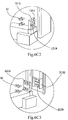
- Fig. 6A which shows a first embodiment, it shows: the door end bottom corner fitting 111, the doorsill 115, and the floor 117 on the bottom body 11 of the bottom finished module 1; the first corner connecting element 121 and the lateral connecting element 123 on the bottom lateral connecting parts 12; the lateral wall 211 and the door end corner pillar 213 on the lateral body 21 of the lateral finished module 2; the first corner connecting element 221 on the lateral bottom connecting part 22; and the connecting piece 91.
- the first corner connecting element 121 comprises an upwardly protruding protrusion 1212.
- a first connecting hole 1214 and two first mounting holes 1215 positioned around the first connecting hole 1214 are disposed to horizontally penetrate into the protrusion 1212.
- the first corner connecting element 221 comprises a receiving cavity formed at a bottom of door end corner pillar 213.
- a second connecting hole 2134 and two second mounting holes 2135 positioned around the second connecting hole 2134 are disposed to horizontally penetrate into the bottom of the door end corner pillar 213 corresponding to the receiving cavity.
- the connecting piece 91 comprises one connecting pin 911 and two fasteners 912.
- the connecting pin 911 is disposed to penetrate into the first connecting hole 1214 and the second connecting hole 2134, and has two third mounting holes 9113 disposed therein.
- the two fasteners 912 are correspondingly disposed to penetrate into the first mounting hole 1215, the second mounting hole 2135, and the third mounting hole 9113.
- the first corner connecting element 121 comprises a base part 1211 disposed at the door end bottom corner fitting 111 and a baffle 1213 disposed on an outer side of the base part 1211.
- the protrusion 1212 protrudes upward from a top side of the base part 1211.
- the two first mounting holes 1215 in the protrusion 1212 are arranged to form an angle with respect to a horizontal plane defined by the bottom body 11. Preferably, the angle is in a range of 30-60°.
- the connecting pin 911 further has a cylindrical base part 9111 and frustum head part 9112, and the two third mounting holes 9113 are threaded holes disposed in the base part 9111 to fit for the two fasteners 912 (bolts in this embodiment).
- the connecting piece 91 in this embodiment is a connecting piece having a locking effect. It would be noted, in other embodiments, the baffle 1213 may be omitted; and in other embodiments, the baffle 1213 may be disposed in the door end corner pillar 213.
- Fig. 6B which shows second embodiment, it is shown therein: the door end bottom corner fittings 111 and the doorsill 115 on the bottom body 11 of the bottom finished module 1; the first corner connecting element 131 on the bottom lateral connecting part 13; the door end corner pillar 313 on the lateral finished module 3; the first corner connecting element 321 on the lateral bottom connecting part 32; and the connecting piece 91.
- the first corner connecting element 131 of the bottom lateral connecting part 13 comprises a connecting block 1311 with a receiving cavity 1312.
- a first connecting hole 1313 is horizontally disposed in the connecting block 1311.
- the first corner connecting element 321 of the lateral bottom connecting part 32 comprises a downwardly protruding protrusion 3211.
- the protrusion 3211 has a second connecting hole 3213 horizontally disposed therein.
- the connecting piece 91 is correspondingly disposed to penetrate into the first connecting hole 1313 and the second connecting hole 3213.
- the connecting piece 91 has a locking effect.
- the connecting piece 91 having a locking effect is a solid rivet which can fill up the first connecting hole 1313 and the second connecting hole 3213 during riveting process.
- the two connecting pieces 91 both may be rivets, alternatively, one of them may by a rivet, and another is a fastener such as bolt.
- numbers of the connecting holes and the connecting pieces may be one or more than three.
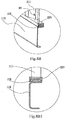
- Fig. 6C which shows a third embodiment, it is shown therein: the door end bottom corner fitting 111 and the doorsill 115 on the bottom body 11 of the bottom finished module 1; the first corner connecting element 121 on the bottom lateral connecting parts 12; the door end corner pillar 213 of the lateral finished module 2; the first corner connecting element 221 on the lateral bottom connecting part 22; and the connecting piece 91.
- the first corner connecting element 121 of the bottom lateral connecting part 12 comprises the upwardly protruding protrusion 1212, and the first connecting hole 1214 is horizontally disposed in the protrusion 1212.
- the first corner connecting element 221 of the lateral bottom connecting part 22 comprises a receiving cavity formed at the bottom of the door end corner pillar 213 and a reinforcing part 2132 being a bottom structural member of the door end corner pillar 213.
- Second connecting holes 2135, 2137 are horizontally disposed in the bottom of the door end corner pillar 213 at positions corresponding to the receiving cavity, and a third connecting hole 2136 is horizontally disposed in the reinforcing part 2132.
- the connecting piece 91 may be a fastener such as a bolt or rivet correspondingly disposed to penetrate into the first connecting hole 1214, the second connecting holes 2135, 2137 and the third connecting hole 2136.
- the first corner connecting element 121 may comprise: the base part 1211 disposed at the door end bottom corner fittings 111, the baffle 1213 disposed on an outer side of the base part 1211, the protrusion 1212 protruding upward from a top side of the base part 1211.
- the door end corner pillar 213 has three-member-structure, which comprises a first corner pillar part 2131 on an inner side thereof and provided with a connecting hole 2135, a second member (i.e., the reinforcing part) 2132 disposed in the meddle thereof and provided with a connecting hole 2136, and a second corner pillar part 2133 disposed on an outer side thereof and provided with a connecting hole 2137.
- the reinforcing part 2132 may be welded together with the second corner pillar part 2133 in advance, then the second corner pillar part 2133 may be welded with the first corner pillar part 2131.
- the reinforcing part 2132 may welded together with the first corner pillar part 2131 in advance, and then, the second corner pillar part 2133 is welded to the first corner pillar part 2131;
- the aforementioned receiving cavity may be formed by cooperation of the reinforcing part 2132 and the first corner pillar part 2131 as well as the second corner pillar part 2133 for correspondingly receiving the protrusion 1212 of the first corner connecting element 121, and the protrusion 1212 may be fixed in the receiving cavity by the two connecting pieces 91.
- numbers of the connecting hole and the connecting piece may be one or more than three. It would be noted, if strength of the first corner pillar part 2131 and the second corner pillar part 2133 are enough, the reinforcing part 2132 may be omitted. In other words, in some cases, the reinforcing part 2132 may not be a necessary structure of the door end corner pillar 213.
- the reinforcing part 2132 may be merely a flat plate structure without inwardly bending parts on both sides of the flat plate.
- an outer end face of the base part 1211 is substantially flush with an outer end face of the doorsill 115.
- a distance wl between the outer end face of the base part 1211 and the outer end face of the door end bottom corner fittings 111 is approximately 57 mm.
- a distance w2 between an outer end face of the baffle 1213 and an outer end face of the door end bottom corner fittings 111 is approximately 4 mm.
- a distance w3 between an outer lateral surface of the baffle 1213 and an outer lateral surface of the door end bottom corner fittings 111 is approximately 3 mm.
- a top surface of the base part 1211 is a horizontal surface, and its length and width are approximately equal to length and width of a horizontal surface of the door end corner pillar 213. In the top surface of the base part 1211, except for areas where the protrusion 1212 extends upward, abutting areas are received, thus the door end corner pillar 213 may be carried well to achieve abutting of the first corner connecting element 121 and the door end corner pillar 213.
- the connecting piece 91 is a connecting piece having a locking effect.
- the connecting piece 91 is a rivet.
- the connecting hole 2135, 2136, 2137 in the door end corner pillar 213 and the connecting hole 1214 in the protrusion 1212 are aligned with each other (refer to the figure at the bottom).
- the rivet is inserted (refer to the figure in the middle)
- the rivet When riveting is completed (refer to the figure at the top), due to a material deformation of the rivet ( solid rivet ) during riveting process, the rivet may fill up these connecting hole 2135, 2136, 2137, 1214, and the gap dl is eliminated. It would be noted, in practical assembling process of the container, when the protrusion 1212 is inserted into the receiving cavity, due to the assembly errors, the connecting hole 1214 and other connecting holes 2135, 2136, 2137 may not be aligned completely.
- performance characteristics of the rivet may be purposefully used to completely fill up the gap dl subsequently, so such hole assembly error (the connecting hole 1214 and other connecting holes 2135, 2136, 2137 are not be aligned completely, a certain deviation, particularly a deviation in vertical direction is presented) may be allowed, consequently, it is not necessary to over strictly control machining accuracy of the finished modules, thus assembling of the container is facilitated.
- the rivet is inserted from inner side to outer side of the container into the corresponding connecting holes
- the rivet may be is inserted from outer side to inner side of the container into the corresponding connecting holes.
- connecting pieces having a locking effect may be used for only a group or a part or all of the connecting holes.
- Figs. 6C2 and 6C3 which shows another variant design based on the structure in Fig. 6C or 6C0 .
- the outer side of the protrusion 1212 is depressed inwardly to form a clasp slot 1219.
- the inner side of the reinforcing part 2132 projects inwardly to form a clasp block 2139, the clasp block 2139 and the clasp slot 1219 may cooperate with each other to facilitate for positioning and/or connecting.
- an indentation (not shown), which may provide a space for the protrusion 1212, is disposed in the bottom of the first corner pillar part on the inner side of the door end corner pillar 213, the protrusion 1212 and the reinforcing part 2132 have a cooperation relation of vertically overlapping with each other,
- the protrusion 1212 may be viewed as a first overlapping piece having a vertically overlapping surface
- the reinforcing part 2132 may be viewed as a second overlapping piece having a vertically overlapping surface, moreover, the second overlapping piece is welded on an inner side of the second corner pillar part at the outer side of the door end corner pillar 213. Since force in vertical direction is carried out by cooperation of the clasp block 2139 and the clasp slot 1219, the connecting piece 91 may be selected from a common fastener, rather than a connecting piece having a locking effect.
- Fig. 6D which shows a fourth embodiment, it shows: the door end bottom corner fitting 111, the bottom longitudinal beams 112, the doorsill 115 and the bottom crossbeam 116 on the bottom body 11 of the bottom finished module 1; the first corner connecting element 121 and the lateral connecting element 123 on the bottom lateral connecting part 12; the door end corner pillar 213 of the lateral finished module 2; the first corner connecting element 221 on the lateral bottom connecting part 22; and the connecting piece 91.
- the first corner connecting element 121 of the bottom lateral connecting part 12 comprises the upwardly protruding protrusion 1212.
- the first corner connecting element 221 of the lateral bottom connecting part 22 comprises a receiving cavity formed at the bottom of the door end corner pillar 213.
- Two second connecting holes 2134 and second mounting holes 2135 disposed in side of each of the second connecting holes 2134 and in communication with the second connecting holes 2134 are horizontally disposed at the bottom of the door end corner pillar 213 corresponding to the receiving cavity.
- the second mounting holes are.
- the connecting piece 91 comprises: two connecting pins 911 having locking effect, disposed to correspondingly penetrate into the first connecting hole 1214 and the second connecting hole 2134; bolts 912, disposed to correspondingly penetrate into the first mounting holes 1215 and the second mounting holes 2135; and nuts 913 in cooperation with the bolts 912.
- the connecting piece 91 may be a connecting piece having locking effect. It would be noted, in other embodiments, numbers of the connecting holes and connecting pieces may be one or more than three.
- the bolt 912 and the nut 913 may be replaced by a rivet.
- Fig. 6E which shows a fifth embodiment. It shows: the door end bottom corner fittings 111 and the doorsill 115 on the bottom body 11 of the bottom finished module 1; the first corner connecting element 121 and the lateral connecting element 123 on the bottom lateral connecting part 12; the door end corner pillar 213 of the lateral finished module 2; the first corner connecting element 221 on the lateral bottom connecting part 22; and the connecting piece 91.
- the first corner connecting element 121 of the bottom lateral connecting part 12 comprises the upwardly protruding protrusion 1212, and the first connecting hole 1214 is horizontally disposed in the protrusion 1212.
- the first corner connecting element 221 of the lateral bottom connecting part 22 comprises a receiving cavity formed at the bottom of the door end corner pillar 213, and the second connecting hole 2134 is horizontally disposed at the bottom of the door end corner pillar 213 corresponding to the receiving cavity.
- the connecting piece 91 may be a bolt having a tail cone and being disposed to correspondingly penetrate into the first connecting hole 1214 and the second connecting hole 2134, and the bolt has locking effect.
- the connecting piece 91 is a connecting piece having a locking effect. It would be noted, in other embodiments, numbers of the connecting holes and connecting pieces may be two or the more.
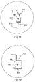
- Fig. 6F which shows a sixth embodiment, it shows therein: the first corner connecting element 121 on the bottom lateral connecting parts 12 of the bottom finished module 1; the door end corner pillar 213 of the lateral finished module 2, the door end corner pillar 213 having a receiving cavity; the first corner connecting element 221 on the lateral bottom connecting part 22; and the connecting piece 91.
- the first corner connecting element 121 of the bottom lateral connecting part 12 comprises a first overlapping piece 1211 having a horizontally overlapping surface, and a first connecting hole 1213 is disposed in the first overlapping piece 1211.
- the first corner connecting element 221 of the lateral bottom connecting part 22 comprises a second overlapping piece 2211 having a horizontally overlapping surface, and a second connecting hole 2213 is disposed in the second overlapping piece 2211.
- the connecting piece 91 may be a fastener such as a bolt or rivet correspondingly disposed to penetrate into the first connecting hole 1213 and the second connecting hole 2213.
- Fig. 6G which shows a seventh embodiment, it shows therein: the first corner connecting element 121 on the bottom lateral connecting parts 12 of the bottom finished module 1; the door end corner pillar 213 of the lateral finished module 2; the first corner connecting element 221 on the lateral bottom connecting part 22; and the connecting piece 91.
- the first corner connecting element 121 of the bottom lateral connecting part 12 comprises a protruding upward protrusion 1212.
- the first corner connecting element 221 of the lateral bottom connecting part 22 comprises a receiving cavity 2211 formed at the bottom of the door end corner pillar 213.
- the receiving cavity 2211 is injected with a filler at a position corresponding to the protrusion 1212, and the filler forms the connecting piece 91 after solidification, such that the first corner connecting element 121 of the bottom finished module 12 is fixedly connected together with the first corner connecting element 221 of the lateral finished module 22.
- the filler may be a glue, a high strength resin, a special cement, or the like.
- the protrusion 1212 is special-shaped, and the protrusion may be designed to have concave and convex parts in mesh with each other according to the actual requirements.
- Fig. 6H which shows an eighth embodiment, it shows therein: the first corner connecting element 121 on the bottom lateral connecting parts 12 of the bottom finished module 1; the door end corner pillar 213 of the lateral finished module 2; the first corner connecting element 221 on the lateral bottom connecting part 22; and the connecting piece 91.
- the first corner connecting element 121 of the bottom lateral connecting part 12 comprises an abutting block 1211 having a receiving cavity
- the first corner connecting element 221 of the lateral bottom connecting part 22 comprises a downwardly protruding protrusion 2211.
- the receiving cavity of the abutting block 1211 is injected with a filler at a position corresponding to the protrusion 2211, and the filler forms the connecting piece 91, after solidification, such that the first corner connecting element 121 of the bottom finished module 12 and the first corner connecting element 221 of the lateral finished module 22 are fixedly connected together.
- the filler may be a glue, a high strength resin, a special cement, or the like.
- the protrusion 2211 is special-shaped, particularly, the protrusion may designed to have concave and convex parts in mesh with each other according to the actual requirements.
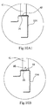
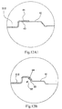
- FIGs. 7A-7E which shows the connection relations of the lateral finished modules 2, 3 and the bottom finished module 1 at the front end corners. These connection relations may be used for the connection of the lateral finished modules 2, 3 and the top finished module 5 at the front end corners.
- Fig. 7A which shows the first embodiment, it shows therein: the floor 117 on the bottom body 11, the second corner connecting element 122 and the lateral connecting element 123 on the bottom lateral connecting part 12, and the bottom front connecting part 14 of the bottom finished module 1; the lateral wall 211, the front end corner pillar 212, the second corner connecting element 222 and the lateral connecting element 223 on the lateral bottom connecting part 22, and the lateral front connecting part 24 of the lateral finished module 2; and the connecting piece 92.
- the second corner connecting element 122 of the bottom lateral connecting part 12 comprises a first overlapping piece 1221 having a horizontally overlapping surface.
- the first overlapping piece 1221 has a shape of L, and has a first connecting hole 1222 disposed therein.
- the second corner connecting element 222 of the lateral bottom connecting part 22 comprises a second overlapping piece 2221 having a horizontally overlapping surface.
- the second overlapping piece 2221 has a shape of L, and has a second connecting hole 2222 disposed therein.
- the connecting part 92 may be a fastener such as a bolt and a rivet correspondingly disposed to penetrate into the first connecting hole 1222 and the second connecting hole 2222.
- the first overlapping piece 1221 has a vertically overlapping surface instead of a horizontally overlapping surface; moreover, the second overlapping piece 2221 has a vertically overlapping surface, too, rather than a horizontally overlapping surface.
- the second overlapping piece may be located at the outer side of the first overlapping piece 1221, rather than above the first overlapping piece 1221.
- the second overlapping piece 2221 and the front end corner pillar 212 are welded together in advance, and the third connecting hole 2121 is disposed in the front end corner pillar 212 at a position corresponding to the second connecting hole 2222 (in conjunction with Fig. 7A1 ).
- the connecting piece 92 has locking effect, preferably, the connecting piece is a rivet.
- the connecting hole 1222 in the first overlapping piece 1221, the connecting hole 2222 in the second overlapping piece 2221, and the connecting hole 2121 in the front end corner pillar 212 are aligned to one another (refer to the figure on the left side).
- the rivet is inserted (refer to the figure in the middle), there is a gap d2 between the rivet and these connecting holes 1222, 2222, 2121.
- the rivet may fill up these connecting holes 1222, 2222, 2121, thus eliminating the gap d2.
- the connecting hole 1222 and other connecting holes 2221, 2121 may not be aligned completely.
- the performance characteristics of the rivet that can completely eliminate the gap d2 afterwards is purposefully used, such that the hole assembly error (i.e., the connecting hole 1222 and other connecting holes 2221, 2121 are not aligned completely, and there is a deviation) may be tolerable.
- the rivet is amounted by inserting into the corresponding connecting hole from inner side to outer side of the container, in other embodiments, the rivet may be amounted by inserting into the corresponding connecting hole from outer side to inner side of the container.
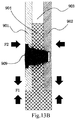
- Fig. 7B which shows the second embodiment, it shows therein: the bottom longitudinal beams 112 on the bottom body 11, the front end bottom corner fittings 113, the front end bottom beam 114, the second corner connecting element 122 and the lateral connecting element 123 on the bottom lateral connecting parts 12, and the bottom front connecting part 14 of the bottom finished module 1; the lateral wall 211, the front end corner pillar 212, the second corner connecting element 222 and the lateral connecting element 223 on the lateral bottom connecting part 22 of the lateral finished module 2; and the connecting piece 92.
- the second corner connecting element 122 of the bottom lateral connecting part 12 comprises an abutting block 1221 having a receiving cavity 1222.
- the abutting block 1221 and the receiving cavity 1222 disposed in the abutting block each has a shape of L.
- the first connecting hole 1223 is horizontally disposed in the abutting block 1221.
- the second corner connecting element 221 of the lateral bottom connecting part 22 comprises a downwardly protruding protrusion 2211.
- the protrusion 2211 has a shape of L, and the second connecting hole 2213 is horizontally disposed in the protrusion 2211.
- the connecting piece 92 may be a connecting piece having a locking effect and is correspondingly disposed to penetrate into the first connecting hole 1223 and the second connecting hole 2213.
- this connecting piece may be a rivet.
- Fig. 7C which shows the third embodiment, it shows therein: the second corner connecting element 122 and the lateral connecting element 123 on the bottom lateral connecting parts 12, and the bottom front connecting part 14 of the bottom finished module 1; the lateral wall 211, the front end corner pillar 212, the second corner connecting element 222 and the lateral connecting element 223 on the lateral bottom connecting part 22, and the lateral front connecting part 24 of the lateral finished module 2; and the connecting piece 92.
- the second corner connecting element 122 of the bottom lateral connecting part 12 comprises a first overlapping piece comprising a first overlapping part 1221 which has a vertically overlapping surface and a second overlapping piece 1222 which has a horizontally overlapping surface.
- a first connecting hole 1223 is horizontally disposed in the first overlapping piece 1221, and a second connecting hole 1224 is disposed in the second overlapping piece 1222.
- the second corner connecting element 222 of the lateral bottom connecting part 22 comprises a first overlapping piece which includes a third overlapping piece 2221 having a vertically overlapping surface and a fourth overlapping piece 2222 having a horizontally overlapping surface.
- the third connecting hole 2223 is horizontally disposed in the third overlapping piece 2221.
- a fourth connecting hole 2224 is disposed in the fourth overlapping piece 2222.
- the connecting piece 92 further includes a connecting piece having locking effect and correspondingly disposed to penetrate into the first connecting hole 1223 and the third connecting hole 2223.
- the connecting piece is a rivet.
- the connecting piece 92 may further comprise a connecting piece which is correspondingly disposed to penetrate into the second connecting hole 1224 and the fourth connecting hole 2224, and which may be a fastener such as a bolt or a rivet.
- Fig. 7D which shows the fourth embodiment, it shows therein: the second corner connecting element 122 on the bottom lateral connecting parts 12 of the bottom finished module 1; the front end corner pillar 212 of the lateral finished module 2; the second corner connecting element 222 of the lateral bottom connecting part 22; and the connecting piece 92.
- the second corner connecting element 122 of the bottom lateral connecting part 12 comprises an upwardly protruding protrusion 1221.
- the second corner connecting element 222 of the lateral bottom connecting part 22 comprises a receiving cavity 2221 formed at the bottom of the front end corner pillar.
- the receiving cavity 2211 is injected with a filler at a position corresponding to the protrusion 1221.
- the filler 2222 forms the connecting piece 92 after solidification, such that the second corner connecting element 122 of the bottom lateral connecting part 12 and the second corner connecting element 222 of the lateral bottom connecting part 22 are fixedly connected together.
- the filler may be a glue, a high strength resin, a special cement, or the like.
- the protrusion 1221 is special-shaped, and may be designed to have concave and convex parts in mesh with each other according to the actual requirements.
- Fig. 7E which shows the fifth embodiment, it shows therein: the second corner connecting element 122 on the bottom lateral connecting parts 12 of the bottom finished module 1; the front end corner pillar 212 of the lateral finished module 2; the second corner connecting element 222 of the lateral bottom connecting part 22; and the connecting piece 92.
- the second corner connecting element 122 of the bottom lateral connecting part 12 comprises an abutting block 1221 having a receiving cavity.
- the second corner connecting element 222 of the lateral finished module 22 comprises a downwardly protruding protrusion 2221.
- the receiving cavity of the abutting block is injected with a filler at a position corresponding to the protrusion, and the filler forms the connecting piece 92 after solidification, such that the second corner connecting element 122 of the bottom lateral connecting part 12 and the second corner connecting element 222 of the lateral bottom connecting part 22 are fixedly connected together.
- the filler may be a glue, a high strength resin, a special cement, or the like.
- the protrusion 2221 is special-shaped, and may be designed to have concave and convex parts in mesh with each other according to the actual requirements.
- FIGs.8A-8H which shows connection relations of the lateral finished modules 2, 3 and the bottom finished module 1 on sides of the bottom longitudinal beams 112.
- Figs.8A and 8A1 which show the first embodiment, it shows therein: the bottom longitudinal beams 112 on the bottom body 11 and the lateral connecting element 123 on the bottom lateral connecting parts 12 of the bottom finished module 1; the lateral wall 211, and the lateral connecting element 223 on the lateral bottom connecting part 22 of the lateral finished module 2; and the connecting piece 93.
- the bottom longitudinal beams 112 has a shape of C, and comprises an upper flange that is extended horizontally outwardly, a lower flange, and a web connected between the upper and lower flanges.
- the upper flange forms the lateral connecting element 123 on the bottom lateral connecting part 12.
- the lateral connecting element 123 comprises a horizontally extended abutting wall (upper flange), and has several connecting holes disposed therein. Accordingly, the lateral connecting element 223 of the lateral bottom connecting part 22 of the lateral finished module 2 is formed by a side lower longitudinal beam 223.
- the lateral connecting element is a L-shaped plate, which includes a flat plate (horizontally extended abutting wall) and an outer side edge protruding downwardly from an outer side of the flat plate. The outer side edge is disposed on an outer side of the upper flange corresponding to the bottom longitudinal beam 112.
- the connecting piece 93 may be a fastener such as a bolt and a rivet correspondingly disposed to penetrate into the connecting hole.
- Figs. 8B and 8B1 which show the second embodiment, it shows therein: the bottom longitudinal beams 112 on the bottom body 11 and the lateral connecting element 123 on the bottom lateral connecting parts 12 of the bottom finished module 1; the lateral wall 211 of the lateral finished module 2 and the lateral connecting element 223 of the lateral bottom connecting part 22; and the connecting piece 93.
- the bottom longitudinal beams 112 has a shape of C, and comprises an upper flange extending outwardly, a lower flange, and a web connected between the upper and lower flanges.
- the lateral connecting element 123 is disposed (welded) on a top of the upper flange.
- the lateral connecting element 123 comprises a horizontally extending abutting wall.
- the abutting wall has a convex cross section, and comprises an outer side step and an inner side step with several connecting holes disposed therein. Accordingly, the lateral connecting element 223 of the lateral bottom connecting part 22 of the lateral finished module 2 is formed by a side lower longitudinal beam.
- the lateral connecting element 223 is a C-shaped plate with a connecting hole disposed therein.
- the C-shaped plate comprises a flat plate (horizontally extending abutting wall), an outer side edge protruding downward from an outside of the flat plate, and an inner side edge protruding downward from an inner side of the flat plate.
- the outer side edge is disposed on the outer side step of the lateral connecting element 123, and the inner side edge is disposed on the inner side step of the lateral connecting element 123.
- the connecting piece 93 may be a fastener such as a bolt and a rivet correspondingly disposed to penetrate into the connecting hole.
- Fig. 8C which shows the third embodiment, it shows therein: the bottom longitudinal beam 112 on the bottom body 11 and the lateral connecting element 123 on the bottom lateral connecting parts 12 of the bottom finished module 1; the lateral wall 211 and the lateral connecting element 223 of the lateral bottom connecting part 22 of the lateral finished module 2; and the connecting piece 93.
- the bottom longitudinal beam 112 has a shape of L, and comprises a lower flange extending outwardly and a web.
- the lateral connecting element 123 is disposed (e.g., welded) on the top of the web.
- the lateral connecting element 123 comprises a horizontally extending abutting wall having a convex cross section and comprising an outer side step and an inner side step with several connecting holes disposed therein. Accordingly, the lateral connecting element 223 of the lateral bottom connecting part 22 of the lateral finished module 2 is formed by the side lower longitudinal beam.
- the lateral connecting element 223 is a C-shaped plate with connecting holes disposed therein.
- the C-shaped plate comprises a flat plate (horizontally extending abutting wall), an outer side edge protruding downwardly from an outer side of the flat plate, and an inner side edge protruding downwardly from an inner side of the flat plate.
- the outer side edge is disposed on the outer side step of the lateral connecting element 123, and the inner side edge is disposed on the inner side step of the lateral connecting element 123.
- the connecting piece 93 may be a fastener such as a bolt and a rivet disposed to penetrate into the corresponding connecting hole.
- the lateral connecting element 223 may be replaced by a L-shaped plate, and the lateral connecting element 123 may be replaced by a plate having an outer side step.
- an indentation 1231 is formed in a top of the outer side step.
- the lateral connecting element 223 may be replaced by a flat plate, and the lateral connecting element 123 may be replaced by a flat plate.
- Fig. 8D which shows the fourth embodiment, it shows therein: the bottom longitudinal beams 112 on the bottom body 11 and the lateral connecting element 123 on the bottom lateral connecting parts 12 of the bottom finished module 1; the lateral wall 211 and the lateral connecting element 223 of the lateral bottom connecting part 22 of the lateral finished module 2; and the connecting piece 93.
- the bottom longitudinal beams 112 has a shape of C, and comprises an upper flange extending outwardly, a lower flange and a web connected between the upper and lower flanges.
- the lateral connecting element 123 is disposed (welded) on the top of the upper flange, and cooperates with the upper flange to form an outer side step and an inner side step.
- the lateral connecting element 123 may be a horizontally extending abutting wall, and have several connecting holes disposed therein. Accordingly, the lateral connecting element 223 of the lateral bottom connecting part 22 of the lateral finished module 2 is formed by the side lower longitudinal beam.
- the lateral connecting element 223 is a C-shaped plate with connecting holes disposed therein.
- the C-shaped plate comprises a flat plate (horizontally extending abutting wall), an outer side edge protruding downwardly from an outer side of the flat plate, and an inner side edge protruding downwardly from an inner side of the flat plate.
- the outer side edge is disposed on the outer side step of the lateral connecting element 123, and the inner side edge is disposed on the inner side step of the lateral connecting element 123.
- the connecting piece 93 may be a fastener such as a bolt and a rivet disposed to penetrate into the corresponding connecting hole.
- the bottom longitudinal beam 112 comprises a C-shaped body 1121.
- the body 1121 comprises an upper flange 1123 that is extended horizontally outwardly, a lower flange, and a web connected between the upper and lower flanges; and a flat plate 1122 disposed on a bottom side of the upper flange 1124.
- the upper flange 1123 of the body 1121 and the flat plate 1122 at a bottom side of the body together form the lateral connecting element 123 (horizontally extending abutting wall) on the bottom lateral connecting parts 12 with several connecting holes disposed therein.
- the lateral connecting element 223 of the lateral bottom connecting part 22 of the lateral finished module 2 is formed by the side lower longitudinal beam.
- the lateral connecting element 223 is a L-shaped plate with connecting holes disposed therein.
- the L-shaped plate comprises a flat plate (horizontally extending abutting wall), a side edge protruding downwardly from an outer side of the flat plate. The side edge is disposed on outer side of the lateral connecting element 123.
- the connecting piece 93 may be a fastener such as a bolt and a rivet disposed to penetrate the corresponding connecting hole.
- Fig. 8F which shows the sixth embodiment, it shows therein: the bottom longitudinal beam 112 on the bottom body 11 and the lateral connecting element 123 on the bottom lateral connecting parts 12 of the bottom finished module 1; the lateral wall 211 and the lateral connecting element 223 of the lateral bottom connecting part 22 of the lateral finished module 2; and the connecting piece 93.
- the bottom longitudinal beams 112 comprises an upper flange extending outwardly, a lower flange, a web connected between the upper and lower flanges, and an extending part extending upwardly from the upper flange.
- the lateral connecting element 123 is disposed on a top of the extending part, and comprises a horizontally extending abutting wall having a convex cross section and comprising an outer side step and an inner side step with several connecting holes disposed therein. Accordingly, the lateral connecting element 223 of the lateral bottom connecting part 22 of the lateral finished module 2 is formed by the side lower longitudinal beam.
- the lateral connecting element 223 is a C-shaped plate with connecting holes disposed therein.
- the C-shaped plate comprises a flat plate (-horizontally extending abutting wall-), an outer side edge protruding downwardly from an outer side of the flat plate, and an inner side edge protruding downwardly from an inner side of the flat plate.
- the outer side edge is disposed on the outer side step of the lateral connecting element 123, and the inner side edge is disposed on the inner side step of the lateral connecting element 123.
- the connecting piece 93 may be a fastener such as a bolt and a rivet disposed to penetrate into the corresponding connecting hole.
- Fig. 8G which shows the seventh embodiment, it shows therein: the bottom longitudinal beam 112 on the bottom body 11 and the lateral connecting element 123 on the bottom lateral connecting parts 12 of the bottom finished module 1; the lateral wall 211 and the lateral connecting element 223 of the lateral bottom connecting part 22 of the lateral finished module 2; and the connecting piece 93.
- the bottom longitudinal beam 112 has a shape of L, and comprises a lower flange extending horizontally outwardly and a web vertically extending upward.
- the lateral connecting element 123 comprises a vertical extending abutting wall (i.e., the upper part of the web), and has several connecting holes disposed therein.
- the lateral connecting element 223 of the lateral bottom connecting part 22 of the lateral finished module 2 is formed by the side lower longitudinal beam.
- the lateral connecting element 223 is a L-shaped plate, and comprises a flat plate part and a vertical plate part (abutting wall extending vertically).
- the vertical plate part is correspondingly fit to an outer side of the web of the bottom longitudinal beam, and connecting holes are disposed therein.
- the lateral connecting element 223 may be a vertical plate (abutting wall extending vertically), and the vertical plate is correspondingly fit to an outer side of the web of the bottom longitudinal beam with connecting holes disposed therein.
- the connecting piece 93 may be a fastener such as a bolt and a rivet disposed to penetrate into the corresponding connecting hole.
- the web of the bottom longitudinal beam may be correspondingly fit to an outer side of the vertical plate.
- Fig. 8H which shows the eighth embodiment, it shows therein: the bottom longitudinal beam 112 on the bottom body 11 and the lateral connecting element 123 on the bottom lateral connecting parts 12 of the bottom finished module 1; the lateral wall 211 and the lateral connecting element 223 of the lateral bottom connecting part 22 of the lateral finished module 2; and the connecting piece 93.
- the bottom longitudinal beam 112 comprises an upper flange extending outwardly, a lower flange, a web connected between the upper and lower flanges, and an extending part vertically extending upwardly from the upper flange.
- the lateral connecting element 123 comprises a vertically extending abutting wall (i.e., the extending part), and has several connecting holes disposed therein.
- the lateral connecting element 223 of the lateral bottom connecting part 22 of the lateral finished module 2 is formed by the side lower longitudinal beam.
- the lateral connecting element 223 is a vertical plate (extending vertically abutting wall), and the vertical plate is correspondingly fit to an outer side of the web of the bottom longitudinal beam with connecting hole disposed therein.
- the lateral connecting element 223 may be a L-shaped plate which includes a flat plate part and a vertical plate part (extending vertically abutting wall), and the vertical plate part is correspondingly fit to an outer side of the web of the bottom longitudinal beam with connecting holes disposed therein.
- the connecting piece 93 may be a fastener such as a bolt and a rivet disposed to penetrate into the corresponding connecting hole. It would be noted, in other embodiments, the web of the bottom longitudinal beam may be correspondingly fit to the outer side of the vertical plate.
- connections of the lateral finished module 2 and the bottom finished module 1 at the side of the bottom longitudinal beam 112 in addition to disposing the connecting holes in the structural pieces and inserting the connecting pieces into the connecting holes to achieve fixed connection, as stated above, the connections of the lateral finished module 2 and the bottom finished module 1 may be achieved by applying structural adhesive separately or in combination.
- top finished module 5 and the connection relations between the top finished module 5 and the lateral finished modules 2, 3 will be discussed.
- the top lateral connecting part 52 of the top finished module 5 comprises: a first corner connecting element 521 on the top of the door end top corner fitting 511, a second corner connecting element 522 on the top of the front end top corner fittings 513, and a lateral connecting element 523 in the bottom of the top lateral beam 512, disposed on the same side of the top body 51.
- the lateral top connecting part 23 of the lateral finished module 2 comprises: a first corner connecting element 231 on the top of the door end corner pillar 213, a second corner connecting element 232 on the top of the front end corner pillar 212, and a lateral connecting element 233 on the top of the lateral wall 211, disposed on the lateral body 21.
- the first corner connecting element 231 is opposite to the first corner connecting element 521
- the second corner connecting element 232 is opposite to the second corner connecting element 522
- the lateral connecting element 233 is opposite to the lateral connecting element 523.
- the top finished module 5 and the lateral finished module 2 are assembled together at the first corner connecting element 521 via a first group of connecting pieces, assembled together at the second corner connecting element 522 via a second group of connecting pieces, and assembled together at the lateral connecting element 523 via a third group of connecting pieces.
- the third group of connecting pieces may be fasteners, more preferably, the third group of connecting pieces may be rivets.
- the top finished module 5 and the lateral finished module 2 may be assembled together, at the first corner connecting element 521 via welding, and assembled together at the second corner connecting element 522 via welding.
- sealing may be achieved by: applying glue, an adhesive tape or an adhesive sheet and the like on a connection coupling surface or an inner/outer side of the coupling surface.
- top lateral connecting parts 53 is similar to the top lateral connecting parts 52 in the top finished module 5, the connection relations and sealing manners of the top finished module 5 and the lateral finished module 3 are similar to those of the top finished module 5 and the lateral finished module 3, and no redundant discussion is repeated here.
- connection structure between the lateral finished module 2 and the top finished module 5 above the front end corner pillar 212 may adopt the connection structure between the lateral finished module 2 and the bottom finished module 1 below the front end corner pillar 212.
- the connection structure between the lateral finished module 2 and the top finished module 5 above the door end corner pillar 213 may adopt the connection structure between the lateral finished module 2 and the bottom finished module 1 below the door end corner pillar 213, and no redundant discussion is repeated here.
- connection relations of the lateral finished modules 2, 3 and the top finished module 5 at the sides of the top beams 52, 53 will be discussed hereinbelow by referring to Figs. 9A-9M .
- Figs. 9A and 9A1 which shows the first embodiment, it shows therein: the top beam 512 on the top body 51, the lateral connecting element 523 on the top plate 517 and the top lateral connecting parts 52 of the top finished module 5; the lateral wall 211 and the lateral connecting element 233 of the lateral top connecting part 23 of the lateral finished module 2; and the connecting piece 94.
- the top lateral beam 512 has a shape of C, and comprises an upper flange horizontally extending inwardly, a lower flange (equivalent to horizontally extending abutting wall), and a web connected between the upper and lower flanges.
- the lower flange forms the lateral connecting element 523 on the top lateral connecting parts 52.
- the lateral connecting element 233 of the lateral top connecting part 23 of the lateral finished module 2 is formed by a side upper longitudinal beam.
- the lateral connecting element 233 is a L-shaped plate, and comprises a flat plate (equivalent to horizontally extending abutting wall) and an inner side edge protruding upwardly from an inner side of the flat plate with the inner side edge positioned at an inner side of the corresponding lower flange.
- the connecting piece 94 may be a fastener such as a bolt and a rivet disposed to penetrate into the corresponding connecting hole.
- Fig. 9B which shows the second embodiment, it shows therein: the top beam 512 on the top body 51 and the lateral connecting element 523 on the top lateral connecting parts 52 of the top finished module 5; the lateral wall 211 and the lateral connecting element 233 of the lateral top connecting part 23 of the lateral finished module 2; and the connecting piece 94.
- the difference of the second embodiment with respect to the first embodiment is: a downwardly bended edge is disposed on an inner side of the upper flange top lateral beam 512.
- Fig. 9C which shows the third embodiment, it shows therein: the top beam 512 on the top body 51 and the lateral connecting element 523 on the top lateral connecting parts 52 of the top finished module 5; the lateral wall 211 and the lateral connecting element 233 of the lateral top connecting part 23 of the lateral finished module 2; and the connecting piece 94.
- the difference of the third embodiment with respect to the first embodiment is: the lateral connecting element 233 is only a flat plate without any side edge protruding upwardly.
- Fig. 9D which shows the fourth embodiment, it shows therein: the top beam 512 on the top body 51 and the lateral connecting element 523 on the top lateral connecting parts 52 of the top finished module 5; the lateral wall 211 and the lateral connecting element 233 of the lateral top connecting part 23 of the lateral finished module 2; and the connecting piece 94.
- the web of the top lateral beam 512 is consisted of an upper inclined section and a lower vertical section. The inclined section is inclined by extending outwardly and downwardly from an outer side of the upper flange.
- Fig. 9E which shows the fifth embodiment, it shows therein: the top beam 512 on the top body 51 and the lateral connecting element 523 on the top lateral connecting parts 52 of The top finished module 5; the lateral wall 211 and the lateral connecting element 233 of the lateral top connecting part 23 of the lateral finished module 2; and the connecting piece 94.
- the difference of the fifth embodiment with respect to the fourth embodiment is: a downwardly bended edge is disposed on an inner side of the upper flange of top lateral beam 512.
- Fig. 9F which shows the sixth embodiment, it shows therein: the top beam 512 on the top body 51 and the lateral connecting element 523 on the top lateral connecting parts 52 of the top finished module 5; the lateral wall 211 and the lateral connecting element 233 of the lateral top connecting part 23 of the lateral finished module 2; and the connecting piece 94.
- the web of the top lateral beam 512 is consisted of an upper first vertical section, a horizontal section extending outwardly from the first vertical section, and a second vertical section extending downwardly from an outer side of the horizontal section.
- Fig. 9G which shows the seventh embodiment, it shows therein: the top beam 512 on the top body 51 and the lateral connecting element 523 on the top lateral connecting parts 52 of the top finished module 5; the lateral wall 211 and the lateral connecting element 233 of the lateral top connecting part 23 of the lateral finished module 2; and the connecting piece 94.
- the top lateral beam 512 has a shape of L, and comprises an upper flange and a web vertically extending downwardly from the outer side of the upper flange.
- the lateral connecting element 523 as a C-shaped plate, is disposed (e.g., welded) at a bottom of the web.
- the C-shaped plate comprises a flat plate (equivalent to horizontally extending abutting wall), an outer side edge extending downwardly from an outer side of the flat plate, and an inner side edge extending downwardly from an inner side of the flat plate.
- Several connecting holes are disposed in the flat plate.
- the lateral connecting element 233 of the lateral top connecting part 23 of the lateral finished modules 2 is formed by the side upper longitudinal beam
- the lateral connecting element 233 is convex plate, and comprises an outer side step and an inner side step.
- An outer side edge of the C-shaped plate is disposed on the outer side step of the lateral connecting element 233, and an inner side edge of the C-shaped plate is disposed on the inner side step of the lateral connecting element 223.
- the top lateral beam 512 comprises a C-shaped body and an outer side edge.
- the C-shaped body comprises an upper flange, a lower flange, and a web connected on inner sides of the upper and lower flanges.
- the outer side edge is bent by extending downwardly from an outer side of the lower flange.
- the lateral connecting element 523 is formed by the lower flange (equivalent to the horizontally extending abutting wall) and the side edge. Accordingly, the lateral connecting element 233 of the lateral top connecting part 23 of the lateral finished module 2 is formed by the side upper longitudinal beam.
- the lateral connecting element 233 is a flat plate (equivalent to the horizontally extending abutting wall), and the outer side edge is positioned on an outer side of the flat plate.
- Fig. 9I which shows the ninth embodiment, it shows therein: the top beam 512 on the top body 51 and the lateral connecting element 523 on the top lateral connecting parts 52 of the top finished module 5; the lateral wall 211 and the lateral connecting element 233 of the lateral top connecting part 23 of the lateral finished module 2; and the connecting piece 94.
- the top lateral beam 512 may be a square tube, and the lateral connecting element 523 is formed by a bottom wall of the square tube (equivalent to the horizontally extending abutting wall).
- the lateral connecting element 233 of the lateral top connecting part 23 of the lateral finished module 2 is formed by the side upper longitudinal beam, and the lateral connecting element 233 is a flat plate (equivalent to the horizontally extending abutting wall).
- the connecting piece 94 may be a fastener mounted from bottom to top onto the flat plate and into the connecting hole in the bottom wall of the square tube.
- Fig. 9J which shows a tenth embodiment, it shows therein: the top beam 512 on the top body 51 and the lateral connecting element 523 on the top lateral connecting parts 52 of the top finished module 5; lateral wall 211 and the lateral connecting element 233 of the lateral top connecting part 23 of the lateral finished module 2; and the connecting piece 94.
- the top lateral beam 512 comprises a C-shaped body and a vertical wall.
- the C-shaped body comprises an upper flange, a lower flange, and a web connected on inner sides of both of the flanges.
- the vertical wall is bent by extending downwardly from an outer side of the lower flange, and the lateral connecting element 523 is formed by the vertical wall (equivalent to an abutting wall extending vertically). Accordingly, the lateral connecting element 233 of the lateral top connecting part 23 of the lateral finished module 2 is formed by the side upper longitudinal beam.
- the lateral connecting element 233 is a vertical plate (equivalent to an abutting wall extending vertically).
- the vertical wall is correspondingly fit to an outer side of the vertical plate 233. It would be noted, in other embodiments, the vertical plate 233 may be correspondingly fit to an outer side of the vertical wall.
- Fig. 9K which shows the eleventh embodiment, it shows therein: the top beam 512 on the top body 51 and the lateral connecting element 523 on the top lateral connecting parts 52 of the top finished module 5; the lateral wall 211 and the lateral connecting element 233 of the lateral top connecting part 23 of the lateral finished module 2; and the connecting piece 94.
- the top lateral beam 512 has a shape of L, and comprises a flat plate and a vertical wall extending downwardly from an outer side of the flat plate.
- the lateral connecting element 523 is formed by the vertical wall (equivalent to an abutting wall extending vertically). Accordingly, the lateral connecting element 233 of the lateral top connecting part 23 of the lateral finished module 2 is formed by the side upper longitudinal beam.
- the lateral connecting element 233 is a vertical plate (equivalent to an abutting wall extending vertically), and the vertical wall is correspondingly fit to an outer side of the vertical plate 233. It would be noted, in other embodiments, the vertical plate 233 may be correspondingly fit to an outer side of the vertical wall.
- Fig. 9L which shows a twelfth embodiment, it shows therein: the top beam 512 on the top body 51 and the lateral connecting element 523 on the top lateral connecting parts 52 of the top finished module 5; the lateral wall 211 and the lateral connecting element 233 of the lateral top connecting part 23 of the lateral finished module 2; and the connecting piece 94.
- the top lateral beam 512 has a shape of L, and comprises a flat plate and a vertical wall extending downwardly from an outer side of the flat plate.
- the lateral connecting element 523 is formed by the vertical wall (equivalent to an abutting wall extending vertically).
- the lateral connecting element 233 of the lateral top connecting part 23 of the lateral finished module 2 is formed by the side upper longitudinal beam.
- the lateral connecting element 233 has a shape of L, and comprises a flat plate and a vertical plate extending upwardly from an outer side of the flat plate (equivalent to an abutting wall extending vertically).
- the vertical wall is correspondingly fit to an outer side of the vertical plate. It would be noted, in other embodiments, the vertical plate may be correspondingly fit to an outer side of the vertical wall.
- Fig. 9M which shows a thirteenth embodiment, it shows therein: the top beam 512 on the top body 51 and the lateral connecting element 523 on the top lateral connecting parts 52 of the top finished module 5; the lateral wall 211 and the lateral connecting element 233 of the lateral top connecting part 23 of the lateral finished module 2; and the connecting piece 94.
- the top lateral beam 512 comprises a C-shaped body and a vertical wall.
- the C-shaped body comprises an upper flange, a lower flange, and a web connected on inner sides of the flanges.
- the vertical wall is bent by extending downwardly from an outer side of the lower flange, and the lateral connecting element 523 is formed by the vertical wall (equivalent to an abutting wall extending vertically).
- the lateral connecting element 233 of the lateral top connecting part 23 of the lateral finished module 2 is formed by the side upper longitudinal beam.
- the lateral connecting element 233 has a shape of L, and comprises a flat plate and a vertical plate extending upward from an outer side of the flat plate (equivalent to an abutting wall extending vertically).
- the vertical wall is correspondingly fit to an outer side of the vertical plate.
- connection of the lateral finished module 2 and the top finished module 5 at the top longitudinal beams 512 may be achieved not only by means of connecting pieces (fasteners) inserted into the connecting holes disposed in structural pieces , as stated above, but also achieved by structural adhesives used separately or in combination.
- the bottom front connecting part 14 of the bottom finished module 1 is disposed on the front end bottom beam 114 of the bottom body 11. Accordingly, the front bottom connecting part 42 of the front finished module 4 is disposed at a bottom of the front body 41.
- the bottom finished module 1 and the front finished module 4 may be assembled together at the bottom front connecting part 14 via a group of connecting pieces. Sealing of the connections of the bottom finished module 1 and the front finished module 4 may be achieved by: applying glue, an adhesive tape or an adhesive sheet and the like to connection coupling surface or onto an inner/outer side of coupling surface.
- FIGs. 10A-10B they show connection relations of the bottom finished module 1 and the front finished module 4 at the sides of the front end bottom beam 114.
- the front end bottom beam 114 comprises an upper flange, a lower flange, and a web connected between the upper and lower flanges.
- the upper flange further comprises a first flat plate extending backwardly from the web (equivalent to an abutting wall horizontally extending), a vertical plate bent by extending downwardly from the first flat plate, and a second flat plate further extending backwardly from a bottom of the vertical plate.
- a connecting hole is disposed in the first flat plate.
- the first flat plate forms the bottom front connecting part 14.
- the front bottom connecting part 42 is formed by a front end lower beam having a shape of L and comprising a flat plate (equivalent to an abutting wall horizontally extending) and side edge protruding downwardly from an outer side of the flat plate. The side edge is disposed on an outer side of the web of the front end bottom beam 114.
- the connecting piece 95 may be a fastener such as a bolt and a rivet disposed to penetrate into the corresponding connecting hole.
- Fig. 10B which shows the second embodiment, it shows therein: the front end bottom beam 114 and the bottom front connecting part 14 of the bottom finished module 1; the front end body 41 and the front bottom connecting part 42 of the front finished module 4; and the connecting piece 95.
- the front bottom connecting part 42 only has a flat plate structure (equivalent to an abutting wall horizontally extending), and the flat plate is fit from above to the first flat plate corresponding to the front end bottom beam 114 (equivalent to an abutting wall horizontally extending).
- connection of the bottom finished module 1 and the front finished module 4 at the front end bottom beam 114 can be achieved not only by the connecting pieces disposed to be inserted into the connecting holes disposed in structural pieces, but also by structural adhesives used separately or in combination.
- the top front connecting part 54 of the top finished module 5 is disposed on the front end top beam 514 of the top body 51. Accordingly, the front top connecting part 45 of the front finished module 4 is disposed on the top of the front body 41.
- the top finished module 5 and the front finished module 4 are assembled together at the bottom front connecting part 54 via a group of connecting pieces. Sealing of the connection of the top finished module 5 and the front finished module 4 may be achieved by: applying glue, an adhesive tape or an adhesive sheet and the like on the connection coupling surface or on an inner/outer side of the coupling surface.
- FIGs. 11A-11B show the connection relations of the top finished module 5 and the front finished module 4 at the sides of the front end top beam 514.
- the front end top beam 514 comprises a vertical plate (equivalent to an abutting wall extending vertically) with the connecting holes disposed therein.
- the vertical plate forms the top front connecting part 54.
- the front top connecting part 45 is formed by a front end upper beam which is C-shaped and comprises an upper flange, a lower flange, and a web connected between the upper and lower flanges (equivalent to an abutting wall extending vertically).
- the connecting holes are disposed in the web.
- the vertical plate of the front end top beam 514 is correspondingly disposed on an outer side of the web.
- the connecting piece 96 may be a fastener such as a bolt and a rivet disposed to penetrate into the corresponding connecting hole.
- Fig. 11B which shows the second embodiment, it shows therein: the front end top beam 514 and the top front connecting part 54 of the top finished module 5; the front end body 41 and the front top connecting part 45 of the front finished module 4; and the connecting piece 96.
- the front top connecting part 45 has a shape of L, and comprises the lower flange and the web (equivalent to an abutting wall extending vertically) without the upper flange structure.
- connection of the top finished module 5 and the front finished module 4 at the front end top beam 514 can be achieved not only by the connecting pieces inserted into the connecting holes disposed in the structural pieces, but also by structural adhesives used separately or in combination.
- connection relations of the lateral finished module 2 and the front finished module 4 at the sides will be discussed.
- the lateral front connecting part 24 of the lateral finished module 2 is disposed on the front end corner pillar 212 of the lateral body 21.
- the front lateral connecting parts 43 of the front finished module 4 is disposed on a side of the front body 41.
- the lateral finished module 2 and the front finished module 4 are assembled together at the lateral front connecting part 24 via a group of connecting pieces. Sealing of the connection of the lateral finished module 2 and the front finished module 4 may be achieved by: applying glue, an adhesive tape or an adhesive sheet and the like on the connection coupling surface or on an inner/outer side of the coupling surface.
- the connection relations and sealing of the lateral finished module 3 and the front finished module 4 are similar to those of the lateral finished module 2 and the front finished module 4, no redundant discussion is repeated here.
- FIGs. 12A-12D they show the connection relations of the lateral finished module 2 and the front finished module 4 at the sides.
- the front end pillar 212 comprises a first overlapping plate extending inwardly and having connecting holes disposed therein.
- the first overlapping plate (equivalent to an abutting wall extending vertically) forms the lateral front connecting part 24.
- the front lateral connecting parts 43 is formed by a side of the front body 41 and composes a second overlapping plate (equivalent to an abutting wall extending vertically).
- a connecting hole(s) is disposed in the second overlapping plate.
- the second overlapping plate is positioned on a front side of the first overlapping plate.
- the connecting piece 97 may be a fastener such as a bolt and a rivet correspondingly disposed to penetrate into the connecting hole.
- Fig. 12B which shows the second embodiment, it shows therein: the front end pillar 212 and the lateral front connecting part 24 of the lateral finished module 2; the front body 41 and the front lateral connecting parts 43 of the front finished module 4; and the connecting piece 97.
- the first overlapping plate comprises an overlapping piece inclined forwardly by bending and extending
- the second overlapping plate comprises an overlapping piece correspondingly inclined backwardly by bending and extending.
- Fig. 12C which shows the third embodiment, it shows therein: the front end pillar 212 and the lateral front connecting part 24 of the lateral finished module 2; the front body 41 and the front lateral connecting parts 43 of the front finished module 4; and the connecting piece 97.
- the first overlapping plate further comprises an extending part horizontally extending inwardly from the overlapping piece, so as to increase a fitting area to the second overlapping plate.
- the first overlapping plate may form a step shape in order to achieve water proof effect.
- Fig. 12D which shows the fourth embodiment, it shows therein: the front end pillar 212 and the lateral front connecting part 24 of the lateral finished module 2; the front body 41 and the front lateral connecting parts 43 of the front finished module 4; and the connecting piece 97.
- the connecting piece 97 has a shape of H, and comprises a first receiving cavity corresponding to the lateral front connecting part 24 and a second receiving cavity corresponding to the front lateral connecting part 43.
- connection of the lateral finished module 2 and the front finished module 4 can be achieved not only by the connecting pieces inserted into the connecting holes disposed in the structural pieces, but also by structural adhesives used separately or in combination.
- the bottom finished module 1, the lateral finished module 2, the lateral finished module 3, the front finished module 4, and the top finished module 5 may be manufactured separately; and then, these modules 1-5 are assembled.
- the details are presented below.
- Regions between the bottom finished module 1 and the lateral finished modules 2, 3, and regions between the lateral finished modules 2, 3 and the top finished module 5, out of the corners of the sliced assembly type container, may be fixedly connected together via fasteners such as rivets (that is, between the two bottom longitudinal beams of the bottom finished module 1 and the corresponding two bottom lateral beams of the lateral finished modules 2, 3, and between the two top lateral beams of top finished module 5 and the corresponding two top lateral beams of the top lateral finished modules 2, 3, there are totally four side connections);
- Regions between the bottom finished module 1 and the lateral finished modules 2, 3, and regions between the lateral finished modules 2, 3 and the top finished module 5, in the corners of the sliced assembly type container may be fixedly connected together via the connecting pieces (that is, between the four bottom corner fittings of the bottom finished module 1 and the corresponding four bottoms of the corner pillars of the lateral finished modules 2, 3, and between the four top corner fittings of the top finished module 5 and the corresponding four tops of the corner pillars of the lateral finished modules 2, 3, there are totally eight corner connections).
- the connecting pieces that is, between the four bottom corner fittings of the bottom finished module 1 and the corresponding four bottoms of the corner pillars of the lateral finished modules 2, 3, and between the four top corner fittings of the top finished module 5 and the corresponding four tops of the corner pillars of the lateral finished modules 2, 3, there are totally eight corner connections.
- the connecting pieces that is, between the four bottom corner fittings of the bottom finished module 1 and the corresponding four bottoms of the corner pillars of the lateral
- the bottom finished module 1 and the front finished module 4 i.e., between the front end bottom beam of the bottom finished module 1 and the bottom of the front finished module 4
- the lateral finished modules 2, 3 and the front finished module 4 i.e., between the front ends of the lateral finished modules 2,3 and both sides of the front finished module 4
- the top finished module 5 and the front finished module 4 i.e., between the front end top beams of the top finished module 5 and the top of the front finished module 4
- the sample box is only a desirable container representing a series of sample boxes, in other words, it may represent any combination of the connections listed hereinbelow.
- the structure as shown in Fig. 6A may be applicable; in another case, the structure as shown in Fig. 6C may be applicable; in a further case, the structure as shown in Fig. 6C1 may be applicable; in a further case, the structure as shown in Fig. 6C2 may be applicable.
- the inventor has determined after experiment: the structure as shown in Fig. 6C1 is most favorable.
- the structure as shown in Fig. 7A may be applicable; in another case, the structure as shown in Fig. 7C may be applicable; in a further case, the structure as shown in Fig.
- the structure as shown in Fig. 6C1 may be applicable; in a further case, the structure as shown in Fig. 6C2 may be applicable.
- the inventor has determined after experiment: the structure as shown in Fig. 7A in cooperation with the structure as shown in Fig. 6C1 , or the structure as shown in Fig. 7A1 in cooperation with the structure as shown in Fig. 6C1 , are two favorable selections, which are helpful for assembling of the bottom finished module 1 (and the top finished module 5) and the lateral finished modules 2, 3.
- the structure as shown in Fig. 8A may be applicable; in another case, the structure as shown in Fig. 8B may be applicable; in a further case, the structure as shown in Fig. 8C may be applicable.
- the structure as shown in Fig. 9A may be applicable; in another case, the structure as shown in Fig. 9B may be applicable; in a further case, the structure as shown in Fig. 9C may be applicable.
- the structure as shown in Fig. 10A may be applicable; in another case, the structure as shown in Fig.
- the structure as shown in Fig. 11A may be applicable; in another case, the structure as shown in Fig. 11B may be applicable.
- the structure as shown in Fig. 12A may be applicable; in another case, the structure as shown in Fig. 12B may be applicable; and in a further case, the structure as shown in Fig. 12C may be applicable.
- the sample box satisfies the ISO requirements relating to the general cargo container (20 feet).
- the related requirements for the sample box meet the related regulations of ISO1496-1, 1990 (E), and are in consistent with the regulations to the related experiments under the standard item 6, specifically, the related requirements for the sample box comprise: stacking test, lifting test from the top corner fittings, lifting test from the bottom corner fittings, longitudinal fixation test, end wall strength test, side wall strength test, top strength test, bottom strength test, horizontal stiffness test, longitudinal stiffness test, fork lifting test, snatching test, and water tightness test.
- the sample box satisfies the requirements of CSC1991 Amendment, and are in consistent with the regulations to test load and test procedure, specifically, the related requirements comprise: lifting, stacking, concentrated load, horizontal stiffness test, longitudinal fixation, end wall, and side wall.
- the sample box satisfies the requirements of UIC 592, and are in consistent with the regulations and method under item 3.5.2, specifically, the experiments comprise: stacking test, hanging top test, hanging bottom test, longitudinal fixation test, end wall strength test, side wall strength test, top strength test, bottom strength test, horizontal stiffness test, longitudinal stiffness test, fork lifting test, snatching test, and water tightness test.
- the sample box satisfies all the TIR requirements.
- the disclosure can achieve connections of the finished modules by additionally disposing structures of abutting parts as much as possible, and increasing weight as little as possible, thus replacing the traditional welding.
- the connections of all the eight corners and eight sides can be achieved without welding.
- welding/painting process is unnecessary to be performed, so negative influence on environment of the assembling site can be greatly reduced.
- the connections of all the eight sides may be achieved without welding, and welding is locally or entirely performed to the connections of the eight corners. In this way, in the assembling process, only by performing little welding/painting, the negative influence on environment of the assembling site may be greatly reduced, too.
- the inventive sliced assembly type container can satisfy ISO requirements about a general cargo container and is in consistent with requirements about a container in CSC, UIC and TIR, thus a revolutionary change to the manufacturing and operation mode of the container may be brought.
- connecting piece refers to any structural piece which has a certain shape and fixedly connects two structural pieces together, for example, a fastener such as a bolt or rivet.
- the connecting piece may be a structural piece such as a pin.
- the connecting piece may be a structural piece formed by using the characteristics of the material itself.
- the connecting piece may refer to two structural pieces having a cooperation relation such as a protrusion and a groove, or two structural pieces having a cooperation relation such as a clasp hook and a clasp slot.
- the connecting holes in two structural pieces which are cooperating with each other and to be fixedly connected together are located in a vertical plane, and the connecting pieces disposed to horizontally penetrate into these connecting holes, preferably, the connecting pieces have a locking effect, so as to assure a tight fit of the two structural pieces to be fixedly connected (e.g., a protrusion of a corner fitting and an abutting structure of a corner pillar).
- a tight fit of the two structural pieces to be fixedly connected e.g., a protrusion of a corner fitting and an abutting structure of a corner pillar.
- the corner pillar comprises a first corner pillar part 901 and a second member 902, the first corner pillar part 901 and the second member 902 cooperate with each other to form a receiving cavity 903, a protrusion 904 on the corner fitting may be correspondingly inserted into the receiving cavity 903.
- a fixed connection between the protrusion 904 and the receiving cavity may be achieved by a connecting piece 909 inserted into the connecting hole.
- a tightening force Fl in a vertical direction may be applied by the connecting piece 909, and most preferably, a tightening force F2 in a horizontal direction may be applied at the same time.
- the structures may further comprise, for example, the structure having a middle taper end with a threaded end as shown in Fig. 13B .
- the second member 902 of the corner pillar is threaded.
- the connecting piece 909 is threaded in, the taper face of the connecting piece 909 would cooperate with taper faces of the first corner pillar part 901 of the corner pillar and the protrusion 904.
- the protrusion 904 may closely fit to the first corner pillar part 901 of the corner pillar and the second member 902 in vertical direction.
- the connecting piece 909 comprises a piece 9091 having a metric taper thread and a double semicircle piece 9092 also having a taper thread.
- a tension force F3 would be produced to force the double semicircle piece 9092 to separate upward and downward, thus eliminating the upper and lower gaps of the connecting hole, as a result, the concave block and the protrusion can be fastened in a vertical direction.
- the piece 9091 and the piece 9092 may be not threaded, but have taper faces instead. In assembling, the piece 9092 may be forced to enter the piece 9091, the same effect may be achieved, too.
- the expression of "connecting piece having a locking effect” is used to specifically mean: if the connecting piece is substantively disposed to horizontally penetrate into the corresponding connecting hole, the connecting piece can cause the corresponding two structural pieces (e.g., a protrusion and a concave block) to closely cooperate with each other in a vertical direction.
- the connecting piece having a locking effect it is necessary for the connecting piece having a locking effect to be able to produce force in a vertical direction, such that the protrusion and the concave block in cooperation with each other may closely fit each other (in a vertical direction).
- the connecting piece having a locking effect may be able to produce a force in a horizontal direction, such that the protrusion and the concave block in cooperation with each other may closely fit each other (in a horizontal direction).
- the rivet is most preferable, because it can not only perform locking in a vertical direction, but also perform locking in a horizontal direction.
- the rivet may completely eliminate the gap around the connecting hole, the assembly error of the connecting hole is tolerable, consequently, it is not necessary to over strictly control the machining accuracy of the finished modules, and that is helpful for assembling of the container.
- the expression “horizontally penetrating” means the angle of the connecting piece with respect to the horizontal plane is within a range of ⁇ 30°; similarly, the expression “horizontally overlapping surface” means the angle of the overlapping surface of the structural piece with respect to the horizontal surface is within a range of ⁇ 30°; furthermore, the expression “vertically overlapping surface” means the angle of the overlapping surface of the structural piece with respect to the vertical surface of the horizontal surface is within a range of ⁇ 30°.
- the term “horizontal” may be understood to have an angle, e.g., within a range of ⁇ 30°, with respect to the horizontal surface; and in the context of the disclosure, the term “vertical” may be understood to have an angle, e.g., within a range of ⁇ 30°, with respect to the vertical surface of the horizontal surface.
- the connecting hole is illustrated as a circular hole, in other embodiments, the connecting hole may be a hole of other shape according to the actual situation, for example, the connecting hole may be a square hole. Accordingly, the connecting piece may be have some other shapes, for example, a wedge block/wedge cavity may be formed in a protrusion and/or concave block, then, a wedge connecting piece is inserted thereinto, and the connecting piece may have an locking effect. While in the above embodiments, overlapping is illustrated as horizontally overlapping and vertical overlapping, in other embodiments, overlapping may be performed to other overlapping surfaces, for example, inclined surface overlapping, curved surface overlapping.
Abstract
Description
- The disclosure relates generally to structure designing, manufacturing, stacking and transportation of containers, and more specifically to structure designing, manufacturing, stacking and transportation of general cargo containers in consistent with ISO standards.
- Dry containers, mainly used to transport general cargo and have a wide range of applications, take an amount of 70-80% in the total containers. Generally, there are two types of dry containers, 20 feet and 40 feet containers. In order to ensure product quality and transportation safety and the like, ISO (International Standardization Organization) issued strict provisions to general cargo containers (normally called dry container), for example: ISO 1496-1 puts forward very strict provisions about the rigidity and inner space of the general cargo container. For the container, except for the provisions in ISO, in order to satisfy special requirements for the containers, CSC (The International Convention for Safe Containers) issued corresponding provisions, and UIC (Union Internationale des Chemins de Fer), TIR (Transport International Router) issued corresponding provisions, too. A dry container generally comprises a closed structure having a door disposed at back end, and the structure generally comprises: an underframe comprising two bottom longitudinal beams, two front end bottom corner fittings and two door end bottom corner fittings respectively on both ends of the two bottom longitudinal beams, a front end bottom beam connected between the two front end bottom corner fittings, a doorsill connected between the two door end bottom corner fittings, a plurality of bottom crossbeams each connected between the two bottom longitudinal beams, and a floor laid on the bottom crossbeams; four corner pillars comprise two front end corner pillars corresponding to two front end bottom corner fittings and two door end corner pillars corresponding to two door end corner fitting; two lateral walls, each lateral wall is correspondingly connecting to the front end corner pillar at front end and connecting to back end the corner pillar at back end; front wall, connected two front end corner pillar between; a door mounted between two back end corner pillar; and a top frame comprising two top longitudinal beams which are respectively on two front end top corner fittings and two door end top corner fittings on both ends of two top longitudinal beams, a front end bottom beam connected between the two front end top corner fittings, a lintel connected between the two door end bottom corner fittings, and a top plate. According to the traditional container manufacturing technology, the container is generally manufactured as whole, that is, after all parts are assembled and welded to from a complete box, a series of subsequent processes such as sand-blasting, painting, floor mounting are performed on the whole box. In order to increase manufacturing efficiency and reduce manufacturing cost, traditional way is to improve the automation degree of the basic processes such as welding and painting by continuously increasing/improving the automation equipments. However, such way of manufacturing the box as whole is always troubled by its inherent problems: first, the automation degree of the container manufacturing is low because on one hand, transportation is difficult due to cumbersome of the assembled container, and on the other hand, after assembling of the container, any wok within the box of the container is limited by conditions of the box, thus automation is difficult; second, delivering cost of the empty containers are high, since all new containers are empty, during delivering of the empty containers from manufacturer to destination, their inner spaces are vacant and cannot be utilized, thus transportation efficiency is low, and delivering cost is high; third, stacking space is big, and stacking cost is high, because the containers occupy huge stacking space and floor area in the factory, stacking cost is higher and higher; fourth, environment pressure is high, and it is difficult to perform optimization and allocation of resources, e.g., painting on the whole assembled would have negative impacts on either environment or operation persons; fifth, factory site is limited, because to avoid the high transportation cost, manufacturing factories t have to be set up in each container demand site, so, on one hand, the possibility of pollution diffusion will be increased, and on the other hand, the optimal allocation of resources will be more difficult.
- The disclosure aims to overcome the shortcomings of the existing technology, and provides a new sliced assembly type container, which, under the condition that all requirements about a common cargo container in ISO are satisfied, can improve the normal technology of manufacturing container as whole to a new technology of manufacturing and assembling finished modules, which can bring about a revolutionary improvement to structural designing, manufacturing, stacking and transporting of the containers.
- Aiming to solve the technical problems stated above, the disclosure provides a sliced assembly type container, the sliced assembly type container is in consistent with requirements about a general cargo container in ISO and comprises a bottom finished module, two lateral finished modules, two door finished modules, top finished a module, and a front finished module, the two door finished modules are respectively hinged to a door end of lateral bodies of the two lateral finished modules, wherein:
- The bottom finished module comprises: a bottom body; two bottom lateral connecting parts, respectively disposed on both sides of the bottom body, to fixedly connect the two lateral finished modules, each of the bottom lateral connecting parts comprises a lateral connecting element, a first corner connecting element at a door end of the lateral connecting element, and a second corner connecting element at a front end of the lateral connecting element; and a bottom front connecting part, disposed at a front end of the bottom body, to connect the front finished module.
- The lateral finished modules comprises: a lateral body; lateral bottom connecting parts, disposed on a bottom side of the lateral body, to fixedly connect the bottom finished module, each of the lateral bottom connecting parts comprises a lateral connecting element, a first corner connecting element at a door end of the lateral connecting element, and a second corner connecting element at a front end of the lateral connecting element; lateral top connecting parts, disposed on a top side of the lateral body, to fixedly connect the top finished module, each of the lateral top connecting parts comprises a lateral connecting element, a first corner connecting element at a door end of the lateral connecting element, and a second corner connecting element at a front end of the lateral connecting element; and a lateral front connecting part, disposed at a front end of the lateral body, to connect the front finished module.
- The top finished module comprises: a top body; two top lateral connecting parts, respectively disposed on both sides of the top body, to fixedly connect the two lateral finished modules, each of the top lateral connecting parts comprises a lateral connecting element, a first corner connecting element at a door end of the lateral connecting element, and a second corner connecting element at a front end of the lateral connecting element; and a top front connecting part, disposed at a front end of the top body, to connect the front finished module.
- The front finished module comprises: a front body; a front bottom connecting part, disposed on a bottom side of the front body, to connect the bottom finished module; two front lateral connecting parts, respectively disposed on both sides of the front body, to connect the two lateral finished modules; and a front top connecting part, disposed on a top side of the front body, to connect the top finished module.
- Wherein between the bottom finished module and the lateral finished modules as well as between the lateral finished modules and the top finished module, totally four pairs of lateral connecting elements may fixedly connected together via a connecting piece and/or a structural adhesive; between the bottom finished module and the front finished module, between the top finished module and the front finished module, as well as between the two lateral finished modules and the front finished module, totally four pairs of side connections may be fixedly connected together via a connecting piece and/or a structural adhesive; between the bottom finished module and the lateral finished modules as well as between the lateral finished modules and the top finished module, total eight pairs of the corner connection elements may be fixedly connected together via a connecting piece; and sealing process is performed on coupled portions between the modules of the sliced assembly type container.
- Preferably, the sliced assembly type container is in consistent with requirements about container in CSC and/or UIC.
- Preferably, the sliced assembly type container is in consistent with requirements about a container in TIR.
- The door finished modules and the lateral finished modules may be coupled together as one finished module; or, the door finished modules and the lateral finished modules may be two finished modules separated from each other.
- As a variation of the sliced assembly type container, at least one pair of the eight pairs of the corner connection elements may be fixedly connected together by welding.
- As a variation of the sliced assembly type container, the front finished module may be hinged to one module of the two lateral finished modules, the bottom finished module, and the top finished module; and the front finished module may be fixedly connected to the rest modules of the two lateral finished modules, the bottom finished module, and the top finished module via a connecting piece and/or a structural adhesive. By such structure, the front finished module may be assembled with the lateral finished modules, the bottom finished module or top finished module in advance in a factory, so as to facilitate stacking/transporting.
- Aiming to solving the technical problems stated above, the disclosure further provides a method for manufacturing a sliced assembly type container, which comprises: a manufacturing process of finished modules for separately manufacturing the bottom finished module, the two lateral finished modules, the two door finished modules, the top finished module, and the front finished module; and
an assembling process of the container for assembling the finished modules together, the assembling process is based on the bottom finished module, and the assembling process comprises sealing coupled portions between the modules by applying a glue, an adhesive tape or adhesive sheet;
wherein the two door finished modules are being able to be coupled to the two lateral finished modules during the manufacturing process of finished modules in advance, or able to be assembled with the two lateral finished modules during the assembling process of the container. - Further, the method comprises, between the manufacturing process of finished modules and the assembling process of the container: stacking the manufactured finished modules.
- In one embodiment, both the manufacturing process of finished modules and the assembling process of the container are able to be completed in manufacturing site.
- In another embodiment, the manufacturing process of finished modules is able to be completed at manufacturing site, and the assembling process of the container is able to be completed at delivery site.
- Aiming to solving the technical problems stated above, the disclosure further provide a method for stacking and transporting the sliced assembly type container, which comprises the following steps: arranging the bottom finished module at bottom; respectively stacking the front finished module, the two lateral finished modules, and the two door finished modules on the bottom finished module; stacking the top finished module at top, and packing the finished modules together to form a stacking and transporting basic unit.
- Further, the stacking and transporting method may further comprise: stacking a plurality of the transporting basic units together to form a stacking and transporting unit.
- Aiming to solve the technical problems stated above, the disclosure further provides a bottom finished module for the sliced assembly type container. The bottom finished module comprises: a bottom body; two bottom lateral connecting parts, respectively disposed on both sides of the bottom body, to fixedly connect the two lateral finished modules, each of the bottom lateral connecting parts comprises a lateral connecting element, a first corner connecting element at a door end of the lateral connecting element, and a second corner connecting element at a front end of the lateral connecting element; and a bottom front connecting part, disposed at a front end of the bottom body, to connect the front finished module; wherein the bottom body comprises two set of door end bottom corner fittings, bottom longitudinal beams and front end bottom corner fittings on both sides thereof, a front end bottom beam connected between the two front end bottom corner fittings, a doorsill connected between the two door end bottom corner fittings, bottom crossbeams each connected between the two bottom longitudinal beams, and a floor; the first corner connecting element is disposed on a top of the door end bottom corner fittings, the second corner connecting element is disposed on a top of the front end bottom corner fitting, the lateral connecting element is disposed on a top of the bottom longitudinal beam; the lateral connecting element of the bottom lateral connecting part is disposed on the front end bottom beam of the bottom body.
- Aiming to solve the technical problems stated above, the disclosure further provides a top finished module for a sliced assembly type container. The sliced assembly type container is in consistent with requirements about a common cargo container in ISO; the top finished module comprises: a top body; two top lateral connecting parts, respectively disposed on both sides of the top body, to fixedly connect the two lateral finished modules, each of the top lateral connecting parts comprises a lateral connecting element, a first corner connecting element at a door end of the lateral connecting element, and a second corner connecting element at a front end of the lateral connecting element; and a top front connecting part, disposed at a front end of the top body, to connect the front finished module; the top body comprises two set of door end top corner fittings, top longitudinal beams, and front end top corner fittings on both sides, a front end top beam connected between the two front end top corner fittings, a lintel connected between the two door end top corner fittings, and a top plate; the first corner connecting element is disposed on a bottom of the door end top corner fitting of the top body, the second corner connecting element is disposed on a bottom of the front end top corner fitting, the lateral connecting element is disposed on a bottom of the top longitudinal beam; the top front connecting part is disposed on the front end top beam of the top body.
- Aiming to solving the technical problems stated above, the disclosure further provides a lateral finished module for a sliced assembly type container. The lateral finished module comprises: a lateral body; lateral bottom connecting parts, disposed on a bottom side of the lateral body, to fixedly connect the bottom finished module, each of the lateral bottom connecting parts comprises a lateral connecting element, a first corner connecting element at a door end of the lateral connecting element, and a second corner connecting element at a front end of the lateral connecting element; lateral top connecting parts, disposed on a top side of the lateral body, to fixedly connect the top finished module, each of the lateral top connecting parts comprises a lateral connecting element, a first corner connecting element at a door end of the lateral connecting element, and a second corner connecting element at a front end of the lateral connecting element; and a lateral front connecting part, disposed at a front end of the lateral body, to connect the front finished module; wherein the first corner connecting element disposed on the bottom of the door end corner pillar, the second corner connecting element is disposed on a bottom of the front end corner pillar, the lateral connecting element is disposed on a bottom of the lateral wall; the lateral front connecting part is disposed on the front end corner pillar of the lateral body.
- Aiming to solve the technical problems stated above, the disclosure further provides a front finished module for the sliced assembly type container. The front finished module comprises: a front body; a front bottom connecting part, disposed on a bottom side of the front body, to connect the bottom finished module; two front lateral connecting parts, respectively disposed on both sides of the front body, to connect the two lateral finished modules; and a front top connecting part, disposed on a top side of the front body, to connect the top finished module.
- In comparison with the prior art, the sliced assembly type container, the corresponding manufacturing, stacking and transporting method, and the finished modules according to the disclosure, the normal technology of manufacturing a container as whole is improved to a new technology manufacturing and assembling various finished modules by dividing the container to a bottom module, a top module, two lateral modules, two doors and a front module, and performing processes such as welding and painting on those finished modules, and designing connection relations of the respective finished modules, all requirements about a common cargo container in ISO can be satisfied, thus a revolutionary improvement is brought for the structural designing, manufacturing, stacking and transporting of the containers.
-
-
Fig. 1 is a perspective exploded view showing a preferred embodiment of a sliced assembly type container of an embodiment of the disclosure, wherein lateral finished modules and a door finished modules are coupled. -
Figs. 2A-2F are perspective views showing the finished modules of the disclosure, whereinFigs. 2A and 2B show two bottom finished modules from different views,Figs. 2C and 2D show two top finished modules from different views,Fig. 2E shows a lateral finished module, andFig. 2F shows a front finished module. -
Fig. 3 is a perspective exploded view showing a sliced assembly type container of a further embodiment of the disclosure, wherein lateral finished modules and a door finished module are separated from each other. -
Figs. 4A and 4B are a flow diagram of a manufacturing method of a sliced assembly type container of the disclosure, whereinFig. 4A shows lateral finished modules being coupled with a door finished module,Fig. 4B shows the lateral finished modules and the door finished module being separated from each other. -
Fig. 5 schematically shows an operation flow diagram of stacking/transporting a sliced assembly type container according to a preferred embodiment of the disclosure. -
Figs. 6A-6H shows connection relations of corners at door ends of the lateral finished module and the bottom finished module according to the disclosure, whereinFig. 6A shows a plug-in relation of a protruded bottom to a depressed side,Fig. 6B shows a plug-in relation of a depressed bottom to a protruded side,Fig. 6C shows a plug-in relation of a protruded bottom to a depressed side,Fig. 6C0 shows a plug-in relation of a protruded bottom to a depressed side,Fig. 6C1 shows a process of connecting by rivets based onFig. 6C/ 6C0 ,Figs. 6C2 and 6C3 show an overlapping relation between a vertical bottom and a vertical side in two different perspectives,Fig. 6D shows a plug-in relation of a protruded bottom to a depressed side,Fig. 6E shows a plug-in relation of a protruded bottom to a depressed side,Fig. 6F shows an overlapping relation of a flat bottom to a flat side,Fig. 6G shows a connecting relation of a protruded bottom to depressed side plug-in with a filler,Fig. 6H shows a plug-in relation and connecting relation of a depressed bottom to protruded side with a filler. -
Figs. 7A-7E schematically show connection relations of corners at the front end of a lateral finished module and a bottom finished module according to the disclosure, whereinFig. 7A shows an overlapping relation of a flat bottom to a flat side,Fig. 7A0 shows an overlapping relation of a vertical bottom to a vertical side,Fig. 7A1 shows a process of connecting with rivets based onFig. 7A0 ,Fig. 7B shows a plug-in relation of a depressed bottom to a protruded side,Fig. 7C shows an overlapping relation of a flat bottom to a flat side in combination with a vertical bottom to a vertical side,Fig. 7D shows a plug-in relation and connecting relation of a protruded bottom to depressed side with a filler,Fig. 7E shows a plug-in relation and a connecting relation of a depressed bottom to protruded side with a filler. -
Figs.8A-8H schematically show connection relations of a finished module and a bottom finished module at sides of a bottom lateral beam according to the disclosure, whereinFigs. 8A and 8A1 show a horizontally overlapping relation of a side bottom beam to a bottom lateral beam,Figs. 8B and 8B1 show an overlapping relation of a protruded bottom to a depressed side,Fig. 8C shows a variant design for a bottom lateral beam,Fig. 8C1 shows a first variant design based onFig. 8C, Fig. 8C2 shows a second variant design based onFig. 8C ,Figs. 8D ,8E and8F respectively show a variant design for a bottom lateral beam,Figs. 8G and8H respectively show a vertically overlapping relation of a side bottom beam to a bottom lateral beam. -
Figs. 9A-9M schematically show connection relations of a lateral finished module and a top finished module at sides of a top lateral beam according to the disclosure, whereinFigs. 9A and9A1 show a horizontally overlapping relation of a side top beam to a top lateral beam,Figs. 9B ,9C ,9D ,9E ,9F ,9G ,9H and9I respectively show a variant design of a top lateral beam,Figs. 9J ,9K ,9L and9M respectively show a vertically overlapping relation of a side top beam to a top lateral beam. -
Figs. 10A-10B schematically show connection relations of a bottom finished module and a front finished module at sides according to the disclosure, whereinFigs. 10A and10A1 show a horizontally overlapping relation of a front bottom beam to a bottom front end beam,Fig. 10B shows a variant design for a front bottom beam. -
Figs. 11A-11B schematically show connection relations of a top finished module and a front finished module at sides according to the disclosure, whereinFigs. 11A and 11A1 show a vertically overlapping relation of a front top beam to a bottom front end beam,Fig. 11B shows a variant design for a front top beam. -
Figs. 12A-12D schematically show connection relations of a lateral finished module and a front finished module at sides according to the disclosure, whereinFigs. 12A and12A1 show a vertically overlapping relation of a side front end corner pillar to a front wallboard,Figs. 12B and12C respectively show a vertically overlapping variant design of,Fig. 12D shows a side front end corner pillar and a front wallboard being connected together by a connecting piece. -
Figs. 13A-13D schematically show structures of connecting pieces having a locking effect for a sliced assembly type container according to preferred embodiments of the disclosure, whereinFig. 13A is a schematic diagram,Fig. 13B schematically shows an embodiment, andFigs. 13C and 13D schematically show another embodiment. - Hereinafter, the disclosure will be explained with reference to the accompanying drawings.
- Refers to
Fig. 1 , according to a preferred embodiment of the disclosure, a sliced assembly type container comprises: a bottomfinished module 1, two lateralfinished modules finished module 4, a topfinished module 5, and two door finishedmodules - Please refer to
Figs. 2A and 2B in conjunction withFig. 1 , the bottom finishedmodule 1 comprises abottom body 11, two bottomlateral connecting parts front connecting part 14. Thebottom body 11 comprises two set of door endbottom corner fittings 111, bottomlongitudinal beams 112 and front endbottom corner fittings 113 respectively positioned on both sides thereof, a front endbottom beam 114 connected between the two front endbottom corner fittings 113, a doorsill 115 connected between the two door endbottom corner fittings 111, severalbottom crossbeams 116 connected between the two bottomlongitudinal beams 112, and afloor 117. The two bottomlateral connecting parts bottom body 11, to fixedly connect the two lateralfinished modules front connecting part 14 is disposed at a front end of thebottom body 11, to fixedly connect the frontfinished module 4. Specifically, the bottomlateral connecting part 12 comprises a firstcorner connecting element 121 disposed on a top of the door end bottom corner fitting, a secondcorner connecting element 122 on a top of the front end bottom corner fitting, and alateral connecting element 123 on a top of the bottom longitudinal beam on the same side of thebottom body 11. Similarly, the bottomlateral connecting parts 13 comprises a firstcorner connecting element 131 disposed on a top of the door end bottom corner fitting, a secondcorner connecting element 132 on a top of the front end bottom corner fitting, and alateral connecting element 133 on tops of the bottom longitudinal beams on the same side of thebottom body 11. The bottomfront connecting part 14 is equivalent to comprise only one lateral connecting element. It would be noted, in case that an inner sealing is needed, for example, in case that thefloor 117 is made from a wood/wood-bamboo material, any necessary sealing process relating to thefloor 117 in the bottom finishedmodule 1 has been performed. Generally, thebottom body 11 may be understood as a bottom structure of a traditional container, and respective connectingparts bottom body 11 for sake of module assembling. - In some embodiments, the first corner connecting element of the bottom lateral connecting parts may have a plug-in structure, and the plug-in structure may comprise a vertically extending protrusion or receiving cavity. The structure of the first corner connecting element may be a plug-in structure selected from below:
- a first plug-in structure: the first corner connecting element comprises a upwardly protruding protrusion, and a connecting hole and a mounting hole surrounding the connecting hole are disposed in the protrusion;
- a second plug-in structure: the first corner connecting element comprises a upwardly protruding protrusion, and a connecting hole is disposed in the protrusion;
- a third plug-in structure: the first corner connecting element comprises a upwardly protruding protrusion, and two connecting holes and a mounting hole positioned on a side of each of the connecting holes and communicating with the connecting holes are disposed in the protrusion;
- a fourth plug-in structure: the first corner connecting element comprises a connecting block having a downwardly depressed receiving cavity, and a connecting hole traversing the receiving cavity is disposed in the connecting block.
- In some embodiments, the first corner connecting element may have an overlapped structure. The structure of the first corner connecting element may be selected from any of the overlapped structures below:
- a first overlapped structure: the first corner connecting element has a horizontally overlapping surface, and a connecting hole traversing the overlapping surface is disposed therein;
- a second overlapped structure: the first corner connecting element has a vertically overlapping surface, and a connecting hole traversing the overlapping surface is disposed therein;
- a third overlapped structure: the first corner connecting element has a vertically overlapping surface with a depressed clasp slot or a protruding clasp block disposed in the overlapping surface, and a connecting hole traversing the overlapping surface is disposed in a peripheral of the clasp slot/clasp block.
- In some embodiments, the second corner connecting element of the bottom lateral connecting parts may have an overlapped structure. The structure of the second corner connecting element is selected from any of the overlapped structures below:
- a first overlapped structure: the second corner connecting element has a horizontally overlapping surface, and a connecting hole traversing the overlapping surface is disposed thereon;
- a second overlapped structure: the second corner connecting element has a vertically overlapping surface, and a connecting hole traversing the overlapping surface is disposed thereon;
- a third overlapped structure: the second corner connecting element has a vertically overlapping surface with a depressed clasp slot or a protruding clasp block disposed in the overlapping surface, and a connecting hole traversing the overlapping surface is disposed in a peripheral of the clasp slot/clasp block;
- a fourth overlapped structure: the second corner connecting element comprises a first part having a vertically overlapping surface and a second part having a horizontally overlapping surface, a connecting hole traversing the vertically overlapping surface is disposed in the first part, and a connecting hole traversing the horizontally overlapping surface is disposed in the second part.
- In some embodiments, the second corner connecting element comprises a plug-in structure, and the plug-in structure may comprise a vertically extending protrusion or receiving cavity. The connection structure of the second corner connecting element is selected from any one of the plug-in structures below:
- a first plug-in structure: the second corner connecting element comprises a upwardly protruding protrusion, and a connecting hole is disposed in the protrusion;
- a second plug-in structure: the second corner connecting element comprises a connecting block having a downwardly depressed receiving cavity, a connecting hole traversing the receiving cavity is disposed in the connecting block.
- In a preferred embodiment, the first corner connecting element comprises upwardly protruding protrusion, and a connecting hole is disposed in the protrusion; the second corner connecting element has a horizontally overlapping surface or a vertically overlapping surface, and a connecting hole is disposed to pass through the overlapping surface.
- In some embodiments, the lateral connecting element of the bottom lateral connecting part comprises a horizontally extending abutting wall, and a connecting hole is disposed in the horizontally extending abutting wall; or, the bottom lateral connecting parts comprises a vertically extending abutting wall, and a connecting hole is disposed in the vertically extending abutting wall.
- It would be noted, the above illustration about the structure of the bottom finished
module 1 is generalized, and a more details will be followed with respect to the description about connection relations of the bottom finishedmodule 1 and the lateral finishedmodules - Please refer to
Figs. 2C and 2D in conjunction withFig. 1 , the topfinished module 5 comprises atop body 51, two toplateral connecting parts front connecting part 54. Thetop body 51 comprising two sets of door endtop corner fittings 511, toplongitudinal beams 512 and front endtop corner fittings 513 positioned on both sides thereof, a frontend top beam 514 connected between the two front endtop corner fittings 513, alintel 515 connected between the two door endtop corner fittings 511, and atop plate 517. The two toplateral connecting parts top body 51, to fixedly connect the two lateralfinished modules front connecting part 54 is disposed at a front end of thetop body 51, to fixedly connect the frontfinished module 4. Specifically, the toplateral connecting parts 52 comprises a firstcorner connecting element 521 disposed on a bottom of the door end top corner fitting, a secondcorner connecting element 522 on a top of the front end top corner fitting, and alateral connecting element 523 on a bottom of the top longitudinal beam on the same side of thetop body 51. Similarly, the toplateral connecting parts 53 comprises a firstcorner connecting element 531 disposed on a top of the door end bottom corner fitting, a secondcorner connecting element 532 on a bottom of the front end top corner fitting, and alateral connecting element 533 on a bottom of the top longitudinal beam on the same side of thetop body 51. It can be seen fromFig. 2D , thelateral connecting element 533 has a horizontal abutting wall structure, and a mountinghole 5331 is disposed therein. The topfinished module 5 may further comprises a reinforcingplate 519 mounted on an inner side of the toplongitudinal beams 512. A top of the reinforcingplate 519 abuts against a top of the toplongitudinal beams 512, a side of the reinforcingplate 519 is welded on an inner side of the toplongitudinal beams 512, and a bottom of the reinforcingplate 519 abuts against thelateral connecting element 533. In this embodiment, one reinforcingplate 519 is disposed on each side of every mountinghole 5331. In other embodiments, the quantity and position of the reinforcingplate 519 may be varied depending on the actual toplongitudinal beams 512 and thelateral connecting element 533. The topfront connecting part 54 is equivalent to comprise only one lateral connecting element. It would be noted, generally, thetop body 51 may be understood as a top structure of a traditional container, and respective connectingparts top body 51 for sake of module assembling. - In some embodiments, the first corner connecting element may have a plug-in structure, and the plug-in structure may comprise a vertically extending protrusion or receiving cavity. The structure of the first corner connecting element is selected from any one of the plug-in structures below:
- a first plug-in structure: the first corner connecting element comprises a downwardly protruding protrusion, and a connecting hole and a mounting hole surrounding the connecting hole are disposed in the protrusion;
- a second plug-in structure: the first corner connecting element comprises a downwardly protruding protrusion, and a connecting hole is disposed in the protrusion;
- a third plug-in structure: the first corner connecting element comprises a downwardly protruding protrusion, and two connecting holes and a mounting hole positioned on a side of each of the connecting holes and communicating with the connecting holes are disposed in the protrusion;
- a fourth plug-in structure: the first corner connecting element comprises a connecting block having a receiving cavity depressed upwardly, and a connecting hole traversing the receiving cavity is disposed in the connecting block.
- In some embodiments, the first corner connecting element may have an overlapped structure. The structure of the first corner connecting element is selected from any of the overlapped structures below:
- a first overlapped structure: the first corner connecting element has a horizontally overlapping surface, and a connecting hole traversing the overlapping surface is disposed therein;
- a second overlapped structure: the first corner connecting element has a vertically overlapping surface, and a connecting hole traversing the overlapping surface is disposed therein;
- a third overlapped structure: the first corner connecting element has a vertically overlapping surface with a depressed clasp slot or a protruding clasp block, and a connecting hole traversing the overlapping surface is disposed in a peripheral of the clasp slot/clasp block.
- In some embodiments, the second corner connecting element comprises an overlapped structure. The structure of the second corner connecting element is selected from any of the overlapped structures below:
- a first overlapped structure: the second corner connecting element has a horizontally overlapping surface, and a connecting hole traversing the overlapping surface is disposed therein;
- a second overlapped structure: the second corner connecting element has a vertically overlapping surface, and a connecting hole traversing the overlapping surface is disposed therein;
- a third overlapped structure: the second corner connecting element has a vertically overlapping surface with a depressed clasp slot or a protruding clasp block, and a connecting hole traversing the overlapping surface is disposed in a peripheral of the clasp slot/clasp block;
- a fourth overlapped structure: the second corner connecting element comprises a first part having a vertically overlapping surface and a second part having a horizontally overlapping surface, a connecting hole traversing the vertically overlapping surface is disposed in the first part, and a connecting hole traversing the horizontally overlapping surface is disposed in the second part.
- In some embodiments, the second corner connecting element comprises a plug-in structure, and the plug-in structure may comprise a vertically extending protrusion or receiving cavity. The connection structure of the second corner connecting element connection structure is selected from any one of the plug-in structures below:
- a first plug-in structure: the second corner connecting element comprises a downwardly protruding protrusion, and a connecting hole is disposed in the protrusion;
- a second plug-in structure: the second corner connecting element comprises a connecting block having a receiving cavity depressed upwardly, a connecting hole traversing the receiving cavity is disposed in the connecting block.
- In one preferred embodiment, the first corner connecting element comprises a downwardly protruding protrusion, and a connecting hole is disposed in the protrusion; the second corner connecting element has a horizontally overlapping surface or a vertically overlapping surface, and a connecting hole traversing the overlapping surface is disposed therein.
- In some embodiments, the lateral connecting element of the top lateral connecting part comprises a horizontally extending abutting wall, and a connecting hole is disposed in the abutting wall.
- Wherein, the abutting wall may have a protruding downward outer side edge at the outside thereof; or, the abutting wall may have a protruding downward outer side edge at the outside and a protruding downward inner side edge at the inside thereof.
- Preferably, the top finished module may further comprises a reinforcing plate welded on the top longitudinal beams, and the reinforcing plate has a top abutting against the top longitudinal beams and a bottom abutting against the abutting wall.
- In some embodiments, the lateral connecting element of the top lateral connecting parts comprises a vertical extending abutting wall, and a connecting hole is disposed in the abutting wall.
- In some embodiments, the top front connecting part comprises a vertical extending abutting wall, and a connecting hole is disposed in the abutting wall.
- It would be noted, the illustration about the structure of the top
finished module 5 is generalized, and a more details will be followed with respect to the description about connection relations of the topfinished module 5 and the lateral finishedmodules finished module 4 by referring to the drawings. - Please refer to
Fig. 2E in conjunction withFig. 1 , the lateral finishedmodule 2 comprises alateral body 21, lateralbottom connecting parts 22, lateraltop connecting parts 23, a lateralfront connecting part 24, and a doorfinished module 6. Thelateral body 21 comprises alateral wall 211, a frontend corner pillar 212 connected to a front end side of thelateral wall 211, and a doorend corner pillar 213 connected to a door end side of thelateral wall 211. The lateralbottom connecting part 22 is disposed on a bottom side of thelateral body 21, to fixedly connect the bottom finishedmodule 1. The lateraltop connecting parts 23 are disposed on a top side of thelateral body 21, to fixedly connect the topfinished module 5. The lateralfront connecting part 24 is disposed at a front end of thelateral body 21, to fixedly connect the frontfinished module 4. The door finishedmodule 6 is disposed at a door end of thelateral body 21, specifically, is hinged to the corresponding doorend corner pillar 213 of thelateral body 21. The structure of the lateral finishedmodule 3 is similar to that of the lateral finishedmodule 2, and comprises the door finishedmodules 7. The door finishedmodule 7 cooperates with the door finishedmodule 6 to form the door of the sliced assembly type container. The lateralfront connecting part 24 is equivalent to comprise only one lateral connecting element. It would be noted, generally, theside bodies parts side bodies modules - In some embodiments, the first corner connecting element of the lateral bottom connecting part may have a plug-in structure, and the plug-in structure may comprise a vertically extending protrusion or receiving cavity. The structure of the first corner connecting element is selected from any one of the plug-in structures below:
- a first plug-in structure: the first corner connecting element comprises a receiving cavity formed at a bottom of the door end corner pillar, and a connecting hole and a mounting hole surrounding the connecting hole are horizontally disposed in the bottom of the door end corner pillar corresponding to the receiving cavity;
- a second plug-in structure: the first corner connecting element comprises a receiving cavity formed at a bottom of the door end corner pillar, and a connecting hole is disposed in the bottom of the door end cornmer pillar corresponding to the receiving cavity;
- a third plug-in structure: the first corner connecting element comprises a receiving cavity formed at a bottom of the door end corner pillar, and a connecting hole is disposed in the bottom of the door end corner pillar corresponding to the receiving cavity; the door end corner pillar comprises a first corner pillar part, a second corner pillar part and a reinforcing part, the first corner pillar part, the second corner and the pillar part are welded together, the reinforcing part is correspondingly welded in a bottom of the first corner pillar part/the second corner pillar part and located between the first corner pillar part and the second corner pillar part, the connecting hole in the bottom of the door end corner pillar comprises holes respectively formed in the first corner pillar part, the reinforcing part and the second corner pillar part;
- a fourth plug-in structure: the first corner connecting element comprises a receiving cavity formed at a bottom of the door end corner pillar, and two connecting holes and a mounting hole positioned on a side of each of the connecting holes and communicating with the connecting holes are horizontally disposed in the bottom of the door end corner pillar corresponding to the receiving cavity;
- a fifth plug-in structure: the first corner connecting element comprises a downwardly protruding protrusion, and a connecting hole is disposed in the protrusion to horizontally pass therethrough.
- In some embodiments, the first corner connecting element of the lateral bottom connecting part may have an overlapped structure. The structure of the first corner connecting element is selected from any of the overlapped structures below:
- a first overlapped structure: the first corner connecting element has a horizontally overlapping surface, and a connecting hole is disposed to traverse the overlapping surface;
- a second overlapped structure: the first corner connecting element has a vertically overlapping surface, and a connecting hole is disposed to traverse the overlapping surface;
- a third overlapped structure: the first corner connecting element has a vertically overlapping surface with a depressed clasp slot or a protruding clasp block, and a connecting hole is disposed in a peripheral of the clasp slot/clasp block to traverse the overlapping surface.
- In some embodiments, the second corner connecting element of the lateral bottom connecting part comprises an overlapped structure. The second corner connecting element has a structure selected from any of the overlapped structures below:
- a first overlapped structure: the second corner connecting element has a horizontally overlapping surface, and a connecting hole is disposed to traverse the overlapping surface;
- a second overlapped structure: the second corner connecting element has a vertically overlapping surface, and a connecting hole is disposed to traverse the overlapping surface;
- a third overlapped structure: the second corner connecting element has a vertically overlapping surface with a depressed clasp slot or a protruding clasp block, and a connecting hole is disposed in a peripheral of the clasp slot/clasp block to traverse the overlapping surface;
- a fourth overlapped structure: the second corner connecting element comprises a first part having a vertically overlapping surface and a second part having a horizontally overlapping surface, a connecting hole traversing the vertically overlapping surface is disposed in the first part, and a connecting hole traversing the horizontally overlapping surface is disposed in the second part.
- Wherein in any one of the overlapped structures, the second corner connecting element is in a shape of L.
- In some embodiments, the second corner connecting element of the lateral bottom connecting part may have a plug-in structure, and the plug-in structure may comprise a vertically extending protrusion or receiving cavity. The second corner connecting element has a structure selected from any one of the plug-in structures below:
- a first plug-in structure: the second corner connecting element comprises a receiving cavity formed in a bottom of the front end corner pillar, a connecting hole is disposed in the protrusion in the bottom of the front end corner pillar corresponding to the receiving cavity;
- a second plug-in structure: the second corner connecting element comprises a receiving cavity formed in a bottom of the front end corner pillar, a connecting hole is disposed in the protrusion in the bottom of the front end corner pillar corresponding to the receiving cavity; the front end corner pillar comprises a first corner pillar part, a second corner pillar part and a reinforcing part, the first corner pillar part, the second corner and the pillar part are welded together, the reinforcing part is correspondingly welded in a bottom of the first corner pillar part/the second corner pillar part and located between the first corner pillar part and the second corner pillar part, the connecting hole in the bottom of the front end corner pillar comprises holes respectively formed in the first corner pillar part, the reinforcing part and the second corner pillar part;
- a third plug-in structure: the second corner connecting element comprises downwardly protruding protrusion, and a connecting hole is disposed in the protrusion.
- In a preferred embodiment, the first corner connecting element of the lateral bottom connecting part comprises a receiving cavity formed at a bottom of the door end corner pillar, a connecting hole is disposed in the bottom of the door end corner pillar corresponding to the receiving cavity; the second corner connecting element of the lateral bottom connecting part has a horizontally overlapping surface or a vertically overlapping surface, and a connecting hole is disposed to pass through the overlapping surface.
- In some embodiments, the structure of the first corner connecting element of the lateral top connecting part is as same as the structure of the first corner connecting element of the lateral bottom connecting part; the structure of the second corner connecting element of the lateral top connecting part is as same as the structure of the second corner connecting element of the lateral bottom connecting part.
- In some embodiments, the structure of the second corner connecting element of the lateral top connecting part is as same as the structure of the first corner connecting element of the lateral bottom connecting part.
- In some embodiments, the lateral connecting element of the lateral bottom connecting part comprises a horizontally extending abutting wall, and a connecting hole is disposed in the abutting wall. Further, the abutting wall may have a protruding downward outer side edge at the outside thereof; or, the abutting wall may have a protruding downward outer side edge at the outside thereof, and, the abutting wall may have a protruding downward inner side edge at the inside thereof.
- In some embodiments, the lateral connecting element of the lateral top connecting part comprises a horizontally extending abutting wall, and a connecting hole is disposed in the abutting wall. Further, the abutting wall may have a protruding upward inner side edge at the inside thereof.
- In some embodiments, the lateral front connecting part comprises a vertically extending abutting wall, and a connecting hole is disposed in the abutting wall.
- In some embodiments, the lateral finished module may further comprise door finished modules hinged to a door end of the lateral body.
- It would be noted, the above illustration about the structures of the lateral finished
modules modules module 1 as well as the topfinished module 5 by referring to the drawings. - Please refer to
Fig. 2F in conjunction withFig. 1 , the frontfinished module 4 comprises afront body 41, a frontbottom connecting part 42, two frontlateral connecting parts top connecting part 45. Thefront body 41 is equivalent to an end wall. The frontbottom connecting part 42 is disposed on a bottom side of thefront body 41, to fixedly connect the bottom finishedmodule 1. The frontbottom connecting part 42 is equivalent to comprise only one lateral connecting element. The two frontlateral connecting parts front body 41, to fixedly connect the two lateralfinished modules lateral connecting parts top connecting part 45 is disposed on a top side of thefront body 41, to fixedly connect the topfinished module 5. The fronttop connecting part 45 is equivalent to comprise only one lateral connecting element. It would be noted, generally, thefront body 41 may be understood as an end wall structure without containing a corner fitting and a corner pillar in a traditional container, and respective connectingparts front body 41 for sake of module assembling. - In some embodiments, the front bottom connecting part comprises a horizontally extending abutting wall, and a connecting hole is disposed in the abutting wall. Further, the abutting wall may have a protruding downward outer side edge disposed at the outside thereof; or, the abutting wall may have a protruding downward outer side edge at the outside thereof, and, the abutting wall may have a protruding downward inner side edge at the inside thereof.
- In some embodiments, the front top connecting part comprises a vertically extending abutting wall, and a connecting hole is disposed in the abutting wall.
- In some embodiments, the front lateral connecting part comprises a vertically extending abutting wall, and a connecting hole may be disposed in the vertically extending abutting wall.
- It would be noted, the above illustration about the structure of the front
finished module 4 is generalized, and a more detailed illustration will be followed with respect to the description about connection relations of the frontfinished module 4, the bottom finishedmodule 1, topfinished module 5, and the lateral finishedmodules - Please refer to
Fig. 3 in conjunction withFig. 1 , the sliced assembly type container provided by another embodiment of the disclosure comprises a bottomfinished module 1, two lateralfinished modules finished module 4, a topfinished module 5, and two door finishedmodules module 6 and the lateral finishedmodule 2 are independent to each other, that is, they are not coupled into one; similarly, the door finishedmodules 7 and the lateral finishedmodule 3 are independent with respect to each other, that is, they are not coupled into one. In other words, in the embodiment as shown inFig. 1 , the whole sliced assembly type container may be understood to be formed by five finished modules (the coupled side and door finished modules can be taken as a single lateral finished module ); moreover, in the embodiment as shown inFig. 3 , the whole sliced assembly type container may be understood to be formed by seven finished modules (each of the lateral finished modules and the door finished modules which are separated from each other can be taken as a single finished module ). - In the sliced assembly type container according to the disclosure, at a position other than a corner (where a corner fitting is disposed) in the sliced assembly type container (that is, between the lateral connecting elements), the bottom finished
module 1 and the lateral finishedmodules modules finished module 5 may be fixedly connected together via a connecting piece and/or a structural adhesive. The front finishedmodule 4 and the two lateralfinished modules module 1 and the topfinished module 5 may be fixedly connected together via a connecting piece and/or a structural adhesive. Between the bottom finishedmodule 1 and the lateral finishedmodules finished modules finished module 5, totally eight corners may be fixedly connected together via a connecting piece. The coupled portions between the modules of the sliced assembly type container are sealed. It would be noted, sealing may be performed in various ways, for example, glue is applied on both sides of the coupled portion, or an adhesive tape is applied on a coupling surface, alternatively, an adhesive sheet is applied on a coupling surface. - In the sliced assembly type container according to the disclosure, preferably, the modules 1-5 are fixedly connected to each other and un-detachable after assembling. For example, for selecting a connecting piece, if a bolt is effective as same as a rivet, the rivet is selected, so as to assure reliability of the sliced assembly type container. Alternatively, for corner connection and side connection, a detachable connecting piece may be selected to perform fixed connection among the modules 1-5.
- It would be noted, in the previous embodiments, the front
finished module 4 is independent with respect to the bottom finishedmodule 1, the lateral finishedmodules finished module 5. In other embodiments, the frontfinished module 4 and other modules may be connected together via a rotatable element such as a hinge to form a group of modules, for example, the frontfinished module 4 is connected to one of the two lateralfinished modules finished module 4 is connected to the bottom finishedmodule 1 via a hinge or the like to form an assembly; or, the frontfinished module 4 is connected to the topfinished module 5 via a hinge or the like to form an assembly. In this way, an independent front finishedmodule 4 or an assembly of the frontfinished module 4 and theother modules - It would be noted, in the previous embodiments, eight corners are fixedly connected together via connecting pieces; in other embodiments, it is possible to replace a connecting piece by welding. Therefore, welding may be applied to some of eight corners for connection. Of course, in case that welding is applied for corner connection, depending on the actual requirements, welding may be applied to one or more of the corners, and may be applied to all the eight corners.
- In one or more of the previous embodiments, no matter the door finished
modules modules finished module 4 is independent, or is coupled together with theother modules - Please refer to
Fig. 4A in conjunction withFig. 1 , the disclosure provides a method for manufacturing the above sliced assembly type container, which comprises the following steps: - Firstly, manufacturing process of the finished modules: respectively manufacturing the bottom finished
module 1 by a bottom assembling line, manufacturing the two lateralfinished modules 2, 3 (inherently comprising the two door finishedmodules 6, 7) by a side assembling line, manufacturing the front finishedmodule 4 by a front assembling line, and manufacturing the topfinished module 5 by a top assembling line. It would be noted, initially, single elements are assembled to sub-assemblies consisting essentially of a bottom assembly, a front assembly, a top assembly and the like by welding, then, all subsequent processes such as anti-corrosion treatment (e.g. sand-blasting, painting and the like), floor mounting, locking bar mounting and the like are performed on the assemblies, so as to formfinished modules - Secondly, assembling process of the container: the process for assembling these finished modules 1, 2, 3, 4, 5 may be divided into three modes: in a first mode, the bottom finished module 1 is located at first, then, the two lateral finished modules 2, 3 are mounted on both sides of the bottom finished module 1, respectively, next, the front finished module 4 and the bottom finished module 1 as well as the two lateral finished modules 2, 3 are assembled together, and finally, the top finished module 5 is mounted; in a second mode, the bottom finished module 1 is located at first, then the two lateral finished modules 2, 3 are mounted on both sides of the bottom finished module 1, respectively, then the top finished module 5 and the bottom finished module 1 as well as the two lateral finished modules 2, 3 are assembled together, and finally, the front finished module 4 is mounted; in a third mode, the bottom finished module 1 is located at first, then the front finished module 4 is mounted at a front end of the bottom finished module 1, next, the two lateral finished modules 2, 3 are mounted on both sides of the bottom finished module 1, respectively, and finally, the top finished module 5 is mounted. It would be noted, the assembling process is performed based on the bottom finished
module 1, the process of amounting the lateral finishedmodules module 1 may take the door end bottom corner fittings of the bottom finishedmodule 1 as a basis, for example, if the bottom finishedmodule 1 and the lateral finishedmodules Figs. 6A ,6C ), at first, plug-in at this corner should be performed completely. In order to meet the provisions about sealing in ISO standards, the assembling process further comprises a treating process of sealing the coupled portions between the modules by applying glue, adhesive tape or adhesive sheet thereon. - Between the manufacturing process of the finished modules and the assembling process of the container, according to the actual requirements, a stacking process of the finished modules may be further provided, so as to provide a buffer for the manufacturing process of the finished modules and the assembling processes of the container. In this way, the production flexibility of the container can be substantively improved, for example, in non-peak season, separate manufacturing of the finished modules 1-5 can be mainly performed, and stacking can be also performed; moreover, in peak season, assembling of the finished modules 1-5 would be mainly performed. According to production mode of separating the manufacturing process of the finished modules from the assembling process of the container, manufacturing capability can be relatively more effectively arranged, and a uniform distribution of the manufacturing capability can be achieved.
- Similar to the traditional container production technology, separately manufacturing these finished modules 1-5 and assembling the
finished modules - In comparison with the prior art, according to the inventive production mode of the disclosure, the separated manufacturing of these finished modules 1-5 can be arranged to be performed in a manufacturing place far away from the client (delivery place), moreover, assembling of these finished modules 1-5 can be either performed in their manufacturing place(s), or be performed in a delivery place near to the client. According to such production mode of separately manufacturing single sliced products, and centrally assembling the modules, the processes which have relative strong influence to environment such as welding/painting can be totally controlled within a dedicated manufacturing place in factory; moreover, it is only needed to arrange some assembling devices and testing equipments for assembling of the finished modules in an assembling region at the delivery place. Assembling the various finished modules to be the resultant container in consistent with the related standard provisions can be performed like building blocks, or assembling DIY furniture (sealing operation is completed while assembling), so production flexibility can be substantively improved, manufacturing and delivering cost for the whole container con be reduced, and the region which may contaminate environment can be strictly controlled.
- Refer to
Fig. 4B , the disclosure provides another method for manufacturing the sliced assembly type container. The method of this embodiment, compared with the first method shown inFig. 4A , have the following differences: before assembling process of the container, in the first method, the door finishedmodules modules modules modules - Refer to
Fig. 5 , the disclosure provides a stacking/transporting method of the sliced assembly type container. The method comprises the following steps: arranging the bottom finishedmodule 1 in a bottom; respectively stacking the frontfinished module 4, the two lateralfinished modules modules 6, 7 (which may be coupled to the lateral finished modules, or separated from the lateral finished modules) on the bottom finishedmodule 1; stacking the topfinished module 5 on a top, packing these finished modules 1-5 (or 1-7) together to form a stacking/transportingbasic unit 10. Further, a plurality of stacking/transportingbasic unit 10 may be stacked together to form a stacking/transporting unit, thus a plurality of stacking/transportingbasic unit 10 can be received in the occupation space of one standard container. Therefore, by means of performing stacking/transporting after packing, compared with the existing mode of stacking/transporting the whole container, the occupation area and the stacking space can be substantively saved, thus the stacking/transporting cost can be substantively reduced. - Hereafter, please refer to
Figs. 6A-12D in combination withFigs. 1-2F , various finished modules of the disclosure and the connection relations between them will be explained in detail. - Firstly, the connection relations between the bottom finished
module 1, the lateral finishedmodules module 1 as well as the lateral finishedmodules - Please refer to
Figs. 6A-8H in combination withFigs. 1-2E , the bottomlateral connecting part 12 of the bottom finishedmodule 1 comprises: the firstcorner connecting elements 121 on the top of the door end bottom corner fitting 111, the secondcorner connecting element 122 on the top of the front end bottom corner fitting 113, and thelateral connecting element 123 on the top of the bottomlongitudinal beam 112 all disposed the same side of thebottom body 11. Each of the lateralbottom connecting part 22 of the lateral finishedmodule 2 comprises: the firstcorner connecting element 221 at the bottom of the doorend corner pillar 213, the secondcorner connecting element 222 at the bottom of the frontend corner pillar 212, and thelateral connecting element 223 at the bottom of thelateral wall 211 of thelateral body 21. The firstcorner connecting element 221 is opposite to the firstcorner connecting element 121, the secondcorner connecting element 222 is opposite to the secondcorner connecting element 122, and thelateral connecting element 223 is opposite to thelateral connecting element 123. - The first
corner connecting element 121 of the bottomlateral connecting part 12 may comprise a protrusion, a receiving cavity or an overlapping piece. The firstcorner connecting element 221 of the lateralbottom connecting part 22 may correspondingly comprise a receiving cavity, a protrusion or an overlapping piece. The firstcorner connecting element 121 of the bottomlateral connecting part 12 may be fixedly connected to the firstcorner connecting element 221 of the lateralbottom connecting part 22 together via a connecting piece. Similarly, the secondcorner connecting element 122 of the bottomlateral connecting part 12 may comprise a protrusion, a receiving cavity or an overlapping piece, and the secondcorner connecting element 222 of the lateralbottom connecting part 22 may comprise a receiving cavity, a protrusion or an overlapping piece. The secondcorner connecting element 122 of the bottomlateral connecting part 12 may be fixedly connected to the secondcorner connecting element 222 of the lateralbottom connecting part 22 together via a connecting piece. Thelateral connecting element 123 of the bottomlateral connecting part 12 may comprise a horizontally extending/vertically extending abutting wall, and the secondcorner connecting element 223 of the lateralbottom connecting part 22 may correspondingly comprises horizontally extending/vertically extending abutting wall. Thelateral connecting element 123 of the bottomlateral connecting part 12 may be fixedly connected to thelateral connecting element 223 of the lateralbottom connecting part 22 together via a connecting piece and/or a structural adhesive. - Alternatively, the bottom finished
module 1 and the lateral finishedmodule 2 may be assembled together by welding at a position wherein the firstcorner connecting element 121 corresponds to the firstcorner connecting element 221, and also at a position where the secondcorner connecting element 122 corresponds to the secondcorner connecting element 222. - Sealing at a junction of the bottom finished
module 1 and the lateral finishedmodule 2 may comprising applying glue, an adhesive tape or an adhesive sheet and the like on a connection coupling surface or on an inner/outer side of the coupling surface. - In the bottom finished
module 1, the bottomlateral connecting parts 13 and the bottomlateral connecting parts 12 are similar to each other in structure, and the connection relations and sealing modes of the bottom finishedmodule 1 and the lateral finishedmodule 3 are similar to the connection relations and sealing modes of the bottom finishedmodule 1 and the lateral finishedmodule 2, no redundant discussion is repeated. - Referring to
Figs. 6A-6H which show connection relations of the lateral finishedmodules module 1 at door end corners (i.e., junctions of the firstcorner connecting elements 121/131 and the corresponding firstcorner connecting elements 221/231). Such connection relations may be used for connection of the lateral finishedmodules finished module 5 at the door end corners. These connection relations may also be used for connection of the lateral finishedmodules module 1 at front end corners. - Referring to
Fig. 6A which shows a first embodiment, it shows: the door end bottom corner fitting 111, thedoorsill 115, and thefloor 117 on thebottom body 11 of the bottom finishedmodule 1; the firstcorner connecting element 121 and thelateral connecting element 123 on the bottomlateral connecting parts 12; thelateral wall 211 and the doorend corner pillar 213 on thelateral body 21 of the lateral finishedmodule 2; the firstcorner connecting element 221 on the lateralbottom connecting part 22; and the connectingpiece 91. The firstcorner connecting element 121 comprises an upwardly protrudingprotrusion 1212. A first connectinghole 1214 and two first mountingholes 1215 positioned around the first connectinghole 1214 are disposed to horizontally penetrate into theprotrusion 1212. The firstcorner connecting element 221 comprises a receiving cavity formed at a bottom of doorend corner pillar 213. A second connectinghole 2134 and two second mountingholes 2135 positioned around the second connectinghole 2134 are disposed to horizontally penetrate into the bottom of the doorend corner pillar 213 corresponding to the receiving cavity. The connectingpiece 91 comprises one connectingpin 911 and twofasteners 912. The connectingpin 911 is disposed to penetrate into the first connectinghole 1214 and the second connectinghole 2134, and has two third mountingholes 9113 disposed therein. The twofasteners 912 are correspondingly disposed to penetrate into thefirst mounting hole 1215, thesecond mounting hole 2135, and thethird mounting hole 9113. Specifically, the firstcorner connecting element 121 comprises abase part 1211 disposed at the door end bottom corner fitting 111 and abaffle 1213 disposed on an outer side of thebase part 1211. Theprotrusion 1212 protrudes upward from a top side of thebase part 1211. The two first mountingholes 1215 in theprotrusion 1212 are arranged to form an angle with respect to a horizontal plane defined by thebottom body 11. Preferably, the angle is in a range of 30-60°. The connectingpin 911 further has acylindrical base part 9111 andfrustum head part 9112, and the two third mountingholes 9113 are threaded holes disposed in thebase part 9111 to fit for the two fasteners 912 (bolts in this embodiment). It would be noted, the connectingpiece 91 in this embodiment is a connecting piece having a locking effect. It would be noted, in other embodiments, thebaffle 1213 may be omitted; and in other embodiments, thebaffle 1213 may be disposed in the doorend corner pillar 213. - Referring to
Fig. 6B which shows second embodiment, it is shown therein: the door endbottom corner fittings 111 and the doorsill 115 on thebottom body 11 of the bottom finishedmodule 1; the firstcorner connecting element 131 on the bottomlateral connecting part 13; the doorend corner pillar 313 on the lateral finishedmodule 3; the firstcorner connecting element 321 on the lateralbottom connecting part 32; and the connectingpiece 91. The firstcorner connecting element 131 of the bottomlateral connecting part 13 comprises a connecting block 1311 with a receivingcavity 1312. A first connecting hole 1313 is horizontally disposed in the connecting block 1311. The firstcorner connecting element 321 of the lateralbottom connecting part 32 comprises a downwardly protrudingprotrusion 3211. Theprotrusion 3211 has a second connectinghole 3213 horizontally disposed therein. The connectingpiece 91 is correspondingly disposed to penetrate into the first connecting hole 1313 and the second connectinghole 3213. Preferably, the connectingpiece 91 has a locking effect. More preferably, the connectingpiece 91 having a locking effect is a solid rivet which can fill up the first connecting hole 1313 and the second connectinghole 3213 during riveting process. Of course, according to the actual situation, the two connectingpieces 91 both may be rivets, alternatively, one of them may by a rivet, and another is a fastener such as bolt. It can be known, in the first embodiment, basically a plug-in fitting of a protruded bottom to a depressed side is adopted, and in this embodiment, a plug-in fitting of a depressed bottom to a protruded side is adopted. It would be noted, in other embodiments, numbers of the connecting holes and the connecting pieces may be one or more than three. - Referring to
Fig. 6C which shows a third embodiment, it is shown therein: the door end bottom corner fitting 111 and the doorsill 115 on thebottom body 11 of the bottom finishedmodule 1; the firstcorner connecting element 121 on the bottomlateral connecting parts 12; the doorend corner pillar 213 of the lateral finishedmodule 2; the firstcorner connecting element 221 on the lateralbottom connecting part 22; and the connectingpiece 91. The firstcorner connecting element 121 of the bottomlateral connecting part 12 comprises the upwardly protrudingprotrusion 1212, and the first connectinghole 1214 is horizontally disposed in theprotrusion 1212. The firstcorner connecting element 221 of the lateralbottom connecting part 22 comprises a receiving cavity formed at the bottom of the doorend corner pillar 213 and a reinforcingpart 2132 being a bottom structural member of the doorend corner pillar 213. Second connectingholes end corner pillar 213 at positions corresponding to the receiving cavity, and a third connectinghole 2136 is horizontally disposed in the reinforcingpart 2132. The connectingpiece 91 may be a fastener such as a bolt or rivet correspondingly disposed to penetrate into the first connectinghole 1214, the second connectingholes hole 2136. Specifically, the firstcorner connecting element 121 may comprise: thebase part 1211 disposed at the door endbottom corner fittings 111, thebaffle 1213 disposed on an outer side of thebase part 1211, theprotrusion 1212 protruding upward from a top side of thebase part 1211. The doorend corner pillar 213 has three-member-structure, which comprises a firstcorner pillar part 2131 on an inner side thereof and provided with a connectinghole 2135, a second member (i.e., the reinforcing part) 2132 disposed in the meddle thereof and provided with a connectinghole 2136, and a secondcorner pillar part 2133 disposed on an outer side thereof and provided with a connectinghole 2137. The reinforcingpart 2132 may be welded together with the secondcorner pillar part 2133 in advance, then the secondcorner pillar part 2133 may be welded with the firstcorner pillar part 2131. Alternatively, the reinforcingpart 2132 may welded together with the firstcorner pillar part 2131 in advance, and then, the secondcorner pillar part 2133 is welded to the firstcorner pillar part 2131; the aforementioned receiving cavity may be formed by cooperation of the reinforcingpart 2132 and the firstcorner pillar part 2131 as well as the secondcorner pillar part 2133 for correspondingly receiving theprotrusion 1212 of the firstcorner connecting element 121, and theprotrusion 1212 may be fixed in the receiving cavity by the two connectingpieces 91. It would be noted, in other embodiments, numbers of the connecting hole and the connecting piece may be one or more than three. It would be noted, if strength of the firstcorner pillar part 2131 and the secondcorner pillar part 2133 are enough, the reinforcingpart 2132 may be omitted. In other words, in some cases, the reinforcingpart 2132 may not be a necessary structure of the doorend corner pillar 213. - Referring to
Fig. 6C0 , in other embodiments, the reinforcingpart 2132 may be merely a flat plate structure without inwardly bending parts on both sides of the flat plate. Referring toFig. 6C0 , in this embodiment, an outer end face of thebase part 1211 is substantially flush with an outer end face of thedoorsill 115. A distance wl between the outer end face of thebase part 1211 and the outer end face of the door endbottom corner fittings 111 is approximately 57 mm. A distance w2 between an outer end face of thebaffle 1213 and an outer end face of the door endbottom corner fittings 111 is approximately 4 mm. A distance w3 between an outer lateral surface of thebaffle 1213 and an outer lateral surface of the door endbottom corner fittings 111 is approximately 3 mm. A top surface of thebase part 1211 is a horizontal surface, and its length and width are approximately equal to length and width of a horizontal surface of the doorend corner pillar 213. In the top surface of thebase part 1211, except for areas where theprotrusion 1212 extends upward, abutting areas are received, thus the doorend corner pillar 213 may be carried well to achieve abutting of the firstcorner connecting element 121 and the doorend corner pillar 213. - Referring to
Fig. 6C1 which shows a variant design based on the structure inFig. 6C or6C0 . The connectingpiece 91 is a connecting piece having a locking effect. Preferably, the connectingpiece 91 is a rivet. The connectinghole end corner pillar 213 and the connectinghole 1214 in theprotrusion 1212 are aligned with each other (refer to the figure at the bottom). When the rivet is inserted (refer to the figure in the middle), there is a gap dl between the rivet, the connectinghole end corner pillar 213, and the connectinghole 1214 in theprotrusion 1212. When riveting is completed (refer to the figure at the top), due to a material deformation of the rivet ( solid rivet ) during riveting process, the rivet may fill up these connectinghole protrusion 1212 is inserted into the receiving cavity, due to the assembly errors, the connectinghole 1214 and other connectingholes hole 1214 and other connectingholes Fig. 6C1 , the rivet is inserted from inner side to outer side of the container into the corresponding connecting holes, in other embodiments, the rivet may be is inserted from outer side to inner side of the container into the corresponding connecting holes. In addition, in case that there are a plurality groups of connecting holes, connecting pieces having a locking effect may be used for only a group or a part or all of the connecting holes. - Referring to
Figs. 6C2 and 6C3 which shows another variant design based on the structure inFig. 6C or6C0 . Here, the outer side of theprotrusion 1212 is depressed inwardly to form aclasp slot 1219. Moreover, the inner side of the reinforcingpart 2132 projects inwardly to form aclasp block 2139, theclasp block 2139 and theclasp slot 1219 may cooperate with each other to facilitate for positioning and/or connecting. It would be noted, an indentation (not shown), which may provide a space for theprotrusion 1212, is disposed in the bottom of the first corner pillar part on the inner side of the doorend corner pillar 213, theprotrusion 1212 and the reinforcingpart 2132 have a cooperation relation of vertically overlapping with each other, In other words, theprotrusion 1212 may be viewed as a first overlapping piece having a vertically overlapping surface, and the reinforcingpart 2132 may be viewed as a second overlapping piece having a vertically overlapping surface, moreover, the second overlapping piece is welded on an inner side of the second corner pillar part at the outer side of the doorend corner pillar 213. Since force in vertical direction is carried out by cooperation of theclasp block 2139 and theclasp slot 1219, the connectingpiece 91 may be selected from a common fastener, rather than a connecting piece having a locking effect. - Referring to
Fig. 6D which shows a fourth embodiment, it shows: the door end bottom corner fitting 111, the bottomlongitudinal beams 112, thedoorsill 115 and thebottom crossbeam 116 on thebottom body 11 of the bottom finishedmodule 1; the firstcorner connecting element 121 and thelateral connecting element 123 on the bottomlateral connecting part 12; the doorend corner pillar 213 of the lateral finishedmodule 2; the firstcorner connecting element 221 on the lateralbottom connecting part 22; and the connectingpiece 91. The firstcorner connecting element 121 of the bottomlateral connecting part 12 comprises the upwardly protrudingprotrusion 1212. Two first connectingholes 1214 and two first mountingholes 1215 disposed in side of each of the first connectingholes 1214 and in communication with the first connectinghole 1214 are horizontally disposed in theprotrusion 1212. The firstcorner connecting element 221 of the lateralbottom connecting part 22 comprises a receiving cavity formed at the bottom of the doorend corner pillar 213. Two second connectingholes 2134 and second mountingholes 2135 disposed in side of each of the second connectingholes 2134 and in communication with the second connectingholes 2134 are horizontally disposed at the bottom of the doorend corner pillar 213 corresponding to the receiving cavity. The second mounting holes are. The connectingpiece 91 comprises: two connectingpins 911 having locking effect, disposed to correspondingly penetrate into the first connectinghole 1214 and the second connectinghole 2134;bolts 912, disposed to correspondingly penetrate into the first mountingholes 1215 and the second mountingholes 2135; andnuts 913 in cooperation with thebolts 912. In this embodiment, the connectingpiece 91 may be a connecting piece having locking effect. It would be noted, in other embodiments, numbers of the connecting holes and connecting pieces may be one or more than three. In addition, thebolt 912 and thenut 913 may be replaced by a rivet. - Referring to
Fig. 6E which shows a fifth embodiment. It shows: the door endbottom corner fittings 111 and the doorsill 115 on thebottom body 11 of the bottom finishedmodule 1; the firstcorner connecting element 121 and thelateral connecting element 123 on the bottomlateral connecting part 12; the doorend corner pillar 213 of the lateral finishedmodule 2; the firstcorner connecting element 221 on the lateralbottom connecting part 22; and the connectingpiece 91. The firstcorner connecting element 121 of the bottomlateral connecting part 12 comprises the upwardly protrudingprotrusion 1212, and the first connectinghole 1214 is horizontally disposed in theprotrusion 1212. The firstcorner connecting element 221 of the lateralbottom connecting part 22 comprises a receiving cavity formed at the bottom of the doorend corner pillar 213, and the second connectinghole 2134 is horizontally disposed at the bottom of the doorend corner pillar 213 corresponding to the receiving cavity. The connectingpiece 91 may be a bolt having a tail cone and being disposed to correspondingly penetrate into the first connectinghole 1214 and the second connectinghole 2134, and the bolt has locking effect. In this embodiment, the connectingpiece 91 is a connecting piece having a locking effect. It would be noted, in other embodiments, numbers of the connecting holes and connecting pieces may be two or the more. - Referring to
Fig. 6F which shows a sixth embodiment, it shows therein: the firstcorner connecting element 121 on the bottomlateral connecting parts 12 of the bottom finishedmodule 1; the doorend corner pillar 213 of the lateral finishedmodule 2, the doorend corner pillar 213 having a receiving cavity; the firstcorner connecting element 221 on the lateralbottom connecting part 22; and the connectingpiece 91. The firstcorner connecting element 121 of the bottomlateral connecting part 12 comprises afirst overlapping piece 1211 having a horizontally overlapping surface, and a first connectinghole 1213 is disposed in thefirst overlapping piece 1211. The firstcorner connecting element 221 of the lateralbottom connecting part 22 comprises asecond overlapping piece 2211 having a horizontally overlapping surface, and a second connectinghole 2213 is disposed in thesecond overlapping piece 2211. The connectingpiece 91 may be a fastener such as a bolt or rivet correspondingly disposed to penetrate into the first connectinghole 1213 and the second connectinghole 2213. - Referring to
Fig. 6G which shows a seventh embodiment, it shows therein: the firstcorner connecting element 121 on the bottomlateral connecting parts 12 of the bottom finishedmodule 1; the doorend corner pillar 213 of the lateral finishedmodule 2; the firstcorner connecting element 221 on the lateralbottom connecting part 22; and the connectingpiece 91. The firstcorner connecting element 121 of the bottomlateral connecting part 12 comprises a protrudingupward protrusion 1212. The firstcorner connecting element 221 of the lateralbottom connecting part 22 comprises a receivingcavity 2211 formed at the bottom of the doorend corner pillar 213. The receivingcavity 2211 is injected with a filler at a position corresponding to theprotrusion 1212, and the filler forms the connectingpiece 91 after solidification, such that the firstcorner connecting element 121 of the bottom finishedmodule 12 is fixedly connected together with the firstcorner connecting element 221 of the lateral finishedmodule 22. The filler may be a glue, a high strength resin, a special cement, or the like. In order to improve mutual grasping of the concave and convex structures, theprotrusion 1212 is special-shaped, and the protrusion may be designed to have concave and convex parts in mesh with each other according to the actual requirements. - Referring to
Fig. 6H which shows an eighth embodiment, it shows therein: the firstcorner connecting element 121 on the bottomlateral connecting parts 12 of the bottom finishedmodule 1; the doorend corner pillar 213 of the lateral finishedmodule 2; the firstcorner connecting element 221 on the lateralbottom connecting part 22; and the connectingpiece 91. The firstcorner connecting element 121 of the bottomlateral connecting part 12 comprises anabutting block 1211 having a receiving cavity, and the firstcorner connecting element 221 of the lateralbottom connecting part 22 comprises a downwardly protrudingprotrusion 2211. The receiving cavity of theabutting block 1211 is injected with a filler at a position corresponding to theprotrusion 2211, and the filler forms the connectingpiece 91, after solidification, such that the firstcorner connecting element 121 of the bottom finishedmodule 12 and the firstcorner connecting element 221 of the lateral finishedmodule 22 are fixedly connected together. The filler may be a glue, a high strength resin, a special cement, or the like. In order to improve mutual grasping of the concave and convex structures, theprotrusion 2211 is special-shaped, particularly, the protrusion may designed to have concave and convex parts in mesh with each other according to the actual requirements. - Referring to
Figs. 7A-7E which shows the connection relations of the lateral finishedmodules module 1 at the front end corners. These connection relations may be used for the connection of the lateral finishedmodules finished module 5 at the front end corners. - Referring to
Fig. 7A which shows the first embodiment, it shows therein: thefloor 117 on thebottom body 11, the secondcorner connecting element 122 and thelateral connecting element 123 on the bottomlateral connecting part 12, and the bottomfront connecting part 14 of the bottom finishedmodule 1; thelateral wall 211, the frontend corner pillar 212, the secondcorner connecting element 222 and thelateral connecting element 223 on the lateralbottom connecting part 22, and the lateralfront connecting part 24 of the lateral finishedmodule 2; and the connectingpiece 92. The secondcorner connecting element 122 of the bottomlateral connecting part 12 comprises afirst overlapping piece 1221 having a horizontally overlapping surface. Thefirst overlapping piece 1221 has a shape of L, and has a first connectinghole 1222 disposed therein. The secondcorner connecting element 222 of the lateralbottom connecting part 22 comprises asecond overlapping piece 2221 having a horizontally overlapping surface. Thesecond overlapping piece 2221 has a shape of L, and has a second connectinghole 2222 disposed therein. The connectingpart 92 may be a fastener such as a bolt and a rivet correspondingly disposed to penetrate into the first connectinghole 1222 and the second connectinghole 2222. - Referring to
Fig. 7A0 , in other embodiments, thefirst overlapping piece 1221 has a vertically overlapping surface instead of a horizontally overlapping surface; moreover, thesecond overlapping piece 2221 has a vertically overlapping surface, too, rather than a horizontally overlapping surface. In addition, the second overlapping piece may be located at the outer side of thefirst overlapping piece 1221, rather than above thefirst overlapping piece 1221. Thesecond overlapping piece 2221 and the frontend corner pillar 212 are welded together in advance, and the third connectinghole 2121 is disposed in the frontend corner pillar 212 at a position corresponding to the second connecting hole 2222 (in conjunction withFig. 7A1 ). - Referring to
Fig. 7A1 which shows a variant design based on the structure shown inFig. 7A0 , the connectingpiece 92 has locking effect, preferably, the connecting piece is a rivet. The connectinghole 1222 in thefirst overlapping piece 1221, the connectinghole 2222 in thesecond overlapping piece 2221, and the connectinghole 2121 in the frontend corner pillar 212 are aligned to one another (refer to the figure on the left side). When the rivet is inserted (refer to the figure in the middle), there is a gap d2 between the rivet and these connectingholes holes pieces hole 1222 and other connectingholes hole 1222 and other connectingholes Fig. 7A1 , the rivet is amounted by inserting into the corresponding connecting hole from inner side to outer side of the container, in other embodiments, the rivet may be amounted by inserting into the corresponding connecting hole from outer side to inner side of the container. - Referring to
Fig. 7B which shows the second embodiment, it shows therein: the bottomlongitudinal beams 112 on thebottom body 11, the front endbottom corner fittings 113, the front endbottom beam 114, the secondcorner connecting element 122 and thelateral connecting element 123 on the bottomlateral connecting parts 12, and the bottomfront connecting part 14 of the bottom finishedmodule 1; thelateral wall 211, the frontend corner pillar 212, the secondcorner connecting element 222 and thelateral connecting element 223 on the lateralbottom connecting part 22 of the lateral finishedmodule 2; and the connectingpiece 92. The secondcorner connecting element 122 of the bottomlateral connecting part 12 comprises anabutting block 1221 having a receivingcavity 1222. Theabutting block 1221 and the receivingcavity 1222 disposed in the abutting block each has a shape of L. The first connectinghole 1223 is horizontally disposed in theabutting block 1221. The secondcorner connecting element 221 of the lateralbottom connecting part 22 comprises a downwardly protrudingprotrusion 2211. Theprotrusion 2211 has a shape of L, and the second connectinghole 2213 is horizontally disposed in theprotrusion 2211. The connectingpiece 92 may be a connecting piece having a locking effect and is correspondingly disposed to penetrate into the first connectinghole 1223 and the second connectinghole 2213. Preferably, this connecting piece may be a rivet. - Referring to
Fig. 7C which shows the third embodiment, it shows therein: the secondcorner connecting element 122 and thelateral connecting element 123 on the bottomlateral connecting parts 12, and the bottomfront connecting part 14 of the bottom finishedmodule 1; thelateral wall 211, the frontend corner pillar 212, the secondcorner connecting element 222 and thelateral connecting element 223 on the lateralbottom connecting part 22, and the lateralfront connecting part 24 of the lateral finishedmodule 2; and the connectingpiece 92. The secondcorner connecting element 122 of the bottomlateral connecting part 12 comprises a first overlapping piece comprising a first overlappingpart 1221 which has a vertically overlapping surface and asecond overlapping piece 1222 which has a horizontally overlapping surface. A first connectinghole 1223 is horizontally disposed in thefirst overlapping piece 1221, and a second connectinghole 1224 is disposed in thesecond overlapping piece 1222. The secondcorner connecting element 222 of the lateralbottom connecting part 22 comprises a first overlapping piece which includes athird overlapping piece 2221 having a vertically overlapping surface and afourth overlapping piece 2222 having a horizontally overlapping surface. The third connectinghole 2223 is horizontally disposed in thethird overlapping piece 2221. A fourth connectinghole 2224 is disposed in thefourth overlapping piece 2222. The connectingpiece 92 further includes a connecting piece having locking effect and correspondingly disposed to penetrate into the first connectinghole 1223 and the third connectinghole 2223. Preferably, the connecting piece is a rivet. The connectingpiece 92 may further comprise a connecting piece which is correspondingly disposed to penetrate into the second connectinghole 1224 and the fourth connectinghole 2224, and which may be a fastener such as a bolt or a rivet. - Referring to
Fig. 7D which shows the fourth embodiment, it shows therein: the secondcorner connecting element 122 on the bottomlateral connecting parts 12 of the bottom finishedmodule 1; the frontend corner pillar 212 of the lateral finishedmodule 2; the secondcorner connecting element 222 of the lateralbottom connecting part 22; and the connectingpiece 92. The secondcorner connecting element 122 of the bottomlateral connecting part 12 comprises an upwardly protrudingprotrusion 1221. The secondcorner connecting element 222 of the lateralbottom connecting part 22 comprises a receivingcavity 2221 formed at the bottom of the front end corner pillar. The receivingcavity 2211 is injected with a filler at a position corresponding to theprotrusion 1221. Thefiller 2222 forms the connectingpiece 92 after solidification, such that the secondcorner connecting element 122 of the bottomlateral connecting part 12 and the secondcorner connecting element 222 of the lateralbottom connecting part 22 are fixedly connected together. The filler may be a glue, a high strength resin, a special cement, or the like. In order to improve mutual grasping of the concave and convex structures, theprotrusion 1221 is special-shaped, and may be designed to have concave and convex parts in mesh with each other according to the actual requirements. - Referring to
Fig. 7E which shows the fifth embodiment, it shows therein: the secondcorner connecting element 122 on the bottomlateral connecting parts 12 of the bottom finishedmodule 1; the frontend corner pillar 212 of the lateral finishedmodule 2; the secondcorner connecting element 222 of the lateralbottom connecting part 22; and the connectingpiece 92. The secondcorner connecting element 122 of the bottomlateral connecting part 12 comprises anabutting block 1221 having a receiving cavity. The secondcorner connecting element 222 of the lateral finishedmodule 22 comprises a downwardly protrudingprotrusion 2221. The receiving cavity of the abutting block is injected with a filler at a position corresponding to the protrusion, and the filler forms the connectingpiece 92 after solidification, such that the secondcorner connecting element 122 of the bottomlateral connecting part 12 and the secondcorner connecting element 222 of the lateralbottom connecting part 22 are fixedly connected together. The filler may be a glue, a high strength resin, a special cement, or the like. In order to improve mutual grasping of the concave and convex structures, theprotrusion 2221 is special-shaped, and may be designed to have concave and convex parts in mesh with each other according to the actual requirements. - Referring to
Figs.8A-8H which shows connection relations of the lateral finishedmodules module 1 on sides of the bottomlongitudinal beams 112. - Referring to
Figs.8A and 8A1 which show the first embodiment, it shows therein: the bottomlongitudinal beams 112 on thebottom body 11 and thelateral connecting element 123 on the bottomlateral connecting parts 12 of the bottom finishedmodule 1; thelateral wall 211, and thelateral connecting element 223 on the lateralbottom connecting part 22 of the lateral finishedmodule 2; and the connectingpiece 93. The bottomlongitudinal beams 112 has a shape of C, and comprises an upper flange that is extended horizontally outwardly, a lower flange, and a web connected between the upper and lower flanges. The upper flange forms thelateral connecting element 123 on the bottomlateral connecting part 12. Thelateral connecting element 123 comprises a horizontally extended abutting wall (upper flange), and has several connecting holes disposed therein. Accordingly, thelateral connecting element 223 of the lateralbottom connecting part 22 of the lateral finishedmodule 2 is formed by a side lowerlongitudinal beam 223. The lateral connecting element is a L-shaped plate, which includes a flat plate (horizontally extended abutting wall) and an outer side edge protruding downwardly from an outer side of the flat plate. The outer side edge is disposed on an outer side of the upper flange corresponding to the bottomlongitudinal beam 112. The connectingpiece 93 may be a fastener such as a bolt and a rivet correspondingly disposed to penetrate into the connecting hole. - Referring to
Figs. 8B and 8B1 which show the second embodiment, it shows therein: the bottomlongitudinal beams 112 on thebottom body 11 and thelateral connecting element 123 on the bottomlateral connecting parts 12 of the bottom finishedmodule 1; thelateral wall 211 of the lateral finishedmodule 2 and thelateral connecting element 223 of the lateralbottom connecting part 22; and the connectingpiece 93. The bottomlongitudinal beams 112 has a shape of C, and comprises an upper flange extending outwardly, a lower flange, and a web connected between the upper and lower flanges. Thelateral connecting element 123 is disposed (welded) on a top of the upper flange. Thelateral connecting element 123 comprises a horizontally extending abutting wall. The abutting wall has a convex cross section, and comprises an outer side step and an inner side step with several connecting holes disposed therein. Accordingly, thelateral connecting element 223 of the lateralbottom connecting part 22 of the lateral finishedmodule 2 is formed by a side lower longitudinal beam. Thelateral connecting element 223 is a C-shaped plate with a connecting hole disposed therein. The C-shaped plate comprises a flat plate (horizontally extending abutting wall), an outer side edge protruding downward from an outside of the flat plate, and an inner side edge protruding downward from an inner side of the flat plate. The outer side edge is disposed on the outer side step of thelateral connecting element 123, and the inner side edge is disposed on the inner side step of thelateral connecting element 123. The connectingpiece 93 may be a fastener such as a bolt and a rivet correspondingly disposed to penetrate into the connecting hole. - Referring to
Fig. 8C which shows the third embodiment, it shows therein: the bottomlongitudinal beam 112 on thebottom body 11 and thelateral connecting element 123 on the bottomlateral connecting parts 12 of the bottom finishedmodule 1; thelateral wall 211 and thelateral connecting element 223 of the lateralbottom connecting part 22 of the lateral finishedmodule 2; and the connectingpiece 93. The bottomlongitudinal beam 112 has a shape of L, and comprises a lower flange extending outwardly and a web. Thelateral connecting element 123 is disposed (e.g., welded) on the top of the web. Thelateral connecting element 123 comprises a horizontally extending abutting wall having a convex cross section and comprising an outer side step and an inner side step with several connecting holes disposed therein. Accordingly, thelateral connecting element 223 of the lateralbottom connecting part 22 of the lateral finishedmodule 2 is formed by the side lower longitudinal beam. Thelateral connecting element 223 is a C-shaped plate with connecting holes disposed therein. The C-shaped plate comprises a flat plate (horizontally extending abutting wall), an outer side edge protruding downwardly from an outer side of the flat plate, and an inner side edge protruding downwardly from an inner side of the flat plate. The outer side edge is disposed on the outer side step of thelateral connecting element 123, and the inner side edge is disposed on the inner side step of thelateral connecting element 123. The connectingpiece 93 may be a fastener such as a bolt and a rivet disposed to penetrate into the corresponding connecting hole. Referring toFig. 8C1 , thelateral connecting element 223 may be replaced by a L-shaped plate, and thelateral connecting element 123 may be replaced by a plate having an outer side step. Preferably, anindentation 1231 is formed in a top of the outer side step. Referring toFig. 8C2 , thelateral connecting element 223 may be replaced by a flat plate, and thelateral connecting element 123 may be replaced by a flat plate. - Referring to
Fig. 8D which shows the fourth embodiment, it shows therein: the bottomlongitudinal beams 112 on thebottom body 11 and thelateral connecting element 123 on the bottomlateral connecting parts 12 of the bottom finishedmodule 1; thelateral wall 211 and thelateral connecting element 223 of the lateralbottom connecting part 22 of the lateral finishedmodule 2; and the connectingpiece 93. The bottomlongitudinal beams 112 has a shape of C, and comprises an upper flange extending outwardly, a lower flange and a web connected between the upper and lower flanges. Thelateral connecting element 123 is disposed (welded) on the top of the upper flange, and cooperates with the upper flange to form an outer side step and an inner side step. Thelateral connecting element 123 may be a horizontally extending abutting wall, and have several connecting holes disposed therein. Accordingly, thelateral connecting element 223 of the lateralbottom connecting part 22 of the lateral finishedmodule 2 is formed by the side lower longitudinal beam. Thelateral connecting element 223 is a C-shaped plate with connecting holes disposed therein. The C-shaped plate comprises a flat plate (horizontally extending abutting wall), an outer side edge protruding downwardly from an outer side of the flat plate, and an inner side edge protruding downwardly from an inner side of the flat plate. The outer side edge is disposed on the outer side step of thelateral connecting element 123, and the inner side edge is disposed on the inner side step of thelateral connecting element 123. The connectingpiece 93 may be a fastener such as a bolt and a rivet disposed to penetrate into the corresponding connecting hole. - Referring to
Fig. 8E which shows the fifth embodiment, it shows therein: the bottomlongitudinal beams 112 on thebottom body 11 of the bottom finishedmodule 1; thelateral wall 211 and thelateral connecting element 223 of the lateralbottom connecting part 22 of the lateral finishedmodule 2; and the connectingpiece 93. The bottomlongitudinal beam 112 comprises a C-shapedbody 1121. Thebody 1121 comprises anupper flange 1123 that is extended horizontally outwardly, a lower flange, and a web connected between the upper and lower flanges; and aflat plate 1122 disposed on a bottom side of the upper flange 1124. Theupper flange 1123 of thebody 1121 and theflat plate 1122 at a bottom side of the body together form the lateral connecting element 123 (horizontally extending abutting wall) on the bottomlateral connecting parts 12 with several connecting holes disposed therein. Accordingly, thelateral connecting element 223 of the lateralbottom connecting part 22 of the lateral finishedmodule 2 is formed by the side lower longitudinal beam. Thelateral connecting element 223 is a L-shaped plate with connecting holes disposed therein. The L-shaped plate comprises a flat plate (horizontally extending abutting wall), a side edge protruding downwardly from an outer side of the flat plate. The side edge is disposed on outer side of thelateral connecting element 123. The connectingpiece 93 may be a fastener such as a bolt and a rivet disposed to penetrate the corresponding connecting hole. - Referring to
Fig. 8F which shows the sixth embodiment, it shows therein: the bottomlongitudinal beam 112 on thebottom body 11 and thelateral connecting element 123 on the bottomlateral connecting parts 12 of the bottom finishedmodule 1; thelateral wall 211 and thelateral connecting element 223 of the lateralbottom connecting part 22 of the lateral finishedmodule 2; and the connectingpiece 93. The bottomlongitudinal beams 112 comprises an upper flange extending outwardly, a lower flange, a web connected between the upper and lower flanges, and an extending part extending upwardly from the upper flange. Thelateral connecting element 123 is disposed on a top of the extending part, and comprises a horizontally extending abutting wall having a convex cross section and comprising an outer side step and an inner side step with several connecting holes disposed therein. Accordingly, thelateral connecting element 223 of the lateralbottom connecting part 22 of the lateral finishedmodule 2 is formed by the side lower longitudinal beam. Thelateral connecting element 223 is a C-shaped plate with connecting holes disposed therein. The C-shaped plate comprises a flat plate (-horizontally extending abutting wall-), an outer side edge protruding downwardly from an outer side of the flat plate, and an inner side edge protruding downwardly from an inner side of the flat plate. The outer side edge is disposed on the outer side step of thelateral connecting element 123, and the inner side edge is disposed on the inner side step of thelateral connecting element 123. The connectingpiece 93 may be a fastener such as a bolt and a rivet disposed to penetrate into the corresponding connecting hole. - Referring to
Fig. 8G which shows the seventh embodiment, it shows therein: the bottomlongitudinal beam 112 on thebottom body 11 and thelateral connecting element 123 on the bottomlateral connecting parts 12 of the bottom finishedmodule 1; thelateral wall 211 and thelateral connecting element 223 of the lateralbottom connecting part 22 of the lateral finishedmodule 2; and the connectingpiece 93. The bottomlongitudinal beam 112 has a shape of L, and comprises a lower flange extending horizontally outwardly and a web vertically extending upward. Thelateral connecting element 123 comprises a vertical extending abutting wall (i.e., the upper part of the web), and has several connecting holes disposed therein. Accordingly, thelateral connecting element 223 of the lateralbottom connecting part 22 of the lateral finishedmodule 2 is formed by the side lower longitudinal beam. Thelateral connecting element 223 is a L-shaped plate, and comprises a flat plate part and a vertical plate part (abutting wall extending vertically). The vertical plate part is correspondingly fit to an outer side of the web of the bottom longitudinal beam, and connecting holes are disposed therein. Alternatively, thelateral connecting element 223 may be a vertical plate (abutting wall extending vertically), and the vertical plate is correspondingly fit to an outer side of the web of the bottom longitudinal beam with connecting holes disposed therein. The connectingpiece 93 may be a fastener such as a bolt and a rivet disposed to penetrate into the corresponding connecting hole. It would be noted, in other embodiments, the web of the bottom longitudinal beam may be correspondingly fit to an outer side of the vertical plate. - Referring to
Fig. 8H which shows the eighth embodiment, it shows therein: the bottomlongitudinal beam 112 on thebottom body 11 and thelateral connecting element 123 on the bottomlateral connecting parts 12 of the bottom finishedmodule 1; thelateral wall 211 and thelateral connecting element 223 of the lateralbottom connecting part 22 of the lateral finishedmodule 2; and the connectingpiece 93. The bottomlongitudinal beam 112 comprises an upper flange extending outwardly, a lower flange, a web connected between the upper and lower flanges, and an extending part vertically extending upwardly from the upper flange. Thelateral connecting element 123 comprises a vertically extending abutting wall (i.e., the extending part), and has several connecting holes disposed therein. Accordingly, thelateral connecting element 223 of the lateralbottom connecting part 22 of the lateral finishedmodule 2 is formed by the side lower longitudinal beam. Thelateral connecting element 223 is a vertical plate (extending vertically abutting wall), and the vertical plate is correspondingly fit to an outer side of the web of the bottom longitudinal beam with connecting hole disposed therein. Alternatively, thelateral connecting element 223 may be a L-shaped plate which includes a flat plate part and a vertical plate part (extending vertically abutting wall), and the vertical plate part is correspondingly fit to an outer side of the web of the bottom longitudinal beam with connecting holes disposed therein. The connectingpiece 93 may be a fastener such as a bolt and a rivet disposed to penetrate into the corresponding connecting hole. It would be noted, in other embodiments, the web of the bottom longitudinal beam may be correspondingly fit to the outer side of the vertical plate. - It would be noted, for connections of the lateral finished
module 2 and the bottom finishedmodule 1 at the side of the bottomlongitudinal beam 112, in addition to disposing the connecting holes in the structural pieces and inserting the connecting pieces into the connecting holes to achieve fixed connection, as stated above, the connections of the lateral finishedmodule 2 and the bottom finishedmodule 1 may be achieved by applying structural adhesive separately or in combination. - Next, the top
finished module 5 and the connection relations between the topfinished module 5 and the lateral finishedmodules - Referring to
Figs. 1 to 2E , similar to the bottomlateral connecting part 12 of the bottom finishedmodule 1, the toplateral connecting part 52 of the topfinished module 5 comprises: a firstcorner connecting element 521 on the top of the door end top corner fitting 511, a secondcorner connecting element 522 on the top of the front endtop corner fittings 513, and alateral connecting element 523 in the bottom of thetop lateral beam 512, disposed on the same side of thetop body 51. Correspondingly, similar to the lateralbottom connecting part 22, the lateraltop connecting part 23 of the lateral finishedmodule 2 comprises: a firstcorner connecting element 231 on the top of the doorend corner pillar 213, a secondcorner connecting element 232 on the top of the frontend corner pillar 212, and alateral connecting element 233 on the top of thelateral wall 211, disposed on thelateral body 21. The firstcorner connecting element 231 is opposite to the firstcorner connecting element 521, the secondcorner connecting element 232 is opposite to the secondcorner connecting element 522, and thelateral connecting element 233 is opposite to thelateral connecting element 523. - Preferably, the top
finished module 5 and the lateral finishedmodule 2 are assembled together at the firstcorner connecting element 521 via a first group of connecting pieces, assembled together at the secondcorner connecting element 522 via a second group of connecting pieces, and assembled together at thelateral connecting element 523 via a third group of connecting pieces. Preferably, the third group of connecting pieces may be fasteners, more preferably, the third group of connecting pieces may be rivets. Alternatively, the topfinished module 5 and the lateral finishedmodule 2 may be assembled together, at the firstcorner connecting element 521 via welding, and assembled together at the secondcorner connecting element 522 via welding. - At a connection of the top
finished module 5 and the lateral finishedmodule 2, sealing may be achieved by: applying glue, an adhesive tape or an adhesive sheet and the like on a connection coupling surface or an inner/outer side of the coupling surface. - The structure of the top
lateral connecting parts 53 is similar to the toplateral connecting parts 52 in the topfinished module 5, the connection relations and sealing manners of the topfinished module 5 and the lateral finishedmodule 3 are similar to those of the topfinished module 5 and the lateral finishedmodule 3, and no redundant discussion is repeated here. - Preferably, the connection structure between the lateral
finished module 2 and the topfinished module 5 above the frontend corner pillar 212 may adopt the connection structure between the lateralfinished module 2 and the bottom finishedmodule 1 below the frontend corner pillar 212. The connection structure between the lateralfinished module 2 and the topfinished module 5 above the doorend corner pillar 213 may adopt the connection structure between the lateralfinished module 2 and the bottom finishedmodule 1 below the doorend corner pillar 213, and no redundant discussion is repeated here. - The connection relations of the lateral finished
modules finished module 5 at the sides of thetop beams Figs. 9A-9M . - Referring to
Figs. 9A and9A1 which shows the first embodiment, it shows therein: thetop beam 512 on thetop body 51, thelateral connecting element 523 on thetop plate 517 and the toplateral connecting parts 52 of the topfinished module 5; thelateral wall 211 and thelateral connecting element 233 of the lateraltop connecting part 23 of the lateral finishedmodule 2; and the connectingpiece 94. Thetop lateral beam 512 has a shape of C, and comprises an upper flange horizontally extending inwardly, a lower flange (equivalent to horizontally extending abutting wall), and a web connected between the upper and lower flanges. The lower flange forms thelateral connecting element 523 on the toplateral connecting parts 52. Several connecting holes are disposed in thelateral connecting element 523. Accordingly, thelateral connecting element 233 of the lateraltop connecting part 23 of the lateral finishedmodule 2 is formed by a side upper longitudinal beam. Thelateral connecting element 233 is a L-shaped plate, and comprises a flat plate (equivalent to horizontally extending abutting wall) and an inner side edge protruding upwardly from an inner side of the flat plate with the inner side edge positioned at an inner side of the corresponding lower flange. Several connecting holes are disposed in the flat plate. The connectingpiece 94 may be a fastener such as a bolt and a rivet disposed to penetrate into the corresponding connecting hole. - Referring to
Fig. 9B which shows the second embodiment, it shows therein: thetop beam 512 on thetop body 51 and thelateral connecting element 523 on the toplateral connecting parts 52 of the topfinished module 5; thelateral wall 211 and thelateral connecting element 233 of the lateraltop connecting part 23 of the lateral finishedmodule 2; and the connectingpiece 94. The difference of the second embodiment with respect to the first embodiment is: a downwardly bended edge is disposed on an inner side of the upper flangetop lateral beam 512. - Referring to
Fig. 9C which shows the third embodiment, it shows therein: thetop beam 512 on thetop body 51 and thelateral connecting element 523 on the toplateral connecting parts 52 of the topfinished module 5; thelateral wall 211 and thelateral connecting element 233 of the lateraltop connecting part 23 of the lateral finishedmodule 2; and the connectingpiece 94. The difference of the third embodiment with respect to the first embodiment is: thelateral connecting element 233 is only a flat plate without any side edge protruding upwardly. - Referring to
Fig. 9D which shows the fourth embodiment, it shows therein: thetop beam 512 on thetop body 51 and thelateral connecting element 523 on the toplateral connecting parts 52 of the topfinished module 5; thelateral wall 211 and thelateral connecting element 233 of the lateraltop connecting part 23 of the lateral finishedmodule 2; and the connectingpiece 94. The difference of the fourth embodiment with respect to the first embodiment is: the web of thetop lateral beam 512 is consisted of an upper inclined section and a lower vertical section. The inclined section is inclined by extending outwardly and downwardly from an outer side of the upper flange. - Referring to
Fig. 9E which shows the fifth embodiment, it shows therein: thetop beam 512 on thetop body 51 and thelateral connecting element 523 on the toplateral connecting parts 52 of The topfinished module 5; thelateral wall 211 and thelateral connecting element 233 of the lateraltop connecting part 23 of the lateral finishedmodule 2; and the connectingpiece 94. The difference of the fifth embodiment with respect to the fourth embodiment is: a downwardly bended edge is disposed on an inner side of the upper flange oftop lateral beam 512. - Referring to
Fig. 9F which shows the sixth embodiment, it shows therein: thetop beam 512 on thetop body 51 and thelateral connecting element 523 on the toplateral connecting parts 52 of the topfinished module 5; thelateral wall 211 and thelateral connecting element 233 of the lateraltop connecting part 23 of the lateral finishedmodule 2; and the connectingpiece 94. The difference of the sixth embodiment with respect to the first embodiment is: the web of thetop lateral beam 512 is consisted of an upper first vertical section, a horizontal section extending outwardly from the first vertical section, and a second vertical section extending downwardly from an outer side of the horizontal section. - Referring to
Fig. 9G which shows the seventh embodiment, it shows therein: thetop beam 512 on thetop body 51 and thelateral connecting element 523 on the toplateral connecting parts 52 of the topfinished module 5; thelateral wall 211 and thelateral connecting element 233 of the lateraltop connecting part 23 of the lateral finishedmodule 2; and the connectingpiece 94. Thetop lateral beam 512 has a shape of L, and comprises an upper flange and a web vertically extending downwardly from the outer side of the upper flange. Thelateral connecting element 523, as a C-shaped plate, is disposed (e.g., welded) at a bottom of the web. The C-shaped plate comprises a flat plate (equivalent to horizontally extending abutting wall), an outer side edge extending downwardly from an outer side of the flat plate, and an inner side edge extending downwardly from an inner side of the flat plate. Several connecting holes are disposed in the flat plate. Accordingly, thelateral connecting element 233 of the lateraltop connecting part 23 of the lateral finishedmodules 2 is formed by the side upper longitudinal beam, thelateral connecting element 233 is convex plate, and comprises an outer side step and an inner side step. An outer side edge of the C-shaped plate is disposed on the outer side step of thelateral connecting element 233, and an inner side edge of the C-shaped plate is disposed on the inner side step of thelateral connecting element 223. - Referring to
Fig. 9H which shows the eighth embodiment, it shows therein: thetop beam 512 on thetop body 51 and thelateral connecting element 523 on the toplateral connecting parts 52 of the topfinished module 5; thelateral wall 211 and thelateral connecting element 233 of the lateraltop connecting part 23 of the lateral finishedmodule 2; and the connectingpiece 94. Thetop lateral beam 512 comprises a C-shaped body and an outer side edge. The C-shaped body comprises an upper flange, a lower flange, and a web connected on inner sides of the upper and lower flanges. The outer side edge is bent by extending downwardly from an outer side of the lower flange. Thelateral connecting element 523 is formed by the lower flange (equivalent to the horizontally extending abutting wall) and the side edge. Accordingly, thelateral connecting element 233 of the lateraltop connecting part 23 of the lateral finishedmodule 2 is formed by the side upper longitudinal beam. Thelateral connecting element 233 is a flat plate (equivalent to the horizontally extending abutting wall), and the outer side edge is positioned on an outer side of the flat plate. - Referring to
Fig. 9I which shows the ninth embodiment, it shows therein: thetop beam 512 on thetop body 51 and thelateral connecting element 523 on the toplateral connecting parts 52 of the topfinished module 5; thelateral wall 211 and thelateral connecting element 233 of the lateraltop connecting part 23 of the lateral finishedmodule 2; and the connectingpiece 94. Thetop lateral beam 512 may be a square tube, and thelateral connecting element 523 is formed by a bottom wall of the square tube (equivalent to the horizontally extending abutting wall). Accordingly, thelateral connecting element 233 of the lateraltop connecting part 23 of the lateral finishedmodule 2 is formed by the side upper longitudinal beam, and thelateral connecting element 233 is a flat plate (equivalent to the horizontally extending abutting wall). The connectingpiece 94 may be a fastener mounted from bottom to top onto the flat plate and into the connecting hole in the bottom wall of the square tube. - Referring to
Fig. 9J which shows a tenth embodiment, it shows therein: thetop beam 512 on thetop body 51 and thelateral connecting element 523 on the toplateral connecting parts 52 of the topfinished module 5;lateral wall 211 and thelateral connecting element 233 of the lateraltop connecting part 23 of the lateral finishedmodule 2; and the connectingpiece 94. Thetop lateral beam 512 comprises a C-shaped body and a vertical wall. The C-shaped body comprises an upper flange, a lower flange, and a web connected on inner sides of both of the flanges. The vertical wall is bent by extending downwardly from an outer side of the lower flange, and thelateral connecting element 523 is formed by the vertical wall (equivalent to an abutting wall extending vertically). Accordingly, thelateral connecting element 233 of the lateraltop connecting part 23 of the lateral finishedmodule 2 is formed by the side upper longitudinal beam. Thelateral connecting element 233 is a vertical plate (equivalent to an abutting wall extending vertically). The vertical wall is correspondingly fit to an outer side of thevertical plate 233. It would be noted, in other embodiments, thevertical plate 233 may be correspondingly fit to an outer side of the vertical wall. - Referring to
Fig. 9K which shows the eleventh embodiment, it shows therein: thetop beam 512 on thetop body 51 and thelateral connecting element 523 on the toplateral connecting parts 52 of the topfinished module 5; thelateral wall 211 and thelateral connecting element 233 of the lateraltop connecting part 23 of the lateral finishedmodule 2; and the connectingpiece 94. Thetop lateral beam 512 has a shape of L, and comprises a flat plate and a vertical wall extending downwardly from an outer side of the flat plate. Thelateral connecting element 523 is formed by the vertical wall (equivalent to an abutting wall extending vertically). Accordingly, thelateral connecting element 233 of the lateraltop connecting part 23 of the lateral finishedmodule 2 is formed by the side upper longitudinal beam. Thelateral connecting element 233 is a vertical plate (equivalent to an abutting wall extending vertically), and the vertical wall is correspondingly fit to an outer side of thevertical plate 233. It would be noted, in other embodiments, thevertical plate 233 may be correspondingly fit to an outer side of the vertical wall. - Referring to
Fig. 9L which shows a twelfth embodiment, it shows therein: thetop beam 512 on thetop body 51 and thelateral connecting element 523 on the toplateral connecting parts 52 of the topfinished module 5; thelateral wall 211 and thelateral connecting element 233 of the lateraltop connecting part 23 of the lateral finishedmodule 2; and the connectingpiece 94. Thetop lateral beam 512 has a shape of L, and comprises a flat plate and a vertical wall extending downwardly from an outer side of the flat plate. Thelateral connecting element 523 is formed by the vertical wall (equivalent to an abutting wall extending vertically). Accordingly, thelateral connecting element 233 of the lateraltop connecting part 23 of the lateral finishedmodule 2 is formed by the side upper longitudinal beam. Thelateral connecting element 233 has a shape of L, and comprises a flat plate and a vertical plate extending upwardly from an outer side of the flat plate (equivalent to an abutting wall extending vertically). The vertical wall is correspondingly fit to an outer side of the vertical plate. It would be noted, in other embodiments, the vertical plate may be correspondingly fit to an outer side of the vertical wall. - Referring to
Fig. 9M which shows a thirteenth embodiment, it shows therein: thetop beam 512 on thetop body 51 and thelateral connecting element 523 on the toplateral connecting parts 52 of the topfinished module 5; thelateral wall 211 and thelateral connecting element 233 of the lateraltop connecting part 23 of the lateral finishedmodule 2; and the connectingpiece 94. - The
top lateral beam 512 comprises a C-shaped body and a vertical wall. The C-shaped body comprises an upper flange, a lower flange, and a web connected on inner sides of the flanges. The vertical wall is bent by extending downwardly from an outer side of the lower flange, and thelateral connecting element 523 is formed by the vertical wall (equivalent to an abutting wall extending vertically). Accordingly, thelateral connecting element 233 of the lateraltop connecting part 23 of the lateral finishedmodule 2 is formed by the side upper longitudinal beam. Thelateral connecting element 233 has a shape of L, and comprises a flat plate and a vertical plate extending upward from an outer side of the flat plate (equivalent to an abutting wall extending vertically). The vertical wall is correspondingly fit to an outer side of the vertical plate. - It would be noted, the connection of the lateral finished
module 2 and the topfinished module 5 at the toplongitudinal beams 512 may be achieved not only by means of connecting pieces (fasteners) inserted into the connecting holes disposed in structural pieces , as stated above, but also achieved by structural adhesives used separately or in combination. - Again, the connection relations of the bottom finished
module 1 and the frontfinished module 4 at the sides will be further discussed. The bottomfront connecting part 14 of the bottom finishedmodule 1 is disposed on the front endbottom beam 114 of thebottom body 11. Accordingly, the frontbottom connecting part 42 of the frontfinished module 4 is disposed at a bottom of thefront body 41. Preferably, the bottom finishedmodule 1 and the frontfinished module 4 may be assembled together at the bottomfront connecting part 14 via a group of connecting pieces. Sealing of the connections of the bottom finishedmodule 1 and the frontfinished module 4 may be achieved by: applying glue, an adhesive tape or an adhesive sheet and the like to connection coupling surface or onto an inner/outer side of coupling surface. - Referring to
Figs. 10A-10B , they show connection relations of the bottom finishedmodule 1 and the frontfinished module 4 at the sides of the front endbottom beam 114. - Referring to
Figs. 10A and10A1 which show the first embodiment, it shows therein: the front endbottom beam 114 and the bottomfront connecting part 14 of the bottom finishedmodule 1; thefront end body 41 and the frontbottom connecting part 42 of the frontfinished module 4; and the connectingpiece 95. The front endbottom beam 114 comprises an upper flange, a lower flange, and a web connected between the upper and lower flanges. The upper flange further comprises a first flat plate extending backwardly from the web (equivalent to an abutting wall horizontally extending), a vertical plate bent by extending downwardly from the first flat plate, and a second flat plate further extending backwardly from a bottom of the vertical plate. A connecting hole is disposed in the first flat plate. The first flat plate forms the bottomfront connecting part 14. The frontbottom connecting part 42 is formed by a front end lower beam having a shape of L and comprising a flat plate (equivalent to an abutting wall horizontally extending) and side edge protruding downwardly from an outer side of the flat plate. The side edge is disposed on an outer side of the web of the front endbottom beam 114. The connectingpiece 95 may be a fastener such as a bolt and a rivet disposed to penetrate into the corresponding connecting hole. - Referring to
Fig. 10B which shows the second embodiment, it shows therein: the front endbottom beam 114 and the bottomfront connecting part 14 of the bottom finishedmodule 1; thefront end body 41 and the frontbottom connecting part 42 of the frontfinished module 4; and the connectingpiece 95. The difference of the second embodiment with respect to the first one is: the frontbottom connecting part 42 only has a flat plate structure (equivalent to an abutting wall horizontally extending), and the flat plate is fit from above to the first flat plate corresponding to the front end bottom beam 114 (equivalent to an abutting wall horizontally extending). - It would be noted, the connection of the bottom finished
module 1 and the frontfinished module 4 at the front endbottom beam 114 can be achieved not only by the connecting pieces disposed to be inserted into the connecting holes disposed in structural pieces, but also by structural adhesives used separately or in combination. - Next, the connection relations of the top
finished module 5 and the frontfinished module 4 at the sides will be discussed. The topfront connecting part 54 of the topfinished module 5 is disposed on the frontend top beam 514 of thetop body 51. Accordingly, the fronttop connecting part 45 of the frontfinished module 4 is disposed on the top of thefront body 41. Preferably, the topfinished module 5 and the frontfinished module 4 are assembled together at the bottomfront connecting part 54 via a group of connecting pieces. Sealing of the connection of the topfinished module 5 and the frontfinished module 4 may be achieved by: applying glue, an adhesive tape or an adhesive sheet and the like on the connection coupling surface or on an inner/outer side of the coupling surface. - Referring to
Figs. 11A-11B , they show the connection relations of the topfinished module 5 and the frontfinished module 4 at the sides of the frontend top beam 514. - Referring to
Figs. 11A and 11A1 which show the first embodiment, it shows therein: the frontend top beam 514 and the topfront connecting part 54 of the topfinished module 5; thefront end body 41 and the fronttop connecting part 45 of the frontfinished module 4; and the connectingpiece 96. The frontend top beam 514 comprises a vertical plate (equivalent to an abutting wall extending vertically) with the connecting holes disposed therein. The vertical plate forms the topfront connecting part 54. The fronttop connecting part 45 is formed by a front end upper beam which is C-shaped and comprises an upper flange, a lower flange, and a web connected between the upper and lower flanges (equivalent to an abutting wall extending vertically). The connecting holes are disposed in the web. The vertical plate of the frontend top beam 514 is correspondingly disposed on an outer side of the web. The connectingpiece 96 may be a fastener such as a bolt and a rivet disposed to penetrate into the corresponding connecting hole. - Referring to
Fig. 11B which shows the second embodiment, it shows therein: the frontend top beam 514 and the topfront connecting part 54 of the topfinished module 5; thefront end body 41 and the fronttop connecting part 45 of the frontfinished module 4; and the connectingpiece 96. The difference of the second embodiment with respect to the first embodiment is: the fronttop connecting part 45 has a shape of L, and comprises the lower flange and the web (equivalent to an abutting wall extending vertically) without the upper flange structure. - It would be noted, the connection of the top
finished module 5 and the frontfinished module 4 at the frontend top beam 514 can be achieved not only by the connecting pieces inserted into the connecting holes disposed in the structural pieces, but also by structural adhesives used separately or in combination. - Finally, the connection relations of the lateral finished
module 2 and the frontfinished module 4 at the sides will be discussed. The lateralfront connecting part 24 of the lateral finishedmodule 2 is disposed on the frontend corner pillar 212 of thelateral body 21. Accordingly, the frontlateral connecting parts 43 of the frontfinished module 4 is disposed on a side of thefront body 41. The lateral finishedmodule 2 and the frontfinished module 4 are assembled together at the lateralfront connecting part 24 via a group of connecting pieces. Sealing of the connection of the lateral finishedmodule 2 and the frontfinished module 4 may be achieved by: applying glue, an adhesive tape or an adhesive sheet and the like on the connection coupling surface or on an inner/outer side of the coupling surface. The connection relations and sealing of the lateral finishedmodule 3 and the frontfinished module 4 are similar to those of the lateral finishedmodule 2 and the frontfinished module 4, no redundant discussion is repeated here. - Referring to
Figs. 12A-12D , they show the connection relations of the lateral finishedmodule 2 and the frontfinished module 4 at the sides. - Referring to
Figs. 12A and12A1 which show the first embodiment, it shows therein: thefront end pillar 212 and the lateralfront connecting part 24 of the lateral finishedmodule 2; thefront body 41 and the frontlateral connecting parts 43 of the frontfinished module 4; and the connectingpiece 97. Thefront end pillar 212 comprises a first overlapping plate extending inwardly and having connecting holes disposed therein. The first overlapping plate (equivalent to an abutting wall extending vertically) forms the lateralfront connecting part 24. The frontlateral connecting parts 43 is formed by a side of thefront body 41 and composes a second overlapping plate (equivalent to an abutting wall extending vertically). A connecting hole(s) is disposed in the second overlapping plate. The second overlapping plate is positioned on a front side of the first overlapping plate. The connectingpiece 97 may be a fastener such as a bolt and a rivet correspondingly disposed to penetrate into the connecting hole. - Referring to
Fig. 12B which shows the second embodiment, it shows therein: thefront end pillar 212 and the lateralfront connecting part 24 of the lateral finishedmodule 2; thefront body 41 and the frontlateral connecting parts 43 of the frontfinished module 4; and the connectingpiece 97. The difference of the second embodiment with respect to the first embodiment is: the first overlapping plate comprises an overlapping piece inclined forwardly by bending and extending, and the second overlapping plate comprises an overlapping piece correspondingly inclined backwardly by bending and extending. - Referring to
Fig. 12C which shows the third embodiment, it shows therein: thefront end pillar 212 and the lateralfront connecting part 24 of the lateral finishedmodule 2; thefront body 41 and the frontlateral connecting parts 43 of the frontfinished module 4; and the connectingpiece 97. The difference of third embodiment with respect to the second embodiment is: the first overlapping plate further comprises an extending part horizontally extending inwardly from the overlapping piece, so as to increase a fitting area to the second overlapping plate. In addition, the first overlapping plate may form a step shape in order to achieve water proof effect. - Referring to
Fig. 12D which shows the fourth embodiment, it shows therein: thefront end pillar 212 and the lateralfront connecting part 24 of the lateral finishedmodule 2; thefront body 41 and the frontlateral connecting parts 43 of the frontfinished module 4; and the connectingpiece 97. The connectingpiece 97 has a shape of H, and comprises a first receiving cavity corresponding to the lateralfront connecting part 24 and a second receiving cavity corresponding to the frontlateral connecting part 43. - It would be noted, the connection of the lateral finished
module 2 and the frontfinished module 4 can be achieved not only by the connecting pieces inserted into the connecting holes disposed in the structural pieces, but also by structural adhesives used separately or in combination. - Turning back to
Figs. 1 to 2F , in a special embodiment of the sliced assembly type container according to the disclosure, the bottom finishedmodule 1, the lateral finishedmodule 2, the lateral finishedmodule 3, the frontfinished module 4, and the topfinished module 5 may be manufactured separately; and then, these modules 1-5 are assembled. The details are presented below. - Regions between the bottom finished
module 1 and the lateral finishedmodules finished modules finished module 5, out of the corners of the sliced assembly type container, may be fixedly connected together via fasteners such as rivets (that is, between the two bottom longitudinal beams of the bottom finishedmodule 1 and the corresponding two bottom lateral beams of the lateral finishedmodules finished module 5 and the corresponding two top lateral beams of the top lateral finishedmodules - Regions between the bottom finished
module 1 and the lateral finishedmodules finished modules finished module 5, in the corners of the sliced assembly type container, may be fixedly connected together via the connecting pieces (that is, between the four bottom corner fittings of the bottom finishedmodule 1 and the corresponding four bottoms of the corner pillars of the lateral finishedmodules finished module 5 and the corresponding four tops of the corner pillars of the lateral finishedmodules - Between the bottom finished
module 1 and the front finished module 4 (i.e., between the front end bottom beam of the bottom finishedmodule 1 and the bottom of the front finished module 4), between the lateralfinished modules modules finished module 5 and the front finished module 4 (i.e., between the front end top beams of the topfinished module 5 and the top of the front finished module 4), there are totally four side connections, at which they are fixedly connected together by fasteners (e.g., rivets). - In the junctions among the modules 1-5, sealing is performed by applying glue, adhesive tape or adhesive sheet, so as to get a sample box. It would be noted, since there are many variations for the connection relations of the eight corners, and there are many variations for the connection relations of the eight side connections, the sample box is only a desirable container representing a series of sample boxes, in other words, it may represent any combination of the connections listed hereinbelow.
- At connections of the eight corners: for the four corners at the door end, in one case, the structure as shown in
Fig. 6A may be applicable; in another case, the structure as shown inFig. 6C may be applicable; in a further case, the structure as shown inFig. 6C1 may be applicable; in a further case, the structure as shown inFig. 6C2 may be applicable. The inventor has determined after experiment: the structure as shown inFig. 6C1 is most favorable. For the four corners at the front end, in one case, the structure as shown inFig. 7A may be applicable; in another case, the structure as shown inFig. 7C may be applicable; in a further case, the structure as shown inFig. 6C1 may be applicable; in a further case, the structure as shown inFig. 6C2 may be applicable. The inventor has determined after experiment: the structure as shown inFig. 7A in cooperation with the structure as shown inFig. 6C1 , or the structure as shown inFig. 7A1 in cooperation with the structure as shown inFig. 6C1 , are two favorable selections, which are helpful for assembling of the bottom finished module 1 (and the top finished module 5) and the lateral finishedmodules - At connections of the eight sides: for the bottom finished
module 1 and the lateral finishedmodules Fig. 8A may be applicable; in another case, the structure as shown inFig. 8B may be applicable; in a further case, the structure as shown inFig. 8C may be applicable. For the topfinished module 5 and the lateral finishedmodules Fig. 9A may be applicable; in another case, the structure as shown inFig. 9B may be applicable; in a further case, the structure as shown inFig. 9C may be applicable. For the bottom finishedmodule 1 and the frontfinished module 4, in another case, the structure as shown inFig. 10A may be applicable; in another case, the structure as shown inFig. 10B may be applicable. For the topfinished module 5 and the frontfinished module 4, in one case, the structure as shown inFig. 11A may be applicable; in another case, the structure as shown inFig. 11B may be applicable. For the lateral finishedmodules finished module 4, in one case, the structure as shown inFig. 12A may be applicable; in another case, the structure as shown inFig. 12B may be applicable; and in a further case, the structure as shown inFig. 12C may be applicable. - After experiment, the sample box satisfies the ISO requirements relating to the general cargo container (20 feet). The related requirements for the sample box meet the related regulations of ISO1496-1, 1990 (E), and are in consistent with the regulations to the related experiments under the
standard item 6, specifically, the related requirements for the sample box comprise: stacking test, lifting test from the top corner fittings, lifting test from the bottom corner fittings, longitudinal fixation test, end wall strength test, side wall strength test, top strength test, bottom strength test, horizontal stiffness test, longitudinal stiffness test, fork lifting test, snatching test, and water tightness test. Moreover, the sample box satisfies the requirements of CSC1991 Amendment, and are in consistent with the regulations to test load and test procedure, specifically, the related requirements comprise: lifting, stacking, concentrated load, horizontal stiffness test, longitudinal fixation, end wall, and side wall. The sample box satisfies the requirements of UIC 592, and are in consistent with the regulations and method under item 3.5.2, specifically, the experiments comprise: stacking test, hanging top test, hanging bottom test, longitudinal fixation test, end wall strength test, side wall strength test, top strength test, bottom strength test, horizontal stiffness test, longitudinal stiffness test, fork lifting test, snatching test, and water tightness test. The sample box satisfies all the TIR requirements. - It would be noted, though the tests mentioned above are performed targeting to the sliced assembly type container of a 20-foot standard general cargo container, the respective inventive structures are not limited thereto, rather, the disclosure may be applied to a general cargo container of some other standard, for example: a general cargo container of 40-foot standard.
- In comparison with the prior art, the disclosure can achieve connections of the finished modules by additionally disposing structures of abutting parts as much as possible, and increasing weight as little as possible, thus replacing the traditional welding. According to the disclosure, preferably, the connections of all the eight corners and eight sides can be achieved without welding. In this way, in the assembling process of the container, welding/painting process is unnecessary to be performed, so negative influence on environment of the assembling site can be greatly reduced. As a possible alternative, the connections of all the eight sides may be achieved without welding, and welding is locally or entirely performed to the connections of the eight corners. In this way, in the assembling process, only by performing little welding/painting, the negative influence on environment of the assembling site may be greatly reduced, too. The inventive sliced assembly type container can satisfy ISO requirements about a general cargo container and is in consistent with requirements about a container in CSC, UIC and TIR, thus a revolutionary change to the manufacturing and operation mode of the container may be brought.
- In the context of the disclosure, the term "connecting piece" refers to any structural piece which has a certain shape and fixedly connects two structural pieces together, for example, a fastener such as a bolt or rivet. In another example, the connecting piece may be a structural piece such as a pin. In another example, the connecting piece may be a structural piece formed by using the characteristics of the material itself. In another example, the connecting piece may refer to two structural pieces having a cooperation relation such as a protrusion and a groove, or two structural pieces having a cooperation relation such as a clasp hook and a clasp slot.
- Preferably, at corner connections, if the connecting holes in two structural pieces which are cooperating with each other and to be fixedly connected together are located in a vertical plane, and the connecting pieces disposed to horizontally penetrate into these connecting holes, preferably, the connecting pieces have a locking effect, so as to assure a tight fit of the two structural pieces to be fixedly connected (e.g., a protrusion of a corner fitting and an abutting structure of a corner pillar). Referring to
Fig. 13A , the corner pillar comprises a firstcorner pillar part 901 and asecond member 902, the firstcorner pillar part 901 and thesecond member 902 cooperate with each other to form a receivingcavity 903, aprotrusion 904 on the corner fitting may be correspondingly inserted into the receivingcavity 903. A fixed connection between theprotrusion 904 and the receiving cavity may be achieved by a connectingpiece 909 inserted into the connecting hole. A tightening force Fl in a vertical direction may be applied by the connectingpiece 909, and most preferably, a tightening force F2 in a horizontal direction may be applied at the same time. There may be various specific structures of the connecting piece having locking effect, in addition to the rivet as shown inFigs. 6C1 and7A1 , the pin and its combination as shown inFigs. 6A ,6D and 6E , the structures may further comprise, for example, the structure having a middle taper end with a threaded end as shown inFig. 13B . In such case, thesecond member 902 of the corner pillar is threaded. When the connectingpiece 909 is threaded in, the taper face of the connectingpiece 909 would cooperate with taper faces of the firstcorner pillar part 901 of the corner pillar and theprotrusion 904. As the connectingpiece 909 is threaded further, theprotrusion 904 may closely fit to the firstcorner pillar part 901 of the corner pillar and thesecond member 902 in vertical direction. Moreover, in the combination structure as shown inFigs. 13C and 13D , the connectingpiece 909 comprises apiece 9091 having a metric taper thread and adouble semicircle piece 9092 also having a taper thread. When thepiece 9091 enters thepiece 9092, a tension force F3 would be produced to force thedouble semicircle piece 9092 to separate upward and downward, thus eliminating the upper and lower gaps of the connecting hole, as a result, the concave block and the protrusion can be fastened in a vertical direction. Of course, thepiece 9091 and thepiece 9092 may be not threaded, but have taper faces instead. In assembling, thepiece 9092 may be forced to enter thepiece 9091, the same effect may be achieved, too. - According to the disclosure, the expression of "connecting piece having a locking effect" is used to specifically mean: if the connecting piece is substantively disposed to horizontally penetrate into the corresponding connecting hole, the connecting piece can cause the corresponding two structural pieces (e.g., a protrusion and a concave block) to closely cooperate with each other in a vertical direction. In order to perform a connection between, for example, a protrusion in a corner fitting and an abutting structure in a corner pillar, it is necessary for the connecting piece having a locking effect to be able to produce force in a vertical direction, such that the protrusion and the concave block in cooperation with each other may closely fit each other (in a vertical direction). Preferably, the connecting piece having a locking effect may be able to produce a force in a horizontal direction, such that the protrusion and the concave block in cooperation with each other may closely fit each other (in a horizontal direction). The rivet is most preferable, because it can not only perform locking in a vertical direction, but also perform locking in a horizontal direction. In addition, since the rivet may completely eliminate the gap around the connecting hole, the assembly error of the connecting hole is tolerable, consequently, it is not necessary to over strictly control the machining accuracy of the finished modules, and that is helpful for assembling of the container. In the context of the disclosure, the expression "horizontally penetrating" means the angle of the connecting piece with respect to the horizontal plane is within a range of ±30°; similarly, the expression "horizontally overlapping surface" means the angle of the overlapping surface of the structural piece with respect to the horizontal surface is within a range of ±30°; furthermore, the expression "vertically overlapping surface" means the angle of the overlapping surface of the structural piece with respect to the vertical surface of the horizontal surface is within a range of ±30°. In other words, in the context of the disclosure, the term "horizontal" may be understood to have an angle, e.g., within a range of ±30°, with respect to the horizontal surface; and in the context of the disclosure, the term "vertical" may be understood to have an angle, e.g., within a range of ±30°, with respect to the vertical surface of the horizontal surface.
- It would be noted, while in the above embodiments, the connecting hole is illustrated as a circular hole, in other embodiments, the connecting hole may be a hole of other shape according to the actual situation, for example, the connecting hole may be a square hole. Accordingly, the connecting piece may be have some other shapes, for example, a wedge block/wedge cavity may be formed in a protrusion and/or concave block, then, a wedge connecting piece is inserted thereinto, and the connecting piece may have an locking effect. While in the above embodiments, overlapping is illustrated as horizontally overlapping and vertical overlapping, in other embodiments, overlapping may be performed to other overlapping surfaces, for example, inclined surface overlapping, curved surface overlapping. While in the above embodiments, for sake of convenience, two kinds of fitting, plug-in and overlapping, are illustrated, the disclosure is not limited to this in fact. For example, while the embodiments shown in
Figs. 6C2, 6C3 is illustrated as a vertical overlapping, in fact, the embodiments may be understood as inserting in a horizontal direction is performed, because in the process of assembling the lateral finished modules to the bottom finished module, actually fitting of horizontally moving the lateral finished modules toward the sides of the bottom finished module is performed, so fitting of overlapping combining with plug-in is performed. - Therefore, the embodiments described above are merely some preferable ones, and the disclosure is not limited to any specific details of these embodiments. An ordinary person skilled in the art would readily appreciate that modifications or changes based on the principles of the disclosure. Accordingly, the scope of the present invention should be limited solely by the appended claims.
Claims (102)
- A sliced assembly type container, characterized that the sliced assembly type container is in consistent with ISO requirements about a general cargo container, and comprises a bottom finished module, two lateral finished modules, two door finished modules respectively hinged to door ends of lateral bodies of the two lateral finished modules, a top finished module, and a front finished module, and
the bottom finished module comprises: a bottom body; two bottom lateral connecting parts, respectively disposed on both sides of the bottom body, to fixedly connect the two lateral finished modules, each of the bottom lateral connecting parts comprises a lateral connecting element, a first corner connecting element at the door end of the lateral connecting element, and a second corner connecting element at a front end of the lateral connecting element; and a bottom front connecting part, disposed at a front end of the bottom body, to connect the front finished module;
the lateral finished module comprises: a lateral body; lateral bottom connecting parts, disposed on a bottom side of the lateral body, to fixedly connect the bottom finished module, each of the lateral bottom connecting parts comprises a lateral connecting element, a first corner connecting element at a door end of the lateral connecting element, and a second corner connecting element at a front end of the lateral connecting element; lateral top connecting parts, disposed on a top side of the lateral body, to fixedly connect the top finished module, each of the lateral top connecting parts comprises a lateral connecting element, a first corner connecting element at a door end of the lateral connecting element, and a second corner connecting element at a front end of the lateral connecting element; and a lateral front connecting part, disposed at a front end of the lateral body, to connect the front finished module;
the top finished module comprises: a top body; two top lateral connecting parts, respectively disposed on both sides of the top body, to fixedly connect the two lateral finished modules, each of the top lateral connecting parts comprises a lateral connecting element, a first corner connecting element at a door end of the lateral connecting element, and a second corner connecting element at a front end of the lateral connecting element; and a top front connecting part, disposed at the front end of the top body, to connect the front finished module;
the front finished module comprises: a front body; a front bottom connecting part, disposed on a bottom side of the front body, to connect the bottom finished module; two front lateral connecting parts, respectively disposed on both sides of the front body, to connect the two lateral finished modules; and a front top connecting part, disposed on a top side of the front body, to connect the top finished module;
wherein between the bottom finished module and the lateral finished modules as well as between the lateral finished modules and the top finished module, there are totally four pairs of the lateral connecting elements being able to be fixedly connected together via a connecting piece and/or a structural adhesive; between the bottom finished module and the front finished module, between the top finished module and the front finished module, as well as between the two lateral finished modules and the front finished module, there are totally four pairs of side connections being able to be fixedly connected together via a connecting piece and/or a structural adhesive; between the bottom finished module and the lateral finished modules as well as between the lateral finished modules and the top finished module, there are totally eight pairs of the corner connection elements being able to be fixedly connected together via a connecting piece; and sealing process is performed on coupled portions between the modules of the sliced assembly type container. - The sliced assembly type container according to claim 1, characterized that the sliced assembly type container is in consistent with requirements about container in CSC and/or UIC.
- The sliced assembly type container according to claim 1, characterized that the sliced assembly type container is in consistent with requirements about a container in TIR.
- The sliced assembly type container according to claim 1, characterized that the door finished module and the lateral finished module are one integrated finished module; or, the door finished modules and the lateral finished module are two finished modules separated from each other.
- The sliced assembly type container according to claim 1, characterized that the bottom body comprises two sets of door end bottom corner parts, bottom longitudinal beams and front end bottom corner parts, respectively disposedon both sides thereof, a front end bottom beam connected between the two front end bottom corner fittings, a doorsill connected between of the two door end bottom corner fittings, bottom crossbeams each connected between the two bottom longitudinal beams, and a floor; the first corner connecting element of the bottom lateral connecting parts is disposed on a top of the door end bottom corner par, the second corner connecting element is disposed on a top of the front end bottom corner fitting, and the lateral connecting elements are disposed on a top of the bottom longitudinal beam; the lateral body comprises a lateral wall, a front end corner pillar connected to a front end of the lateral wall, and a door end corner pillar connected to a door end of the lateral wall; the first corner connecting element of the lateral bottom connecting part is disposed on a bottom of the door end corner pillar, the second corner connecting element is disposed on a bottom of the front end corner pillar, the lateral connecting elements are disposed on a bottom of the lateral wall; and wherein the corresponding lateral connecting elements are able to be fixedly connected together via a connecting piece.
- The sliced assembly type container according to claim 5, characterized that one of the two first corner connecting element comprises a vertically extending protrusion; the other of the two first corner connecting elements comprises a receiving cavity correspondingly for insertion of the protrusion; and the two first corner connecting elements are able to be fixedly connected together by a connecting piece in cooperation with the protrusion and the receiving cavity.
- The sliced assembly type container according to claim 6, characterized that a connection structure of the two first corner connecting elements is selected from any one of the plug-in structures below:a first plug-in structure: the first corner connecting element of the bottom lateral connecting part comprises a upwardly protruding protrusion, and a first connecting hole and first mounting holes around the first connecting hole are horizontally disposed in the protrusion; the first corner connecting element of the lateral bottom connecting part comprises a receiving cavity formed at a bottom of the door end corner pillar, and a second connecting hole and second mounting holes surrounding the second connecting hole are horizontally disposed in the bottom of the door end corner pillar at a position corresponding to the receiving cavity; the connecting piece comprises a connecting pin and a fastener, the connecting pin is disposed to penetrate through the first and second connecting holes and has a locking effect and has third mounting holes disposed therein, and the fastener is disposed to penetrate into the first to third mounting holes;a second plug-in structure: the first corner connecting element of the bottom lateral connecting part comprises a upwardly protruding protrusion, and a connecting hole is disposed in the protrusion; the first corner connecting element of the lateral bottom connecting part comprises a receiving cavity formed at the bottom of the door end corner pillar, and a connecting hole is disposed in the bottom of the door end corner pillar at a position corresponding to the receiving cavity; the connecting pieces are disposed to penetrate into the connecting holes, and the connecting piece having locking effect may be selected;a third plug-in structure: the first corner connecting element of the bottom lateral connecting part comprises a upwardly protruding protrusion, and a connecting hole is disposed in the protrusion; the first corner connecting element of the lateral bottom connecting part comprises a receiving cavity formed at the bottom of the door end corner pillar, and a connecting hole is disposed in the bottom of the door end corner pillar at a position corresponding to the receiving cavity; the door end corner pillar comprises a first corner pillar part, a second corner pillar part and a reinforcing part, which all are welded together, the reinforcing part is correspondingly welded in the bottom of the first corner pillar part/the second corner pillar part and located between the first corner pillar part and the second corner pillar part, the connecting hole in the bottom of the door end corner pillar comprises holes formed in the first corner pillar part, the reinforcing part and the second corner pillar part, respectively; the connecting piece is disposed to penetrate into the connecting holes, and the connecting piece having a locking effect may be selected;a fourth plug-in structure: the first corner connecting element of the bottom lateral connecting part comprises an upwardly protruding protrusion, and two connecting holes and a mounting hole positioned on a side of each of the connecting holes and communicating with the connecting holes are disposed in the protrusion; the first corner connecting element of the lateral bottom connecting part comprises a receiving cavity formed at the bottom of the door end corner pillar, and two connecting holes and a mounting hole positioned on a side of each of the connecting holes and communicating with the connecting holes are horizontally disposed in the bottom of the door end corner pillar at a position corresponding to the receiving cavity; the connecting piece comprises two connecting pins and a fastener, the connecting pins are correspondingly disposed to penetrate into the connecting holes and have locking effect, and the fastener is correspondingly disposed to penetrate into the mounting holes;a fifth plug-in structure: the first corner connecting element of the bottom lateral connecting parts comprises a upwardly protruding protrusion, and a connecting hole is disposed in the protrusion; the first corner connecting element of the lateral bottom connecting part comprises a receiving cavity formed at the bottom of the door end corner pillar, a connecting hole is disposed in the bottom of the door end corner pillar at a position corresponding to the receiving cavity; the connecting piece comprises a bolt having a locking effect and a tail cone and being correspondingly disposed to penetrate into the connecting holes.a sixth plug-in structure: the first corner connecting element of the bottom lateral connecting part comprises a connecting block having a downwardly depressed receiving cavity, the connecting block has a horizontally traversing connecting hole disposed therein; the first corner connecting element of the lateral bottom connecting part comprises a downwardly protruding protrusion, and a connecting hole is disposed in the protrusion to horizontally pass therethrough; the connecting piece is disposed to penerate into the connecting holes, and the connecting piece having locking effect may be selected;a seventh plug-in structure: the first corner connecting element of the bottom lateral connecting parts comprises a vertically extending protrusion; the first corner connecting element of the lateral bottom connecting part comprises a receiving cavity for insertion of the protrusion; the connecting piece is formed by solidification of a filler injected into the receiving cavity;an eighth plug-in structure: the first corner connecting element of the lateral bottom connecting part comprises a vertically extending protrusion; the first corner connecting element of the bottom lateral connecting part comprises a receiving cavity for insertion of the protrusion; the connecting piece is formed by solidification of a filler injected into the receiving cavity.
- The sliced assembly type container according to claim 7, characterized that the connecting piece having locking effect is a rivet.
- The sliced assembly type container according to claim 7, characterized that the protrusion is a special-shaped protrusion, and the the filler is a glue, a high strength resin or a special cement in the seventh plug-in structure and/or the eigth plug-in structure.
- The sliced assembly type container according to claim 5, characterized that the first corner connecting element of the bottom lateral connecting parts comprises a first overlapping piece; the first corner connecting element of the lateral bottom connecting part comprises a second overlapping piece, and the two first corner connecting elements are able to be fixedly connected together by a connecting piece in cooperation with the two overlapping pieces.
- The sliced assembly type container according to claim 10, characterized that a connection structure of the two first corner connecting element is selected from any of the overlapped structures below:a first overlapped structure: the first overlapping piece has a horizontally overlapping surface with a connecting hole disposed therein; the second overlapping piece has a horizontally overlapping surface with a connecting hole disposed therein; the connecting piece is selected to be a fastener correspondingly to penetrate into the connecting holes;a second overlapped structure: the first overlapping piece has a vertically overlapping surface with a connecting hole disposed therein; the second overlapping piece has a vertically overlapping surface with a connecting hole disposed therein; the connecting piece is disposed to penetrate into the connecting holes, and the connecting piece having locking effect may be selected;a third overlapped structure: the first overlapping piece has a vertically overlapping surface with a connecting hole disposed therein; the second overlapping piece has a vertically overlapping surface with a connecting hole disposed therein; wherein one of the two overlapping pieces has an overlapping surface with a clasp slot depressed therein, and the other of the two overlapping pieces has an overlapping surface with a clasp block protruded therein, the clasp block is in cooperation with the clasp slot; the connecting piece is disposed to penetrate into the connecting holes, and the connecting piece having locking effect may be selected.
- The sliced assembly type container according to claim 11, characterized that the connecting piece having locking effect is a rivet.
- The sliced assembly type container according to claim 5, characterized that the second corner connecting element of the bottom lateral connecting part comprises a first overlapping piece; the second corner connecting element of the lateral bottom connecting part comprises a second overlapping piece, the two second corner connecting elements are able to be fixedly connected together by a connecting piece in cooperation with the two overlapping pieces.
- The sliced assembly type container according to claim 13, characterized that a connection structure of the two second corner connecting element is selected from any of the overlapped structures below:a first overlapped structure: the first overlapping piece has a horizontally overlapping surface with a connecting hole disposed therein; the second overlapping piece has a horizontally overlapping surface with a connecting hole disposed therein; the connecting piece is chosen to be a fastener correspondingly to penetrate into the connecting holes;a second overlapped structure: the first overlapping piece has a vertically overlapping surface with a connecting hole disposed therein; the second overlapping piece has a vertically overlapping surface with a connecting hole disposed therein; the connecting piece is disposed to penetrate into the connecting holes, and the connecting piece having locking effect may be selected;a third overlapped structure: the first overlapping piece has a vertically overlapping surface with a connecting hole disposed therein; the second overlapping piece has a vertically overlapping surface with a connecting hole disposed therein; wherein one of the two overlapping pieces has an overlapping surface with a clasp slot depressed therein, and the other of the two overlapping pieces has an overlapping surface with a clasp block protruded therein, the clasp block is in cooperation with the clasp slot; the connecting piece is disposed to penetrate into the connecting holes, and the connecting piece having locking effect may be selected;a fourth overlapped structure: the first overlapping piece comprises a first part having a vertically overlapping surface with a connecting hole disposed therein, and a second part having a horizontally overlapping surface with a connecting hole disposed therin; the second overlapping piece comprises a first part having a vertically overlapping surface with a connecting hole disposed therein, and a second part having a horizontally overlapping surface with a connecting hole disposed therein; the connecting pieces are disposed to horizontally penetrate into the connecting holes and disposed to vertically penetrate into the connecting holes, wherein the connecting piece disposed to horizontally penetrate into the connecting holes is selected to be a connecting piece having locking effect, and the connecting piece disposed to vertically penetrate into the connecting holes is a fastener.
- The sliced assembly type container according to claim 14, characterized that in any of the overlapped structures, the first overlapping piece has a shape of L; and the second overlapping piece has a shape of L.
- The sliced assembly type container according to claim 14, characterized that the connecting piece having locking effect is a rivet.
- The sliced assembly type container according to claim 5, characterized that one of the two second corner connecting elements comprises a vertically extending protrusion; the other of the two second corner connecting elements comprises a receiving cavity for insertion of the protrusion; the two second corner connecting elements are able to be fixedly connected together by a connecting piece in cooperation with the two overlapping pieces.
- The sliced assembly type container according to claim 17, characterized that a connection structure of the two second corner connecting element is selected from any one of the plug-in structures below:a first plug-in structure: the second corner connecting element of the bottom lateral connecting part comprises upwardly protruding protrusion, and a connecting hole is disposed in the protrusion; the second corner connecting element of the lateral bottom connecting part comprises a receiving cavity formed at the bottom of front end corner pillar, the connecting piece is disposed to penetrate into the connecting holes, and the connecting piece having locking effect may be selected;a second plug-in structure: the second corner connecting element of the bottom lateral connecting part comprises upwardly protruding protrusion, and a connecting hole is disposed in the protrusion; the second corner connecting element of the lateral bottom connecting part comprises a receiving cavity formed at the bottom of the front end corner pillar, a connecting hole is disposed in the protrusion in the bottom of the front end corner pillar at a position corresponding to the receiving cavity; the front end corner pillar comprises a first corner pillar part, a second corner pillar part and a reinforcing part, which all are welded together, the reinforcing part is correspondingly welded in the bottom of the first corner pillar part/the second corner pillar part and located between the first corner pillar part and the second corner pillar part, the connecting hole in the bottom of the front end corner pillar comprises holes formed in the first corner pillar part, the reinforcing part and the second corner pillar part, respectively; the connecting piece is disposed to penetrate into the connecting holes, and the connecting piece having locking effect may be selected;a third plug-in structure: the second corner connecting element of the bottom lateral connecting part comprises a connecting block having a downwardly depressed receiving cavity, the connecting block has a connecting hole disposed therein; the second corner connecting element of the lateral bottom connecting part comprises adownwardly protruding protrusion, and a connecting hole is disposed in the protrusion; the connecting piece is disposed to penetrate into the connecting holes, and the connecting piece having locking effect may be selected.a fourth plug-in structure: the second corner connecting element of the bottom lateral connecting part comprises a vertically extending protrusion; the second corner connecting element of the lateral bottom connecting part comprises a receiving cavity for insertion of the protrusion; the connecting piece is fromed by solidification of a filler injected into the receiving cavity;a fifth plug-in structure: the second corner connecting element of the lateral bottom connecting part comprises a vertically extending protrusion; the second corner connecting element of the bottom lateral connecting part comprises a receiving cavity for insertion of the protrusion; the connecting piece is fromed by solidification of a filler injected into the receiving cavity.
- The sliced assembly type container according to claim 18, characterized that the connecting piece having locking effect is a rivet.
- The sliced assembly type container according to claim 18, characterized that in the fourth plug-in structure and/or fifth plug-in structure, the protrusion may be is special-shaped protrusion, the filler is selected from a glue, a high strength resin or a special cement.
- The sliced assembly type container according to claim 5, characterized that the first corner connecting element of the bottom lateral connecting parts comprises a upwardly protruding protrusion, and a connecting hole is disposed in the protrusion; the first corner connecting element of the lateral bottom connecting part comprises a receiving cavity formed at a bottom of the door end corner pillar, a connecting hole is disposed in the the bottom of the door end corner pillar at a position corresponding to the receiving cavity; the connecting piece to fixedly connecting the two first corner connecting elements is disposed correspondingly penetrate into the connecting holes, and the connecting piece having locking effect may be selected; the second corner connecting element of the bottom lateral connecting part comprises a first overlapping piece, the second corner connecting element of the lateral bottom connecting part comprises a second overlapping piece, the connecting piece to fixedly connecting the two second corner connecting elements is disposed correspondingly penetrate into the connecting holes, and if the two overlapping pieces are horizontally overlapped, the connecting piece is a fastener, if the two overlapping pieces are vertically overlapped, then the connecting piece having locking effect may be selected.
- The sliced assembly type container according to claim 21, characterized that the connecting piece having locking effect is a rivet.
- The sliced assembly type container according to claim 5, characterized that the lateral connecting element of the bottom lateral connecting part comprises a first abutting wall extending horizontally, and a connecting hole is disposed in the abutting wall;
the lateral connecting element of the lateral bottom connecting part comprises a second abutting wall extending horizontally, and a connecting hole is disposed in the abutting wall;
the connecting piece to fixedly connect the corresponding two lateral connecting elements is a fastener disposed correspondingly penetrate into the two connecting holes. - The sliced assembly type container according to claim 23, characterized that the second abutting wall has an outer side edge protruding downwardly from an outer side thereof, and the outer side edge is positioned corresponding to an outer side of the first abutting wall;
or, the second abutting wall has an outer side edge protruding downwardly from an outer side thereof, and the outer side edge is positioned corresponding to an outer side of the first abutting wall, further, the second abutting wall has an inner side edge protruding downwardly from an inner side thereof, and the inner side edge is positioned corresponding to an inner side of the first abutting wall. - The sliced assembly type container according to claim 5, characterized that the lateral connecting element of the bottom lateral connecting part comprises a first abutting wall extending vertically, and a connecting hole is disposed in the abutting wall;
the lateral connecting element of the lateral bottom connecting part comprises a second abutting wall extending vertically, and a connecting hole is disposed in the abutting wall;
the second abutting wall is correspondingly positioned on an outer side of the first abutting wall, or, the first abutting wall is correspondingly positioned on an outer side of the second abutting wall;
the connecting piece to fixedly connect the corresponding two lateral connecting elements is a fastener disposed correspondingly to penetrate into the two connecting holes. - The sliced assembly type container according to claim 1, characterized that the top body comprises two sets of door end top corner parts, top longitudinal beams, and front end top corner parts positioned on both sides thereof, the front end top beam connected between two of the front end top corner parts, an lintel connected between the two door end top coner parts, and the top plate;
the first corner connecting element of the top lateral connecting part is disposed on the bottom of the door end top corner part of the top body, the second corner connecting element is disposed on the bottom of the front end top corner part, the lateral connecting element is disposed on the bottom of the top longitudinal beam;
the first corner connecting element of the lateral top connecting part is disposed on the top of a door end corner pillar of the lateral body, the second corner connecting element is disposed on the top of the front end corner pillar, the lateral connecting element is disposed on the top of the lateral wall; and
the corresponding lateral connecting elements are able to be fixedly connected together via a connecting piece. - The sliced assembly type container according to claim 26, characterized that the connection structure of the first corner connecting element of the top lateral connecting parts and the corresponding first corner connecting element of the lateral top connecting part is as same as the connection structure of the first corner connecting element of the bottom lateral connecting part and the first corner connecting element of the lateral bottom connecting part;
the connection structure of the second corner connecting element of the top lateral connecting part and the corresponding second corner connecting element of the lateral top connecting part is as same as connection structure of the second corner connecting element of the bottom lateral connecting part and the second corner connecting element of the lateral bottom connecting part. - The sliced assembly type container according to claim 26, characterized that the lateral connecting element of the top lateral connecting parts comprises first abutting wall extending horizontally, and a connecting hole is disposed in the abutting wall;the lateral connecting element of the lateral top connecting part comprises a second abutting wall extending horizontally, and a connecting hole is disposed in the abutting wall; the connecting piece to fixedly connect the corresponding two lateral connecting elements is a fastener disposed correspondingly to penetrate into the two connecting holes.
- The sliced assembly type container according to claim 28, characterized that the first abutting wall has an outer side edge protruding downwardly from an outer side thereof, and the outer side edge is correspondingly positioned on an outer side of the second abutting wall; or, the first abutting wall has an outer side edge protruding downwardly from an outer side thereof, and the outer side edge is correspondingly positioned on an outer side of the second abutting wall, the first abutting wall has an inner side edge protruding downwardly from an inner side thereof, and the inner side edge is correspondingly positioned on an inner side of the second abutting wall.
- The sliced assembly type container according to claim 28, characterized that the second abutting wall has an inner side edge protruding from an inner side thereof, and the inner side edge is correspondingly positioned on an inner side of the first abutting wall; or, the second abutting wall has an inner side edge protruding from an inner side thereof, and the inner side edge is correspondingly positioned on an inner side of the first abutting wall, further, the first abutting wall has an outer side edge protruding downwardly from an outer side thereof, and the outer side edge is correspondingly positioned on an outer side of the second abutting wall.
- The sliced assembly type container according to claim 28, characterized that the top finished module further comprises a reinforcing plate welded on the top longitudinal beams, a top of the reinforcing plate abuts against the top longitudinal beam, and a bottom of the reinforcing plate abuts against the first abutting wall.
- The sliced assembly type container according to claim 26, characterized that the lateral connecting element of the top lateral connecting part comprises a first abutting wall extending vertically, and a connecting hole is disposed in the abutting wall;the lateral connecting element of the lateral top connecting part comprises a second abutting wall extending vertically, and a connecting hole is disposed in the abutting wall; wherein the second abutting wall is correspondingly positioned on an inner side of the first abutting wall, or, the first abutting wall is correspondingly positioned on an inner side of the second abutting wall; the connecting piece to fixedly connect the corresponding two lateral connecting elements is a fastener disposed correspondingly to penetrate into the two connecting holes.
- The sliced assembly type container according to claim 1, characterized that the bottom body comprises a front end bottom beam connected between the two front end bottom corner fittings, a doorsill connected between the two door end bottom corner fittings, a crossbeam connected between the two bottom longitudinal beams, and a floor; the bottom front connecting part is disposed on the front end bottom beam of the bottom body; the front bottom connecting part and the bottom front connecting part are fixedly connected together via a connecting piece.
- The sliced assembly type container according to claim 33, characterized that the front bottom connecting part comprises a first abutting wall extending horizontally, and a connecting hole is disposed in the abutting wall; the bottom front connecting part comprisesa second abutting wall extending horizontally, and a connecting hole is disposed in the abutting wall; the connecting piece for fixing the corresponding two side connections is a fastener correspondingly disposed to penetrate into the two connecting holes.
- The sliced assembly type container according to claim 34, characterized that the first abutting wall has an outer side edge protruding downwardly from an outer side thereof, and the outer side edge is correspondingly positioned on an outer side of the second abutting wall; and/or, the first abutting wall has an inner side edge protruding downwardly from an inner side thereof, and the inner side edge is correspondingly positioned on an inner side of the second abutting wall.
- The sliced assembly type container according to claim 1, characterized that the top body comprises two sets of door end top corner parts, top longitudinal beams, and front end top corner parts on both sides, a front end top beam connected between two of the front end top corner fittings, a lintel connected between the two door end top corner fittings, and a top plate; the top front connecting part is disposed on the front end top beam of the top body; and the front top connecting part and the top front connecting part are fixedly connected together via a connecting piece.
- The sliced assembly type container according to claim 36, characterized that the front top connecting part comprises a first abutting wall extending vertically, and a connecting hole is disposed in the abutting wall; the top front connecting part comprises a second abutting wall extending vertically, and a connecting hole is disposed in the abutting wall; wherein the second abutting wall is positioned on an outer side of the first abutting wall, or, the first abutting wall is positioned on an outer side of the second abutting wall; the connecting piece for fixing the corresponding two side connections is a fastener correspondingly disposed to penetrate into the two connecting holes.
- The sliced assembly type container according to claim 1, characterized that the lateral body comprises a lateral wall, a front end corner pillar connected to a front end of the lateral wall, and a door end corner pillar connected to a door end of the lateral wall; the lateral front connecting part is disposed on the front end corner pillar of the lateral body; the front lateral connecting part and the lateral front connecting part are fixedly connected together via a connecting piece.
- The sliced assembly type container according to claim 38, characterized that the front lateral connecting part comprises a first abutting wall extending vertically, and a connecting hole is disposed in the abutting wall; the lateral front connecting part comprisesa second abutting wall extending vertically, and a connecting hole is disposed in the abutting wall; wherein the second abutting wall is positioned on an outer side of the first abutting wall, or, the first abutting wall is positioned on an outer side of the second abutting wall; the connecting piece for fixing the corresponding two side connections is a fastener correspondingly disposed to penetrate into the two connecting holes.
- The sliced assembly type container according to claim 38, characterized that the front lateral connecting part comprises a first abutting wall extending vertically; the lateral front connecting part of the lateral finished module comprises a second abutting wall extending vertically; the connecting piece for fixing the two corresponding side connections has a shape of H, and comprises a first clasp slot for clamping the first abutting wall and a second clasp slot for clamping the second abutting wall.
- A sliced assembly type container, characterized that the sliced assembly type container is in consistent with requirements about a general cargo container in ISO and comprises a bottom finished module, two lateral finished modules, two door finished modules, top finished a module, and a front finished module, the two door finished modules are respectively hinged to a door end of lateral bodies of the two lateral finished modules, wherein:the bottom finished module comprises: bottom body; two bottom lateral connecting parts, respectively disposed on both sides of the bottom body, to fixedly connect the two lateral finished modules, each of the bottom lateral connecting parts comprises a lateral connecting element, a first corner connecting element at a door end of the lateral connecting element, and a second corner connecting element at a front end of the lateral connecting element; and a bottom front connecting part, disposed at a front end of the bottom body, to connect the front finished module;the lateral finished module comprises: a lateral body; lateral bottom connecting parts, disposed on a bottom side of the lateral body, to fixedly connect the bottom finished module, each of the lateral bottom connecting parts comprises a lateral connecting element, a first corner connecting element at a door end of the lateral connecting element, and a second corner connecting element at a front end of the lateral connecting element; lateral top connecting parts, disposed on a top side of the lateral body, to fixedly connect the top finished module, each of the lateral top connecting parts comprises a lateral connecting element, a first corner connecting element at a door end of the lateral connecting element, and a second corner connecting element at a front end of the lateral connecting element; and a lateral front connecting part, disposed at a front end of the lateral body, to onnect the front finished module;the top finished module comprises: a top body; two top lateral connecting parts, respectively disposed on bosides of the top body, to fixedly connect the two lateral finished modules, each of the top lateral connecting parts comprises a lateral connecting element, a first corner connecting element at a door end of the lateral connecting element, and a second corner connecting element at a front end of the lateral connecting element; and a top front connecting part, disposed at a front end of the top body, to connect the front finished module;the front finished module comprises: a front body; a front bottom connecting part, disposed on a bottom side of the front body, to connect the bottom finished module; two front lateral connecting parts, respectively disposed on both sides of the front body, to connect the two lateral finished modules; and a front top connecting part, disposed on a top side of the front body, to connect the top finished module;wherein between the bottom finished module and the lateral finished modules as well as between the lateral finished modules and the top finished module, there are four pairs of the lateral connecting elements each being able to be fixedly connected together via a connecting piece and/or a structural adhesive; between the bottom finished module and the front finished module, between the top finished module and the front finished module, as well as between the two lateral finished modules and the front finished module, there are totally four pairs of side connections each being able to be fixedly connected together via a connecting piece and/or a structural adhesive; between the bottom finished module and the lateral finished modules as well as between the lateral finished modules and the top finished module, at least one of total eight pairs of the corner connection elements is able to be fixedly connected together via welding and the rest of them are able to to be fixedly connected together via a connecting piece and/or welding; and sealing process is performed on coupled portions between the modules of the sliced assembly type container.
- A sliced assembly type container, characterized that the sliced assembly type container is in consistent with requirements about a general cargo container in ISO and comprises a bottom finished module, two lateral finished modules, two door finished modules, top finished a module, and a front finished module, the two door finished modules are respectively hinged to a door end of lateral bodies of the two lateral finished modules, wherein:the bottom finished module comprises: bottom body; two bottom lateral connecting parts, respectively disposed on both sides of the bottom body, to fixedly connect the two lateral finished modules, each of the bottom lateral connecting parts comprises a lateral connecting element, a first corner connecting element at a door end of the lateral connecting element, and a second corner connecting element at a front end of the lateral connecting element; and a bottom front connecting part, disposed at a front end of the bottom body, to connect the front finished module;the lateral finished modules comprises: a lateral body; lateral bottom connecting parts, disposed on a bottom side of the lateral body, to fixedly connect the bottom finished module, each of the lateral bottom connecting parts comprises a lateral connecting element, a first corner connecting element at a door end of the lateral connecting element, and a second corner connecting element at a front end of the lateral connecting element; lateral top connecting parts, disposed on a top side of the lateral body, to fixedly connect the top finished module, each of the lateral top connecting parts comprises a lateral connecting element, a first corner connecting element at a door end of the lateral connecting element, and a second corner connecting element at a front end of the lateral connecting element; and a lateral front connecting part, disposed at a front end of the lateral body, to onnect the front finished module;the top finished module comprises: a top body; two top lateral connecting parts, respectively disposed on bosides of the top body, to fixedly connect the two lateral finished modules, each of the top lateral connecting parts comprises a lateral connecting element, a first corner connecting element at a door end of the lateral connecting element, and a second corner connecting element at a front end of the lateral connecting element; and a top front connecting part, disposed at a front end of the top body, to connect the front finished module;the front finished module comprises: a front body; a front bottom connecting part, disposed on a bottom side of the front body, to connect the bottom finished module; two front lateral connecting parts, respectively disposed on both sides of the front body, to connect the two lateral finished modules; and a front top connecting part, disposed on a top side of the front body, to connect the top finished module;wherein between the bottom finished module and the lateral finished modules as well as between the lateral finished modules and the top finished module, there are four pairs of the lateral connecting elements each being able to be fixedly connected together via a connecting piece and/or a structural adhesive; the front finished module is hinged to one module of the two lateral finished modules, the bottom finished module, and the top finished module, and the front finished module is being able to be fixedly connected to each of the rest modules of the two lateral finished modules, the bottom finished module, and the top finished module via a connecting piece and/or a structural adhesive; between the bottom finished module and the lateral finished modules as well as between the lateral finished modules and the top finished module, there are totally eight pairs of the corner connection elements each being able to be fixedly connected together via a connecting piece; and sealing process is performed on coupled portions between the modules of the sliced assembly type container.
- The sliced assembly type container according to claim 42, characterized that one of the front finished module, the two lateral finished modules, the bottom finished module, and the top finished module is able to be a coupled finished module; or, the front finished module and the other finished modules are finished modules separated from each other.
- The sliced assembly type container according to any of claims 1-43, characterized that sealing is able to be performed on coupled portions between the modules of the sliced assembly type container by applying a glue, an adhesive tape or adhesive sheet.
- A method for manufacturing the sliced assembly type container of any of claims 1-43, characterized that the method comprises:a manufacturing process of finished modules for separately manufacturing the bottom finished module, the two lateral finished modules, the two door finished modules, the top finished module, and the front finished module; andan assembling process of the container for assembling the finished modules together, the assembling process is based on the bottom finished module, and the assembling process comprises sealing coupled portions between the modules by applying a glue, an adhesive tape or adhesive sheet;wherein the two door finished modules are able to be coupled to the two lateral finished modules during the manufacturing process of finished modules in advance, or assembled with the two lateral finished modules during the assembling process of the container.
- The method for manufacturing the sliced assembly type container according to claim 45, characterized that both manufacturing process of finished modules and the assembling process of the container are able to be completed in a manufacturing site site.
- The method for manufacturing the sliced assembly type container according to claim 45, characterized that the manufacturing process of finished modules is able to be completed at manufacturing site, and the assembling process of the container is able to be completed at delivery site.
- The method for manufacturing the sliced assembly type container according to claim 45, characterized that it further comprises, between the manufacturing process of finished modules and the assembling process of the container, stacking the manufactured finished modules.
- A method for stacking and transporting the sliced assembly type container of any of 1-43, characterized that the method comprises the following steps: arranging the bottom finished module at bottom; respectively stacking the front finished module, the two lateral finished modules, and the two door finished modules on the bottom finished module; stacking the top finished module at the top, and packing the finished modules together to form a stacking and transporting basic unit.
- The method for stacking and transporting the sliced assembly type container according to claim 49, characterized that the method further comprises: stacking a plurality of the transporting basic units together to form a stacking and transporting unit.
- A bottom finished module for a sliced assembly type container, characterized that the sliced assembly type container is in consistent with requirements about a common cargo container in ISO; the bottom finished module comprises: a bottom body; two bottom lateral connecting parts, respectively disposed on both sides of the bottom body, to fixedly connect the two lateral finished modules, each of the bottom lateral connecting parts comprises a lateral connecting element, a first corner connecting element at a door end of the lateral connecting element, and a second corner connecting element at a front end of the lateral connecting element; and a bottom front connecting part, disposed at a front end of the bottom body, to connect the front finished module; wherein the bottom body comprises two sets of door end bottom corner parts, bottom longitudinal beams and front end bottom corner parts on both sides thereof, a front end bottom beam connected between the two front end bottom corner parts, a doorsill connected between the two door end bottom corner parts, bottom crossbeams each connected between two of the bottom longitudinal beams, and a floor; the first corner connecting element is disposed on a top of the door end bottom corner parts, the second corner connecting element is disposed on a top of the front end bottom corner part, the lateral connecting element is disposed on a top of the bottom longitudinal beam; the lateral connecting element of the bottom lateral connecting part is disposed on the front end bottom beam of the bottom body.
- The bottom finished module according claim 51, characterized that the first corner connecting element comprises a plug-in structure including a vertically extending protrusion or receiving cavity.
- The bottom finished module according claim 52, characterized that a structure of the first corner connecting element is selected from any one of the plug-in structures below:a first plug-in structure: the first corner connecting element comprises upwardly protruding protrusion, and a connecting hole is disposed in the protrusion and surrounding the connecting hole mounting hole;a second plug-in structure: the first corner connecting element comprises upwardly protruding protrusion, and a connecting hole is disposed in the protrusion;a third plug-in structure: the first corner connecting element comprises upwardly protruding protrusion, and two connecting holes and a mounting hole positioned on a side of reach of the connecting holes and communicating with the connecting holes are disposed in the protrusion;a fourth plug-in structure: the first comer connecting element comprises a connecting block having a downwardly depressed receiving cavity,the connecting block has a connecting hole disposed therein to traverse the receiving cavity.
- The bottom finished module according claim 51, characterized that the first corner connecting element comprises an overlapped structure.
- The bottom finished module according claim 54, characterized that the structure of the first comer connecting element is selected from any of the overlapped structures below:a first overlapped structure: the first corner connecting element has a horizontal overlapping surface, and a connecting hole traversing the overlapping surface is disposed therein;a second overlapped structure: the first corner connecting element has a vertical overlapping surface, and a connecting hole traversing the overlapping surface is disposed therein;a third overlapped structure: the first corner connecting element has a vertical overlapping surface with a depressed clasp slot or a protruded clasp block disposed in the overlapping surface, and a connecting hole traversing the overlapping surface is disposed in a peripheral of the clasp slot/clasp block.
- The bottom finished module according claim 51, characterized that the second corner connecting element comprises an overlapped structure.
- The bottom finished module according claim 56, characterized that the second corner connecting element has a structure selected from any of the overlapped structures below:a first overlapped structure: the second corner connecting element has a horizontal overlapping surface, and has a connecting hole disposed therein to traverse the overlapping surface;a second overlapped structure: the second corner connecting element has a vertical overlapping surface, and has a connecting hole disposed therein to traverse the overlapping surface;a third overlapped structure: the second corner connecting element has a vertical overlapping surface with a depressed clasp slot or a protruded clasp block disposed in the overlapping surface, and a connecting hole traversing the overlapping surface is disposed in a peripheral of the clasp slot/clasp block;a fourth overlapped structure: the second corner connecting element comprises a first part having a vertical overlapping surface and a second part having a horizontal overlapping surface, a connecting hole traversing the vertical overlapping surface is disposed in the first part, and a connecting hole traversing the horizontal overlapping surface is disposed in the second part.
- The bottom finished module according claim 57, characterized that in any of the overlapped structures, the second corner connecting element has a shape of L.
- The bottom finished module according claim 51, characterized that the second corner connecting element comprises a plug-in structure including the vertically extending protrusion or the receiving cavity.
- The bottom finished module according claim 59, characterized that a connection structure of the second corner connecting element is selected from any one of the plug-in structures below:a first plug-in structure: the second corner connecting element comprises upwardly protruding protrusion, and a connecting hole is disposed in the protrusion;a second plug-in structure: the second corner connecting element comprises a connecting block having a downwardly depressed receiving cavity, a connecting hole traversing the receiving cavity is disposed in the connecting block.
- The bottom finished module according claim 51, characterized that the first corner connecting element comprises anupwardly protruding protrusion, and a connecting hole is disposed in the protrusion; the second corner connecting element has a horizontal overlapping surface or a vertically overlapping surface, and a connecting hole is disposed to pass through the overlapping surface.
- The bottom finished module according claim 51, characterized that the lateral connecting element of the bottom lateral connecting part comprises a horizontally extending abutting wall, and a connecting hole is disposed in the abutting wall; or, the bottom lateral connecting part comprises a vertically extending abutting wall, and a connecting hole is disposed in the abutting wall.
- A top finished module for a sliced assembly type container, characterized that the sliced assembly type container is in consistent with requirements about a general cargo container in ISO; the top finished module comprises: a top body; two top lateral connecting parts, respectively disposed on bosides of the top body, to fixedly connect the two lateral finished modules, each of the top lateral connecting parts comprises a lateral connecting element, a first corner connecting element at a door end of the lateral connecting element, and a second corner connecting element at a front end of the lateral connecting element; and a top front connecting part, disposed at a front end of the top body, to connect the front finished module; the top body comprises two sets of door end top corner parts, top longitudinal beams, and front end top corner parts on both sides, a front end top beam connected between the two front end top corner parts, a lintel connected between the two door end top corner parts, and a top plate; the first corner connecting element is disposed on a bottom of the door end top corner part of the top body, the second corner connecting element is disposed on a bottom of the front end top corner part, the lateral connecting element is disposed on a bottom of the top longitudinal beam; the top front connecting part is disposed on the front end top beam of the top body.
- The top finished module according to claim 63, characterized that the first corner connecting element comprises a plug-in structure including a vertically extending protrusion or a receiving cavity.
- The top finished module according to claim 64, characterized that the structure of the first corner connecting element is selected from any one of the plug-in structures below:a first plug-in structure: the first corner connecting element comprises a downwardly protruding protrusion, and a connecting hole and mounting holes around the connectiong hole are disposed in the protrusion;a second plug-in structure: the first corner connecting element comprises a downwardly protruding protrusion, and a connecting hole is disposed in the protrusion;a third plug-in structure: the first corner connecting element comprises a downwardly protruding protrusion, and two connecting holes and a mounting hole positioned on a side of each of the connecting holes and communicating with the connecting holes are disposed in the protrusion;a fourth plug-in structure: the first corner connecting element comprises a connecting block having a receiving cavity depressed towards the top, and a connecting hole traversing the receiving cavity is disposed in the connecting block.
- The top finished module according to claim 63, characterized that the first corner connecting element comprises an overlapped structure.
- The top finished module according to claim 66, characterized that the structure of the first corner connecting element is selected from any of the overlapped structures below:a first overlapped structure: the first corner connecting element has a horizontally overlapping surface, and a connecting hole traversing the overlapping surface is disposed therein;a second overlapped structure: the first corner connecting element has a vertically overlapping surface, and a connecting hole traversing the overlapping surface is disposed therein;a third overlapped structure: the first corner connecting element has a vertically overlapping surface with a depressed clasp slot or a protruded clasp block disposed in the overlapping surface, and a connecting hole traversing the overlapping surface is disposed in a peripheral of the clasp slot/clasp block.
- The top finished module according to claim 63, characterized that the second corner connecting element comprises an overlapped structure.
- The top finished module according to claim 68, characterized that the second corner connecting element has a structure selected from any of the overlapped structures below:a first overlapped structure: the second corner connecting element has a horizontal overlapping surface, and has a connecting hole disposed therein to traverse the overlapping surface;a second overlapped structure: the second corner connecting element has a vertical overlapping surface, and has a connecting hole disposed therein to traverse the overlapping surface;a third overlapped structure: the second corner connecting element has a vertical overlapping surface with a depressed clasp slot or a protruded clasp block disposed in the overlapping surface, and a connecting hole traversing the overlapping surface is disposed in a peripheral of the clasp slot/clasp block;a fourth overlapped structure: the second corner connecting element comprises a first part having a vertically overlapping surface and a second part having a horizontally overlapping surface, a connecting hole traversing the vertically overlapping surface is disposed in the first part, and a connecting hole traversing the horizontally overlapping surface is disposed in the second part.
- The top finished module according to claim 69, characterized that in any of the overlapped structures, the second corner connecting element has a shape of L.
- The top finished module according to claim 63, characterized that the second corner connecting element comprises a plug-in structure including a vertically extending protrusion or a receiving cavity.
- The top finished module according to claim 63, characterized that a connection structure of the second corner connecting element is selected from any one of the plug-in structures below:a first plug-in structure: the second corner connecting element comprises a downwardly protruding protrusion, and a connecting hole is disposed in the protrusion;a second plug-in structure: the second corner connecting element comprises a connecting block having a receiving cavity depressed towards the top, a connecting hole traversing the receiving cavity is disposed in the connecting block.
- The top finished module according to claim 63, characterized that the first corner connecting element comprises a downwardly protruding protrusion, and a connecting hole is disposed in the protrusion; the second corner connecting element has a horizontally overlapping surface or a vertically overlapping surface, and a connecting hole traversing the overlapping surface is disposed therein.
- The top finished module according to claim 63, characterized that the lateral connecting element of the top lateral connecting part comprises a horizontally extending abutting wall, and a connecting hole is disposed in the abutting wall.
- The top finished module according to claim 74, characterized that the abutting wall may have an outer side edge protruding downwardly at an outer side thereof; or, the abutting wall may have an outer side edge protruding downwardly at an outer side thereof, the abutting wall may have a protruding downward inner side edge at an inner side thereof.
- The top finished module according to claim 74, characterized that the top finished module further comprises a reinforcing plate welded on the top longitudinal beams, and the reinforcing plate has a top abutting against the top longitudinal beams and a bottom abutting against the abutting wall.
- The top finished module according to claim 63, characterized that the lateral connecting element of the top lateral connecting parts comprises a vertically extending abutting wall, and a connecting hole is disposed in the abutting wall.
- The top finished module according to claim 63, characterized that the top front connecting part comprises a vertically extending abutting wall, and a connecting hole is disposed in the abutting wall.
- A lateral finished module for a sliced assembly type container, characterized that the sliced assembly type container is in consistent with requirements about a general cargo container in ISO; the lateral finished module comprises: a lateral body; lateral bottom connecting parts, disposed on a bottom side of the lateral body, to fixedly connect the bottom finished module, each of the lateral bottom connecting parts comprises a lateral connecting element, a first corner connecting element at a door end of the lateral connecting element, and a second corner connecting element at a front end of the lateral connecting element; lateral top connecting parts, disposed on a top side of the lateral body, to fixedly connect the top finished module, each of the lateral top connecting parts comprises a lateral connecting element, a first corner connecting element at a door end of the lateral connecting element, and a second corner connecting element at a front end of the lateral connecting element; and a lateral front connecting part, disposed at a front end of the lateral body, to connect the front finished module; wherein the first corner connecting element disposed on the bottom of the door end corner pillar, the second corner connecting element is disposed on a bottom of the front end corner pillar, the lateral connecting element is disposed on a bottom of the lateral wall; the lateral front connecting part is disposed on the front end corner pillar of the lateral body.
- The lateral finished module according to claim 79, characterized that the first corner connecting element of the lateral bottom connecting part comprises a plug-in structure including a vertically extending protrusion or a receiving cavity.
- The lateral finished module according to claim 80, characterized that the structure of the first corner connecting element is selected from any one of the plug-in structures below:a first plug-in structure: the first corner connecting element comprises a receiving cavity formed at a bottom of the door end corner pillar, and a connecting hole and a mounting hole surrounding the connecting hole are horizontally disposed in the bottom of the door end corner pillar at a position corresponding to the receiving cavity;a second plug-in structure: the first corner connecting element comprises a receiving cavity formed at a bottom of the door end corner pillar, and a connecting hole is disposed in the bottom of the door end corner pillar at a position corresponding to the receiving cavity;a third plug-in structure: the first corner connecting element comprises a receiving cavity formed at a bottom of the door end corner pillar, and a connecting hole is disposed in the bottom of the door end corner pillar at a position corresponding to the receiving cavity; the door end corner pillar comprises a first corner pillar part, a second corner pillar part and a reinforcing part, which all are welded together, the reinforcing part is correspondingly welded in a bottom of the first corner pillar part/the second corner pillar part and located between the first corner pillar part and the second corner pillar part, the connecting hole in the bottom of the door end corner pillar comprises holes formed in the first corner pillar part, the reinforcing part and the second corner pillar part, respectively;a fourth plug-in structure: the first corner connecting element comprises a receiving cavity formed at a bottom of the door end corner pillar, and two connecting holes and a mounting hole positioned on a side of each of the connecting holes and communicating with the connecting holes are horizontally disposed in the bottom of the door end corner pillar at a position corresponding to the receiving cavity;a fifth plug-in structure: the first corner connecting element comprises a downwardly protruding protrusion, and a connecting hole is disposed in the protrusion to horizontally pass therethrough.
- The lateral finished module according to claim 79, characterized that the first corner connecting element of the lateral bottom connecting part comprises an overlapped structure.
- The lateral finished module according to claim 82, characterized that the structure of the first corner connecting element is selected from any of the overlapped structures below:a first overlapped structure: the first corner connecting element has a horizontal overlapping surface, and a connecting hole is disposed to traverse the overlapping surface;a second overlapped structure: the first corner connecting element has a vertically overlapping surface, and a connecting hole is disposed to traverse the overlapping surface;a third overlapped structure: the first corner connecting element has a vertically overlapping surface, the overlapping surface has a clasp slot or a clasp block depressed therein, and a connecting hole is disposed in a peripheral of the clasp slot/clasp block to traverse the overlapping surface.
- The lateral finished module according to claim 79, characterized that the second corner connecting element of the lateral bottom connecting part comprises an overlapped structure.
- The lateral finished module according to claim 84, characterized that the second corner connecting element has a structure selected from any of the overlapped structures below:a first overlapped structure: the second corner connecting element has a horizontally overlapping surface, and a connecting hole traversing the overlapping surface is disposed therein;a second overlapped structure: the second corner connecting element has a vertically overlapping surface, and a connecting hole traversing the overlapping surface is disposed therein;a third overlapped structure: the second corner connecting element has a vertically overlapping surface with a clasp slot or a protruding clasp block depressed in the overlapping surface, and a connecting hole transvering the overlapping surface is disposed in a peripheral of the clasp slot/clasp block;a fourth overlapped structure: the second corner connecting element comprises a first part having a vertically overlapping surface and a second part having a horizontally overlapping surface, a connecting hole is disposed in the first part to traverse the vertical overlapping surface, and a connecting hole disposed in the second part to traverse the horizontally overlapping surface.
- The lateral finished module according to claim 85, characterized that in any of the overlapped structures, the second corner connecting element has a shape of L.
- The lateral finished module according to claim 79, characterized that the second corner connecting element of the lateral bottom connecting part comprises a plug-in structure, including a vertically extending protrusion or a receiving cavity.
- The lateral finished module according to claim 87, characterized that the second corner connecting element has a structure selected from any one of the plug-in structures below:a first plug-in structure: the second corner connecting element comprises a receiving cavity formed in a bottom of the front end corner pillar, a connecting hole is disposed in the protrusion in the bottom of the front end corner pillar at a position corresponding to the receiving cavity;a second plug-in structure: the second corner connecting element comprises a receiving cavity formed in a bottom of the front end corner pillar, a connecting hole is disposed in the protrusion in the bottom of the front end corner pillar at a position corresponding to the receiving cavity; the front end corner pillar comprises a first corner pillar part, a second corner pillar part and a reinforcing part, which all are welded together, the reinforcing part is correspondingly welded in a bottom of the first corner pillar part/the second corner pillar part and located between the first corner pillar part and the second corner pillar part, the connecting hole in the bottom of the front end corner pillar comprises holes formed in the first corner pillar part, the reinforcing part and the second corner pillar part, respectively;a third plug-in structure: the second corner connecting element comprises a downwardly protruding protrusion, and a connecting hole is disposed in the protrusion.
- The lateral finished module according to claim 79, characterized that the first corner connecting element of the lateral bottom connecting part comprises a receiving cavity formed at a bottom of the door end corner pillar, a connecting hole is disposed in the the bottom of the door end corner pillar at a position corresponding to the receiving cavity; the second corner connecting element of the lateral bottom connecting part has a horizontally overlapping surface or a vertically overlapping surface, and a connecting hole is disposed to pass through the overlapping surface.
- The lateral finished module according to claim 79, characterized that the structure of the first corner connecting element of the lateral top connecting part is as same as the structure of the first corner connecting element of the lateral bottom connecting part; the structure of the second corner connecting element of the lateral top connecting part is as same as the structure of the second corner connecting element of the lateral bottom connecting part.
- The lateral finished module according to claim 79, characterized that the structure of the second corner connecting element of the lateral top connecting part is as same as the structure of the first corner connecting element of the lateral bottom connecting part.
- The lateral finished module according to claim 79, characterized that the lateral connecting element of the lateral bottom connecting part comprises a horizontally extending abutting wall, and a connecting hole is disposed in the abutting wall.
- The lateral finished module according to claim 92, characterized that the abutting wall may have an outer side edge protruding downwardly at an outer side thereof; or, the abutting wall may have an outer side edge protruding downwardly at an outer side thereof, the abutting wall may have an inner side edge protruding downwardly at an inner side thereof.
- The lateral finished module according to claim 79, characterized that the lateral connecting element of the lateral top connecting part comprises a horizontally extending abutting wall, and a connecting hole is disposed in the abutting wall.
- The lateral finished module according to claim 94, characterized that the abutting wall may have a inner side edge protruding upwardly at an inner side thereof.
- The lateral finished module according to claim 79, characterized that the lateral front connecting part comprises a vertically extending abutting wall with a connecting hole disposed therein.
- The lateral finished module according to any of claim 79-96, characterized that the lateral finished module further comprises door finished modules hinged to a door end of the lateral body.
- A front finished module for a sliced assembly type container, characterized that the sliced assembly type container is in consistent with requirements about a general cargo container in ISO; the front finished module comprises: a front body; a front bottom connecting part, disposed on a bottom side of the front body, to connect the bottom finished module; two front lateral connecting parts, respectively disposed on both sides of the front body, to connect the two lateral finished modules; and a front top connecting part, disposed on a top side of the front body, to connect the top finished module.
- The front finished module according to claim 98, characterized that the front bottom connecting part comprises a horizontally extending abutting wall, and a connecting hole is disposed in the abutting wall.
- The front finished module according to claim 99, characterized that the abutting wall may have an outer side edge protruding downwardly on an outer side thereof; and/or, the abutting wall may have an inner side edge protruding downwardly at an inner side thereof.
- The front finished module according to claim 98, characterized that the front top connecting part comprises a vertically extending abutting wall, and a connecting hole is disposed in the abutting wall.
- The front finished module according to claim 98, characterized that the front lateral connecting part comprises a vertically extending abutting wall, and a connecting hole may be disposed in the vertically extending abutting wall.
Applications Claiming Priority (2)
| Application Number | Priority Date | Filing Date | Title |
|---|---|---|---|
| CN201310406905.4A CN104417964B (en) | 2013-09-09 | 2013-09-09 | Fragment assembled container, manufacture and stockpiling and transportation resources and finished product module |
| PCT/CN2014/000720 WO2015032168A1 (en) | 2013-09-09 | 2014-07-29 | Sliced assembly type container, manufacturing, stacking and transportation methods, and finished modules |
Publications (2)
| Publication Number | Publication Date |
|---|---|
| EP3045407A1 true EP3045407A1 (en) | 2016-07-20 |
| EP3045407A4 EP3045407A4 (en) | 2017-03-29 |
Family
ID=52627754
Family Applications (1)
| Application Number | Title | Priority Date | Filing Date |
|---|---|---|---|
| EP14841749.6A Withdrawn EP3045407A4 (en) | 2013-09-09 | 2014-07-29 | Sliced assembly type container, manufacturing, stacking and transportation methods, and finished modules |
Country Status (5)
| Country | Link |
|---|---|
| US (1) | US10457477B2 (en) |
| EP (1) | EP3045407A4 (en) |
| CN (1) | CN104417964B (en) |
| SG (1) | SG11201601777RA (en) |
| WO (1) | WO2015032168A1 (en) |
Cited By (1)
| Publication number | Priority date | Publication date | Assignee | Title |
|---|---|---|---|---|
| NO20220483A1 (en) * | 2022-04-29 | 2023-10-30 | Autostore Tech As | Two part storage container with an assembled configuration and a split configuration |
Families Citing this family (21)
| Publication number | Priority date | Publication date | Assignee | Title |
|---|---|---|---|---|
| CN105984661B (en) * | 2015-03-06 | 2019-06-14 | 上海中集洋山物流装备有限公司 | Fragment assembled container |
| CN106542214B (en) * | 2015-09-22 | 2020-03-06 | 中国国际海运集装箱(集团)股份有限公司 | End wall assembly of exchange box |
| CN106542227B (en) * | 2015-09-22 | 2019-12-06 | 深圳中集专用车有限公司 | Chassis assembly of exchange box |
| CN106542224B (en) * | 2015-09-22 | 2020-03-10 | 中国国际海运集装箱(集团)股份有限公司 | Male bottom corner piece body, female bottom corner piece body and bottom corner piece |
| CN106542213B (en) * | 2015-09-22 | 2019-11-15 | 中国国际海运集装箱(集团)股份有限公司 | Transport case |
| US10377563B1 (en) * | 2015-11-24 | 2019-08-13 | Cakeboxx Technologies, Llc | Two-piece shipping container with vertical locking system |
| US10144583B2 (en) * | 2016-02-12 | 2018-12-04 | D.T.B.B.J. Properties, Llc. | Double-walled waste container |
| USD822226S1 (en) * | 2016-04-25 | 2018-07-03 | Modpro Containers Limited | Pool |
| CN106602407B (en) * | 2017-02-13 | 2018-11-30 | 千盛电气集团有限公司 | A kind of low-voltage complete switch equipment protective plate of high security |
| CN108622550B (en) * | 2017-03-20 | 2021-08-20 | 中集集团集装箱控股有限公司 | Paint spraying method for piece-by-piece assembled container |
| CN108622549B (en) * | 2017-03-20 | 2021-10-22 | 中集集团集装箱控股有限公司 | Piece-by-piece assembled container and manufacturing process thereof |
| WO2018212720A1 (en) * | 2017-05-18 | 2018-11-22 | Atichatsrisakul Nichakorn | Assembling container box on rear cargo box of pickup truck |
| CA175993S (en) | 2017-07-17 | 2018-11-30 | Modpro Containers Ltd | Pool |
| JP6480532B1 (en) * | 2017-09-25 | 2019-03-13 | 株式会社日立物流 | Container for transporting recycled resources |
| AU201813662S (en) * | 2017-12-22 | 2018-07-19 | Cp Ip Ltd | Container Pool |
| CA179041S (en) | 2018-01-05 | 2018-11-30 | Modpro Containers Ltd | Spa |
| CN108477882B (en) * | 2018-03-06 | 2020-04-21 | 智能家(广州)文化传媒有限公司 | Furniture combined member |
| CA181155S (en) | 2018-05-01 | 2019-09-23 | Modpro Containers Ltd | Modular pool with cover |
| CN110775458B (en) * | 2019-09-20 | 2022-05-10 | 江苏宝策建材科技有限公司 | Container corner fitting assembly |
| US20220073270A1 (en) * | 2020-09-09 | 2022-03-10 | IPA Patent, LLC | Shipping container and method of construction thereof |
| CN113772019B (en) * | 2021-11-15 | 2022-03-15 | 山东三星机械制造有限公司 | Packing method for container of marine ship |
Citations (4)
| Publication number | Priority date | Publication date | Assignee | Title |
|---|---|---|---|---|
| FR2083539A3 (en) * | 1970-03-24 | 1971-12-17 | Talbot Waggonfab | |
| WO1999030989A1 (en) * | 1997-12-16 | 1999-06-24 | Sea Containers Ltd. | Cargo freight container |
| DE202005016455U1 (en) * | 2004-10-18 | 2006-02-09 | China International Marine Containers (Group) Co., Ltd., Shenzhen | Mountable container |
| WO2006024396A2 (en) * | 2004-09-01 | 2006-03-09 | Leanbox Gmbh | Shipping container |
Family Cites Families (12)
| Publication number | Priority date | Publication date | Assignee | Title |
|---|---|---|---|---|
| JPS63154436U (en) * | 1987-03-31 | 1988-10-11 | ||
| JPH10101186A (en) * | 1996-09-26 | 1998-04-21 | Hitachi Chem Co Ltd | Panel assembling type tank |
| CN2740566Y (en) * | 2004-11-23 | 2005-11-16 | 东侑包装企业有限公司 | Connecting Structure of opening metal case |
| CN2758214Y (en) * | 2004-12-21 | 2006-02-15 | 东立物流股份有限公司 | Connecting structure of box body end and side board |
| CN2758215Y (en) * | 2004-12-21 | 2006-02-15 | 东立物流股份有限公司 | Connecting structure of box body side plate and bottom plate |
| US20070000921A1 (en) * | 2005-06-29 | 2007-01-04 | Butler Leonard T | One-way cargo container |
| JP4922591B2 (en) * | 2005-09-21 | 2012-04-25 | 中山産業株式会社 | Assembled box |
| CN101412462B (en) * | 2007-10-18 | 2012-01-11 | 中国国际海运集装箱(集团)股份有限公司 | Container |
| CN101456475B (en) * | 2007-12-11 | 2011-05-04 | 上海富日商务咨询有限公司 | Foldable container |
| DE102008021515A1 (en) * | 2008-04-30 | 2009-11-05 | Macrander Gmbh | Large container for transporting and receiving goods i.e. cargo, in transport chain, has frame including side walls having side panels that are made of plastic-like materials e.g. carbon-fiber and/or glass-fiber reinforced plastics |
| CN101734441B (en) * | 2008-11-20 | 2012-04-18 | 上海富日商务咨询有限公司 | Folding container cabinet and folding method of folding container cabinet |
| CN201763103U (en) * | 2009-05-27 | 2011-03-16 | 新柜实业股份有限公司 | Door hinge device and foldable container with same |
-
2013
- 2013-09-09 CN CN201310406905.4A patent/CN104417964B/en active Active
-
2014
- 2014-07-29 US US14/917,731 patent/US10457477B2/en active Active
- 2014-07-29 SG SG11201601777RA patent/SG11201601777RA/en unknown
- 2014-07-29 EP EP14841749.6A patent/EP3045407A4/en not_active Withdrawn
- 2014-07-29 WO PCT/CN2014/000720 patent/WO2015032168A1/en active Application Filing
Patent Citations (4)
| Publication number | Priority date | Publication date | Assignee | Title |
|---|---|---|---|---|
| FR2083539A3 (en) * | 1970-03-24 | 1971-12-17 | Talbot Waggonfab | |
| WO1999030989A1 (en) * | 1997-12-16 | 1999-06-24 | Sea Containers Ltd. | Cargo freight container |
| WO2006024396A2 (en) * | 2004-09-01 | 2006-03-09 | Leanbox Gmbh | Shipping container |
| DE202005016455U1 (en) * | 2004-10-18 | 2006-02-09 | China International Marine Containers (Group) Co., Ltd., Shenzhen | Mountable container |
Non-Patent Citations (1)
| Title |
|---|
| See also references of WO2015032168A1 * |
Cited By (2)
| Publication number | Priority date | Publication date | Assignee | Title |
|---|---|---|---|---|
| NO20220483A1 (en) * | 2022-04-29 | 2023-10-30 | Autostore Tech As | Two part storage container with an assembled configuration and a split configuration |
| NO347584B1 (en) * | 2022-04-29 | 2024-01-22 | Autostore Tech As | Two part storage container with an assembled configuration and a split configuration |
Also Published As
| Publication number | Publication date |
|---|---|
| WO2015032168A1 (en) | 2015-03-12 |
| EP3045407A4 (en) | 2017-03-29 |
| US20160288993A1 (en) | 2016-10-06 |
| CN104417964A (en) | 2015-03-18 |
| CN104417964B (en) | 2019-07-12 |
| US10457477B2 (en) | 2019-10-29 |
| SG11201601777RA (en) | 2016-04-28 |
Similar Documents
| Publication | Publication Date | Title |
|---|---|---|
| EP3045407A1 (en) | Sliced assembly type container, manufacturing, stacking and transportation methods, and finished modules | |
| CN105984661A (en) | Sheeting assembled container | |
| US3456830A (en) | Freight containers | |
| WO2012081697A1 (en) | Container and connecting jig for container | |
| CN201385824Y (en) | Tray box | |
| CN103387080B (en) | There is the pallet for lade of strengthening package assembly | |
| KR20170114767A (en) | Assembly block for profile | |
| CN201901368U (en) | Transportation platform component for transporting short-type container | |
| US20160084285A1 (en) | Beam flange clamp, structural beam joint with beam flange clamps and method for forming a structural beam joint | |
| US6603133B2 (en) | End support system for a shipping container for nuclear fuel | |
| US20140255085A1 (en) | Structural brackets for flat pack frames | |
| CN106542225B (en) | Vertex angle piece and male body and parent body thereof | |
| EP2998588B1 (en) | Structural beam joint with beam flange clamps and method for forming a structural beam joint | |
| KR102250718B1 (en) | Structure of packing pallet | |
| CN204957408U (en) | Transport container | |
| CN206873685U (en) | A kind of new modularization wooden frame is equipped with wall | |
| KR20100084359A (en) | Steel box assembly | |
| US2790544A (en) | Crate | |
| CA2826108A1 (en) | Loose panel quick assembly strong crate | |
| CN219584965U (en) | Container | |
| KR101201349B1 (en) | Platform Screen Door frame unit for module type and semi-module type | |
| JP7424650B2 (en) | Square pipe joint structure and transport container using it | |
| CN210913628U (en) | A transportation frame and transportation frame module for container | |
| CN220093569U (en) | Container end frame combination location frock | |
| CN207258450U (en) | Burst assembled container and its corner element structures |
Legal Events
| Date | Code | Title | Description |
|---|---|---|---|
| PUAI | Public reference made under article 153(3) epc to a published international application that has entered the european phase |
Free format text: ORIGINAL CODE: 0009012 |
|
| 17P | Request for examination filed |
Effective date: 20160411 |
|
| AK | Designated contracting states |
Kind code of ref document: A1 Designated state(s): AL AT BE BG CH CY CZ DE DK EE ES FI FR GB GR HR HU IE IS IT LI LT LU LV MC MK MT NL NO PL PT RO RS SE SI SK SM TR |
|
| AX | Request for extension of the european patent |
Extension state: BA ME |
|
| DAX | Request for extension of the european patent (deleted) | ||
| A4 | Supplementary search report drawn up and despatched |
Effective date: 20170301 |
|
| RIC1 | Information provided on ipc code assigned before grant |
Ipc: B65D 88/12 20060101AFI20170223BHEP Ipc: B65D 88/52 20060101ALI20170223BHEP Ipc: B65D 90/08 20060101ALI20170223BHEP |
|
| 17Q | First examination report despatched |
Effective date: 20180220 |
|
| STAA | Information on the status of an ep patent application or granted ep patent |
Free format text: STATUS: THE APPLICATION IS DEEMED TO BE WITHDRAWN |
|
| 18D | Application deemed to be withdrawn |
Effective date: 20200116 |