EP3045388B1 - Verriegelungsstiftanordnung für klappflügelspitzensystem - Google Patents
Verriegelungsstiftanordnung für klappflügelspitzensystem Download PDFInfo
- Publication number
- EP3045388B1 EP3045388B1 EP16150592.0A EP16150592A EP3045388B1 EP 3045388 B1 EP3045388 B1 EP 3045388B1 EP 16150592 A EP16150592 A EP 16150592A EP 3045388 B1 EP3045388 B1 EP 3045388B1
- Authority
- EP
- European Patent Office
- Prior art keywords
- latch pin
- lock
- hydraulic
- actuator
- latch
- Prior art date
- Legal status (The legal status is an assumption and is not a legal conclusion. Google has not performed a legal analysis and makes no representation as to the accuracy of the status listed.)
- Active
Links
Images




Classifications
-
- F—MECHANICAL ENGINEERING; LIGHTING; HEATING; WEAPONS; BLASTING
- F15—FLUID-PRESSURE ACTUATORS; HYDRAULICS OR PNEUMATICS IN GENERAL
- F15B—SYSTEMS ACTING BY MEANS OF FLUIDS IN GENERAL; FLUID-PRESSURE ACTUATORS, e.g. SERVOMOTORS; DETAILS OF FLUID-PRESSURE SYSTEMS, NOT OTHERWISE PROVIDED FOR
- F15B15/00—Fluid-actuated devices for displacing a member from one position to another; Gearing associated therewith
- F15B15/08—Characterised by the construction of the motor unit
- F15B15/14—Characterised by the construction of the motor unit of the straight-cylinder type
- F15B15/1423—Component parts; Constructional details
- F15B15/1447—Pistons; Piston to piston rod assemblies
-
- B—PERFORMING OPERATIONS; TRANSPORTING
- B64—AIRCRAFT; AVIATION; COSMONAUTICS
- B64C—AEROPLANES; HELICOPTERS
- B64C23/00—Influencing air flow over aircraft surfaces, not otherwise provided for
- B64C23/06—Influencing air flow over aircraft surfaces, not otherwise provided for by generating vortices
- B64C23/065—Influencing air flow over aircraft surfaces, not otherwise provided for by generating vortices at the wing tips
- B64C23/069—Influencing air flow over aircraft surfaces, not otherwise provided for by generating vortices at the wing tips using one or more wing tip airfoil devices, e.g. winglets, splines, wing tip fences or raked wingtips
- B64C23/072—Influencing air flow over aircraft surfaces, not otherwise provided for by generating vortices at the wing tips using one or more wing tip airfoil devices, e.g. winglets, splines, wing tip fences or raked wingtips the wing tip airfoil devices being moveable in their entirety
-
- B—PERFORMING OPERATIONS; TRANSPORTING
- B64—AIRCRAFT; AVIATION; COSMONAUTICS
- B64U—UNMANNED AERIAL VEHICLES [UAV]; EQUIPMENT THEREFOR
- B64U10/00—Type of UAV
- B64U10/25—Fixed-wing aircraft
-
- B—PERFORMING OPERATIONS; TRANSPORTING
- B64—AIRCRAFT; AVIATION; COSMONAUTICS
- B64U—UNMANNED AERIAL VEHICLES [UAV]; EQUIPMENT THEREFOR
- B64U20/00—Constructional aspects of UAVs
- B64U20/50—Foldable or collapsible UAVs
-
- B—PERFORMING OPERATIONS; TRANSPORTING
- B64—AIRCRAFT; AVIATION; COSMONAUTICS
- B64U—UNMANNED AERIAL VEHICLES [UAV]; EQUIPMENT THEREFOR
- B64U30/00—Means for producing lift; Empennages; Arrangements thereof
- B64U30/10—Wings
-
- F—MECHANICAL ENGINEERING; LIGHTING; HEATING; WEAPONS; BLASTING
- F15—FLUID-PRESSURE ACTUATORS; HYDRAULICS OR PNEUMATICS IN GENERAL
- F15B—SYSTEMS ACTING BY MEANS OF FLUIDS IN GENERAL; FLUID-PRESSURE ACTUATORS, e.g. SERVOMOTORS; DETAILS OF FLUID-PRESSURE SYSTEMS, NOT OTHERWISE PROVIDED FOR
- F15B11/00—Servomotor systems without provision for follow-up action; Circuits therefor
- F15B11/003—Systems with load-holding valves
-
- F—MECHANICAL ENGINEERING; LIGHTING; HEATING; WEAPONS; BLASTING
- F15—FLUID-PRESSURE ACTUATORS; HYDRAULICS OR PNEUMATICS IN GENERAL
- F15B—SYSTEMS ACTING BY MEANS OF FLUIDS IN GENERAL; FLUID-PRESSURE ACTUATORS, e.g. SERVOMOTORS; DETAILS OF FLUID-PRESSURE SYSTEMS, NOT OTHERWISE PROVIDED FOR
- F15B13/00—Details of servomotor systems ; Valves for servomotor systems
- F15B13/01—Locking-valves or other detent i.e. load-holding devices
-
- F—MECHANICAL ENGINEERING; LIGHTING; HEATING; WEAPONS; BLASTING
- F15—FLUID-PRESSURE ACTUATORS; HYDRAULICS OR PNEUMATICS IN GENERAL
- F15B—SYSTEMS ACTING BY MEANS OF FLUIDS IN GENERAL; FLUID-PRESSURE ACTUATORS, e.g. SERVOMOTORS; DETAILS OF FLUID-PRESSURE SYSTEMS, NOT OTHERWISE PROVIDED FOR
- F15B15/00—Fluid-actuated devices for displacing a member from one position to another; Gearing associated therewith
- F15B15/20—Other details, e.g. assembly with regulating devices
- F15B15/26—Locking mechanisms
- F15B15/261—Locking mechanisms using positive interengagement, e.g. balls and grooves, for locking in the end positions
-
- F—MECHANICAL ENGINEERING; LIGHTING; HEATING; WEAPONS; BLASTING
- F15—FLUID-PRESSURE ACTUATORS; HYDRAULICS OR PNEUMATICS IN GENERAL
- F15B—SYSTEMS ACTING BY MEANS OF FLUIDS IN GENERAL; FLUID-PRESSURE ACTUATORS, e.g. SERVOMOTORS; DETAILS OF FLUID-PRESSURE SYSTEMS, NOT OTHERWISE PROVIDED FOR
- F15B15/00—Fluid-actuated devices for displacing a member from one position to another; Gearing associated therewith
- F15B15/20—Other details, e.g. assembly with regulating devices
- F15B15/26—Locking mechanisms
- F15B2015/268—Fluid supply for locking or release independent of actuator pressurisation
-
- F—MECHANICAL ENGINEERING; LIGHTING; HEATING; WEAPONS; BLASTING
- F15—FLUID-PRESSURE ACTUATORS; HYDRAULICS OR PNEUMATICS IN GENERAL
- F15B—SYSTEMS ACTING BY MEANS OF FLUIDS IN GENERAL; FLUID-PRESSURE ACTUATORS, e.g. SERVOMOTORS; DETAILS OF FLUID-PRESSURE SYSTEMS, NOT OTHERWISE PROVIDED FOR
- F15B2211/00—Circuits for servomotor systems
- F15B2211/30—Directional control
- F15B2211/305—Directional control characterised by the type of valves
- F15B2211/30505—Non-return valves, i.e. check valves
- F15B2211/30515—Load holding valves
-
- F—MECHANICAL ENGINEERING; LIGHTING; HEATING; WEAPONS; BLASTING
- F15—FLUID-PRESSURE ACTUATORS; HYDRAULICS OR PNEUMATICS IN GENERAL
- F15B—SYSTEMS ACTING BY MEANS OF FLUIDS IN GENERAL; FLUID-PRESSURE ACTUATORS, e.g. SERVOMOTORS; DETAILS OF FLUID-PRESSURE SYSTEMS, NOT OTHERWISE PROVIDED FOR
- F15B2211/00—Circuits for servomotor systems
- F15B2211/30—Directional control
- F15B2211/32—Directional control characterised by the type of actuation
- F15B2211/329—Directional control characterised by the type of actuation actuated by fluid pressure
-
- F—MECHANICAL ENGINEERING; LIGHTING; HEATING; WEAPONS; BLASTING
- F15—FLUID-PRESSURE ACTUATORS; HYDRAULICS OR PNEUMATICS IN GENERAL
- F15B—SYSTEMS ACTING BY MEANS OF FLUIDS IN GENERAL; FLUID-PRESSURE ACTUATORS, e.g. SERVOMOTORS; DETAILS OF FLUID-PRESSURE SYSTEMS, NOT OTHERWISE PROVIDED FOR
- F15B2211/00—Circuits for servomotor systems
- F15B2211/70—Output members, e.g. hydraulic motors or cylinders or control therefor
- F15B2211/72—Output members, e.g. hydraulic motors or cylinders or control therefor having locking means
-
- Y—GENERAL TAGGING OF NEW TECHNOLOGICAL DEVELOPMENTS; GENERAL TAGGING OF CROSS-SECTIONAL TECHNOLOGIES SPANNING OVER SEVERAL SECTIONS OF THE IPC; TECHNICAL SUBJECTS COVERED BY FORMER USPC CROSS-REFERENCE ART COLLECTIONS [XRACs] AND DIGESTS
- Y02—TECHNOLOGIES OR APPLICATIONS FOR MITIGATION OR ADAPTATION AGAINST CLIMATE CHANGE
- Y02T—CLIMATE CHANGE MITIGATION TECHNOLOGIES RELATED TO TRANSPORTATION
- Y02T50/00—Aeronautics or air transport
- Y02T50/10—Drag reduction
Definitions
- the present disclosure relates generally to wing tip systems and, more particularly, to latch pin assemblies used in wing tip systems.
- An airport taxiway and/or gate may have space (e.g., width) limitations, which limit a wingspan of an aircraft that may use the taxiway and/or the gate.
- the wingspan of the aircraft may correspond to a maximum possible passenger volume and/or cargo volume of the aircraft.
- space limitations of the taxiway and/or the gate may be desirable.
- the aircraft may be configured to have folding wing tip system for folding the tips of the wings to enable the aircraft to fit within the taxiway and/or the gate. Should the folding wing tip system fail to operate, however, it may prevent the aircraft from entering the taxiway and/or the gate. This not only affects the aircraft outfitted with the folding wing tip system, but also may also block other aircraft from entering the taxiway or gate, thereby causing a major disruption of airport operations. Thus, it is advantageous to provide a folding wing tip system that is highly reliable.
- Latch pin assemblies typically include one or more latch pins sized for insertion through lugs provided on the fixed wing portion and wing tip.
- a latch pin actuator may move the latch pins between an extended position, in which the latch pins are inserted through the lugs to hold the wing tips in the spread position, and a retracted position, in which the latch pins are withdrawn from the lugs to permit the wing tips to be rotated to the folded position.
- the latch pin assembly may further include a lock sub-assembly to lock the wing tips in the spread position during flight.
- the lock sub-assembly may include redundant locking mechanisms to ensure that the wing tips remain in the spread position in the event one of the locking mechanisms fails.
- U.S. Patent No. 5,201,479 to Renzelmann discloses a latch pin lock for a folding wing aircraft that includes a primary lock having a primary locking body that mechanically engages the pin, and a secondary lock having a separate, secondary locking body that mechanically engages the pin independent of the primary locking body. While the '479 patent discloses a locking arrangement that reliably secures the pin in the extended position, the use of multiple, independent locking bodies requires additional space, adds weight to the aircraft, and introduces operational complexities.
- US 5 427 329 A discloses a locking hydraulic latch pin actuator.
- a latch pin assembly for an aircraft has a hydraulic fluid source, the latch pin assembly including a piston including a piston head, a latch pin enclosing the piston head and defining an inner chamber, the piston head separating the inner chamber into an extend chamber and a retract chamber, the latch pin including a latch surface, a latching hydraulic line fluidly communicating between the extend chamber and the hydraulic fluid source, and an unlatching hydraulic line fluidly communicating between the retract chamber and the hydraulic fluid source.
- a lock cam is movable between a lock position, in which the lock cam engages the latch surface of the latch pin, and an unlock position, in which the lock cam is disengaged from the latch surface of the latch pin.
- a first lock actuator is mechanically coupled to the lock cam and configured to provide a bias force pushing the lock cam toward the lock position.
- a second lock includes a hydraulic lock disposed in the latching hydraulic line and having an initial state, in which fluid flow through the latching hydraulic line is blocked, and an open state, in which fluid flow through the latching hydraulic line is permitted.
- the unlocking actuator includes a hydraulic actuator, and the latch pin assembly further includes an unlocking hydraulic line fluidly communicating between the hydraulic actuator and the hydraulic fluid source.
- a sequencing valve is mechanically coupled to the hydraulic actuator and fluidly coupled to the hydraulic lock by a pilot line, the sequencing valve being movable between a blocking state when the hydraulic actuator is in the normal position to prevent fluid flow through the pilot line, and a free state when the hydraulic actuator is in the actuated position to permit fluid flow through the pilot line.
- a locking assembly is provided for a latch pin assembly having a piston with a piston head, a latch pin enclosing the piston head and defining an inner chamber, the piston head separating the inner chamber into an extend chamber and a retract chamber, the latch pin including a latch surface, a latching hydraulic line fluidly communicating between the extend chamber and a hydraulic fluid source, and an unlatching hydraulic line fluidly communicating between the retract chamber and the hydraulic fluid source.
- the locking assembly includes a first lock having a lock cam movable between a lock position, in which the lock cam engages the latch surface of the latch pin, and an unlock position, in which the lock cam is disengaged from the latch surface of the latch pin, and a first lock actuator mechanically coupled to the lock cam and configured to provide a bias force pushing the lock cam toward the lock position.
- a second lock includes a hydraulic lock disposed in the latching hydraulic line and having an initial state, in which fluid flow through the unlatching hydraulic line is blocked, and an open state, in which fluid flow through the unlatching hydraulic line is permitted.
- a method is provided of securing a latch pin in a latched position, the latch pin being provided in a latch pin assembly for an aircraft having a hydraulic fluid source.
- the method includes mechanically locking the latch pin in the latched position by engaging a lock cam with a bias force to move the lock cam to a lock position, wherein the lock cam in the locked position mechanically engages the latch pin.
- the method further includes hydraulically locking the latch pin in the latched position by preventing fluid flow through an unlatching hydraulic line fluidly communicating between the hydraulic fluid source and a retract chamber of the latch pin.
- a check valve is disposed in the latching hydraulic line and has an initial state, in which fluid flow through the latching hydraulic line is blocked, and an open state, in which fluid flow through the latching hydraulic line is permitted, and in which hydraulically locking the latch pin comprises placing the check valve in the initial state.
- an unlocking actuator is operably coupled to the lock cam and configured to provide an unlock force counteracting the bias force of the first lock actuator.
- the hydraulic actuator is movable between a normal position, in which the unlock force is less than the bias force, and an actuated position, in which the unlock force is greater than the bias force.
- the hydraulic lock is configured to move to the open state when hydraulic fluid flows through the pilot line.
- the first lock actuator comprises a spring.
- the hydraulic lock comprises a check valve.
- the aircraft further comprises a fixed wing portion including a first set of lugs and an unfixed wing portion including a second set of lugs, and the latch pin is sized for insertion through the first and second sets of lugs.
- mechanically locking the latch pin includes engaging the lock cam with a first lock configured to generate the bias force.
- the latch pin includes a latch pin surface, and mechanically locking the latch pin comprises mechanically engaging the lock cam with the latch pin surface.
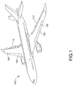
- FIG. 1 is a perspective view of an example aircraft 100 in which aspects of the present disclosure may be implemented.
- the example aircraft 100 of FIG. 1 includes a first wing 102 and a second wing 104.
- the first wing 102 and the second wing 104 each include a leading edge 106 and 108 and a trailing edge 110 and 112.
- FIG. 2 is a front view of the example aircraft 100 of FIG. 1 .
- the first wing 102 and the second wing 104 each include a first portion 200 and 202 (i.e., an inboard portion) and a second portion 204 and 206 (i.e., a tip portion).
- the second portion 204 of the first wing 102 and the second portion 206 of the second wing 104 are in a spread or flight position.
- the first wing 102 and the second wing 104 each provide a substantially continuous airfoil.
- the second portion 204 of the first wing 102 and/or the second portion 206 of the second wing 104 may be locked into the spread position.
- FIG. 3 illustrates the example aircraft 100 of FIGS. 1 and 2 in which the second portion 204 of the first wing 102 and the second portion 206 of the second wing 104 are in a folded position.
- a wingspan of the aircraft 100 is less than a wingspan of the aircraft 100 when the second portion 204 of the first wing 102 and the second portion 206 of the second wing 104 are in the spread position.
- FIG. 3 illustrates the example aircraft 100 of FIGS. 1 and 2 in which the second portion 204 of the first wing 102 and the second portion 206 of the second wing 104 are in a folded position.
- the second portion 204 of the first wing 102 and the second portion 206 of the second wing 104 are rotated upward relative to the first portions 200 and 202 such that the second portion 204 of the first wing 102 and the second portion 206 of the second wing 104 are oriented substantially vertically.
- the second portion 204 of the first wing 102 and the second portion 206 of the second wing 104 are rotated downward relative to the first portion 200 of the first wing 102 and the first portion 202 of the second wing 104, respectively, with the aircraft 100 viewed in the orientation of FIG. 2 .
- FIG. 4A is a diagram of a location of a folding wing tip system in a wing and FIG. 4B is a perspective top view diagram of selected elements of a folding wing tip system with the wing in a flight position in accordance with an illustrative embodiment. More specifically, FIG. 4A depicts a location for folding wing tip system 402 on aircraft 400. The illustration presents an area of a left wingtip of aircraft 400, such as shown for unfixed portion of aircraft 100 in FIG. 1 . An inverse arrangement may be applicable for a right wingtip of an aircraft 100.
- folding wing tip system 402 may include: fold actuator 404, centerline of rotation 406, second latch 408, second latch actuator 410, unfixed portion 412, and fixed portion 414.
- a first latch may be located at a forward edge of the folding wing tip system, but is not visible in this view.
- Unfixed portion 412 may be rotatably connected to fixed portion 414 about centerline of rotation 406 of unfixed portion 412.
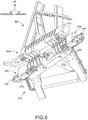
- FIG. 5 is a perspective view diagram of folding wing tip system with a wing in a folded position in accordance with an illustrative embodiment. More specifically, the side perspective viewpoint looks up and in toward fixed portion 516 of folding wing tip system 502 in the folded position. Folding wing tip system 502 is shown with unfixed portion 504 of the wing raised in folded position.
- Folding wing tip system 502 may include: unfixed portion 504, first latch 506, second latch 508, fold actuator 510, wingtip lug 512, inner lug 514, fixed portion 516, a first latch pin 518, and a second latch pin 520.
- Unfixed portion 504 may be in the folded position due to extension of fold actuator 510 while first latch pin 518 within first latch 506 and second latch pin 520 within second latch 508 may each be retracted by first latch actuator 522 and second latch actuator 524 respectively. In the open position, each latch actuator may retract its respective latch pin from engagement with the lugs 812, 814.
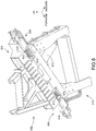
- FIG. 6 is a perspective view diagram of folding wing tip system with a wing in a flight position in accordance with an illustrative embodiment. More specifically, FIG. 6 presents a view looking up and in toward folding wing tip system 602 with unfixed portion 604 of a wing lowered in the flight position.
- First latch 606 and second latch 608 may each be in a closed position. Retraction of an extension member of fold actuator 610 may have moved unfixed portion 604 to the flight position.
- First latch pin 618 within first latch 606 and second latch pin 620 within second latch 608 may have been extended to closed positions by their respective latch actuators.
- the folding wing tip system may further include a plurality of latch pin assemblies 700, with a single latch pin assembly 700 illustrated in FIGS. 7 and 8 .
- the exemplary latch pin assembly 700 includes a latch pin 702 slidably supported on a latch pin piston 704 ( FIG. 8 ) for movement between latched and unlatched positions.
- the latch pin 702 defines an internal chamber that is divided by a head 706 of the piston into an extend chamber 708 and a retract chamber 710.
- the extend chamber 708 fluidly communicates with a latching hydraulic line 709 through a first channel 712 in the piston 704, while the retract chamber 710 fluidly communicates with an unlatching hydraulic line 711 through a second channel 714 in the piston 704.
- the latch pin 702 When hydraulic fluid is supplied to the extend chamber 708 through the latching hydraulic line 709, the latch pin 702 extends outwardly and through the wingtip lug(s) 512, and inner lug(s) 514 to the latched position as schematically shown in FIG. 8 , thereby to secure the unfixed portion 605 of the wing in the flight position. Conversely, when hydraulic fluid is supplied to the retract chamber 710 through the unlatching hydraulic line 711, the latch pin 702 retracts inwardly to withdraw from the wingtip lug(s) 512 and/or inner lug(s) 514 to the unlatched position, thereby to permit the unfixed portion 605 to rotate relative to the fixed portion of the wing.
- the latch pin assembly 700 further includes a first lock in the form of a mechanical lock to hold the latch pin 702 in the latched and prevent unintended retraction to the unlatched position.
- the first lock may include a lock cam 720 having a lock position in which the lock cam 720 engages a latch surface 716 of the latch pin 702 to mechanically hold the latch pin 702 in the latched position.
- the lock cam 720 may rotate to an unlock position in which the lock cam 720 is disengaged from the latch surface 716 as best shown in FIG. 11 .
- the first lock may further include a first lock actuator 722 configured to bias the lock cam 720 toward the lock position.
- the first lock actuator 722 includes a spring cartridge that includes a linkage arm 724 mechanically coupled to the lock cam 720 and a spring 726 engaging the linkage arm 724 , wherein the spring cartridge is oriented to provide a bias force that pushes the lock cam 720 toward the lock position.
- the latch pin assembly 700 may also include a second lock in the form of a hydraulic lock 730 which uses hydraulic fluid to prevent unintended retraction of the latch pin 702.
- the hydraulic lock 730 is provided as a check valve positioned in the latching hydraulic line 709 communicating between the extend chamber 708 and a hydraulic system provided on the aircraft.
- the check valve is oriented to have an initial state (as shown in FIGS. 8 and 10 ) which prevents fluid from exiting the extend chamber 708, thereby to hydraulically hold the latch pin 702 in the latched position.
- the check valve may be movable from the initial state to an open state (as best shown in FIG. 11 ) in which fluid is permitted to freely flow through the latching hydraulic line 709 into or out of the extend chamber 708.
- the check valve is provided as a zero leak check valve.
- the latch pin assembly 700 further includes an unlocking actuator 740 configured to move the lock cam 720 to the unlock position, thereby permitting the latch pin 702 to retract.
- the unlocking actuator 740 may be provided as a hydraulic actuator having a piston 742 with an arm 743 coupled to the lock cam 720 and a head disposed in a housing 744 defining an unlocking chamber 746 ( FIG. 8 ).
- the unlocking chamber 746 may fluidly communicate with the aircraft hydraulic system through an unlocking hydraulic line 748.
- the piston 742 When hydraulic fluid is supplied to the unlocking chamber 746, the piston 742 may move from a normal position to an actuated position.
- the piston 742 is commanded to the normal position when it is desired to hold the lock cam 720 in the locked position (thereby supporting the latch pin 702 in the latched position).
- the normal position of the piston 742 corresponds to an upper position of the piston 742 within the housing 744.
- the unlocking actuator 740 permits the bias force of the first lock actuator 722 to hold the lock cam 720 in the locked position.
- the actuated position of the piston 742 corresponds to a lower position of the piston 742 within the housing, such as the position shown in FIG. 11 .
- the piston 742 In the actuated position, the piston 742 generates an unlock force in a direction and with a magnitude that is sufficient to counteract the bias force of the first lock actuator 722, thereby to move the lock cam 720 to the unlock position.
- a sequencing valve 750 is mechanically coupled to the unlocking actuator 740 for sequencing operation of the first and second locks.
- the sequencing valve 750 fluidly communicates with the unlocking hydraulic line 748 and has a pilot line 752 fluidly communicating with the hydraulic lock 730.
- the sequencing valve has a blocking state (as shown in FIG. 8 ) when the hydraulic actuator 740 is in the normal position, in which fluid flow through the pilot line 752 is blocked.
- the hydraulic actuator 740 moves to the actuated position it also moves the sequencing valve 750 to a free state, in which fluid flow is permitted through the pilot line 752.
- a valve 754 may be provided in the latching hydraulic line 709 to relieve fluid pressure due to thermal expansion.
- the thermal relief valve 754 is provided in parallel with the hydraulic lock 730.
- the latch pin assembly 700 may include an inhibit assembly 760 to provide for further sequencing of operations during actuation of the latch pin 702 and/or lock cam 720.
- the inhibit assembly may include an in inhibit pin 762 and an inhibit spring 764.
- the inhibit pin 762 has a tip that is spaced from the lock cam 720 when the lock cam is in the locked position. As the lock cam 720 rotates from the locked position, it will engage the inhibit pin 762 to permit further sequencing of operations, as described more fully below.
- the lock cam 720 includes a boss 721 ( FIG. 7 ) configured to engage the inhibit pin 762 at the desired point during rotation of the lock cam 720.
- FIG. 9 is a schematic diagram showing the hydraulic connections between four latch pin assemblies 700 and the aircraft hydraulic system 900, which includes a supply line 902 and a return line 904.
- An isolation valve 906 is disposed in the supply and return lines 902, 904 between the aircraft hydraulic system 900 and the latch pin assemblies 700.
- a latch pin unlock valve 910 is connected to both the supply and return lines 902, 904 on one side and the unlocking hydraulic line 748 on the other side.
- a latch pin actuation valve 912 is connected to both the supply and return lines 902, 904 on one side and the latching and unlatching hydraulic lines 709, 711 on the other side.
- a fold motor 920 operably coupled to the fold actuator 510 by an angle gearbox 924.
- FIG. 9 illustrates a lock cam position sensor 930 associated with each of the latch pin actuators for providing feedback regarding a position of each lock cam 720.
- the aircraft hydraulic system 900 may be configured to place the latch pin 702 in the latched position and the lock cam 720 in the locked position, as shown in FIG. 10 .
- the latch pin 702 initially may be placed in the latched position. This may be accomplished by placing the isolation valve 906 in an open position (opposite the position shown in FIG. 9 ), the latch pin unlock valve 910 in a closed position (as shown in FIG. 9 ), and the latch pin actuation valve 912 in an extend position (as shown in FIG. 9 ), so that the unlocking hydraulic line 748 communicates with the return line 904, the latching hydraulic line 709 fluidly communicates with the supply line 902, and the unlatching hydraulic line 711 fluidly communicates with the return line 904.
- the isolation valve 906 is moved to the open position (opposite the position shown in FIG. 9 ) and the latch pin unlock valve 910 is moved to an open position (opposite the position shown in FIG. 9 ), so that the supply line 902 fluidly communicates with the unlocking hydraulic line 748. Hydraulic fluid will flow to the unlocking actuator 740 and move it to the actuated position, thereby generating sufficient unlocking force to overcome the bias force of the first lock actuator 722 and rotate the lock cam 720 to the unlocked position shown in FIG. 11 .
- the hydraulic lock 730 will still prevent retraction of the latch pin 702 from the latched position.
- the sequencing valve 750 is moved to the open position to permit hydraulic fluid to flow through the pilot line 752 to the hydraulic lock 730, thereby moving the hydraulic lock 730 to the open state as shown in FIG. 11 .
- the latch pin actuation valve 912 may be moved to a retract position (opposite the position shown in FIG.
- the lock cam 720 may be supported in an "unlocked, inhibited" position that is intermediate the locked position and the unlocked position. That is, when the unlocking actuator 740 moves to the actuated position, the lock cam 720 may rotate from the locked position towards the unlocked position until the inhibit pin 762 engages the boss 721 of the lock cam 720. The lock cam 720 may be held in this intermediate position until the hydraulic lock 730 is disabled and the latch pin 702 is retracted to the unlatched position, as movement of the latch pin 702 will overcome the force of the inhibit spring 764 to retract the inhibit pin 762 and allow the lock cam 720 to rotate fully to the unlocked position.
- the latch pin 702 may engage the inhibit pin 762 to move the inhibit pin 762 out of the path of the lock cam 720, thereby permitting the latch pin 702 to fully retract to the unlatched position.
- the fold motor 920 may be operated to cause the fold actuator 510 to move the wing tip to the folded position, after which the system may again be isolated by moving the isolation valve 906 back to the isolation position.
- the exemplary latch pin assembly 700 further may be configured to facilitate identification of a mechanical failure of the lock cam 720. Repeated actuation of the latch pin 702 may wear down portions of the lock cam 720 that contact the latch pin 702. This wear on the lock cam 720 may remove an area of material that would normally engage the latch pin 702 when the lock cam 720 is in the locking position, thereby preventing the lock cam 720 from performing its primary function of locking the latch pin 702 in the latched position. It would be advantageous, therefore, for the lock pin actuator to facilitate identification of such wear to expedite any needed repair and minimize aircraft downtime.
- a portion of the lock cam 720 used to lock the latch pin 702 in the latched position is fully disposed in the travel path of the latch pin 702.
- the lock cam 720 includes a recess 770 that creates a localized area of reduced thickness in the lock cam 720.
- the recess 770 is formed adjacent a contact portion 772 of the lock cam 720 that engages the latch pin 702 when the lock cam 720 is in the locked position.
- the lock cam 720 will not transfer rotation applied to a first portion of the lock cam 720 located on one side of the recess 770 to a second portion of the lock cam 720 located on the opposite side of the recess 770. Accordingly, torque provided by the unlocking actuator 740, which is applied to a first portion of the lock cam 720 located on a first side of the recess 770, will not cause a resultant rotation of a second portion of the lock cam 720 located on an opposite side of the recess 770.
- the lock cam position sensor 930 may be positioned to detect the position of the second portion of the lock cam 720, and therefore a mechanical failure of the lock cam 720 may be quickly identified by comparing the command input to the lock cam position feedback.
Landscapes
- Engineering & Computer Science (AREA)
- Mechanical Engineering (AREA)
- Remote Sensing (AREA)
- Aviation & Aerospace Engineering (AREA)
- Physics & Mathematics (AREA)
- Fluid Mechanics (AREA)
- General Engineering & Computer Science (AREA)
- Actuator (AREA)
- Fluid-Pressure Circuits (AREA)
Claims (10)
- Verriegelungsbolzenanordnung (700) für ein Luftfahrzeug, das eine Hydraulikfluidquelle aufweist, wobei die Verriegelungsbolzenanordnung (700) aufweist:einen Kolben (704), der einen Kolbenkopf (706) umfasst;einen Verriegelungsbolzen (702), der den Kolbenkopf (706) umgibt und der eine Innenkammer definiert, wobei der Kolbenkopf (706) die Innenkammer in eine Ausfahrkammer (708) und eine Rückzugskammer (710) trennt, wobei der Verriegelungsbolzen (702) eine Verriegelungsfläche (716) umfasst;eine Verriegelungshydraulikleitung (709), die zum fluidischen Kommunizieren zwischen der Ausfahrkammer (708) und der Hydraulikfluidquelle angepasst ist;eine Entriegelungshydraulikleitung (711), die zum fluidischen Kommunizieren zwischen der Rückzugskammer (710) und der Hydraulikfluidquelle angepasst ist;eine erste Verriegelung, die einen Verriegelungsnocken (720) aufweist, der zwischen einer Verriegelungsposition, in welcher der Verriegelungsnocken (720) im Eingriff mit der Verriegelungsfläche (716) des Verriegelungsbolzens (702) ist, und einer Entriegelungsposition beweglich ist, in welcher der Verriegelungsnocken (720) außer Eingriff mit der Verriegelungsfläche (716) des Verriegelungsbolzens (702) ist;wobei die erste Verriegelung ferner einen ersten Verriegelungsaktuator (722) aufweist, der mechanisch an den Verriegelungsnocken (720) gekoppelt ist und der zum Bereitstellen einer Vorspannkraft eingerichtet ist, die den Verriegelungsnocken (720) in Richtung der Verriegelungsposition drückt;einen Entriegelungsaktuator (740), der betriebsfähig an den Verriegelungsnocken (720) gekoppelt ist und der zum Bereitstellen einer Entriegelungskraft eingerichtet ist, die der Vorspannkraft des ersten Verriegelungsaktuators (722) entgegenwirkt;wobei der Entriegelungsaktuator (740) einen Hydraulikaktuator aufweist und wobei die Verriegelungsbolzenanordnung (700) ferner eine Entriegelungshydraulikleitung (748) umfasst, die zum fluidischen Kommunizieren zwischen dem Hydraulikaktuator und der Hydraulikfluidquelle angepasst ist,wobei die Verriegelungsbolzenanordnung (700) ferner eine zweite Verriegelung aufweist, die eine Hydraulikverriegelung (730) umfasst, die in der Verriegelungshydraulikleitung (709) angeordnet ist und die einen anfänglichen Zustand, in welchem eine Fluidströmung durch die Verriegelungshydraulikleitung (709) blockiert ist, und einen offenen Zustand aufweist, in welchem eine Fluidströmung durch die Verriegelungshydraulikleitung (709) zugelassen wird, und wobei die Verriegelungsbolzenanordnung (700) ferner ein Folgeventil (750) aufweist, das mechanisch an den Hydraulikaktuator gekoppelt ist und fluidisch an die Hydraulikverriegelung (730) durch eine Steuerleitung (752) gekoppelt ist, wobei das Folgeventil (750) zwischen einem Blockadezustand, wenn sich der Hydraulikaktuator in der normalen Position befindet, um eine Fluidströmung durch die Steuerleitung (752) zu verhindern, und einem freien Zustand beweglich ist, wenn sich der Hydraulikaktuator in der betätigten Position befindet, um eine Fluidströmung durch die Steuerleitung (752) zuzulassen.
- Verriegelungsbolzenanordnung nach Anspruch 1, wobei der Hydraulikaktuator des Entriegelungsaktuators (740) zwischen einer normalen Position, in welcher die Entriegelungskraft geringer als die Vorspannkraft ist, und einer betätigten Position beweglich ist, in welcher die Entriegelungskraft größer als die Vorspannkraft ist.
- Verriegelungsbolzenanordnung nach Anspruch 1, wobei die Hydraulikverriegelung (730) eingerichtet ist, sich in den offenen Zustand zu bewegen, wenn ein Hydraulikfluid durch die Steuerleitung (752) fließt.
- Verriegelungsbolzenanordnung nach Anspruch 1, Anspruch 2 oder Anspruch 3, wobei der erste Verriegelungsaktuator (722) eine Feder (726) aufweist.
- Verriegelungsbolzenanordnung nach Anspruch 1, Anspruch 2, Anspruch 3 oder Anspruch 4, wobei die Hydraulikverriegelung (730) ein Kontrollventil aufweist.
- Luftfahrzeug, das die Verriegelungsbolzenanordnung nach Anspruch 1, Anspruch 2, Anspruch 3, Anspruch 4 oder Anspruch 5 aufweist, wobei das Luftfahrzeug (100) ferner einen fixierten Flügelabschnitt, der einen ersten Satz von Nasen umfasst, und einen nicht fixierten Flügelabschnitt aufweist, der einen zweiten Satz von Nasen umfasst, und wobei der Verriegelungsbolzen zum Einführen durch die ersten und zweiten Sätze von Nasen dimensioniert ist.
- Verfahren zum Sichern eines Verriegelungsbolzens (702) in einer verriegelten Position für ein Luftfahrzeug (100) mit einer Hydraulikfluidquelle, wobei der Verriegelungsbolzen (702) in einer Verriegelungsbolzenanordnung (700) gemäß einem der Ansprüche 1 bis 5 vorgesehen ist oder in einer Verriegelungsbolzenanordnung eines Luftfahrzeugs nach Anspruch 6 vorgesehen ist, wobei das Verfahren aufweist:mechanisches Verriegeln des Verriegelungsbolzens (702) in der verriegelten Position durch Ineingriffbringen eines Verriegelungsnockens (720) mit einer Vorspannkraft zum Bewegen des Verriegelungsnockens (720) in eine Verriegelungsposition, wobei der Verriegelungsnocken (720) in der verriegelten Position mechanisch in Eingriff mit dem Verriegelungsbolzen (702) ist; undhydraulisches Verriegeln des Verriegelungsbolzens (702) in der verriegelten Position, indem eine Fluidströmung durch eine Verriegelungshydraulikleitung (709) verhindert wird, die fluidisch zwischen der Hydraulikfluidquelle und einer Rückzugskammer des Verriegelungsbolzens (702) kommuniziert.
- Verfahren nach Anspruch 7, wobei ein mechanisches Verriegeln des Verriegelungsbolzens (702) ein Ineingriffbringen des Verriegelungsnockens (702) mit einer ersten Verriegelung aufweist, die zum Erzeugen der Vorspannkraft eingerichtet ist.
- Verfahren nach Anspruch 8 oder nach Anspruch 9, wobei ein Steuerventil in der Verriegelungshydraulikleitung (709) angeordnet ist und einen anfänglichen Zustand, in welchem eine Fluidströmung durch die Verriegelungshydraulikleitung (709) blockiert ist, und einen offenen Zustand aufweist, in welchem eine Fluidströmung durch die Verriegelungshydraulikleitung (709) zugelassen wird, und wobei ein hydraulisches Verriegeln des Verriegelungsbolzens (702) ein Versetzen des Steuerventils in den anfänglichen Zustand aufweist.
- Verfahren nach Anspruch 8, Anspruch 9 oder Anspruch 10, wobei der Verriegelungsbolzen (702) eine Verriegelungsbolzenfläche (716) umfasst und wobei ein mechanisches Verriegeln des Verriegelungsbolzens (702) ein mechanisches Ineingriffbringen des Verriegelungsnockens (720) mit der Verriegelungsbolzenfläche (716) aufweist.
Priority Applications (1)
| Application Number | Priority Date | Filing Date | Title |
|---|---|---|---|
| EP20158227.7A EP3674206B1 (de) | 2015-01-19 | 2016-01-08 | Verriegelungsstiftanordnung für klappflügelspitzensystem |
Applications Claiming Priority (2)
| Application Number | Priority Date | Filing Date | Title |
|---|---|---|---|
| US201562105127P | 2015-01-19 | 2015-01-19 | |
| US14/824,858 US9914524B2 (en) | 2015-01-19 | 2015-08-12 | Latch pin assembly for folding wing tip system |
Related Child Applications (1)
| Application Number | Title | Priority Date | Filing Date |
|---|---|---|---|
| EP20158227.7A Division EP3674206B1 (de) | 2015-01-19 | 2016-01-08 | Verriegelungsstiftanordnung für klappflügelspitzensystem |
Publications (2)
| Publication Number | Publication Date |
|---|---|
| EP3045388A1 EP3045388A1 (de) | 2016-07-20 |
| EP3045388B1 true EP3045388B1 (de) | 2020-03-04 |
Family
ID=55070947
Family Applications (2)
| Application Number | Title | Priority Date | Filing Date |
|---|---|---|---|
| EP16150592.0A Active EP3045388B1 (de) | 2015-01-19 | 2016-01-08 | Verriegelungsstiftanordnung für klappflügelspitzensystem |
| EP20158227.7A Active EP3674206B1 (de) | 2015-01-19 | 2016-01-08 | Verriegelungsstiftanordnung für klappflügelspitzensystem |
Family Applications After (1)
| Application Number | Title | Priority Date | Filing Date |
|---|---|---|---|
| EP20158227.7A Active EP3674206B1 (de) | 2015-01-19 | 2016-01-08 | Verriegelungsstiftanordnung für klappflügelspitzensystem |
Country Status (5)
| Country | Link |
|---|---|
| US (2) | US9914524B2 (de) |
| EP (2) | EP3045388B1 (de) |
| JP (1) | JP7014503B2 (de) |
| CN (1) | CN105799913B (de) |
| CA (1) | CA2918094C (de) |
Families Citing this family (27)
| Publication number | Priority date | Publication date | Assignee | Title |
|---|---|---|---|---|
| US10106244B2 (en) * | 2014-11-07 | 2018-10-23 | The Boeing Company | Backup system |
| US9873502B2 (en) | 2016-01-05 | 2018-01-23 | The Boeing Company | Controlling airloads on aircraft folding wing tips |
| US9919809B2 (en) * | 2016-06-07 | 2018-03-20 | The Boeing Company | Folding wing system |
| EP3309057A1 (de) * | 2016-10-11 | 2018-04-18 | Airbus Operations GmbH | Flugzeugflügel mit nach oben klappbarer flügelspitzenvorrichtung |
| US10808808B2 (en) | 2017-05-05 | 2020-10-20 | Sierra Nevada Corporation | Expanding pin assembly controlled by actuator for locking and unlocking mechanical joint |
| EP3403922A1 (de) * | 2017-05-18 | 2018-11-21 | Airbus Operations GmbH | Flügelanordnung für ein flugzeug |
| US10370084B2 (en) * | 2017-07-21 | 2019-08-06 | The Boeing Company | Methods and apparatus to adjust folding wing tips |
| EP3486162B1 (de) * | 2017-11-17 | 2020-07-01 | Airbus Operations GmbH | Verfahren zum betreiben eines flügels für ein flugzeug mit einem klappbaren flügelspitzenabschnitt |
| EP3492370B1 (de) * | 2017-11-17 | 2020-07-15 | Airbus Operations GmbH | Verfahren zum testen des betriebs einer arretiereinheit zum verriegeln eines faltbaren flügelspitzenabschnitts in einer ausgefahrenen position |
| EP3486163B1 (de) * | 2017-11-17 | 2020-02-26 | Airbus Operations GmbH | Betätigungssystem zum betätigen eines klappbaren flügelendenabschnitts eines flügels für ein flugzeug |
| US11345459B2 (en) * | 2018-05-28 | 2022-05-31 | Airbus Operations Gmbh | Wing for an aircraft |
| EP3597940A1 (de) * | 2018-07-20 | 2020-01-22 | Goodrich Actuation Systems Limited | Verriegelungsmechanismus |
| US11066148B2 (en) | 2018-08-06 | 2021-07-20 | The Boeing Company | Folding wing hinge, aircraft and method therefor |
| US11686330B2 (en) * | 2018-09-20 | 2023-06-27 | The Boeing Company | Manufacture and process for inhibiting wear in a latch system |
| US11485474B2 (en) | 2019-02-01 | 2022-11-01 | The Boeing Company | Foldable aircraft wings |
| GB2582668B (en) | 2019-03-29 | 2021-03-24 | Airbus Operations Ltd | An aircraft wing with wing tip device |
| US11254412B2 (en) | 2019-03-29 | 2022-02-22 | The Boeing Company | Foldable raked wing tips having aerodynamic devices |
| US11518500B2 (en) | 2019-05-03 | 2022-12-06 | The Boeing Company | Aircraft having foldable wings |
| WO2020260394A1 (en) * | 2019-06-28 | 2020-12-30 | Airbus Operations Gmbh | Wing for an aircraft |
| CN111824399B (zh) * | 2020-06-05 | 2023-06-13 | 贵州新安航空机械有限责任公司 | 一种航空用机轮左右同步上锁机构 |
| CN112722237B (zh) * | 2021-02-20 | 2023-08-25 | 江西经济管理干部学院 | 一种航空飞行器翼梢小翼 |
| US12552550B2 (en) | 2023-07-24 | 2026-02-17 | The Boeing Company | System and method to detect anomalous wingtip extension for a folding wing tip aircraft |
| EP4497675A1 (de) * | 2023-07-24 | 2025-01-29 | The Boeing Company | System und verfahren zur erkennung einer anomalen flügelspitzenerweiterung für ein flugzeug mit klappflügelspitze |
| US12522376B2 (en) | 2023-07-24 | 2026-01-13 | The Boeing Company | System and method to detect anomalous wingtip extension for a folding wing tip aircraft |
| GB2643499A (en) * | 2024-07-31 | 2026-02-25 | Airbus Operations Ltd | Latch |
| EP4725831A1 (de) * | 2024-10-14 | 2026-04-15 | Goodrich Actuation Systems Limited | Betätigungssystem für klappbare flügelspitzen |
| CN119749837A (zh) * | 2025-01-08 | 2025-04-04 | 中国航空工业集团公司沈阳飞机设计研究所 | 一种机翼折叠展平机构驱动系统及其操控方法 |
Family Cites Families (19)
| Publication number | Priority date | Publication date | Assignee | Title |
|---|---|---|---|---|
| US5310138A (en) * | 1991-12-30 | 1994-05-10 | Alliedsignal Inc. | Wing fold actuator system for aircraft |
| US5427329A (en) | 1992-01-30 | 1995-06-27 | The Boeing Company | Locking hydraulic latch pin actuator |
| US5201479A (en) | 1992-01-30 | 1993-04-13 | The Boeing Company | Self-monitoring latch pin lock for folding wing aircraft |
| US5452643A (en) * | 1992-01-30 | 1995-09-26 | The Boeing Company | Hydraulic power drive unit |
| US5379969A (en) | 1992-01-30 | 1995-01-10 | The Boeing Company | Hydraulic actuator with mechanical lock and installation |
| US5381986A (en) | 1992-01-30 | 1995-01-17 | The Boeing Company | Folding wing-tip system |
| US5350135A (en) | 1992-01-30 | 1994-09-27 | The Boeing Company | Latch pin inhibitor for folding wing-tip aircraft |
| DE10202607C1 (de) | 2002-01-24 | 2003-07-31 | Hydac Fluidtechnik Gmbh | Steuervorrichtung, insbesondere für den Einsatz bei hydraulisch arbeitenden Hubeinrichtungen |
| US7445180B2 (en) | 2006-10-02 | 2008-11-04 | The Boeing Company | Actuation system for tail section of aircraft |
| US9499252B2 (en) | 2011-10-01 | 2016-11-22 | The Boeing Company | Wing fold controller |
| US9211946B2 (en) | 2011-10-01 | 2015-12-15 | The Boeing Company | Wing fold system with latch pins through multiple mating lugs |
| US9290260B2 (en) * | 2011-10-01 | 2016-03-22 | The Boeing Company | Wing fold controller |
| US10538307B2 (en) | 2011-10-01 | 2020-01-21 | The Boeing Company | Hinged raked wing tip |
| US8733692B2 (en) | 2012-06-11 | 2014-05-27 | The Boeing Company | Latching apparatus and methods |
| US8708286B2 (en) | 2012-06-21 | 2014-04-29 | The Boeing Company | Swing tip assembly rotation joint |
| US9803425B2 (en) | 2012-09-14 | 2017-10-31 | Halliburton Energy Services, Inc. | Rotary steerable drilling system |
| US9914523B2 (en) | 2012-10-30 | 2018-03-13 | The Boeing Company | Wing hinge assembly including hinged torque boxes |
| US9291176B2 (en) | 2013-01-30 | 2016-03-22 | Messier-Dowty Inc. | Locking mechanism for locking an actuator |
| US8894004B1 (en) * | 2013-06-11 | 2014-11-25 | The United States Of America As Represented By The Secretary Of The Navy | Folding articulating wing mechanism |
-
2015
- 2015-08-12 US US14/824,858 patent/US9914524B2/en active Active
-
2016
- 2016-01-08 EP EP16150592.0A patent/EP3045388B1/de active Active
- 2016-01-08 EP EP20158227.7A patent/EP3674206B1/de active Active
- 2016-01-13 JP JP2016004030A patent/JP7014503B2/ja active Active
- 2016-01-13 CN CN201610023551.9A patent/CN105799913B/zh active Active
- 2016-01-18 CA CA2918094A patent/CA2918094C/en active Active
-
2018
- 2018-01-26 US US15/881,248 patent/US10173766B2/en active Active
Non-Patent Citations (1)
| Title |
|---|
| None * |
Also Published As
| Publication number | Publication date |
|---|---|
| JP2016147659A (ja) | 2016-08-18 |
| CN105799913B (zh) | 2020-06-19 |
| EP3045388A1 (de) | 2016-07-20 |
| EP3674206A1 (de) | 2020-07-01 |
| CA2918094C (en) | 2020-07-14 |
| US20160207608A1 (en) | 2016-07-21 |
| CA2918094A1 (en) | 2016-07-19 |
| EP3674206B1 (de) | 2022-08-24 |
| US9914524B2 (en) | 2018-03-13 |
| US20180148159A1 (en) | 2018-05-31 |
| US10173766B2 (en) | 2019-01-08 |
| JP7014503B2 (ja) | 2022-02-01 |
| CN105799913A (zh) | 2016-07-27 |
Similar Documents
| Publication | Publication Date | Title |
|---|---|---|
| US10173766B2 (en) | Latch pin assembly | |
| CN107472510B (zh) | 栓销致动器及其故障确定方法、折叠翼系统及曲柄臂组件 | |
| EP2509857B1 (de) | Steuerflächenanordnung | |
| US6799739B1 (en) | Aircraft control surface drive system and associated methods | |
| US8418958B2 (en) | Landing gear actuation control system | |
| AU2011229883B2 (en) | Semi-levered landing gear and associated method | |
| EP3414445B1 (de) | Betätigung eines schubumkehrsystems | |
| US9211946B2 (en) | Wing fold system with latch pins through multiple mating lugs | |
| EP3560819B1 (de) | Verbesserter sekundärverriegelungsmechanismus | |
| US9783296B2 (en) | Aircraft store deployment system with improved safety of arming and releasing stores | |
| US8919692B2 (en) | Proximity sensor valve and lock system using same | |
| US10543898B2 (en) | Dual-purpose locking and folding arrangement for an aircraft wing tip device | |
| US20150167702A1 (en) | Actuator assemblies | |
| CN105102828B (zh) | 锁定驱动器的锁定机构 | |
| EP3931434B1 (de) | Verfahrbares fingerschloss für einen aktuator | |
| EP3418182B1 (de) | Flügelfaltsystem mit durch mehrere ineinandergreifende laschen geführten verrieglungsstiften | |
| EP4176169B1 (de) | Hydraulisches schloss einer synchronisierung | |
| EP3575206A1 (de) | System zum antrieb einer klappenanordnung zwischen einer eingezogenen position und einer erweiterten position | |
| US11136940B2 (en) | Hydraulic thrust reverser actuation system | |
| EP4644237A1 (de) | Fahrwerk ausfahr- und einfahrsystem |
Legal Events
| Date | Code | Title | Description |
|---|---|---|---|
| PUAI | Public reference made under article 153(3) epc to a published international application that has entered the european phase |
Free format text: ORIGINAL CODE: 0009012 |
|
| AK | Designated contracting states |
Kind code of ref document: A1 Designated state(s): AL AT BE BG CH CY CZ DE DK EE ES FI FR GB GR HR HU IE IS IT LI LT LU LV MC MK MT NL NO PL PT RO RS SE SI SK SM TR |
|
| AX | Request for extension of the european patent |
Extension state: BA ME |
|
| STAA | Information on the status of an ep patent application or granted ep patent |
Free format text: STATUS: REQUEST FOR EXAMINATION WAS MADE |
|
| 17P | Request for examination filed |
Effective date: 20170111 |
|
| RBV | Designated contracting states (corrected) |
Designated state(s): AL AT BE BG CH CY CZ DE DK EE ES FI FR GB GR HR HU IE IS IT LI LT LU LV MC MK MT NL NO PL PT RO RS SE SI SK SM TR |
|
| STAA | Information on the status of an ep patent application or granted ep patent |
Free format text: STATUS: EXAMINATION IS IN PROGRESS |
|
| 17Q | First examination report despatched |
Effective date: 20180620 |
|
| REG | Reference to a national code |
Ref country code: DE Ref legal event code: R079 Ref document number: 602016030874 Country of ref document: DE Free format text: PREVIOUS MAIN CLASS: B64C0003560000 Ipc: B64C0023060000 |
|
| GRAP | Despatch of communication of intention to grant a patent |
Free format text: ORIGINAL CODE: EPIDOSNIGR1 |
|
| STAA | Information on the status of an ep patent application or granted ep patent |
Free format text: STATUS: GRANT OF PATENT IS INTENDED |
|
| RIC1 | Information provided on ipc code assigned before grant |
Ipc: F15B 13/01 20060101ALI20181008BHEP Ipc: B64C 23/06 20060101AFI20181008BHEP Ipc: F15B 11/00 20060101ALI20181008BHEP Ipc: F15B 15/26 20060101ALI20181008BHEP Ipc: B64C 3/56 20060101ALI20181008BHEP |
|
| INTG | Intention to grant announced |
Effective date: 20181102 |
|
| GRAJ | Information related to disapproval of communication of intention to grant by the applicant or resumption of examination proceedings by the epo deleted |
Free format text: ORIGINAL CODE: EPIDOSDIGR1 |
|
| STAA | Information on the status of an ep patent application or granted ep patent |
Free format text: STATUS: EXAMINATION IS IN PROGRESS |
|
| INTC | Intention to grant announced (deleted) | ||
| GRAP | Despatch of communication of intention to grant a patent |
Free format text: ORIGINAL CODE: EPIDOSNIGR1 |
|
| STAA | Information on the status of an ep patent application or granted ep patent |
Free format text: STATUS: GRANT OF PATENT IS INTENDED |
|
| INTG | Intention to grant announced |
Effective date: 20190325 |
|
| GRAJ | Information related to disapproval of communication of intention to grant by the applicant or resumption of examination proceedings by the epo deleted |
Free format text: ORIGINAL CODE: EPIDOSDIGR1 |
|
| STAA | Information on the status of an ep patent application or granted ep patent |
Free format text: STATUS: EXAMINATION IS IN PROGRESS |
|
| INTC | Intention to grant announced (deleted) | ||
| GRAP | Despatch of communication of intention to grant a patent |
Free format text: ORIGINAL CODE: EPIDOSNIGR1 |
|
| STAA | Information on the status of an ep patent application or granted ep patent |
Free format text: STATUS: GRANT OF PATENT IS INTENDED |
|
| INTG | Intention to grant announced |
Effective date: 20190729 |
|
| GRAS | Grant fee paid |
Free format text: ORIGINAL CODE: EPIDOSNIGR3 |
|
| GRAA | (expected) grant |
Free format text: ORIGINAL CODE: 0009210 |
|
| STAA | Information on the status of an ep patent application or granted ep patent |
Free format text: STATUS: THE PATENT HAS BEEN GRANTED |
|
| AK | Designated contracting states |
Kind code of ref document: B1 Designated state(s): AL AT BE BG CH CY CZ DE DK EE ES FI FR GB GR HR HU IE IS IT LI LT LU LV MC MK MT NL NO PL PT RO RS SE SI SK SM TR |
|
| REG | Reference to a national code |
Ref country code: GB Ref legal event code: FG4D |
|
| REG | Reference to a national code |
Ref country code: CH Ref legal event code: EP |
|
| REG | Reference to a national code |
Ref country code: AT Ref legal event code: REF Ref document number: 1240079 Country of ref document: AT Kind code of ref document: T Effective date: 20200315 |
|
| REG | Reference to a national code |
Ref country code: DE Ref legal event code: R096 Ref document number: 602016030874 Country of ref document: DE |
|
| REG | Reference to a national code |
Ref country code: IE Ref legal event code: FG4D |
|
| PG25 | Lapsed in a contracting state [announced via postgrant information from national office to epo] |
Ref country code: FI Free format text: LAPSE BECAUSE OF FAILURE TO SUBMIT A TRANSLATION OF THE DESCRIPTION OR TO PAY THE FEE WITHIN THE PRESCRIBED TIME-LIMIT Effective date: 20200304 Ref country code: RS Free format text: LAPSE BECAUSE OF FAILURE TO SUBMIT A TRANSLATION OF THE DESCRIPTION OR TO PAY THE FEE WITHIN THE PRESCRIBED TIME-LIMIT Effective date: 20200304 Ref country code: NO Free format text: LAPSE BECAUSE OF FAILURE TO SUBMIT A TRANSLATION OF THE DESCRIPTION OR TO PAY THE FEE WITHIN THE PRESCRIBED TIME-LIMIT Effective date: 20200604 |
|
| REG | Reference to a national code |
Ref country code: NL Ref legal event code: MP Effective date: 20200304 |
|
| PG25 | Lapsed in a contracting state [announced via postgrant information from national office to epo] |
Ref country code: HR Free format text: LAPSE BECAUSE OF FAILURE TO SUBMIT A TRANSLATION OF THE DESCRIPTION OR TO PAY THE FEE WITHIN THE PRESCRIBED TIME-LIMIT Effective date: 20200304 Ref country code: LV Free format text: LAPSE BECAUSE OF FAILURE TO SUBMIT A TRANSLATION OF THE DESCRIPTION OR TO PAY THE FEE WITHIN THE PRESCRIBED TIME-LIMIT Effective date: 20200304 Ref country code: SE Free format text: LAPSE BECAUSE OF FAILURE TO SUBMIT A TRANSLATION OF THE DESCRIPTION OR TO PAY THE FEE WITHIN THE PRESCRIBED TIME-LIMIT Effective date: 20200304 Ref country code: GR Free format text: LAPSE BECAUSE OF FAILURE TO SUBMIT A TRANSLATION OF THE DESCRIPTION OR TO PAY THE FEE WITHIN THE PRESCRIBED TIME-LIMIT Effective date: 20200605 Ref country code: BG Free format text: LAPSE BECAUSE OF FAILURE TO SUBMIT A TRANSLATION OF THE DESCRIPTION OR TO PAY THE FEE WITHIN THE PRESCRIBED TIME-LIMIT Effective date: 20200604 |
|
| REG | Reference to a national code |
Ref country code: LT Ref legal event code: MG4D |
|
| PG25 | Lapsed in a contracting state [announced via postgrant information from national office to epo] |
Ref country code: NL Free format text: LAPSE BECAUSE OF FAILURE TO SUBMIT A TRANSLATION OF THE DESCRIPTION OR TO PAY THE FEE WITHIN THE PRESCRIBED TIME-LIMIT Effective date: 20200304 |
|
| PG25 | Lapsed in a contracting state [announced via postgrant information from national office to epo] |
Ref country code: EE Free format text: LAPSE BECAUSE OF FAILURE TO SUBMIT A TRANSLATION OF THE DESCRIPTION OR TO PAY THE FEE WITHIN THE PRESCRIBED TIME-LIMIT Effective date: 20200304 Ref country code: RO Free format text: LAPSE BECAUSE OF FAILURE TO SUBMIT A TRANSLATION OF THE DESCRIPTION OR TO PAY THE FEE WITHIN THE PRESCRIBED TIME-LIMIT Effective date: 20200304 Ref country code: CZ Free format text: LAPSE BECAUSE OF FAILURE TO SUBMIT A TRANSLATION OF THE DESCRIPTION OR TO PAY THE FEE WITHIN THE PRESCRIBED TIME-LIMIT Effective date: 20200304 Ref country code: LT Free format text: LAPSE BECAUSE OF FAILURE TO SUBMIT A TRANSLATION OF THE DESCRIPTION OR TO PAY THE FEE WITHIN THE PRESCRIBED TIME-LIMIT Effective date: 20200304 Ref country code: SM Free format text: LAPSE BECAUSE OF FAILURE TO SUBMIT A TRANSLATION OF THE DESCRIPTION OR TO PAY THE FEE WITHIN THE PRESCRIBED TIME-LIMIT Effective date: 20200304 Ref country code: SK Free format text: LAPSE BECAUSE OF FAILURE TO SUBMIT A TRANSLATION OF THE DESCRIPTION OR TO PAY THE FEE WITHIN THE PRESCRIBED TIME-LIMIT Effective date: 20200304 Ref country code: IS Free format text: LAPSE BECAUSE OF FAILURE TO SUBMIT A TRANSLATION OF THE DESCRIPTION OR TO PAY THE FEE WITHIN THE PRESCRIBED TIME-LIMIT Effective date: 20200704 Ref country code: ES Free format text: LAPSE BECAUSE OF FAILURE TO SUBMIT A TRANSLATION OF THE DESCRIPTION OR TO PAY THE FEE WITHIN THE PRESCRIBED TIME-LIMIT Effective date: 20200304 Ref country code: PT Free format text: LAPSE BECAUSE OF FAILURE TO SUBMIT A TRANSLATION OF THE DESCRIPTION OR TO PAY THE FEE WITHIN THE PRESCRIBED TIME-LIMIT Effective date: 20200729 |
|
| REG | Reference to a national code |
Ref country code: AT Ref legal event code: MK05 Ref document number: 1240079 Country of ref document: AT Kind code of ref document: T Effective date: 20200304 |
|
| REG | Reference to a national code |
Ref country code: DE Ref legal event code: R097 Ref document number: 602016030874 Country of ref document: DE |
|
| PLBE | No opposition filed within time limit |
Free format text: ORIGINAL CODE: 0009261 |
|
| STAA | Information on the status of an ep patent application or granted ep patent |
Free format text: STATUS: NO OPPOSITION FILED WITHIN TIME LIMIT |
|
| PG25 | Lapsed in a contracting state [announced via postgrant information from national office to epo] |
Ref country code: AT Free format text: LAPSE BECAUSE OF FAILURE TO SUBMIT A TRANSLATION OF THE DESCRIPTION OR TO PAY THE FEE WITHIN THE PRESCRIBED TIME-LIMIT Effective date: 20200304 Ref country code: DK Free format text: LAPSE BECAUSE OF FAILURE TO SUBMIT A TRANSLATION OF THE DESCRIPTION OR TO PAY THE FEE WITHIN THE PRESCRIBED TIME-LIMIT Effective date: 20200304 Ref country code: IT Free format text: LAPSE BECAUSE OF FAILURE TO SUBMIT A TRANSLATION OF THE DESCRIPTION OR TO PAY THE FEE WITHIN THE PRESCRIBED TIME-LIMIT Effective date: 20200304 |
|
| 26N | No opposition filed |
Effective date: 20201207 |
|
| PG25 | Lapsed in a contracting state [announced via postgrant information from national office to epo] |
Ref country code: SI Free format text: LAPSE BECAUSE OF FAILURE TO SUBMIT A TRANSLATION OF THE DESCRIPTION OR TO PAY THE FEE WITHIN THE PRESCRIBED TIME-LIMIT Effective date: 20200304 Ref country code: PL Free format text: LAPSE BECAUSE OF FAILURE TO SUBMIT A TRANSLATION OF THE DESCRIPTION OR TO PAY THE FEE WITHIN THE PRESCRIBED TIME-LIMIT Effective date: 20200304 |
|
| PG25 | Lapsed in a contracting state [announced via postgrant information from national office to epo] |
Ref country code: MC Free format text: LAPSE BECAUSE OF FAILURE TO SUBMIT A TRANSLATION OF THE DESCRIPTION OR TO PAY THE FEE WITHIN THE PRESCRIBED TIME-LIMIT Effective date: 20200304 |
|
| REG | Reference to a national code |
Ref country code: CH Ref legal event code: PL |
|
| PG25 | Lapsed in a contracting state [announced via postgrant information from national office to epo] |
Ref country code: LU Free format text: LAPSE BECAUSE OF NON-PAYMENT OF DUE FEES Effective date: 20210108 |
|
| REG | Reference to a national code |
Ref country code: BE Ref legal event code: MM Effective date: 20210131 |
|
| PG25 | Lapsed in a contracting state [announced via postgrant information from national office to epo] |
Ref country code: LI Free format text: LAPSE BECAUSE OF NON-PAYMENT OF DUE FEES Effective date: 20210131 Ref country code: CH Free format text: LAPSE BECAUSE OF NON-PAYMENT OF DUE FEES Effective date: 20210131 |
|
| PG25 | Lapsed in a contracting state [announced via postgrant information from national office to epo] |
Ref country code: IE Free format text: LAPSE BECAUSE OF NON-PAYMENT OF DUE FEES Effective date: 20210108 |
|
| PG25 | Lapsed in a contracting state [announced via postgrant information from national office to epo] |
Ref country code: BE Free format text: LAPSE BECAUSE OF NON-PAYMENT OF DUE FEES Effective date: 20210131 |
|
| PG25 | Lapsed in a contracting state [announced via postgrant information from national office to epo] |
Ref country code: HU Free format text: LAPSE BECAUSE OF FAILURE TO SUBMIT A TRANSLATION OF THE DESCRIPTION OR TO PAY THE FEE WITHIN THE PRESCRIBED TIME-LIMIT; INVALID AB INITIO Effective date: 20160108 |
|
| P01 | Opt-out of the competence of the unified patent court (upc) registered |
Effective date: 20230516 |
|
| PG25 | Lapsed in a contracting state [announced via postgrant information from national office to epo] |
Ref country code: CY Free format text: LAPSE BECAUSE OF FAILURE TO SUBMIT A TRANSLATION OF THE DESCRIPTION OR TO PAY THE FEE WITHIN THE PRESCRIBED TIME-LIMIT Effective date: 20200304 |
|
| PG25 | Lapsed in a contracting state [announced via postgrant information from national office to epo] |
Ref country code: MK Free format text: LAPSE BECAUSE OF FAILURE TO SUBMIT A TRANSLATION OF THE DESCRIPTION OR TO PAY THE FEE WITHIN THE PRESCRIBED TIME-LIMIT Effective date: 20200304 |
|
| PG25 | Lapsed in a contracting state [announced via postgrant information from national office to epo] |
Ref country code: TR Free format text: LAPSE BECAUSE OF FAILURE TO SUBMIT A TRANSLATION OF THE DESCRIPTION OR TO PAY THE FEE WITHIN THE PRESCRIBED TIME-LIMIT Effective date: 20200304 |
|
| PG25 | Lapsed in a contracting state [announced via postgrant information from national office to epo] |
Ref country code: MT Free format text: LAPSE BECAUSE OF FAILURE TO SUBMIT A TRANSLATION OF THE DESCRIPTION OR TO PAY THE FEE WITHIN THE PRESCRIBED TIME-LIMIT Effective date: 20200304 |
|
| PGFP | Annual fee paid to national office [announced via postgrant information from national office to epo] |
Ref country code: GB Payment date: 20260127 Year of fee payment: 11 |
|
| PGFP | Annual fee paid to national office [announced via postgrant information from national office to epo] |
Ref country code: DE Payment date: 20260128 Year of fee payment: 11 |
|
| PGFP | Annual fee paid to national office [announced via postgrant information from national office to epo] |
Ref country code: FR Payment date: 20260126 Year of fee payment: 11 |