EP3045371B1 - Railway vehicle - Google Patents
Railway vehicle Download PDFInfo
- Publication number
- EP3045371B1 EP3045371B1 EP13893466.6A EP13893466A EP3045371B1 EP 3045371 B1 EP3045371 B1 EP 3045371B1 EP 13893466 A EP13893466 A EP 13893466A EP 3045371 B1 EP3045371 B1 EP 3045371B1
- Authority
- EP
- European Patent Office
- Prior art keywords
- underframe
- horizontal piece
- support member
- piece
- protruding part
- Prior art date
- Legal status (The legal status is an assumption and is not a legal conclusion. Google has not performed a legal analysis and makes no representation as to the accuracy of the status listed.)
- Active
Links
- 238000001125 extrusion Methods 0.000 claims description 3
- 229920001971 elastomer Polymers 0.000 description 69
- 239000005060 rubber Substances 0.000 description 69
- 239000000853 adhesive Substances 0.000 description 10
- 230000001070 adhesive effect Effects 0.000 description 10
- 230000000694 effects Effects 0.000 description 9
- 241001669679 Eleotris Species 0.000 description 8
- 230000000452 restraining effect Effects 0.000 description 6
- 230000005484 gravity Effects 0.000 description 5
- 238000000034 method Methods 0.000 description 5
- 238000009413 insulation Methods 0.000 description 4
- 229910000838 Al alloy Inorganic materials 0.000 description 3
- 238000000926 separation method Methods 0.000 description 3
- XAGFODPZIPBFFR-UHFFFAOYSA-N aluminium Chemical compound [Al] XAGFODPZIPBFFR-UHFFFAOYSA-N 0.000 description 2
- 229910052782 aluminium Inorganic materials 0.000 description 2
- 230000008859 change Effects 0.000 description 2
- 238000002485 combustion reaction Methods 0.000 description 2
- 238000006073 displacement reaction Methods 0.000 description 2
- 238000004519 manufacturing process Methods 0.000 description 2
- 238000005192 partition Methods 0.000 description 2
- 238000010420 art technique Methods 0.000 description 1
- 230000006835 compression Effects 0.000 description 1
- 238000007906 compression Methods 0.000 description 1
- 230000008878 coupling Effects 0.000 description 1
- 238000010168 coupling process Methods 0.000 description 1
- 238000005859 coupling reaction Methods 0.000 description 1
- 239000000463 material Substances 0.000 description 1
- 230000007246 mechanism Effects 0.000 description 1
- 239000004033 plastic Substances 0.000 description 1
- 238000002360 preparation method Methods 0.000 description 1
- 230000008569 process Effects 0.000 description 1
- 230000000644 propagated effect Effects 0.000 description 1
- 230000003252 repetitive effect Effects 0.000 description 1
- 230000004044 response Effects 0.000 description 1
- 238000003466 welding Methods 0.000 description 1
- 239000002023 wood Substances 0.000 description 1
Images


Classifications
-
- B—PERFORMING OPERATIONS; TRANSPORTING
- B61—RAILWAYS
- B61D—BODY DETAILS OR KINDS OF RAILWAY VEHICLES
- B61D17/00—Construction details of vehicle bodies
- B61D17/04—Construction details of vehicle bodies with bodies of metal; with composite, e.g. metal and wood body structures
- B61D17/10—Floors
-
- B—PERFORMING OPERATIONS; TRANSPORTING
- B61—RAILWAYS
- B61C—LOCOMOTIVES; MOTOR RAILCARS
- B61C17/00—Arrangement or disposition of parts; Details or accessories not otherwise provided for; Use of control gear and control systems
Definitions
- the preset invention relates to a railway vehicle and particularly relates to a railway vehicle having a floor structure that restrain separation of an upper floor from an underframe when the railway vehicle collides or the like.
- PTL 2 describes that "a locking step part is formed on both side surfaces of a vibration-proof member which supports an interior floor board, and a housing groove opening on the top side is formed in a floor bearing member provided on a structure floor board.
- a protruding part which engages with the top surface of the locking step part on one side surface of the vibration-proof member is provided and a support part extending outward in the horizontal direction, continuing from the top part of the other sidewall of the housing groove, is provided.
- a holding plate having a protruding part which engages with the top surface of the locking step part on the other side surface of the vibration-proof member is attached to the support part.”
- the mounting has a first C-shaped profiled part (1), with inward facing projections (5), and a second profiled part (2) with upper and low, both parts of plastic or aluminum.
- Elastic bearing supporting it on the first profile when not under load, or under small load only.
- the elastic bearing part is glued to the second profile, and another bearing part (12) is glued to the first profile.”
- EP A 1508489 proposes a floor support having side extensions.
- DD A 253229 proposes an insulating, pressure-foamed floor for railway vehicles.
- DE A 102013200628 proposes a mounting element for a railway vehicle roof.
- the bonding surface between the top surface of the vibration-proof rubber and the upper floor, the vibration-proof rubber itself, or the bonding surface between the bottom surface of the vibration-proof rubber and a vibration-proof bearing provided on the underframe breaks, posing the risk of the upper floor being torn off upward and floating up.
- an elastic support structure for the upper floor which stops the upper floor with seats, tables and the like fixed thereto from floating up, without obstructing elastic support of the upper floor by an ordinary elastic member such as a vibration-proof rubber when a large impact acts on the railway vehicle, should be achieved.
- the invention is to propose a railway vehicle whose upper floor can be effectively prevented from floating upward when a large impact acts on the railway vehicle, without obstructing elastic support of the upper floor.
- a railway vehicle according to claim 1 is provided.
- the protruding part locks the movement of the support member and therefore the upward and downward movement of the upper floor is restrained as well.
- the protruding part and the support member do not affect the elastic support of the upper floor by the elastic member.
- a railway vehicle whose upper floor can be effectively prevented from floating upward when a large impact acts on the railway vehicle, without obstructing elastic support of the upper floor, can be achieved.
- FIG. 1 is a vertical cross-sectional view in the longitudinal direction of a railway vehicle according to the first embodiment.
- FIG. 2 is a detailed view in which the part A in FIG. 1 is enlarged.
- a railway vehicle structure 1 is made up of an underframe 2 forming a floor, side structures 3 provided upright at the ends in the width direction of the underframe 2, end structures 4 provided upright at the ends in the longitudinal direction of the underframe 2 (see FIG. 4 ), and a roof structure 5 placed on top of the side structures 3 and the end structures 4.
- each of the underframe 2, the side structures 3 and the roof structure 5 is made up of a member formed by coupling two face plates facing each other into one body with ribs. These members are manufactured by extruding an aluminum alloy and are called double-skin members. These double-skin members used for the railway vehicle structure 1 are often extruded along the longitudinal direction of the railway vehicle.
- an upper floor 11 is laid down via a vibration-proof rubber 10 ( FIG. 2 ), and seats 6 and tables 7 or the like are fixed to the upper floor 11.
- the upper floor 11 is made up of a fixture rail 12 used when fixing the seats 6 and the tables 7 or the like to the upper floor 11, and a floor member 13 connected to the fixture rail 12 and thus forming the floor.
- the fixture rail 12 is a channel member with a C-cross section opening upward.
- the floor member 13 is fastened with screws 14 to edge parts 12a protruding in the width direction (sleeper direction) indicated by an arrow 120, from side bottom end parts of the fixture rail 12.
- the floor member 13 is formed of, for example, a wood member or aluminum honeycomb member as a core member, with thin face plates of an aluminum alloy or the like bonded to both sides of the core member.
- the fixture rail 12 is produced by extrusion of an aluminum alloy, similarly to the underframe 2.
- the upper floor 11 is carried into the railway vehicle structure 1 and positioned at a predetermined position, and subsequently placed on a support member 15 fixed to the top surface of the vibration-proof rubber 10 fixed in advance at a predetermined position on the top surface of the underframe 2. Then, both end parts in the width direction (sleeper direction) of the upper floor 11 are screwed to support parts, not shown, provided on bottom end parts of the side structures 3, and the fixture rail 12 situated at a center part in the width direction of the upper floor 11 is fastened to the support member 15 on the vibration-proof rubber 10 with screws 16.
- a predetermined plate-like member 18 such as a sound absorbing member or heat insulation member is arranged according to need.
- a vibration-proof support structure made up of a protruding part 20 on the underframe 2, described later, the support member 15 and the vibration-proof rubber 10 may be employed.
- a protruding part 20 with an inverted L-shaped cross section is integrally extruded with the underframe 2, along the longitudinal direction (rail direction) of the underframe 2 indicated by an arrow 110 in FIG. 4 (see FIG. 4 ).
- the protruding part 20 includes a vertical piece 20a extending in a vertical direction from the face plate 2a, a horizontal piece 20b extending in a horizontal direction of a top end part of the vertical piece 20a, and a protrusion 20c protruding downward from a horizontal end part of the horizontal piece 20b (protruding toward a second horizontal piece 15c of the support member 15, described later).
- the vertical piece 20a is provided near the connecting part between the face plate 2a of the underframe 2 and a slant rib 2c.
- the vibration-proof rubber 10 is fixed with an adhesive along the longitudinal direction (rail direction) of the face plate 2a and subsequently the support member 15 is fixed to the top part of the vibration-proof rubber 10 with an adhesive.
- This support member 15 includes a first horizontal piece 15a, a vertical piece 15b extending downward from one end part in the width direction of the first horizontal piece 15a, a second horizontal piece 15c extending in a horizontal direction from a bottom end part of the vertical piece 15b, and a protrusion 15d protruding upward from a horizontal end part of the second horizontal piece 15c (protruding toward the horizontal piece 20b of the protruding part 20).
- the support member 15 has the second horizontal piece 15c inserted between the horizontal piece 20b of the protruding part 20 of the underframe 2 and the top face plate 2a of the underframe 2 and is bonded onto the vibration-proof rubber 10 in such a way that the second horizontal piece 15c and the horizontal piece 20b of the protruding part 20 spatially overlap in a direction perpendicular to the top surface of the underframe 2 (arrow 130).
- a gap is provided between the horizontal piece 20b of the protruding part 20 and the second horizontal piece 15c of the support member 15, between a horizontal end part of the horizontal piece 20b of the protruding part 20 and the vertical piece 15b of the support member 15, between a horizontal end part of the second horizontal piece 15c of the support member 15 and the vertical piece 20a of the protruding part 20, between the protrusion 20c of the protruding part 20 and the protrusion 15d of the support member 15, between the protrusion 20c of the protruding part 20 and the second horizontal piece 15c of the support member 15, and between the protrusion 15d of the support member 15 and the horizontal piece 20b of the protruding part 20.
- the configuration of the protruding part 20 (vertical piece 20a, horizontal piece 20b, protrusion 20c) of the underframe 2 and the configuration of the support member 15 (first horizontal piece 15a, vertical piece 15b, second horizontal piece 15c, protrusion 17d) are arranged with plane symmetry about a vertical cross section in the center part of the railway vehicle structure 1 (cross section taken along B-B in FIG. 1 ).
- a gap g1 (see FIG. 2 ) is provided between the vertical piece 15b of the support member 15 and a side surface 10a of the vibration-proof rubber 10, thus forming a configuration which does not prevent deformation of the vibration-proof rubber 10 elastically supporting the upper floor 11 when a load is applied thereto. Moreover, since the gap g1 is provided to the side surface 10a of the vibration-proof rubber 10, a configuration which can use a rubber with a small spring constant and a high vibration insulation effect (soft rubber with a low rubber hardness) as the vibration-proof rubber 10 is formed.
- a cut-out 15e is provided at an open end part in the width direction of the first horizontal piece 15a of the support member 15, thus achieving lighter weight of the support member 15.
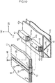
- the floor member 13 is fixed to the edge parts 12a of the fixture rail 12 with the screws 14, thus producing the upper floor 11 made up of the fixture rail 12 and the floor member 13 formed as one body.
- the dimension in the width direction (sleeper direction) of the upper floor 11 is substantially the same as the dimension in the width direction (sleeper direction) of the inside of the railway vehicle structure 1.
- a length that allows easy handling of the upper floor 11 carried into the vehicle for example, approximately 2 [m] is chosen.
- the vibration-proof rubber 10 is fixed with an adhesive at a predetermined position on the top surface of the underframe 2 (surface of the face plate 2a), and then the first horizontal piece 15a of the support member 15 is fixed with an adhesive to the top surface of the vibration-proof rubber 10 while the support member 15 is being positioned so as to satisfy the above positional relations between the vertical piece 20a, the horizontal piece 20b and the protrusion 20c of the protruding part 20, and the vertical piece 15b, the second horizontal piece 15c and the protrusion 15d of the support member 15.
- the upper floor 11 is positioned and placed on the top surface of the first horizontal piece 15a of the support member 15. Moreover, the screw 16 is inserted into the fixture rail 12 from the upward opening part of the fixture rail 12, and this screw 16 is screwed into the support member 15 via the fixture rail 12, thus fixing the fixture rail 12 to the support member 15. As this work is repeated, the upper floors 11 are connected in series to each other along their longitudinal direction, forming a continuous single-body floor with less visible joints. The form or the like of the joint parts of the upper floors 11 in order to connect the upper floors 11 in series to each other along the longitudinal direction (rail direction) of the railway vehicle structure 1 will be described later.
- FIG. 3 shows a configuration example in the case where the above vibration-proof support structure providing vibration-proof support of the upper floor 11 is employed in a railway vehicle in which the top surface of the underframe 2 and the bottom surface of the floor have smaller dimensions.
- This vibration-proof support structure has a structure similar to the vibration-proof support structure according to this embodiment described above with reference to FIG. 2 , except that the thickness of a vibration-proof rubber 21 is smaller and that the height dimension of a vertical piece 22b of a support member 22 is shorter.
- 22a denotes a first horizontal piece of the support member
- 22c denotes a second horizontal piece of the support member
- 22d denotes a protrusion of the support member 22.
- a railway train set made up of a plurality of railway vehicles includes a railway vehicle having a truck equipped with a main motor, a railway vehicle which is not equipped with a main motor, and a railway vehicle equipped with a current collector on its roof in order to supply electric power from overhead lines to the railway vehicle, or the like.
- a height dimension H1 ( FIG. 2 ) from the top surface of the underframe 2 (surface of the face plate 2a) to the bottom surface of the upper floor 11 and thus increasing the height dimension from the top surface of the upper floor 11 to the bottom surface of the ceiling 8 may be taken.
- a height dimension H2 ( FIG. 3 ) from the top surface of the underframe 2 to the bottom surface of the upper floor 11 can be reduced simply by reducing the height dimension of the vertical piece 22b of the support member 22 and the height dimension of the vibration-proof rubber 21, as shown in FIG. 3 .
- the railway vehicle in which the dimension from the top surface of the underframe 2 to the bottom surface of the upper floor 11 is smaller can be dealt with by employing the support member 22 in which the height dimension of the vertical piece 22b is smaller and by using the vibration-proof rubber 21 with a smaller thickness. Therefore, there is no need to change the dimension of the vertical piece 20a (horizontal piece 20b, protrusion 20c) or the like extruded integrally with the underframe 2, according to the height dimension from the top surface of the underframe 2 to the bottom surface of the upper floor 11. Thus, there is no increase in the types of the underframe 2 or no preparation of a plurality of dies (molds used for extrusion) for the extruded members forming the underframe 2, and increase in the manufacturing cost can be restrained.
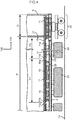
- FIG. 4 is a cross-sectional view in a direction along the longitudinal direction of the railway vehicle having the above vibration-proof support structure according to the embodiment (cross-sectional view taken along C-C in FIG. 2 ) .
- the railway vehicle has vestibule sections D at the ends in the longitudinal direction (rail direction) and has a passenger cabin section P in the middle in its longitudinal direction.
- the vestibule section D is a space situated above a truck 30 and has doorways in the side structures 3 ( FIG. 1 ) which passengers use for boarding and alighting.
- the vestibule section D and the passenger cabin section P are partitioned by a partition board 31, and the partition board 31 is provided with a door (not shown) communicating from the vestibule section D to the passenger cabin section P.
- the truck 30 and underfloor equipment 32, 33 are provided under the floor of the railway vehicle.
- the underfloor equipment 32 is a power pack having an internal combustion engine and a power generator.
- the underfloor equipment 33 is a control device which controls a brake provided on the truck 30.
- the underfloor equipment 32 has a movable part and therefore is highly likely to apply vibration to the underframe 2.
- the underfloor equipment 33 has no movable part and therefore less likely to apply vibration to the underframe 2. If the truck 30 is equipped with a main motor, vibration due to the rotation of the main motor is transmitted to the underframe 2. Even if the truck 30 is not equipped with a main motor, vibration tends to be transmitted from the truck 30 to the underframe 2 because of joints of tracks 34 and misalignment of the tracks 34 or the like.
- the upper floor 11 provided at a position P1 above the underfloor equipment 32 applying vibration to the underframe 2 is fixed to the top surface of the underframe 2 via the vibration-proof rubber 10 (vibration-proof support).
- the upper floor 11 provided at a position P2 above the underfloor equipment 33 not applying vibration to the underframe 2 is directly fixed to the horizontal piece 20b of the protruding part 20 provided on the underframe 2 without using the vibration-proof rubber 10 arranged on the top surface of the underframe 2 (no vibration-proof support, see FIG. 9 ).
- the upper floors 11 are connected in series along the longitudinal direction (rail direction) of the railway vehicle structure 1 and arranged on the underframe 2.
- a male contact part 11b is provided at one end in the longitudinal direction (rail direction) of the upper floor 11, and a female contact part 11a is provided at the other end in the longitudinal direction of the upper floor 11.
- the vibration-proof rubber 10 is continuously arranged along the longitudinal direction (rail direction) of the underframe 2, whereas the protruding part 20 of the underframe 2 and the support member 15 are dispersedly arranged along the longitudinal direction of the underframe 2.
- This is a measure for achieving a lighter weight of the railway vehicle structure 1.
- redundant parts of protruding bodies having the same cross-sectional shape as the protruding part 20
- extruded integrally with the underframe 2 and continuously along the longitudinal direction (rail direction) of the underframe 2 are cut off with grinder or the like, thus forming the individual protruding parts 20.
- the protruding parts 20 need not be provided dispersedly and those protruding bodies may be directly used as the protruding parts 20.
- the horizontal piece 20b of the protruding part 20 provided on the underframe 2 locks the second horizontal piece 15c of the support member 15 fixed to the upper floor 11 from moving in the direction away from the top surface of the underframe 2 and therefore the upper floor 11 can be restrained from floating up from the underframe 2.
- the impact acting on the railway vehicle is not necessarily limited only to the direction along the direction of travel.
- cases where an automobile collides with the lateral side of the railway vehicle at a railway crossing or the like are conceivable.
- the configuration of the vertical piece 20a and the like of the protruding part 20 provided on the underframe 2 and the configuration of the vertical piece 15b and the like of the support member 15 are arranged with plane symmetry about the vertical cross section in the center part of the railway vehicle structure 1, even if the upper floor 11 receives repetitive forces in the direction intersecting with the direction of travel, the vertical piece 20a of the protruding part 20 of the underframe 2 locks the movement in the width direction (sleeper direction) of the vertical piece 15b of the support member 15, and even if the upper floor 11 is about to be lifted upward by a force in the horizontal direction, the horizontal piece 20b of the protruding part 20 of the underframe 2 locks the upward movement of the second horizontal piece 15c of the support member 15.
- the protrusion 20c is provided on the protruding part 20 of the underframe 2 and similarly the protrusion 15d is provided on the support member 15 so that the protrusion 20c and the protrusion 15d engage with each other when the upper floor 11 is about to be lifted upward, the separation of the upper floor 11 from the underframe 2 can be effectively restrained. Therefore, even if an impact in a horizontal plane (impact in the width direction or in a slant direction) acts on the railway vehicle, the separation of the upper floor 11 from the underframe 2 can be effectively restrained.
- these protrusion 20c and protrusion 15d contribute to enhance the strengths and rigidities of the horizontal piece 20b of the corresponding protruding part 20 and the second horizontal piece 15c of the support member 15 and can effectively prevent these horizontal pieces 20b, 15c from being damaged even if an impact acts on the upper floor 11.
- the second horizontal piece 15c of the support member 15 is inserted between the horizontal piece 20b of the protruding part 20 provided on the underframe 2 and the top face plate 2a of the underframe 2, and the support member 15 is fixed on top of the vibration-proof rubber 10 with a configuration in which the horizontal piece 20b of the protruding part 20 and the second horizontal piece 15c of the support member 15 spatially overlap with each other in the direction perpendicular to the top surface of the underframe 2 (arrow 130 in FIG. 2 ), as described above.
- the gap (space) is provided between the horizontal piece 20b of the protruding part 20 and the second horizontal piece 15c of the support member 15, between the horizontal end part of the horizontal piece 20b of the protruding part 20 and the vertical piece 15b of the support member 15, between the horizontal end part of the second horizontal piece 15c of the support member 15 and the vertical piece 20a of the protruding part 20, between the protrusion 20c of the protruding part 20 and the protrusion 15d of the support member 15, between the protrusion 20c of the protruding part 20 and the second horizontal piece 15c of the support member 15, and between the protrusion 15d of the support member 15 and the horizontal piece 20b of the protruding part 20.
- the protruding part 20 of the underframe 2 is provided with plane symmetry about the vertical cross section in the center part of the railway vehicle structure 1, the types of component members of the underframe 2 extruded integrally with the protruding part 20 can be reduced. That is, for example, the extruded member (double-skin member) in the right-hand-side half in the width direction (sleeper direction) of the underframe 2 is extruded from the front toward the back, and the extruded member (double-skin member) in the left-hand-side half is extruded from the back toward the front, and these are placed opposite each other in the width direction and joined together to form the underframe 2. With this configuration (structure with plane symmetry about the vertical cross section in the center part), the number of types of component members of the underframe 2 can be reduced and therefore design cost and manufacturing cost can be reduced.
- the vertical piece 20a of the protruding part 20 of the underframe 2 is provided near the connecting part between the face plate 2a forming the top surface of the underframe 2 and the slant rib 2c connecting both face plates 2a, 2b, the strength and rigidity of the protruding part 20 can be enhanced. That is, when an impact occurs on the railway vehicle and the upper floor 11 is about to move upward, the second horizontal piece 15c of the support member 15 fixed to the upper floor 11 is locked by the horizontal piece 20b of the protruding part 20 provided on the underframe 2.
- a vertical rib 2d connecting the face plate 2a and the face plate 2b below the vertical piece 20a of the protruding part 20 may be provided so as to secure the strength and rigidity of the vertical piece 20a, as shown in FIG. 5 .
- the upper floor 11 presents vibration in a local deformation mode which is partial, and the upper floor 11 shows behavior as an object with a plurality of degrees of freedom, having with a plurality of masses and a spring, instead of a single mass.
- the legs 6a of the seats 6 and the legs 7a of the tables 7 are fixed directly above the vibration-proof rubber 10, when the weight of the seats 6 and the weight of passengers seated there act on the vibration-proof rubber 10 via the fixture rail 12, the natural vibration frequency of a spring mass system using the vibration-proof rubber 10 as a spring and the upper floor 11 as a mass is smaller than in the case where the seats 6 are fixed to the upper floor 11 in areas other than directly above the vibration-proof rubber 10. Therefore, the frequency range where a vibration-proof effect can be expected is enlarged toward lower frequencies and therefore a high vibration-proof effect can be achieved. This has the effect of further reducing in-vehicle noises.
- the highly rigid fixture rail 12 tends to be a node of vibration and the upper floor 11 is supported by the vibration-proof rubber 10 at the position of the node, a structure in which the vibration of the underframe 2 is less likely to be propagated to the upper floor 11 is provided.
- the legs 6a of the seats 6 are fixed by the highly rigid fixture rail 12, durability against an upward impact load which acts to tear off the legs 6a of the seats 6 from the upper floor 11 at the time of impact is improved, compared with the case where the fixture rail 12 is not provided.
- the support member 15 can be bonded and fixed to the top surface of the vibration-proof rubber 10 in advance and the upper floor 11 can be fixed there, the positioning of the support member 15 is easy and the ease of assembly is improved.
- FIG. 6 shows the vibration-proof support structure of the upper floor 11 according to the second embodiment.
- a protruding part 41 with an inverted L-shaped cross section is integrally extruded with the underframe 40, along the longitudinal direction (rail direction) of the underframe 40.
- the protruding part 41 includes a vertical piece 41a extending in a vertical direction from the face plate 40a, a horizontal piece 41b extending in a horizontal direction of a top end part of the vertical piece 41a, and a protrusion 41c protruding downward from a horizontal end part of the horizontal piece 41b (protruding toward a second horizontal piece 43c of a support member 43, described later), and is formed continuously or dispersedly along the longitudinal direction of the underframe 40.
- the horizontal piece 41b of the protruding part 41 is formed with a broader width in the width direction (sleeper direction) than the horizontal piece 20b of the protruding part 20 in the first embodiment ( FIG. 2 ).
- the vertical piece 41a is provided near the connecting part between the face plate 40a forming the top surface of the underframe 40 and a slant rib 40c connecting the face plate 40a and a face plate 40b.
- a vibration-proof rubber 42 having substantially the same width as the horizontal piece 41b of the protruding part 41 and having the same length as the support member 43, described below, in the longitudinal direction (rail direction), is fixed with an adhesive, and the support member 43 is fixed to the top part of the vibration-proof rubber 42.
- This support member 43 has a substantially C-shaped cross section and includes a first horizontal piece 43a, a vertical piece 43b extending downward from one end part in the width direction of the first horizontal piece 43a, a second horizontal piece 43c extending in a horizontal direction from a bottom end part of the vertical piece 43b so as to face the first horizontal piece 43a, and a protrusion 43d protruding upward from a horizontal end part of the second horizontal piece 43c (protruding toward the horizontal piece 41b of the protruding part 41).
- the support member 43 has the second horizontal piece 43c inserted between the horizontal piece 41b of the protruding part 41 and the top face plate 40a of the underframe 40, and the surface facing the second horizontal piece 43c, of the first horizontal piece 43a, is fixed with an adhesive to the top surface of the vibration-proof rubber 42 in such a way that the horizontal piece 41b of the protruding part 41 and the second horizontal piece 43c of the support member 43 spatially overlap in a direction perpendicular to the top surface of the underframe 40 (arrow 130).
- a gap is provided between the horizontal piece 41b of the protruding part 41 and the second horizontal piece 43c of the support member 43, between a horizontal end part of the horizontal piece 41b of the protruding part 41 and the vertical piece 43b of the support member 43, between the protrusion 41c of the protruding part 41 and the second horizontal piece 43c of the support member 43, between a horizontal end part of the second horizontal piece 43c of the support member 43 and the vertical piece 41a of the protruding part 41, and between the protrusion 43d of the support member 43 and the horizontal piece 41b of the protruding part 41.
- the configuration of the protruding part 41 (vertical piece 41a, horizontal piece 41b, protrusion 41c) of the underframe 40 and the configuration of the support member 43 (first horizontal piece 43a, vertical piece 43b, second horizontal piece 43c, protrusion 43d) are arranged with plane symmetry about a vertical cross section in the center part of the railway vehicle structure 1 (cross section taken along B-B in FIG. 1 ).
- a gap g2 is also provided between the vertical piece 43b of the support member 43 and a side surface 42a of the vibration-proof rubber 42, thus forming a configuration which does not prevent deformation of the vibration-proof rubber 10 elastically supporting the upper floor 11 when a load acts thereon. Moreover, since the gap g2 is provided to the side surface 42a of the vibration-proof rubber 42, a configuration in which a rubber with a small spring constant and a high vibration insulation effect (soft rubber with a low rubber hardness) can be selected as the vibration-proof rubber 42 is formed.
- a cut-out 43e is provided at an open end part in the width direction of the first horizontal piece 43a of the support member 43, thus achieving lighter weight of the support member 43.
- the upper floor 11 made up of the fixture rail 12 and the floor member 13 formed as one body is produced by the technique described above in the first embodiment.
- the vibration-proof rubber 42 is fixed with an adhesive onto the horizontal piece 41b of each protruding part 41 of the underframe 40, and then the surface facing the second horizontal piece 43c, of the first horizontal piece 43a of the support member 43, is fixed with an adhesive to the top surface of the vibration-proof rubber 42 while the support member 43 is being positioned so as to satisfy the above positional relations between the vertical piece 41a, the horizontal piece 41b and the protrusion 41c of the protruding part 41 of the underframe 40, and the first horizontal piece 43a, the vertical piece 43b, the second horizontal piece 43c and the protrusion 43d of the support member 43.
- the upper floor 11 is positioned and placed on the top surface of the first horizontal piece 43a of the support member 43. Moreover, the screw 16 is inserted into the fixture rail 12 from the upward opening part of the fixture rail 12, and this screw 16 is screwed into the support member 43 via the fixture rail 12, thus fixing the fixture rail 12 to the support member 43. As this work is repeated, the upper floors 11 are connected in series to each other along their longitudinal direction, forming a continuous single-body floor with less visible joints.
- the second horizontal piece 43c of the support member 43 strikes the horizontal piece 41b of the protruding part 41, and the upward movement of the upper floor 11 is thus restrained.
- the gap is present between the horizontal piece 41b of the protruding part 41 and the second horizontal piece 43c of the support member 43, and a vibration-proof rubber similar to the vibration-proof rubber 42 may be provided in this gap as well.
- the vibration-proof support structure according to this embodiment described above with reference FIG. 6 and a rigid support structure as shown in FIG. 7 may be used together.
- This rigid support structure is formed by a protruding part 44 with a F-shaped cross section extruded integrally with the underframe 40 along the longitudinal direction of the underframe 40, on the top surface side of the underframe 40 (the side of the face plate 40a on the inner side of the vehicle) .
- the protruding part 44 includes a vertical piece 44a extending in a vertical direction from the face plate 40a, a first horizontal piece 44b extending in a horizontal direction from a top end part of the vertical piece 44a, a second horizontal piece 44c extending in a horizontal direction from a middle stage position of the vertical piece 44a so as to face the first horizontal piece 44b, and a protrusion 44d protruding downward from the end of the second horizontal piece 44c.
- the vertical piece 44a is provided near the connecting part between the face plate 40a of the underframe 40 and the slant rib 40c connected aslant to the face plate 40a.
- the height from the face plate 40a to the top surface of the first horizontal piece 44b is formed to be the same as the height to the top surface of the first horizontal piece 43a of the support member 43 in the vibration-proof support structure described above with reference to FIG. 6
- the height from the face plate 40a to the second horizontal piece 44c is formed to be the same as the height to the top surface of the horizontal piece 41b of the protruding part 41 in the vibration-proof support structure described above with reference to FIG. 6 .
- the upper floor 11 is positioned and placed on the top surface of the first horizontal piece 44b of the protruding part 44 and is fixed to the protruding part 44 (and hence the underframe 40) by having the screw 16 inserted into the fixture rail 12 from the site opening upward of the fixture rail 12 and then screwing this screw 16 into the first horizontal piece 44b of the protruding part 44 via the fixture rail 12.
- the vibration-proof support structure described above with reference to FIG. 6 is provided at the position P1 above the underfloor equipment 32 made up of the power pack having the internal combustion engine and the power generator, and the rigid support structure described above with reference to FIG. 7 is provided at the position P2 above the underfloor equipment 33 made up of the control device, the rigid support structure and the vibration-proof support structure can be used together.
- the protruding part 41 ( FIG. 6 ) of the vibration-proof support structure can be prepared by eliminating the part above the second horizontal piece 44c of the protruding part 44, there is no need to change the shape of the underframe 40 for different sites, and a common shape of the underframe 40 can be used regardless of whether the support mechanism of the upper floor 11 is the rigid support structure or the vibration-proof support structure.
- the height of the upper floor 11 can be lowered by eliminating the part above the second horizontal piece 44c of the above protruding part 44 so as to form the protruding part 41 of FIG. 6 and then directly fixing the fixture rail 12 to the horizontal piece 41b of this protruding part 41 with the screw 16, as shown in FIG. 9 .
- configurations with different floor heights for different railway vehicles can be easily achieved and a broad range of vehicles types can be dealt with.
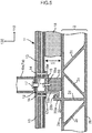
- the protruding part 41 may be provided continuously along the longitudinal direction (rail direction) of the underframe 40, then an anchor hole 41ba may be provided in the horizontal piece 41b of the protruding part 41, and an anchor pin 46 may be inserted in the anchor hole 41ba, as shown in FIG. 10 .
- the anchor pin 46 and the anchor hole 41ba do not contact each other, but the anchor pin 46 is fixed in a hole 12b provided in the fixture rail 12.
- the anchor pin 46 and the anchor hole 41ba do not contact each other, whereas when the upper floor 11 is about to move in the longitudinal direction (rail direction) at the time of collision, the anchor pin 46 strikes the anchor hole 41ba, restraining the movement of the upper floor 11.
- the anchor pin 46 may also be used as the bolt 17 ( FIG. 6 ) fixing the legs 6a of the seats 6.
- the above embodiments are examples and the configurations of the invention are not limited to these.
- the cases where the horizontal pieces 15a, 22a, 43a of the support members 15, 22, 43 are bonded to the top surfaces of the vibration-proof rubbers 10, 21, 42 are described.
- the horizontal pieces 15a, 22a, 43a of the support members 15, 22, 43 may be fixed to the bottom surface of the upper floor 11, and the positional relations between the protruding parts 20, 41 of the underframe 2, 40 and the support members 15, 22, 43 may be formed as described above.
- the seats 6 may be directly fixed to the upper floor 11 without providing the fixture rail 12.
- the vibration-proof rubbers 10, 21, 42, 45 are used as elastic members which elastically support the upper floor 11 are described.
- the invention is not limited to these, and elastic members other than rubber, such as a spring or hard sponge, for example, can be broadly used as such elastic members.
- the protruding parts 15d, 20c, 22d, 41c, 43d, 44d are extruded integrally with the underframes 2, 40 are described.
- the protruding parts 15d, 20c, 22d, 41c, 43d, 44d may be formed separately from the underframes 2, 40 and the protruding parts 15d, 20c, 22d, 41c, 43d, 44d may be fixed to the underframes 2, 40 by screwing or welding, or the like.
- extruding the protruding parts 15d, 20c, 22d, 41c, 43d, 44d integrally with the underframes 2, 40 can increase the strength of the protruding parts 15d, 20c, 22d, 41c, 43d, 44d in the direction of tension (upward direction).
- the protruding parts 20, 41, 44 and the support members 15, 22, 43 are configured as described above with reference to FIG. 2 , FIG. 3 or FIG. 6 are described.
- the invention is not limited to these.
- various configurations other than the configurations described above with reference to FIG. 2 , FIG. 3 or FIG. 6 can be broadly applied as the configurations of these support members and protruding parts.
- the invention is not limited to this. Also in the underframe 40 according to the second embodiment, a vertical rib connecting the face plate 40a and the face plate 40b below the vertical piece 41a of the protruding part 41 may be similarly provided according to need.
- the invention is not limited to this and such a structure for restraining the movement in the longitudinal direction of the upper floor 11 may also be applied to the vibration-proof support structure according to the first embodiment.
- the invention can be broadly applied to railway vehicles having various configurations in which an upper floor forming the floor is laid down on the top surface side of an underframe.
Description
- The preset invention relates to a railway vehicle and particularly relates to a railway vehicle having a floor structure that restrain separation of an upper floor from an underframe when the railway vehicle collides or the like.
- A background art in this technical field is PTL 1, for example. This publication describes that "a plurality of floor supports is fixed on a top surface of an underframe made up of a hollow extruded material having a closed cross section, and a floor board is supported via an elastic member provided with the floor supports."
- Also,
PTL 2 describes that "a locking step part is formed on both side surfaces of a vibration-proof member which supports an interior floor board, and a housing groove opening on the top side is formed in a floor bearing member provided on a structure floor board. On the inner surface of one sidewall of the housing groove, a protruding part which engages with the top surface of the locking step part on one side surface of the vibration-proof member is provided and a support part extending outward in the horizontal direction, continuing from the top part of the other sidewall of the housing groove, is provided. A holding plate having a protruding part which engages with the top surface of the locking step part on the other side surface of the vibration-proof member is attached to the support part." - Also,
PTL 3 describes that "the mounting has a first C-shaped profiled part (1), with inward facing projections (5), and a second profiled part (2) with upper and low, both parts of plastic or aluminum. Elastic bearing supporting it on the first profile when not under load, or under small load only. The elastic bearing part is glued to the second profile, and another bearing part (12) is glued to the first profile." -
- PTL 1:
JP-A-9-150738 - PTL 2:
JP-A-2001-48017 - PTL 3: Specification of European Patent Application Publication No.
1,193,165 -
EP A 1508489 proposes a floor support having side extensions.DD A 253229 DE A 102013200628 proposes a mounting element for a railway vehicle roof. - According to the related-art techniques, since the direction of a load acting on the vibration-proof rubber due to the weight of the seats fixed to the top surface of the upper floor, and the upper floor, is basically downward in the vertical direction, it is assumed that only a load in the direction of compression acts on the vibration-proof. However, if the railway vehicle collides with an obstacle at a railway crossing or another railway vehicle, a force in the direction of travel of the railway vehicle is applied to the centers of gravity of the seats fixed to the upper floor. At the same time, a moment formed by the above force acting on the centers of gravity of the seats, the height dimension from the centers of gravity to the upper floor, and the arm dimension, acts on the seat. Then, this moment causes an impact load which acts to tear off the upper floor from the underframe of the railway vehicle.
- Conventionally, if the impact load as described above, which is not considered for the vibration-proof rubber, acts, the bonding surface between the top surface of the vibration-proof rubber and the upper floor, the vibration-proof rubber itself, or the bonding surface between the bottom surface of the vibration-proof rubber and a vibration-proof bearing provided on the underframe breaks, posing the risk of the upper floor being torn off upward and floating up.
- Therefore, it is desired that, in a railway vehicle with its upper floor supported in a vibration-proof manner, an elastic support structure for the upper floor which stops the upper floor with seats, tables and the like fixed thereto from floating up, without obstructing elastic support of the upper floor by an ordinary elastic member such as a vibration-proof rubber when a large impact acts on the railway vehicle, should be achieved.
- In view of the foregoing circumstances, the invention is to propose a railway vehicle whose upper floor can be effectively prevented from floating upward when a large impact acts on the railway vehicle, without obstructing elastic support of the upper floor.
- To solve the foregoing problems, according to the invention, a railway vehicle according to claim 1 is provided.
- According to this railway vehicle, even if a load in the direction of lifting (tearing off) the upper floor acts on the upper floor as an impact of collision or the like occurs, the protruding part locks the movement of the support member and therefore the upward and downward movement of the upper floor is restrained as well. In this case, the protruding part and the support member do not affect the elastic support of the upper floor by the elastic member.
- According to the invention, a railway vehicle whose upper floor can be effectively prevented from floating upward when a large impact acts on the railway vehicle, without obstructing elastic support of the upper floor, can be achieved.
-
- [
FIG. 1] FIG. 1 is a vertical cross-sectional view in the longitudinal direction of a railway vehicle. - [
FIG. 2] FIG. 2 is a cross-sectional view showing a vibration-proof support structure according to a first embodiment. - [
FIG. 3] FIG. 3 is a cross-sectional view showing another configuration example of the vibration-proof support structure according to the first embodiment. - [
FIG. 4] FIG. 4 is a cross-sectional view showing the cross-sectional configuration in a direction along the longitudinal direction of a railway vehicle having the vibration-proof support structure according to the first embodiment. - [
FIG. 5] FIG. 5 is a cross-sectional view showing another configuration example of the vibration-proof support structure according to the first embodiment. - [
FIG. 6] FIG. 6 is a cross-sectional view showing a vibration-proof support structure according to a second embodiment. - [
FIG. 7] FIG. 7 is a cross-sectional view showing a configuration example of an upper floor support structure according to the second embodiment. - [
FIG. 8] FIG. 8 is a cross-sectional view showing a configuration example of the vibration-proof support structure according to the second embodiment. - [
FIG. 9] FIG. 9 is a cross-sectional view showing a configuration example of the upper floor support structure according to the second embodiment. - [
FIG. 10] FIG. 10 is a perspective view showing an application example of the vibration-proof support structure according to the second embodiment. - Hereinafter, an embodiment of the invention will be described with reference to the drawings.
-
FIG. 1 is a vertical cross-sectional view in the longitudinal direction of a railway vehicle according to the first embodiment.FIG. 2 is a detailed view in which the part A inFIG. 1 is enlarged. - Typically, a railway vehicle structure 1 is made up of an
underframe 2 forming a floor,side structures 3 provided upright at the ends in the width direction of theunderframe 2,end structures 4 provided upright at the ends in the longitudinal direction of the underframe 2 (seeFIG. 4 ), and aroof structure 5 placed on top of theside structures 3 and theend structures 4. - Particularly, each of the
underframe 2, theside structures 3 and theroof structure 5 is made up of a member formed by coupling two face plates facing each other into one body with ribs. These members are manufactured by extruding an aluminum alloy and are called double-skin members. These double-skin members used for the railway vehicle structure 1 are often extruded along the longitudinal direction of the railway vehicle. - On the top surface of the
underframe 2 inside the railway vehicle structure 1, anupper floor 11 is laid down via a vibration-proof rubber 10 (FIG. 2 ), andseats 6 and tables 7 or the like are fixed to theupper floor 11. - As shown in
FIG. 2 , theupper floor 11 is made up of afixture rail 12 used when fixing theseats 6 and the tables 7 or the like to theupper floor 11, and afloor member 13 connected to thefixture rail 12 and thus forming the floor. Thefixture rail 12 is a channel member with a C-cross section opening upward. Thefloor member 13 is fastened withscrews 14 toedge parts 12a protruding in the width direction (sleeper direction) indicated by anarrow 120, from side bottom end parts of thefixture rail 12. Thefloor member 13 is formed of, for example, a wood member or aluminum honeycomb member as a core member, with thin face plates of an aluminum alloy or the like bonded to both sides of the core member. Thefixture rail 12 is produced by extrusion of an aluminum alloy, similarly to theunderframe 2. - The
upper floor 11 is carried into the railway vehicle structure 1 and positioned at a predetermined position, and subsequently placed on asupport member 15 fixed to the top surface of the vibration-proof rubber 10 fixed in advance at a predetermined position on the top surface of theunderframe 2. Then, both end parts in the width direction (sleeper direction) of theupper floor 11 are screwed to support parts, not shown, provided on bottom end parts of theside structures 3, and thefixture rail 12 situated at a center part in the width direction of theupper floor 11 is fastened to thesupport member 15 on the vibration-proof rubber 10 withscrews 16. - Subsequently, bottom end parts of
legs 6a of theseats 6 andlegs 7a of the tables 7 are fixed withbolts 17 to a top part of thefixture rail 12 forming theupper floor 11. In the space between theunderframe 2 and theupper floor 11, a predetermined plate-like member 18 such as a sound absorbing member or heat insulation member is arranged according to need. Also, as a support structure in which the bottom end parts of theside structures 3 support both end parts in the width direction of theupper floor 11, a vibration-proof support structure according to this embodiment made up of a protrudingpart 20 on theunderframe 2, described later, thesupport member 15 and the vibration-proof rubber 10 may be employed. - Next, the attachment structure of the
upper floor 11 to theunderframe 2 is described. In the case of this embodiment, on the side of the top surface of the underframe 2 (the surface of aface plate 2a on the inside of the vehicle, offace plates part 20 with an inverted L-shaped cross section is integrally extruded with theunderframe 2, along the longitudinal direction (rail direction) of theunderframe 2 indicated by anarrow 110 inFIG. 4 (seeFIG. 4 ). The protrudingpart 20 includes avertical piece 20a extending in a vertical direction from theface plate 2a, ahorizontal piece 20b extending in a horizontal direction of a top end part of thevertical piece 20a, and aprotrusion 20c protruding downward from a horizontal end part of thehorizontal piece 20b (protruding toward a secondhorizontal piece 15c of thesupport member 15, described later). Thevertical piece 20a is provided near the connecting part between theface plate 2a of theunderframe 2 and aslant rib 2c. - On the top surface of the
face plate 2a which is degreased, the vibration-proof rubber 10 is fixed with an adhesive along the longitudinal direction (rail direction) of theface plate 2a and subsequently thesupport member 15 is fixed to the top part of the vibration-proof rubber 10 with an adhesive. Thissupport member 15 includes a firsthorizontal piece 15a, avertical piece 15b extending downward from one end part in the width direction of the firsthorizontal piece 15a, a secondhorizontal piece 15c extending in a horizontal direction from a bottom end part of thevertical piece 15b, and aprotrusion 15d protruding upward from a horizontal end part of the secondhorizontal piece 15c (protruding toward thehorizontal piece 20b of the protruding part 20). - The
support member 15 has the secondhorizontal piece 15c inserted between thehorizontal piece 20b of the protrudingpart 20 of theunderframe 2 and thetop face plate 2a of theunderframe 2 and is bonded onto the vibration-proof rubber 10 in such a way that the secondhorizontal piece 15c and thehorizontal piece 20b of the protrudingpart 20 spatially overlap in a direction perpendicular to the top surface of the underframe 2 (arrow 130). - In this case, a gap (space) is provided between the
horizontal piece 20b of the protrudingpart 20 and the secondhorizontal piece 15c of thesupport member 15, between a horizontal end part of thehorizontal piece 20b of the protrudingpart 20 and thevertical piece 15b of thesupport member 15, between a horizontal end part of the secondhorizontal piece 15c of thesupport member 15 and thevertical piece 20a of the protrudingpart 20, between theprotrusion 20c of the protrudingpart 20 and theprotrusion 15d of thesupport member 15, between theprotrusion 20c of the protrudingpart 20 and the secondhorizontal piece 15c of thesupport member 15, and between theprotrusion 15d of thesupport member 15 and thehorizontal piece 20b of the protrudingpart 20. Thus, a configuration which can elastically support theupper floor 11 without obstructing the deformation of the vibration-proof rubber 10 at the time of normal use of the railway vehicle is provided. When the railway vehicle is operated, even if a vertical load acts on the vibration-proof rubber 10 and causes compressive deformation or a horizontal load is applied to cause shear deformation, these gaps (spaces) are secured and therefore theupper floor 11 is elastically supported by the vibration-proof rubber 10. - The configuration of the protruding part 20 (
vertical piece 20a,horizontal piece 20b,protrusion 20c) of theunderframe 2 and the configuration of the support member 15 (firsthorizontal piece 15a,vertical piece 15b, secondhorizontal piece 15c, protrusion 17d) are arranged with plane symmetry about a vertical cross section in the center part of the railway vehicle structure 1 (cross section taken along B-B inFIG. 1 ). - A gap g1 (see
FIG. 2 ) is provided between thevertical piece 15b of thesupport member 15 and aside surface 10a of the vibration-proof rubber 10, thus forming a configuration which does not prevent deformation of the vibration-proof rubber 10 elastically supporting theupper floor 11 when a load is applied thereto. Moreover, since the gap g1 is provided to theside surface 10a of the vibration-proof rubber 10, a configuration which can use a rubber with a small spring constant and a high vibration insulation effect (soft rubber with a low rubber hardness) as the vibration-proof rubber 10 is formed. A cut-out 15e is provided at an open end part in the width direction of the firsthorizontal piece 15a of thesupport member 15, thus achieving lighter weight of thesupport member 15. - Next, an example of a method for fixing the
upper floor 11 to the top surface of theunderframe 2 will be described. First, thefloor member 13 is fixed to theedge parts 12a of thefixture rail 12 with thescrews 14, thus producing theupper floor 11 made up of thefixture rail 12 and thefloor member 13 formed as one body. The dimension in the width direction (sleeper direction) of theupper floor 11 is substantially the same as the dimension in the width direction (sleeper direction) of the inside of the railway vehicle structure 1. As the dimension in the longitudinal direction (rail direction) of theupper floor 11, a length that allows easy handling of theupper floor 11 carried into the vehicle (for example, approximately 2 [m]) is chosen. - Subsequently, the vibration-
proof rubber 10 is fixed with an adhesive at a predetermined position on the top surface of the underframe 2 (surface of theface plate 2a), and then the firsthorizontal piece 15a of thesupport member 15 is fixed with an adhesive to the top surface of the vibration-proof rubber 10 while thesupport member 15 is being positioned so as to satisfy the above positional relations between thevertical piece 20a, thehorizontal piece 20b and theprotrusion 20c of the protrudingpart 20, and thevertical piece 15b, the secondhorizontal piece 15c and theprotrusion 15d of thesupport member 15. - After this, the
upper floor 11 is positioned and placed on the top surface of the firsthorizontal piece 15a of thesupport member 15. Moreover, thescrew 16 is inserted into thefixture rail 12 from the upward opening part of thefixture rail 12, and thisscrew 16 is screwed into thesupport member 15 via thefixture rail 12, thus fixing thefixture rail 12 to thesupport member 15. As this work is repeated, theupper floors 11 are connected in series to each other along their longitudinal direction, forming a continuous single-body floor with less visible joints. The form or the like of the joint parts of theupper floors 11 in order to connect theupper floors 11 in series to each other along the longitudinal direction (rail direction) of the railway vehicle structure 1 will be described later. -
FIG. 3 , in which the parts corresponding to those inFIG. 2 are denoted by the same reference signs, shows a configuration example in the case where the above vibration-proof support structure providing vibration-proof support of theupper floor 11 is employed in a railway vehicle in which the top surface of theunderframe 2 and the bottom surface of the floor have smaller dimensions. This vibration-proof support structure has a structure similar to the vibration-proof support structure according to this embodiment described above with reference toFIG. 2 , except that the thickness of a vibration-proof rubber 21 is smaller and that the height dimension of a vertical piece 22b of asupport member 22 is shorter. InFIG. 3 , 22a denotes a first horizontal piece of thesupport member support member support member 22. - Here, a railway train set made up of a plurality of railway vehicles includes a railway vehicle having a truck equipped with a main motor, a railway vehicle which is not equipped with a main motor, and a railway vehicle equipped with a current collector on its roof in order to supply electric power from overhead lines to the railway vehicle, or the like.
- In the railway vehicle having the truck equipped with the main motor, the vibration of the main motor installed on the truck and the vibration generated in a traction device which gives the railway vehicle structure 1 a tractive force and a braking force of the truck, or the like, tend to be transmitted to the
underframe 2. Therefore, in the railway vehicle having the truck equipped with the main motor, it is desirable that vibration-proof capability should be enhanced by increasing the thickness (height dimension) of the vibration-proof rubber or by reducing its rubber hardness, so that the vibration of theunderframe 2 will not be transmitted to theupper floor 11. Meanwhile, in the railway vehicle having the truck which is not equipped with a main motor, since the vibration levels of the foregoing vibrations transmitted to theunderframe 2 are lower and high vibration-proof capability for theupper floor 11 is not required, there is no need to achieve a large thickness of the vibration-proof rubber. - Also, in the railway vehicle equipped with the current collector, since the height of the
roof structure 5 is lowered, the height of a ceiling 8 (FIG. 1 ) is lowered as well. Therefore, in some cases, measures of reducing a height dimension H1 (FIG. 2 ) from the top surface of the underframe 2 (surface of theface plate 2a) to the bottom surface of theupper floor 11 and thus increasing the height dimension from the top surface of theupper floor 11 to the bottom surface of theceiling 8 may be taken. In such cases, a height dimension H2 (FIG. 3 ) from the top surface of theunderframe 2 to the bottom surface of theupper floor 11 can be reduced simply by reducing the height dimension of the vertical piece 22b of thesupport member 22 and the height dimension of the vibration-proof rubber 21, as shown inFIG. 3 . - The railway vehicle in which the dimension from the top surface of the
underframe 2 to the bottom surface of theupper floor 11 is smaller can be dealt with by employing thesupport member 22 in which the height dimension of the vertical piece 22b is smaller and by using the vibration-proof rubber 21 with a smaller thickness. Therefore, there is no need to change the dimension of thevertical piece 20a (horizontal piece 20b,protrusion 20c) or the like extruded integrally with theunderframe 2, according to the height dimension from the top surface of theunderframe 2 to the bottom surface of theupper floor 11. Thus, there is no increase in the types of theunderframe 2 or no preparation of a plurality of dies (molds used for extrusion) for the extruded members forming theunderframe 2, and increase in the manufacturing cost can be restrained. -
FIG. 4 is a cross-sectional view in a direction along the longitudinal direction of the railway vehicle having the above vibration-proof support structure according to the embodiment (cross-sectional view taken along C-C inFIG. 2 ) . The railway vehicle has vestibule sections D at the ends in the longitudinal direction (rail direction) and has a passenger cabin section P in the middle in its longitudinal direction. Generally, the vestibule section D is a space situated above atruck 30 and has doorways in the side structures 3 (FIG. 1 ) which passengers use for boarding and alighting. The vestibule section D and the passenger cabin section P are partitioned by apartition board 31, and thepartition board 31 is provided with a door (not shown) communicating from the vestibule section D to the passenger cabin section P. - Under the floor of the railway vehicle, the
truck 30 andunderfloor equipment underfloor equipment 32 is a power pack having an internal combustion engine and a power generator. Theunderfloor equipment 33 is a control device which controls a brake provided on thetruck 30. Theunderfloor equipment 32 has a movable part and therefore is highly likely to apply vibration to theunderframe 2. Theunderfloor equipment 33 has no movable part and therefore less likely to apply vibration to theunderframe 2. If thetruck 30 is equipped with a main motor, vibration due to the rotation of the main motor is transmitted to theunderframe 2. Even if thetruck 30 is not equipped with a main motor, vibration tends to be transmitted from thetruck 30 to theunderframe 2 because of joints oftracks 34 and misalignment of thetracks 34 or the like. - The
upper floor 11 provided at a position P1 above theunderfloor equipment 32 applying vibration to theunderframe 2 is fixed to the top surface of theunderframe 2 via the vibration-proof rubber 10 (vibration-proof support). Theupper floor 11 provided at a position P2 above theunderfloor equipment 33 not applying vibration to theunderframe 2 is directly fixed to thehorizontal piece 20b of the protrudingpart 20 provided on theunderframe 2 without using the vibration-proof rubber 10 arranged on the top surface of the underframe 2 (no vibration-proof support, seeFIG. 9 ). - The
upper floors 11 are connected in series along the longitudinal direction (rail direction) of the railway vehicle structure 1 and arranged on theunderframe 2. Amale contact part 11b is provided at one end in the longitudinal direction (rail direction) of theupper floor 11, and afemale contact part 11a is provided at the other end in the longitudinal direction of theupper floor 11. When placing and positioning theupper floor 11 on the top surface of theunderframe 2, theupper floor 11 is laid down while themale contact parts 11b and thefemale contact parts 11a of theupper floors 11 arranged in series are placed opposite each other and meshed with each other. - In the case of this embodiment, as clear from
FIG. 4 , the vibration-proof rubber 10 is continuously arranged along the longitudinal direction (rail direction) of theunderframe 2, whereas the protrudingpart 20 of theunderframe 2 and thesupport member 15 are dispersedly arranged along the longitudinal direction of theunderframe 2. This is a measure for achieving a lighter weight of the railway vehicle structure 1. To this end, redundant parts of protruding bodies (having the same cross-sectional shape as the protruding part 20) extruded integrally with theunderframe 2 and continuously along the longitudinal direction (rail direction) of theunderframe 2 are cut off with grinder or the like, thus forming the individual protrudingparts 20. If the requirement of lighter weight is not strict, the protrudingparts 20 need not be provided dispersedly and those protruding bodies may be directly used as the protrudingparts 20. - In the railway vehicle according to the embodiment having the foregoing configuration, if the railway vehicle collides with an obstacle or the like at a railway crossing or the like, an inertial force in the direction of travel (rail direction) of the railway vehicle acts on the
upper floor 11, theseats 6 and the tables 7 or the like and therefore a force in the direction of travel occurs in these components. However, since thesupport member 15 with theupper floor 11 mechanically fastened with thescrew 16 is bonded to the top surface of the vibration-proof rubber 10, the movement of theupper floor 11 into the direction of travel is restrained by the shear force of the adhesive. - Similarly, since the
legs 6a of theseats 6 and thelegs 7a of the tables 7, on which the force in the direction of travel acts, are fixed to thefixture rail 12 forming theupper floor 11, the movement in the direction of travel, of thelegs 6a and thelegs 7a fastened to theupper floor 11, is restrained, similarly to theupper floor 11. However, the seat surfaces, backrests and the like of theseats 6 will move in the direction of travel of the railway vehicle. Therefore, a moment formed by the inertial force in the direction of travel acting on the centers of gravity of theseats 6 and the tables 7, the height dimension from these centers of gravity to theupper floor 11, and the arm length, acts on the fastening parts between theupper floor 11 and thelegs 6a (legs 7a). - Even if a force to lift the
upper floor 11 upward acts because of this moment, and the above bonding surface is torn off, thehorizontal piece 20b of the protrudingpart 20 provided on theunderframe 2 locks the secondhorizontal piece 15c of thesupport member 15 fixed to theupper floor 11 from moving in the direction away from the top surface of theunderframe 2 and therefore theupper floor 11 can be restrained from floating up from theunderframe 2. - Also, the impact acting on the railway vehicle is not necessarily limited only to the direction along the direction of travel. For example, cases where an automobile collides with the lateral side of the railway vehicle at a railway crossing or the like are conceivable. Even in such cases, since the configuration of the
vertical piece 20a and the like of the protrudingpart 20 provided on theunderframe 2 and the configuration of thevertical piece 15b and the like of thesupport member 15 are arranged with plane symmetry about the vertical cross section in the center part of the railway vehicle structure 1, even if theupper floor 11 receives repetitive forces in the direction intersecting with the direction of travel, thevertical piece 20a of the protrudingpart 20 of theunderframe 2 locks the movement in the width direction (sleeper direction) of thevertical piece 15b of thesupport member 15, and even if theupper floor 11 is about to be lifted upward by a force in the horizontal direction, thehorizontal piece 20b of the protrudingpart 20 of theunderframe 2 locks the upward movement of the secondhorizontal piece 15c of thesupport member 15. - Moreover, since the
protrusion 20c is provided on the protrudingpart 20 of theunderframe 2 and similarly theprotrusion 15d is provided on thesupport member 15 so that theprotrusion 20c and theprotrusion 15d engage with each other when theupper floor 11 is about to be lifted upward, the separation of theupper floor 11 from theunderframe 2 can be effectively restrained. Therefore, even if an impact in a horizontal plane (impact in the width direction or in a slant direction) acts on the railway vehicle, the separation of theupper floor 11 from theunderframe 2 can be effectively restrained. - Also, these
protrusion 20c andprotrusion 15d contribute to enhance the strengths and rigidities of thehorizontal piece 20b of the corresponding protrudingpart 20 and the secondhorizontal piece 15c of thesupport member 15 and can effectively prevent thesehorizontal pieces upper floor 11. - Moreover, in the railway vehicle according to this embodiment, the second
horizontal piece 15c of thesupport member 15 is inserted between thehorizontal piece 20b of the protrudingpart 20 provided on theunderframe 2 and thetop face plate 2a of theunderframe 2, and thesupport member 15 is fixed on top of the vibration-proof rubber 10 with a configuration in which thehorizontal piece 20b of the protrudingpart 20 and the secondhorizontal piece 15c of thesupport member 15 spatially overlap with each other in the direction perpendicular to the top surface of the underframe 2 (arrow 130 inFIG. 2 ), as described above. - In this case, the gap (space) is provided between the
horizontal piece 20b of the protrudingpart 20 and the secondhorizontal piece 15c of thesupport member 15, between the horizontal end part of thehorizontal piece 20b of the protrudingpart 20 and thevertical piece 15b of thesupport member 15, between the horizontal end part of the secondhorizontal piece 15c of thesupport member 15 and thevertical piece 20a of the protrudingpart 20, between theprotrusion 20c of the protrudingpart 20 and theprotrusion 15d of thesupport member 15, between theprotrusion 20c of the protrudingpart 20 and the secondhorizontal piece 15c of thesupport member 15, and between theprotrusion 15d of thesupport member 15 and thehorizontal piece 20b of the protrudingpart 20. With this configuration, the deformation of the vibration-proof rubber 10 due to the vibration of the railway vehicle is not obstructed and therefore a sufficient vibration-proof support (vibration insulation) effect can be achieved. Moreover, since the gaps between thehorizontal piece 20b of the protrudingpart 20 and the secondhorizontal piece 15c of thesupport member 15 and the like are maintained as described above, the occurrence of noises caused by collisions between these members can be restrained as well. - In addition, in the railway vehicle according to this embodiment, since the protruding
part 20 of theunderframe 2 is provided with plane symmetry about the vertical cross section in the center part of the railway vehicle structure 1, the types of component members of theunderframe 2 extruded integrally with the protrudingpart 20 can be reduced. That is, for example, the extruded member (double-skin member) in the right-hand-side half in the width direction (sleeper direction) of theunderframe 2 is extruded from the front toward the back, and the extruded member (double-skin member) in the left-hand-side half is extruded from the back toward the front, and these are placed opposite each other in the width direction and joined together to form theunderframe 2. With this configuration (structure with plane symmetry about the vertical cross section in the center part), the number of types of component members of theunderframe 2 can be reduced and therefore design cost and manufacturing cost can be reduced. - Also, in the railway vehicle according to this embodiment, since the
vertical piece 20a of the protrudingpart 20 of theunderframe 2 is provided near the connecting part between theface plate 2a forming the top surface of theunderframe 2 and theslant rib 2c connecting bothface plates part 20 can be enhanced. That is, when an impact occurs on the railway vehicle and theupper floor 11 is about to move upward, the secondhorizontal piece 15c of thesupport member 15 fixed to theupper floor 11 is locked by thehorizontal piece 20b of the protrudingpart 20 provided on theunderframe 2. At this time, a large force acts on thehorizontal piece 20b, thevertical piece 20a supporting thehorizontal piece 20b, and theface plate 2a to which thevertical piece 20a is connected. However, since the railway vehicle according to this embodiment has the above configuration, even if an impact force acts in the direction in which thevertical piece 20a of the protrudingpart 20 is pulled upward in the process of restraining the upward movement of theupper floor 11, thevertical piece 20a can sufficiently endure the impact. - Meanwhile, depending on the positional relations with the
legs 6a of theseats 6 and thelegs 7a of the tables 7, it may be difficult in some cases to provide the protrudingpart 20 near the connecting part between theface plate 2a and theslant rib 2c of theunderframe 2. In such cases, avertical rib 2d connecting theface plate 2a and theface plate 2b below thevertical piece 20a of the protrudingpart 20 may be provided so as to secure the strength and rigidity of thevertical piece 20a, as shown inFIG. 5 . - Moreover, generally, in the high frequency range of 160 [Hz] and above, where in-vehicle noises pose problems, the
upper floor 11 presents vibration in a local deformation mode which is partial, and theupper floor 11 shows behavior as an object with a plurality of degrees of freedom, having with a plurality of masses and a spring, instead of a single mass. With respect to this point, in the railway vehicle according to this embodiment, since thelegs 6a of theseats 6 and thelegs 7a of the tables 7 are fixed directly above the vibration-proof rubber 10, when the weight of theseats 6 and the weight of passengers seated there act on the vibration-proof rubber 10 via thefixture rail 12, the natural vibration frequency of a spring mass system using the vibration-proof rubber 10 as a spring and theupper floor 11 as a mass is smaller than in the case where theseats 6 are fixed to theupper floor 11 in areas other than directly above the vibration-proof rubber 10. Therefore, the frequency range where a vibration-proof effect can be expected is enlarged toward lower frequencies and therefore a high vibration-proof effect can be achieved. This has the effect of further reducing in-vehicle noises. - Also, since the highly
rigid fixture rail 12 tends to be a node of vibration and theupper floor 11 is supported by the vibration-proof rubber 10 at the position of the node, a structure in which the vibration of theunderframe 2 is less likely to be propagated to theupper floor 11 is provided. Moreover, since thelegs 6a of theseats 6 are fixed by the highlyrigid fixture rail 12, durability against an upward impact load which acts to tear off thelegs 6a of theseats 6 from theupper floor 11 at the time of impact is improved, compared with the case where thefixture rail 12 is not provided. Furthermore, since thesupport member 15 can be bonded and fixed to the top surface of the vibration-proof rubber 10 in advance and theupper floor 11 can be fixed there, the positioning of thesupport member 15 is easy and the ease of assembly is improved. -
FIG. 6 , in which the parts corresponding to those inFIG. 2 are denoted by the same reference signs, shows the vibration-proof support structure of theupper floor 11 according to the second embodiment. In the case of this embodiment, on the side of the top surface of an underframe 40 (the side of aface plate 40a on the inside of the vehicle), a protrudingpart 41 with an inverted L-shaped cross section is integrally extruded with theunderframe 40, along the longitudinal direction (rail direction) of theunderframe 40. - The protruding
part 41 includes avertical piece 41a extending in a vertical direction from theface plate 40a, ahorizontal piece 41b extending in a horizontal direction of a top end part of thevertical piece 41a, and aprotrusion 41c protruding downward from a horizontal end part of thehorizontal piece 41b (protruding toward a secondhorizontal piece 43c of asupport member 43, described later), and is formed continuously or dispersedly along the longitudinal direction of theunderframe 40. Thehorizontal piece 41b of the protrudingpart 41 is formed with a broader width in the width direction (sleeper direction) than thehorizontal piece 20b of the protrudingpart 20 in the first embodiment (FIG. 2 ). Also, thevertical piece 41a is provided near the connecting part between theface plate 40a forming the top surface of theunderframe 40 and aslant rib 40c connecting theface plate 40a and aface plate 40b. - On the top surface of the protruding
part 41 which is degreased, a vibration-proof rubber 42 having substantially the same width as thehorizontal piece 41b of the protrudingpart 41 and having the same length as thesupport member 43, described below, in the longitudinal direction (rail direction), is fixed with an adhesive, and thesupport member 43 is fixed to the top part of the vibration-proof rubber 42. Thissupport member 43 has a substantially C-shaped cross section and includes a firsthorizontal piece 43a, avertical piece 43b extending downward from one end part in the width direction of the firsthorizontal piece 43a, a secondhorizontal piece 43c extending in a horizontal direction from a bottom end part of thevertical piece 43b so as to face the firsthorizontal piece 43a, and aprotrusion 43d protruding upward from a horizontal end part of the secondhorizontal piece 43c (protruding toward thehorizontal piece 41b of the protruding part 41). - The
support member 43 has the secondhorizontal piece 43c inserted between thehorizontal piece 41b of the protrudingpart 41 and thetop face plate 40a of theunderframe 40, and the surface facing the secondhorizontal piece 43c, of the firsthorizontal piece 43a, is fixed with an adhesive to the top surface of the vibration-proof rubber 42 in such a way that thehorizontal piece 41b of the protrudingpart 41 and the secondhorizontal piece 43c of thesupport member 43 spatially overlap in a direction perpendicular to the top surface of the underframe 40 (arrow 130). - In this case, a gap (space) is provided between the
horizontal piece 41b of the protrudingpart 41 and the secondhorizontal piece 43c of thesupport member 43, between a horizontal end part of thehorizontal piece 41b of the protrudingpart 41 and thevertical piece 43b of thesupport member 43, between theprotrusion 41c of the protrudingpart 41 and the secondhorizontal piece 43c of thesupport member 43, between a horizontal end part of the secondhorizontal piece 43c of thesupport member 43 and thevertical piece 41a of the protrudingpart 41, and between theprotrusion 43d of thesupport member 43 and thehorizontal piece 41b of the protrudingpart 41. Thus, a configuration which can elastically support theupper floor 11 without obstructing the deformation of the vibration-proof rubber 42 at the time of normal use of the railway vehicle is provided. When the railway vehicle is operated, even if a vertical load acts on the vibration-proof rubber 42 and causes compressive deformation or a horizontal load is applied to cause shear deformation, these gaps (spaces) are secured and therefore theupper floor 11 is elastically supported by the vibration-proof rubber 42. - The configuration of the protruding part 41 (
vertical piece 41a,horizontal piece 41b,protrusion 41c) of theunderframe 40 and the configuration of the support member 43 (firsthorizontal piece 43a,vertical piece 43b, secondhorizontal piece 43c,protrusion 43d) are arranged with plane symmetry about a vertical cross section in the center part of the railway vehicle structure 1 (cross section taken along B-B inFIG. 1 ). - A gap g2 is also provided between the
vertical piece 43b of thesupport member 43 and aside surface 42a of the vibration-proof rubber 42, thus forming a configuration which does not prevent deformation of the vibration-proof rubber 10 elastically supporting theupper floor 11 when a load acts thereon. Moreover, since the gap g2 is provided to theside surface 42a of the vibration-proof rubber 42, a configuration in which a rubber with a small spring constant and a high vibration insulation effect (soft rubber with a low rubber hardness) can be selected as the vibration-proof rubber 42 is formed. A cut-out 43e is provided at an open end part in the width direction of the firsthorizontal piece 43a of thesupport member 43, thus achieving lighter weight of thesupport member 43. - Next, an example of a method for fixing the
upper floor 11 to the top surface of theunderframe 40 will be described. First, theupper floor 11 made up of thefixture rail 12 and thefloor member 13 formed as one body is produced by the technique described above in the first embodiment. - Subsequently, the vibration-
proof rubber 42 is fixed with an adhesive onto thehorizontal piece 41b of each protrudingpart 41 of theunderframe 40, and then the surface facing the secondhorizontal piece 43c, of the firsthorizontal piece 43a of thesupport member 43, is fixed with an adhesive to the top surface of the vibration-proof rubber 42 while thesupport member 43 is being positioned so as to satisfy the above positional relations between thevertical piece 41a, thehorizontal piece 41b and theprotrusion 41c of the protrudingpart 41 of theunderframe 40, and the firsthorizontal piece 43a, thevertical piece 43b, the secondhorizontal piece 43c and theprotrusion 43d of thesupport member 43. - After this, the
upper floor 11 is positioned and placed on the top surface of the firsthorizontal piece 43a of thesupport member 43. Moreover, thescrew 16 is inserted into thefixture rail 12 from the upward opening part of thefixture rail 12, and thisscrew 16 is screwed into thesupport member 43 via thefixture rail 12, thus fixing thefixture rail 12 to thesupport member 43. As this work is repeated, theupper floors 11 are connected in series to each other along their longitudinal direction, forming a continuous single-body floor with less visible joints. - Also in this embodiment, as described in the first embodiment, against an impact load which causes the above adhesive to be torn off and causes the
upper floor 11 to move upward when the railway vehicle collides, the secondhorizontal piece 43c of thesupport member 43 strikes thehorizontal piece 41b of the protrudingpart 41, and the upward movement of theupper floor 11 is thus restrained. Thus, the effect of achieving both the effect similar to the first embodiment, that is, the vibration-proof capability of theupper floor 11, and safety at the time of collision, can be achieved. Also, in this embodiment, the gap is present between thehorizontal piece 41b of the protrudingpart 41 and the secondhorizontal piece 43c of thesupport member 43, and a vibration-proof rubber similar to the vibration-proof rubber 42 may be provided in this gap as well. - Also, for sections where the need for the vibration proof property is low, such as the floors of general sections that are not above the truck, inside the railway vehicle structure 1, the vibration-proof support structure according to this embodiment described above with reference
FIG. 6 and a rigid support structure as shown inFIG. 7 may be used together. This rigid support structure is formed by a protrudingpart 44 with a F-shaped cross section extruded integrally with theunderframe 40 along the longitudinal direction of theunderframe 40, on the top surface side of the underframe 40 (the side of theface plate 40a on the inner side of the vehicle) . - The protruding
part 44 includes avertical piece 44a extending in a vertical direction from theface plate 40a, a firsthorizontal piece 44b extending in a horizontal direction from a top end part of thevertical piece 44a, a secondhorizontal piece 44c extending in a horizontal direction from a middle stage position of thevertical piece 44a so as to face the firsthorizontal piece 44b, and aprotrusion 44d protruding downward from the end of the secondhorizontal piece 44c. Thevertical piece 44a is provided near the connecting part between theface plate 40a of theunderframe 40 and theslant rib 40c connected aslant to theface plate 40a. - Also, in the protruding
part 44, the height from theface plate 40a to the top surface of the firsthorizontal piece 44b is formed to be the same as the height to the top surface of the firsthorizontal piece 43a of thesupport member 43 in the vibration-proof support structure described above with reference toFIG. 6 , and the height from theface plate 40a to the secondhorizontal piece 44c is formed to be the same as the height to the top surface of thehorizontal piece 41b of the protrudingpart 41 in the vibration-proof support structure described above with reference toFIG. 6 . - Then, the
upper floor 11 is positioned and placed on the top surface of the firsthorizontal piece 44b of the protrudingpart 44 and is fixed to the protruding part 44 (and hence the underframe 40) by having thescrew 16 inserted into thefixture rail 12 from the site opening upward of thefixture rail 12 and then screwing thisscrew 16 into the firsthorizontal piece 44b of the protrudingpart 44 via thefixture rail 12. - Therefore, for example, in
FIG. 4 , if the vibration-proof support structure described above with reference toFIG. 6 is provided at the position P1 above theunderfloor equipment 32 made up of the power pack having the internal combustion engine and the power generator, and the rigid support structure described above with reference toFIG. 7 is provided at the position P2 above theunderfloor equipment 33 made up of the control device, the rigid support structure and the vibration-proof support structure can be used together. - In this case, in providing the vibration-proof support structure, since the protruding part 41 (
FIG. 6 ) of the vibration-proof support structure can be prepared by eliminating the part above the secondhorizontal piece 44c of the protrudingpart 44, there is no need to change the shape of theunderframe 40 for different sites, and a common shape of theunderframe 40 can be used regardless of whether the support mechanism of theupper floor 11 is the rigid support structure or the vibration-proof support structure. - Meanwhile, at sites where the thickness of the vibration-
proof rubber 42 should be greater than in the vibration-proof support structure according to this embodiment described above with reference toFIG. 6 so as to enhance vibration-proof capability, it is possible to eliminate the entirety of the protruding part 44 (FIG. 7 ), screw thefixture rail 12 on top of a vibration-proof rubber 45 fixed to theunderframe 40 by a method such as bonding, and thus fix theupper floor 11 to theunderframe 40, as shown inFIG. 8 . In this case, this part itself does not have the function of restraining the upward displacement of theupper floor 11 when the vehicle collides. However, since theupper floors 11 are fastened to each other in the longitudinal direction (rail direction) of the railway vehicle as described above with reference toFIG. 4 , if upward displacement is restrained in theupper floors 11 in front of and behind oneupper floor 11, thisupper floor 11 will not be displaced upward alone. - Also, for example, in the railway vehicle equipped with the current collector on the roof, if the floor needs to be lowered as the height of the roof structure 5 (
FIG. 1 ) is lowered, and if there is no need for vibration-proof support of the floor, the height of theupper floor 11 can be lowered by eliminating the part above the secondhorizontal piece 44c of the above protrudingpart 44 so as to form the protrudingpart 41 ofFIG. 6 and then directly fixing thefixture rail 12 to thehorizontal piece 41b of this protrudingpart 41 with thescrew 16, as shown inFIG. 9 . In this way, according to the invention, in response to different demands for vibration-proof capability and floor height, configurations with different floor heights for different railway vehicles can be easily achieved and a broad range of vehicles types can be dealt with. - In the railway vehicle, if the movement in the longitudinal direction (rail direction) of the
upper floor 11 needs to be partially restrained rigidly, the protrudingpart 41 may be provided continuously along the longitudinal direction (rail direction) of theunderframe 40, then an anchor hole 41ba may be provided in thehorizontal piece 41b of the protrudingpart 41, and ananchor pin 46 may be inserted in the anchor hole 41ba, as shown inFIG. 10 . In this case, theanchor pin 46 and the anchor hole 41ba do not contact each other, but theanchor pin 46 is fixed in ahole 12b provided in thefixture rail 12. Thus, in normal time, theanchor pin 46 and the anchor hole 41ba do not contact each other, whereas when theupper floor 11 is about to move in the longitudinal direction (rail direction) at the time of collision, theanchor pin 46 strikes the anchor hole 41ba, restraining the movement of theupper floor 11. Theanchor pin 46 may also be used as the bolt 17 (FIG. 6 ) fixing thelegs 6a of theseats 6. - The above embodiments are examples and the configurations of the invention are not limited to these. For example, in the above first and second embodiments, the cases where the
horizontal pieces support members proof rubbers horizontal pieces support members upper floor 11, and the positional relations between the protrudingparts underframe support members support members proof rubbers seats 6 may be directly fixed to theupper floor 11 without providing thefixture rail 12. Even in the case where thesupport members proof rubbers legs 6a of theseats 6 are not fixed above the vibration-proof rubbers upper floor 11 similar to those in the above first and second embodiments can be achieved. - Also, in the above first and second embodiments, the cases where the vibration-
proof rubbers upper floor 11 are described. However, the invention is not limited to these, and elastic members other than rubber, such as a spring or hard sponge, for example, can be broadly used as such elastic members. - Moreover, in the above first and second embodiments, the cases where the protruding
parts underframes parts underframes parts underframes parts underframes parts - Furthermore, in the above first and second embodiments, the protruding
parts support members FIG. 2 ,FIG. 3 orFIG. 6 are described. However, the invention is not limited to these. In short, as long as the movement in the direction away from the top surfaces of theunderframes upper floor 11 can be locked by the protruding parts, various configurations other than the configurations described above with reference toFIG. 2 ,FIG. 3 orFIG. 6 can be broadly applied as the configurations of these support members and protruding parts. - Also, while the case where the
vertical rib 2d connecting theface plate 2a and theface plate 2b below thevertical piece 20a of the protrudingpart 20 is provided on theunderframe 2 is described in the above first embodiment, the invention is not limited to this. Also in theunderframe 40 according to the second embodiment, a vertical rib connecting theface plate 40a and theface plate 40b below thevertical piece 41a of the protrudingpart 41 may be similarly provided according to need. - Moreover, while the case where the structure for restraining the movement in the longitudinal direction of the
upper floor 11 described above with reference toFIG. 10 is applied only to the vibration-proof support structure according to the second embodiment is described in the above second embodiment, the invention is not limited to this and such a structure for restraining the movement in the longitudinal direction of theupper floor 11 may also be applied to the vibration-proof support structure according to the first embodiment. - The invention can be broadly applied to railway vehicles having various configurations in which an upper floor forming the floor is laid down on the top surface side of an underframe.
- 1 ... railway vehicle structure, 2, 40 ... underframe, 2a, 2b, 40a, 40b ... face plate, 2c, 40c ... slant rib, 2d ... vertical rib, 6 ... seat, 6a, 7a ... leg, 7 ... table, 10, 21, 42, 45 ... vibration-proof rubber, 11 ... upper floor, 12 ... fixture rail, 12a ... edge part, 12b ... hole, 13 ... floor member, 14, 16 ... screw, 15, 22, 43 ... support member, 15a, 15c, 20b, 22c, 41b, 44b, 44d ... horizontal piece, 15b, 20a, 22b, 41a, 43b, 44a ... vertical piece, 15d, 20c, 22d, 41c, 43d, 44d ... protrusion, 15e ... cut-out, 17, 46 ... bolt, 20, 41, 44 ... protruding part, 30 ... truck, 33 ... underfloor equipment, 110 ... longitudinal direction (rail direction), 120 ... width direction (sleeper direction), 130 ... height direction.
Claims (6)
- A railway vehicle in which an upper floor (11) forming a floor is laid down on a top surface side of an underframe (2, 40), the railway vehicle comprising:a protruding part (20, 41) provided along a longitudinal direction of the underframe, on the top surface of the underframe;an elastic member (10, 21, 42) arranged along the longitudinal direction of the underframe and having a bottom surface fixed to the top surface of the underframe or a top surface of a horizontal piece of the protruding part; anda support member (15, 22, 43) fixed to a top surface of the elastic member and fixed to a bottom surface of the upper floor;wherein the protruding part and the support member are formed in such a way that the protruding part limits movement of the support member in a direction away from the top surface of the underframe;wherein the protruding part includes:a vertical piece (20a, 41a) extending in a vertical direction from the top surface of the underframe; anda protruding portion having the horizontal piece (20b, 41b) extending in a horizontal direction from a top end part of the vertical piece,wherein the support member includes:a first horizontal piece (15a, 22a, 43a) fixed to the bottom surface side of upper floor;a vertical piece (15b, 22b, 43b) extending in the direction of the top surface of the underframe from the first horizontal piece; anda second horizontal piece (15c, 22c, 43c) extending in a horizontal direction from a bottom end part of the vertical piece, andwherein the support memberhas the second horizontal piece inserted between the top surface of the underframe and the horizontal piece of the protruding part and is arranged in such a way that the horizontal piece of the protruding part and the second horizontal piece of the support member spatially overlap with each other in a direction perpendicular to the top surface of the underframe;characterized in that the first horizontal piece is fixed to the top surface of the elastic member, and in that the vertical piece of the support member extends in the direction of the top surface of the underframe from one end part in a width direction of the first horizontal piece.
- The railway vehicle according to claim 1, wherein
a protrusion (20c, 41c) protruding toward the second horizontal piece of the support member is provided at a horizontal end part of the horizontal piece of the protruding part, and
a protrusion (15d, 22d, 43d) protruding toward the horizontal piece of the protruding part is provided at a horizontal end part of the second horizontal piece of the support member. - The railway vehicle according to claim 1, wherein
a configuration of the protruding part and a configuration of the support member are arranged with plane symmetry about a vertical cross section of a center part in the width direction of the underframe. - The railway vehicle according to claim 1, wherein
a gap is provided between the horizontal piece of the protruding part and the second horizontal piece of the support member, between a horizontal end part of the horizontal piece of the protruding part and the vertical piece of the support member, and between a horizontal end part of the second horizontal piece of the support member and the vertical piece of the protruding part. - The railway vehicle according to claim 1, wherein t
he underframe
is formed by extrusion and has a structure in which two face plates (2a, 2b; 40a, 40b) facing each other are connected together with a rib (2c, 2d; 40c), and
the protruding part
is provided near a connecting part between the face plate forming the top surface of the underframe and the rib. - The railway vehicle according to claim 1, comprising
a seat (6) arranged on the upper floor,
wherein a leg (6a) of the seat is fixed at a position directly above the elastic member, on the upper floor.
Priority Applications (1)
| Application Number | Priority Date | Filing Date | Title |
|---|---|---|---|
| EP18180975.7A EP3421318B1 (en) | 2013-09-12 | 2013-09-12 | Railway vehicle |
Applications Claiming Priority (1)
| Application Number | Priority Date | Filing Date | Title |
|---|---|---|---|
| PCT/JP2013/074702 WO2015037100A1 (en) | 2013-09-12 | 2013-09-12 | Railway vehicle |
Related Child Applications (2)
| Application Number | Title | Priority Date | Filing Date |
|---|---|---|---|
| EP18180975.7A Division EP3421318B1 (en) | 2013-09-12 | 2013-09-12 | Railway vehicle |
| EP18180975.7A Division-Into EP3421318B1 (en) | 2013-09-12 | 2013-09-12 | Railway vehicle |
Publications (3)
| Publication Number | Publication Date |
|---|---|
| EP3045371A1 EP3045371A1 (en) | 2016-07-20 |
| EP3045371A4 EP3045371A4 (en) | 2017-04-26 |
| EP3045371B1 true EP3045371B1 (en) | 2018-08-15 |
Family
ID=52665242
Family Applications (2)
| Application Number | Title | Priority Date | Filing Date |
|---|---|---|---|
| EP18180975.7A Active EP3421318B1 (en) | 2013-09-12 | 2013-09-12 | Railway vehicle |
| EP13893466.6A Active EP3045371B1 (en) | 2013-09-12 | 2013-09-12 | Railway vehicle |
Family Applications Before (1)
| Application Number | Title | Priority Date | Filing Date |
|---|---|---|---|
| EP18180975.7A Active EP3421318B1 (en) | 2013-09-12 | 2013-09-12 | Railway vehicle |
Country Status (3)
| Country | Link |
|---|---|
| EP (2) | EP3421318B1 (en) |
| JP (1) | JP6082470B2 (en) |
| WO (1) | WO2015037100A1 (en) |
Families Citing this family (6)
| Publication number | Priority date | Publication date | Assignee | Title |
|---|---|---|---|---|
| GB2551582B (en) * | 2016-06-24 | 2019-11-13 | Bombardier Transp Gmbh | Vehicle body of a public transportation vehicle provided with floating floor panels |
| CN106240587B (en) * | 2016-08-30 | 2018-12-14 | 中车株洲电力机车有限公司 | A kind of rail vehicle vehicle head structure |
| CN107719012A (en) * | 2017-10-31 | 2018-02-23 | 中车资阳机车有限公司 | A kind of overhead rail vehicle running gear |
| JP7061974B2 (en) * | 2019-01-24 | 2022-05-02 | 近畿車輌株式会社 | Railroad vehicle floor structure and its manufacturing method |
| JP2022106016A (en) * | 2021-01-06 | 2022-07-19 | 株式会社日立製作所 | Rail vehicle and manufacturing method of the same |
| JP2022107168A (en) * | 2021-01-08 | 2022-07-21 | 株式会社日立製作所 | Rail vehicle and manufacturing method of the same |
Family Cites Families (11)
| Publication number | Priority date | Publication date | Assignee | Title |
|---|---|---|---|---|
| DD253229A1 (en) * | 1986-10-13 | 1988-01-13 | Goerlitz Waggonbau Veb | INSULATED SUPPRESSOR FLOOR FOR RAIL VEHICLES |
| JPH09150738A (en) | 1995-11-30 | 1997-06-10 | Nippon Sharyo Seizo Kaisha Ltd | Floor structure of railway rolling stock |
| JP3955699B2 (en) * | 1999-08-11 | 2007-08-08 | 東海旅客鉄道株式会社 | Mounting structure of anti-vibration member for supporting interior floor boards of railway vehicles |
| AT409751B (en) | 2000-10-02 | 2002-11-25 | Getzner Werkstoffe Gmbh | MOUNTING PART FOR THE ELASTIC FASTENING OF VEHICLE FLOOR PANELS |
| DE10337930A1 (en) * | 2003-08-18 | 2005-03-17 | Siemens Ag | Floor of a large-scale vehicle for passenger transport, in particular a rail vehicle |
| JP4275022B2 (en) * | 2003-12-24 | 2009-06-10 | 株式会社神戸製鋼所 | Aluminum extrusions for vehicle floor structures |
| DE102004055011A1 (en) * | 2004-11-15 | 2006-05-18 | Siemens Ag | Component for attaching components to the load-bearing floor structure of a wagon body, in particular a rail vehicle |
| JP5202852B2 (en) * | 2006-06-16 | 2013-06-05 | 東海旅客鉄道株式会社 | Anti-vibration floating floor structure |
| WO2011020245A1 (en) * | 2009-08-21 | 2011-02-24 | 上海磁浮交通发展有限公司 | Floating floor structure of rail vehicle |
| EP2570322B1 (en) * | 2011-09-14 | 2014-12-17 | Bombardier Transportation GmbH | Holder element for constructing a floor of a rail vehicle car, floor of a rail vehicle car and rail vehicle car |
| DE102013200628A1 (en) * | 2013-01-17 | 2014-07-17 | Siemens Aktiengesellschaft | Attachment of a rail vehicle component on a car body roof of a rail vehicle car body |
-
2013
- 2013-09-12 WO PCT/JP2013/074702 patent/WO2015037100A1/en active Application Filing
- 2013-09-12 EP EP18180975.7A patent/EP3421318B1/en active Active
- 2013-09-12 JP JP2015536366A patent/JP6082470B2/en active Active
- 2013-09-12 EP EP13893466.6A patent/EP3045371B1/en active Active
Non-Patent Citations (1)
| Title |
|---|
| None * |
Also Published As
| Publication number | Publication date |
|---|---|
| WO2015037100A1 (en) | 2015-03-19 |
| EP3045371A1 (en) | 2016-07-20 |
| EP3421318B1 (en) | 2019-07-24 |
| EP3045371A4 (en) | 2017-04-26 |
| EP3421318A1 (en) | 2019-01-02 |
| JP6082470B2 (en) | 2017-02-15 |
| JPWO2015037100A1 (en) | 2017-03-02 |
Similar Documents
| Publication | Publication Date | Title |
|---|---|---|
| EP3045371B1 (en) | Railway vehicle | |
| JP4744508B2 (en) | Configurations that allow adaptable payloads | |
| EP1353832B1 (en) | A rail vehicle carbody of modular construction | |
| JP5802160B2 (en) | Railway vehicle equipped with cab and cab | |
| CN105438436B (en) | Aircraft and seat track assembly for vibration isolation of floor mounted components | |
| RU2416550C2 (en) | Aircraft cabin seat guide attachment to floor and aircraft equipped with such attachment | |
| JPWO2017037852A1 (en) | Railway vehicle | |
| JP6359170B2 (en) | Railway vehicle | |
| EP2641804A1 (en) | Composite self-supporting housing for a railway car | |
| JP5730415B2 (en) | Railway vehicle | |
| JP6196536B2 (en) | Railcar interior product mounting structure and interior product mounting method | |
| EP2763880B1 (en) | Rail vehicle having a sound-insulated and vibration-insulated room-within-a-room cab | |
| JP6082709B2 (en) | Floor support structure for moving objects | |
| GB2567736B (en) | Railroad vehicle body structure having shock absorbing structure | |
| JP2008001165A (en) | Vibrationproof floor structure of railroad vehicle | |
| EP4137382A1 (en) | Rail vehicle and method of producing same | |
| CN113022609A (en) | Chassis for magnetic levitation vehicle and magnetic levitation vehicle | |
| GB2505587A (en) | Railroad vehicle with collision energy absorption structure | |
| JP6646429B2 (en) | Mobile structure | |
| JP6726446B2 (en) | Railway car | |
| JPH0123885Y2 (en) | ||
| WO2022074752A1 (en) | Railway vehicle | |
| EP4101637B1 (en) | Furniture supporting assembly, associated supporting installation and vehicle | |
| JP6772338B2 (en) | Floor structure of railway vehicles | |
| JP6629171B2 (en) | Floor structure of moving object |
Legal Events
| Date | Code | Title | Description |
|---|---|---|---|
| PUAI | Public reference made under article 153(3) epc to a published international application that has entered the european phase |
Free format text: ORIGINAL CODE: 0009012 |
|
| 17P | Request for examination filed |
Effective date: 20151222 |
|
| AK | Designated contracting states |
Kind code of ref document: A1 Designated state(s): AL AT BE BG CH CY CZ DE DK EE ES FI FR GB GR HR HU IE IS IT LI LT LU LV MC MK MT NL NO PL PT RO RS SE SI SK SM TR |
|
| AX | Request for extension of the european patent |
Extension state: BA ME |
|
| DAX | Request for extension of the european patent (deleted) | ||
| A4 | Supplementary search report drawn up and despatched |
Effective date: 20170327 |
|
| RIC1 | Information provided on ipc code assigned before grant |
Ipc: B61D 17/10 20060101AFI20170321BHEP |
|
| GRAP | Despatch of communication of intention to grant a patent |
Free format text: ORIGINAL CODE: EPIDOSNIGR1 |
|
| INTG | Intention to grant announced |
Effective date: 20180305 |
|
| GRAS | Grant fee paid |
Free format text: ORIGINAL CODE: EPIDOSNIGR3 |
|
| GRAA | (expected) grant |
Free format text: ORIGINAL CODE: 0009210 |
|
| AK | Designated contracting states |
Kind code of ref document: B1 Designated state(s): AL AT BE BG CH CY CZ DE DK EE ES FI FR GB GR HR HU IE IS IT LI LT LU LV MC MK MT NL NO PL PT RO RS SE SI SK SM TR |
|
| REG | Reference to a national code |
Ref country code: CH Ref legal event code: EP Ref country code: GB Ref legal event code: FG4D Ref country code: AT Ref legal event code: REF Ref document number: 1029393 Country of ref document: AT Kind code of ref document: T Effective date: 20180815 |
|
| REG | Reference to a national code |
Ref country code: IE Ref legal event code: FG4D |
|
| REG | Reference to a national code |
Ref country code: DE Ref legal event code: R096 Ref document number: 602013042216 Country of ref document: DE |
|
| REG | Reference to a national code |
Ref country code: FR Ref legal event code: PLFP Year of fee payment: 6 |
|
| REG | Reference to a national code |
Ref country code: NL Ref legal event code: MP Effective date: 20180815 |
|
| REG | Reference to a national code |
Ref country code: LT Ref legal event code: MG4D |
|
| REG | Reference to a national code |
Ref country code: AT Ref legal event code: MK05 Ref document number: 1029393 Country of ref document: AT Kind code of ref document: T Effective date: 20180815 |
|
| PG25 | Lapsed in a contracting state [announced via postgrant information from national office to epo] |
Ref country code: RS Free format text: LAPSE BECAUSE OF FAILURE TO SUBMIT A TRANSLATION OF THE DESCRIPTION OR TO PAY THE FEE WITHIN THE PRESCRIBED TIME-LIMIT Effective date: 20180815 Ref country code: IS Free format text: LAPSE BECAUSE OF FAILURE TO SUBMIT A TRANSLATION OF THE DESCRIPTION OR TO PAY THE FEE WITHIN THE PRESCRIBED TIME-LIMIT Effective date: 20181215 Ref country code: NL Free format text: LAPSE BECAUSE OF FAILURE TO SUBMIT A TRANSLATION OF THE DESCRIPTION OR TO PAY THE FEE WITHIN THE PRESCRIBED TIME-LIMIT Effective date: 20180815 Ref country code: AT Free format text: LAPSE BECAUSE OF FAILURE TO SUBMIT A TRANSLATION OF THE DESCRIPTION OR TO PAY THE FEE WITHIN THE PRESCRIBED TIME-LIMIT Effective date: 20180815 Ref country code: BG Free format text: LAPSE BECAUSE OF FAILURE TO SUBMIT A TRANSLATION OF THE DESCRIPTION OR TO PAY THE FEE WITHIN THE PRESCRIBED TIME-LIMIT Effective date: 20181115 Ref country code: SE Free format text: LAPSE BECAUSE OF FAILURE TO SUBMIT A TRANSLATION OF THE DESCRIPTION OR TO PAY THE FEE WITHIN THE PRESCRIBED TIME-LIMIT Effective date: 20180815 Ref country code: FI Free format text: LAPSE BECAUSE OF FAILURE TO SUBMIT A TRANSLATION OF THE DESCRIPTION OR TO PAY THE FEE WITHIN THE PRESCRIBED TIME-LIMIT Effective date: 20180815 Ref country code: NO Free format text: LAPSE BECAUSE OF FAILURE TO SUBMIT A TRANSLATION OF THE DESCRIPTION OR TO PAY THE FEE WITHIN THE PRESCRIBED TIME-LIMIT Effective date: 20181115 Ref country code: GR Free format text: LAPSE BECAUSE OF FAILURE TO SUBMIT A TRANSLATION OF THE DESCRIPTION OR TO PAY THE FEE WITHIN THE PRESCRIBED TIME-LIMIT Effective date: 20181116 Ref country code: LT Free format text: LAPSE BECAUSE OF FAILURE TO SUBMIT A TRANSLATION OF THE DESCRIPTION OR TO PAY THE FEE WITHIN THE PRESCRIBED TIME-LIMIT Effective date: 20180815 |
|
| PG25 | Lapsed in a contracting state [announced via postgrant information from national office to epo] |
Ref country code: LV Free format text: LAPSE BECAUSE OF FAILURE TO SUBMIT A TRANSLATION OF THE DESCRIPTION OR TO PAY THE FEE WITHIN THE PRESCRIBED TIME-LIMIT Effective date: 20180815 Ref country code: HR Free format text: LAPSE BECAUSE OF FAILURE TO SUBMIT A TRANSLATION OF THE DESCRIPTION OR TO PAY THE FEE WITHIN THE PRESCRIBED TIME-LIMIT Effective date: 20180815 Ref country code: AL Free format text: LAPSE BECAUSE OF FAILURE TO SUBMIT A TRANSLATION OF THE DESCRIPTION OR TO PAY THE FEE WITHIN THE PRESCRIBED TIME-LIMIT Effective date: 20180815 |
|
| PG25 | Lapsed in a contracting state [announced via postgrant information from national office to epo] |
Ref country code: CZ Free format text: LAPSE BECAUSE OF FAILURE TO SUBMIT A TRANSLATION OF THE DESCRIPTION OR TO PAY THE FEE WITHIN THE PRESCRIBED TIME-LIMIT Effective date: 20180815 Ref country code: RO Free format text: LAPSE BECAUSE OF FAILURE TO SUBMIT A TRANSLATION OF THE DESCRIPTION OR TO PAY THE FEE WITHIN THE PRESCRIBED TIME-LIMIT Effective date: 20180815 Ref country code: PL Free format text: LAPSE BECAUSE OF FAILURE TO SUBMIT A TRANSLATION OF THE DESCRIPTION OR TO PAY THE FEE WITHIN THE PRESCRIBED TIME-LIMIT Effective date: 20180815 Ref country code: ES Free format text: LAPSE BECAUSE OF FAILURE TO SUBMIT A TRANSLATION OF THE DESCRIPTION OR TO PAY THE FEE WITHIN THE PRESCRIBED TIME-LIMIT Effective date: 20180815 Ref country code: EE Free format text: LAPSE BECAUSE OF FAILURE TO SUBMIT A TRANSLATION OF THE DESCRIPTION OR TO PAY THE FEE WITHIN THE PRESCRIBED TIME-LIMIT Effective date: 20180815 |
|
| REG | Reference to a national code |
Ref country code: CH Ref legal event code: PL |
|
| REG | Reference to a national code |
Ref country code: DE Ref legal event code: R097 Ref document number: 602013042216 Country of ref document: DE |
|
| PG25 | Lapsed in a contracting state [announced via postgrant information from national office to epo] |
Ref country code: DK Free format text: LAPSE BECAUSE OF FAILURE TO SUBMIT A TRANSLATION OF THE DESCRIPTION OR TO PAY THE FEE WITHIN THE PRESCRIBED TIME-LIMIT Effective date: 20180815 Ref country code: SM Free format text: LAPSE BECAUSE OF FAILURE TO SUBMIT A TRANSLATION OF THE DESCRIPTION OR TO PAY THE FEE WITHIN THE PRESCRIBED TIME-LIMIT Effective date: 20180815 Ref country code: SK Free format text: LAPSE BECAUSE OF FAILURE TO SUBMIT A TRANSLATION OF THE DESCRIPTION OR TO PAY THE FEE WITHIN THE PRESCRIBED TIME-LIMIT Effective date: 20180815 |
|
| REG | Reference to a national code |
Ref country code: BE Ref legal event code: MM Effective date: 20180930 |
|
| PLBE | No opposition filed within time limit |
Free format text: ORIGINAL CODE: 0009261 |
|
| STAA | Information on the status of an ep patent application or granted ep patent |
Free format text: STATUS: NO OPPOSITION FILED WITHIN TIME LIMIT |
|
| REG | Reference to a national code |
Ref country code: IE Ref legal event code: MM4A |
|
| PG25 | Lapsed in a contracting state [announced via postgrant information from national office to epo] |
Ref country code: MC Free format text: LAPSE BECAUSE OF FAILURE TO SUBMIT A TRANSLATION OF THE DESCRIPTION OR TO PAY THE FEE WITHIN THE PRESCRIBED TIME-LIMIT Effective date: 20180815 Ref country code: LU Free format text: LAPSE BECAUSE OF NON-PAYMENT OF DUE FEES Effective date: 20180912 |
|
| 26N | No opposition filed |
Effective date: 20190516 |
|
| PG25 | Lapsed in a contracting state [announced via postgrant information from national office to epo] |
Ref country code: IE Free format text: LAPSE BECAUSE OF NON-PAYMENT OF DUE FEES Effective date: 20180912 |
|
| PG25 | Lapsed in a contracting state [announced via postgrant information from national office to epo] |
Ref country code: SI Free format text: LAPSE BECAUSE OF FAILURE TO SUBMIT A TRANSLATION OF THE DESCRIPTION OR TO PAY THE FEE WITHIN THE PRESCRIBED TIME-LIMIT Effective date: 20180815 Ref country code: BE Free format text: LAPSE BECAUSE OF NON-PAYMENT OF DUE FEES Effective date: 20180930 Ref country code: CH Free format text: LAPSE BECAUSE OF NON-PAYMENT OF DUE FEES Effective date: 20180930 Ref country code: LI Free format text: LAPSE BECAUSE OF NON-PAYMENT OF DUE FEES Effective date: 20180930 |
|
| PG25 | Lapsed in a contracting state [announced via postgrant information from national office to epo] |
Ref country code: MT Free format text: LAPSE BECAUSE OF NON-PAYMENT OF DUE FEES Effective date: 20180912 |
|
| PG25 | Lapsed in a contracting state [announced via postgrant information from national office to epo] |
Ref country code: TR Free format text: LAPSE BECAUSE OF FAILURE TO SUBMIT A TRANSLATION OF THE DESCRIPTION OR TO PAY THE FEE WITHIN THE PRESCRIBED TIME-LIMIT Effective date: 20180815 |
|
| PG25 | Lapsed in a contracting state [announced via postgrant information from national office to epo] |
Ref country code: PT Free format text: LAPSE BECAUSE OF FAILURE TO SUBMIT A TRANSLATION OF THE DESCRIPTION OR TO PAY THE FEE WITHIN THE PRESCRIBED TIME-LIMIT Effective date: 20180815 |
|
| PG25 | Lapsed in a contracting state [announced via postgrant information from national office to epo] |
Ref country code: CY Free format text: LAPSE BECAUSE OF FAILURE TO SUBMIT A TRANSLATION OF THE DESCRIPTION OR TO PAY THE FEE WITHIN THE PRESCRIBED TIME-LIMIT Effective date: 20180815 Ref country code: MK Free format text: LAPSE BECAUSE OF NON-PAYMENT OF DUE FEES Effective date: 20180815 Ref country code: HU Free format text: LAPSE BECAUSE OF FAILURE TO SUBMIT A TRANSLATION OF THE DESCRIPTION OR TO PAY THE FEE WITHIN THE PRESCRIBED TIME-LIMIT; INVALID AB INITIO Effective date: 20130912 |
|
| PGFP | Annual fee paid to national office [announced via postgrant information from national office to epo] |
Ref country code: IT Payment date: 20230810 Year of fee payment: 11 Ref country code: GB Payment date: 20230727 Year of fee payment: 11 |
|
| PGFP | Annual fee paid to national office [announced via postgrant information from national office to epo] |
Ref country code: FR Payment date: 20230808 Year of fee payment: 11 Ref country code: DE Payment date: 20230802 Year of fee payment: 11 |