EP3045302A1 - Pressing machine - Google Patents
Pressing machine Download PDFInfo
- Publication number
- EP3045302A1 EP3045302A1 EP15002851.2A EP15002851A EP3045302A1 EP 3045302 A1 EP3045302 A1 EP 3045302A1 EP 15002851 A EP15002851 A EP 15002851A EP 3045302 A1 EP3045302 A1 EP 3045302A1
- Authority
- EP
- European Patent Office
- Prior art keywords
- crankshafts
- eccentric shaft
- shaft portions
- pressing machine
- main shaft
- Prior art date
- Legal status (The legal status is an assumption and is not a legal conclusion. Google has not performed a legal analysis and makes no representation as to the accuracy of the status listed.)
- Granted
Links
- 230000033001 locomotion Effects 0.000 claims description 23
- 230000009471 action Effects 0.000 claims description 7
- 238000006073 displacement reaction Methods 0.000 claims description 3
- 230000009467 reduction Effects 0.000 abstract description 5
- 230000005540 biological transmission Effects 0.000 description 47
- 230000007246 mechanism Effects 0.000 description 13
- 230000004044 response Effects 0.000 description 6
- 230000008901 benefit Effects 0.000 description 4
- 238000006243 chemical reaction Methods 0.000 description 3
- 230000000977 initiatory effect Effects 0.000 description 2
- 238000004519 manufacturing process Methods 0.000 description 2
- 230000004048 modification Effects 0.000 description 2
- 238000012986 modification Methods 0.000 description 2
- 230000015572 biosynthetic process Effects 0.000 description 1
- 230000006866 deterioration Effects 0.000 description 1
- 230000000694 effects Effects 0.000 description 1
- 238000005192 partition Methods 0.000 description 1
- 230000001360 synchronised effect Effects 0.000 description 1
Images


Classifications
-
- B—PERFORMING OPERATIONS; TRANSPORTING
- B30—PRESSES
- B30B—PRESSES IN GENERAL
- B30B1/00—Presses, using a press ram, characterised by the features of the drive therefor, pressure being transmitted directly, or through simple thrust or tension members only, to the press ram or platen
- B30B1/26—Presses, using a press ram, characterised by the features of the drive therefor, pressure being transmitted directly, or through simple thrust or tension members only, to the press ram or platen by cams, eccentrics, or cranks
- B30B1/266—Drive systems for the cam, eccentric or crank axis
-
- B—PERFORMING OPERATIONS; TRANSPORTING
- B30—PRESSES
- B30B—PRESSES IN GENERAL
- B30B1/00—Presses, using a press ram, characterised by the features of the drive therefor, pressure being transmitted directly, or through simple thrust or tension members only, to the press ram or platen
- B30B1/26—Presses, using a press ram, characterised by the features of the drive therefor, pressure being transmitted directly, or through simple thrust or tension members only, to the press ram or platen by cams, eccentrics, or cranks
Landscapes
- Engineering & Computer Science (AREA)
- Mechanical Engineering (AREA)
- Press Drives And Press Lines (AREA)
Abstract
Description
- The present invention generally relates to a pressing machine, and more particularly to a pressing machine having an improved structure configured to smoothly transmit a rotary driving force among a plurality of crankshafts that move a slider or slide member to which a pressing die is attached.
- As a pressing machine driven by crankshafts, there is known a pressing machine configured to cause a reciprocatory movement of the slider, to which the pressing die is attached, by synchronous rotary motions of a plurality of crankshafts. As an example of such pressing machine, the applicant of this invention disclosed, in
JP-A-9-155595 - However, the above-described transmitting mechanism using the yokes has an inherent problem of difficulty in smoothly transmitting the rotary motion among the plurality of crankshafts, due to presence of a dead center, which is a position at which axes of main portions (axes of rotation) of the respective crankshafts and axes of eccentric portions of the respective crankshafts are all located in a common plane, and a driving force is linearly transmitted from the driving crankshaft to the driven crankshafts through the yokes, so that a direction of rotation of the driven crankshafts is instantaneously unfixed.
- Under the above-described circumstances,
JP-U-52-53476 - However, in the pressing machine configured as described above, a number of gear members having a large moment of inertia (inertia force) are used, so that the pressing machine as a whole has an extremely large moment of inertia, giving rise to a problem that the pressing machine has a poor operating response at the time of initiation and termination of its operation, namely, so-called start/stop performance of the pressing machine is low. Further, the driving force applied from a power source to the one of the above-described two sliders is transmitted to the other slider through the links and a plurality of gears, resulting in the poor operating response (start/stop performance) of the pressing machine and low accuracy of synchronization of movements of the right and left sliders. Moreover, at the time of initiation and termination of the operation of the pressing machine, an amount of rotation of crankshafts and an amount of movement of the sliders may vary from nominal values due to the moment of inertia, giving rise to a risk of deterioration of press forming accuracy and an inherent problem of difficulty in reducing a cycle time required for forming a desired product using the pressing machine.
- Further, in the apparatus disclosed in Patent Document 2, each of idler gears consists of co-axially disposed two gears, and the above-described two links are connected to the respective two gears, in order to avoid an interference between the two links, an interference between the links and the gears (idler gear) and an interference between the links and shaft members of the gears (idler gear). Further, the two gears constituting the idler gear are configured so as to be rotated in synchronization with each other through an intermediate gear having a large width. Accordingly, the apparatus as a whole has an extremely complex structure. The apparatus even has an inherent problem of an increase of its cost due to a large number of components and necessity to take measures for controlling accuracy and backlashes of the gears for synchronously moving the right and left sliders.
-
- Patent Document 1:
JP-A-9-155595 - Patent Document 2:
JP-U-52-53476 - The invention was made in view of the background art described above. It is therefore a problem to be solved by the invention to provide a pressing machine having an improved structure configured to smoothly transmit a rotary driving force among a plurality of crankshafts, and so as to have improved start/stop performance and improved press forming accuracy, and so as to permit reduction of a cycle time required for forming a desired product.
- In order to solve the above-described problem, the present invention provides a pressing machine comprising: a plurality of crankshafts each of which has two co-axially disposed main shaft portions and an eccentric shaft portion disposed between and eccentrically with respect to the two main shaft portions, and which are rotatably supported at their main shaft portions by a frame, such that their axial directions are parallel to each other, and such that they are spaced apart from each other with a predetermined distance therebetween; connecting rods connected at one of their opposite end portions to the eccentric shaft portions of the plurality of crankshafts; a slider connected to the other end portions of the connecting rods, and reciprocated by displacements of the eccentric shaft portions caused by rotary motions of the plurality of crankshafts about respective axes of their main shaft portions; at least one first connection lever attached to the eccentric shaft portions of the plurality of crankshafts, for transmitting a rotary driving force transmitted to one of the plurality of crankshafts to another of the plurality of crankshafts, so that the plurality of crankshafts are rotated in synchronization with each other; eccentric levers each provided on an axial end portion of one of the two main shaft portions of the respective crankshafts, which axial end portion outwardly projects from the frame, such that the eccentric levers extend in a direction perpendicular to axial directions of the main shaft portions; pins provided so as to project from the respective eccentric levers in a direction parallel to the axial directions of the main shaft portions, and such that positions of the pins as seen in a circumferential direction of the main shaft portions are different from those of the eccentric shaft portions, and such that distal end portions of the pins are located axially outwardly of corresponding ends of the respective crankshafts; and a second connection lever attached to the distal end portions of the respective pins, whereby the rotary driving force is smoothly transmitted to the another of the plurality of crankshafts by cooperating actions of the at least one first connection lever and the second connection lever.
- In a preferred form of the pressing machine according to the invention, the eccentric shaft portions and the pins have a phase difference of 90° therebetween during the rotary motions of the crankshafts about the respective axes of their main shaft portions.
- In other preferred form of the pressing machine according to the invention, an eccentricity amount of an axis of each of the pins with respect to the axis of the main shaft portions is larger than an eccentricity amount of an axis of the eccentric shaft portion with respect to the axis of the main shaft portions.
- In a further preferred form of the pressing machine according to the invention, the second connection lever has a thickness smaller than that of the at least one first connection lever.
- In a still further preferred form of the pressing machine according to the invention, the at least one first connection lever comprises a plurality of first connection levers each connecting the eccentric shaft portions of adjacent ones of the plurality of crankshafts to each other, and the plurality of first connection levers comprise two first connection levers which are disposed on respective opposite sides of a portion of the eccentric shaft portion of one of the plurality of crankshafts connected to corresponding one of the connecting rods, as seen in an axial direction of the eccentric shaft portion, and extend from the eccentric shaft portion of the above-indicated one crankshaft in respective opposite directions which are perpendicular to the axial direction of the eccentric shaft portion and parallel to a plane including axes of the eccentric shaft portions of the above-indicated one crankshaft and two other crankshafts disposed on respective opposite sides of the above-indicated one crankshaft.
- In a yet further preferred form of the pressing machine according to the invention, the above-indicated one of the plurality of crankshafts to which the rotary driving force is transmitted is interposed between two other crankshafts which are rotated with the rotary driving force received from the above-indicated one of the plurality of crankshafts, and the at least one first connection lever comprises two first connection levers connecting the eccentric shaft portion of the above-indicated one of the plurality of crankshafts respectively to the eccentric shaft portions of the above-indicated two other crankshafts, and wherein the two first connection levers are attached to the above-indicated one of the plurality of crankshafts, such that the two first connection levers are disposed on respective opposite sides of a portion of the eccentric shaft portion of the above-indicated one crankshaft connected to corresponding one of the connecting rods, as seen in an axial direction of the eccentric shaft portion, and extend from the eccentric shaft portion of the above-indicated one crankshaft in respective opposite directions which are perpendicular to the axial direction of the eccentric shaft portion and parallel to a plane including axes of the eccentric shaft portions of the above-indicated one crankshaft and the above-indicated two other crankshafts.
- In a further preferred form of the pressing machine according to the invention, the eccentric shaft portion has a large-diameter portion and at least one small-diameter portion which has a diameter smaller than that of the large-diameter portion and which is formed co-axially with the large-diameter portion, and the one end portion of each of the connecting rods is connected to the large-diameter portion, while the at least one first connection lever is attached to the at least one small-diameter portion.
- In a further preferred form of the pressing machine according to the invention, the slider has an elongate rectangular shape as seen in its plan view, and the plurality of crankshafts are disposed such that their axial directions are perpendicular to a longitudinal direction of the slider, and such that they are spaced apart from each other in the longitudinal direction of the slider.
- In the pressing machine according to the invention, the at least one first connection lever is attached to the eccentric shaft portions of the plurality of crankshafts, while the second connection lever is attached to the pins each of which is provided on the axial end portion of corresponding one of the two main shaft portions of the respective crankshafts through the eccentric lever, and positions of which as seen in the circumferential direction of the main shaft portions are different from those of the eccentric shaft portions. Accordingly, the rotary driving force transmitted to one of the plurality of crankshafts is smoothly transmitted to another one of the plurality of crankshafts by the cooperating actions of the first and second connection levers.
- Therefore, during the rotary motions of the crankshafts, there is a phase difference between positions at which the at least one first connection lever is attached to the crankshafts and positions at which the second connection lever is attached to the crankshafts, as seen in the direction of rotation of the crankshafts. Accordingly, even when the above-indicated another crankshaft reaches the dead center in a mechanism for transmitting the rotary driving force through the at least one first connection lever, the direction of rotation of the above-indicated another crankshaft is fixed by a force applied to that crankshaft by the second connection lever. Thus, the pressing machine as a whole does not have an actual dead center when the rotary driving force is transmitted among the plurality of crankshafts, whereby the rotary driving force can be smoothly transmitted among the plurality of crankshafts.
- The pressing machine according to the invention requires no gear members, so that the pressing machine is not affected by a large moment of inertia of the gear members, whereby start/stop performance (operating response) of the pressing machine is advantageously improved, and a desired pressing operation can be performed with a high degree of press forming accuracy using the pressing machine, and a cycle time required for forming the desired product using the pressing machine can be effectively reduced. Further, the pressing machine as a whole has a simplified structure, since it requires no gear members, resulting in an advantage of reduction of a cost of its production.
- Further, the eccentric levers are each provided on the axial end portion of corresponding one of the two main shaft portions of the respective crankshafts, which axial end portion outwardly projects from the frame, so that there is no need to increase the size of the frame in order to attach the second connection lever to the pins projecting from the eccentric levers. Accordingly, a distance between the main shaft portions of each crankshaft supported by the frame (distance between bearings) is not increased, resulting in an advantage that a high degree of concentricity between the main shaft portions can be easily obtained.
- Further, the second connection lever is attached to the distal end portions of the respective pins, which distal end portions are located axially outwardly of the corresponding ends of the respective crankshafts, so that an interference between the second connection lever and the crankshafts can be advantageously prevented.
-
-
Fig. 1 is a schematic front elevational view of a pressing machine according to one embodiment of the invention, partly in cross section; -
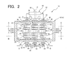
Fig. 2 is a cross sectional view taken along a line A-A inFig. 1 ; -
Fig. 3 is a fragmentary cross sectional view taken along a line B-B inFig. 2 ; -
Fig. 4 is a fragmentary cross sectional view taken along a line C-C inFig. 2 ; -
Fig. 5 is a fragmentary cross sectional view taken along a line D-D inFig. 2 ; -
Fig. 6 is an enlarged fragmentary cross sectional view taken along a line E-E inFig. 5 ; -
Fig. 7 is a fragmentary cross sectional view corresponding to that ofFig. 3 and showing an operating state of the pressing machine ofFig. 1 different from that shown inFig. 1 ; -
Fig. 8 is a fragmentary cross sectional view corresponding to that ofFig. 4 and showing the operating state of the pressing machine ofFig. 1 different from that shown inFig. 1 ; -
Fig. 9 is a fragmentary cross sectional view corresponding to a part of the view ofFig. 2 and showing the operating state of the pressing machine ofFig. 1 different from that shown inFig. 1 ; -
Fig. 10 is a schematic cross sectional view corresponding to that ofFig. 2 and showing a pressing machine according to another embodiment of the invention; -
Fig. 11 is a schematic cross sectional view corresponding to that ofFig. 2 and showing a pressing machine according to a further embodiment of the invention. - To clarify the invention more specifically, embodiments of the invention will be described by reference to the drawings.
- Referring first to the front elevational view of
Fig. 1 partly in cross section, there is shown apressing machine 10 according to one embodiment of the invention. Thepressing machine 10 has a one-piece frame 18 consisting of alower portion 12, anintermediate portion 14 and anupper portion 16. Alower die 22 is attached to an upper surface of abolster 20 fixedly mounted on thelower portion 12 of theframe 18, while anupper die 26 is attached to a lower surface of a slider (slide member) 24 disposed within theintermediate portion 14 of theframe 18. Thelower die 22 and theupper die 26 cooperate with each other to constitute a pressing die. Theslider 24 is configured so as to be movable in the vertical direction while being guided by a pair ofslider guides 28 provided in opposition to each other on inner surfaces of theintermediate portion 14 of theframe 18. A plurality of crankshafts 34 (threecrankshafts 34 in this embodiment) each havingmain shaft portions 30 and aneccentric shaft portion 32 are rotatably supported by theupper portion 16 of theframe 18, as described later. - The
slider 24 hasrod portions 36 integrally formed so as to vertically upwardly project from its upper surface, such that therod portions 36 are connected to therespective crankshafts 34 through respective connectingrods 38. More specifically described, each connectingrod 38 is connected at one of its opposite end portions (upper end portion) to theeccentric shaft portion 32 of thecorresponding crankshaft 34 through asleeve 40, and at the other end portion (lower end portion) to an upper end portion of thecorresponding rod portion 36 of theslider 24 through acrank pin 42. The connectingrod 38 is rotatable relative to theeccentric shaft portion 32 and thecrank pin 42, and pivotable about thecrank pin 42. Thus, the pressingmachine 10 is configured to cause a reciprocatory movement of theslider 24 by displacements of theeccentric shaft portions 32 caused by rotary motions of thecrankshafts 34 about respective axes (P) of theirmain shaft portions 30. Along with the reciprocatory movement (movement in downward and upward directions) of theslider 24, theupper die 26 is moved toward and away from thelower die 22, to perform a pressing operation with respect to a workpiece disposed between the upper and lower dies 26 and 22, as in the conventional pressing machine. - The
main shaft portions 30 of eachcrankshaft 34 are disposed coaxially with each other, and rotatably supported by the frame 18 (its upper portion 16) throughrespective bearings 44, as shown inFig. 2 . Accordingly, the axis (P) of eachmain shaft portion 30 serves as an axis of rotation of eachcrankshaft 34. Although not shown inFig. 2 , in this embodiment, theslider 24 is a flat plate having a large thickness and an elongate rectangular shape as seen in its plan view. Accordingly, theupper portion 16 of theframe 18 has an elongate rectangular shape in its cross section taken in a horizontal plane. Thecrankshafts 34 are disposed such that their axial directions are perpendicular to the longitudinal direction of theslider 24, in other words, the axes (P) of rotation of thecrankshafts 34 extend in the transverse direction of theslider 24, and such that thecrankshafts 34 are spaced apart from each other in the longitudinal direction of the slider 24 (upper portion 16 of the frame 18). - The
eccentric shaft portion 32 of eachcrankshaft 34 is disposed between and eccentrically with respect to themain shaft portions 30, such that theeccentric shaft portion 32 extends parallel to themain shaft portions 30, and such that an axis (Q) of theeccentric shaft portion 32 is spaced apart from the axis (P) of themain shaft portions 30 by a predetermined distance (X) in a radial direction of the main shaft portions 30 (in this embodiment, in the left direction as seen inFig. 2 ). The distance (X) between the axis (P) of themain shaft portions 30 and the axis (Q) of theeccentric shaft portion 32 in the radial direction is defined as an eccentricity amount (X) of theeccentric shaft portion 32. Theeccentric shaft portion 32 has a large-diameter portion 32a constituting its axially central portion, and small-diameter portions 32b which are provided on respective opposite sides of the large-diameter portion 32a and which constitute respective opposite end portions of theeccentric shaft portion 32. The large-diameter portion 32a and the small-diameter portions 32b are disposed coaxially with each other. The above-described one end portion of each connectingrod 38 is connected to the large-diameter portion 32a of theeccentric shaft portion 32.Partition plates 46 in the form of small plate pieces are formed integrally with theeccentric shaft portion 32, between the large-diameter portion 32a and the respective small-diameter portions 32b. - In the
pressing machine 10 of this embodiment, the adjacent twocrankshafts 34 are connected to each other by a rotary-driving-force transmission lever 48 (hereinafter referred to as a "transmission lever 48") as a first connection lever in the form of an elongate plate. Eachtransmission lever 48 is rotatably attached to theeccentric shaft portions 32 of therespective crankshafts 34 through respective sleeves 50 (as shown inFigs. 3 and 4 ). - More specifically described, as shown in
Figs. 2 and3 , theleftmost crankshaft 34 and theintermediate crankshaft 34 as seen in those figures are connected to each other at their small-diameter portions 32b provided in one of opposite axial end portions (lower end portions as seen inFig. 2 ) of therespective crankshafts 34, by thetransmission lever 48. On the other hand, as shown inFigs. 2 and4 , therightmost crankshaft 34 and theintermediate crankshaft 34 as seen in those figures are connected to each other at their small-diameter portions 32b provided in the other axial end portions (upper end portions as seen inFig. 2 ) of therespective crankshafts 34, by theother transmission lever 48. Thus, the twotransmission levers 48 are attached to theintermediate crankshaft 34, such that the twotransmission levers 48 are disposed on respective opposite sides of the portion (large-diameter portion 32a) of theintermediate crankshaft 34 connected to the connectingrod 38, as seen in the axial direction of theeccentric shaft portion 32 of theintermediate crankshaft 34. Further, the twotransmission levers 48 extend from theeccentric shaft portion 32 of theintermediate crankshaft 34 in respective opposite directions which are perpendicular to the axial direction of theeccentric shaft portion 32 and parallel to a plane including the axes (Q) of theeccentric shaft portions 32 of the intermediate, leftmost andrightmost crankshafts 34. - On the other hand, as shown in
Figs. 2 ,5 and 6 ,eccentric levers 52 in the form of plates are each provided on an axial end portion (lower end portion as seen inFig. 2 ) of one of the twomain shaft portions 30 of therespective crankshafts 34, which axial end portion outwardly projects from theupper portion 16 of theframe 18, such that theeccentric levers 52 extend in the same radial direction of themain shaft portions 30, which radial direction is different from the direction of eccentricity of theeccentric shaft portions 32 with respect to themain shaft portions 30. In this embodiment, theeccentric levers 52 extend in an upward direction as seen inFigs. 5 and 6 , such that the direction of extension of theeccentric levers 52 has a phase difference of 90° with respect to the direction of eccentricity of theeccentric shaft portions 32. - Further, pins 54 in the form of small-diameter round rods are integrally provided in distal end portions of the respective
eccentric levers 52, such that thepins 54 project in a direction parallel to the axial direction of themain shaft portions 30. Namely, thepins 54 are disposed eccentrically with respect to themain shaft portions 30, such that thepins 54 extend parallel to themain shaft portions 30, and such that positions of thepins 54 as seen in the circumferential direction of themain shaft portions 30 are different from those of theeccentric shaft portions 32. In this embodiment, as shown inFig. 5 , the direction of eccentricity of theeccentric shaft portions 32 with respect to themain shaft portions 30 and a direction of eccentricity of thepins 54 with respect to themain shaft portions 30 form an angle θ (90° in this embodiment) threrebetween about the axis (P) of themain shaft portions 30. In this respect, it is noted that a distance (Y) from the axis (P) of themain shaft portions 30 to an axis (R) of eachpin 54 in a direction perpendicular to those axes is defined as an eccentricity amount (Y) of thepin 54. The eccentricity amount (Y) is set so as to be larger than the above-described eccentricity amount (X) of theeccentric shaft portion 32. - Further, as is apparent from
Figs. 2 and6 , thepins 54 project from theeccentric levers 52 such that distal end portions of thepins 54 are located axially outwardly of corresponding ends of the respective crankshafts 34 (main shaft portions 30). - A dead-center escape lever 56 (hereinafter referred to as an "
escape lever 56" ) as a second connection lever in the form of an elongate plate is rotatably attached to the distal end portions of thepins 54 throughrespective sleeves 58, as shown inFig. 5 . Thus, the plurality ofcrankshafts 34 are connected to each other at one of their opposite axial end portions by theescape lever 56 through theeccentric levers 52 and thepins 54. - In this embodiment, a
clutch mechanism 60 is integrally assembled with respect to the other axial end portion (upper end portion as seen inFig. 2 ) of theintermediate crankshaft 34, which axial end portion outwardly projects from theupper portion 16 of theframe 18, as shown inFig. 2 , and aflywheel 62 is rotatably supported by the above-described other axial end portion of theintermediate crankshaft 34 through a ball bearing or other mechanism not shown. Thus, in thepressing machine 10 of this embodiment, theintermediate crankshaft 34 among the plurality ofcrankshafts 34 serves as the crankshaft (hereinafter referred to as a "driving crankshaft") which is rotated with a constant-velocity rotary motion of theflywheel 62 transmitted through theclutch mechanism 60. On the other hand, thecrankshafts 34 disposed on the respective opposite sides of the drivingcrankshaft 34 serve as the crankshafts (hereinafter referred to as "driven crankshafts") which are rotated with a rotary driving force received from the drivingcrankshaft 34. - In the
pressing machine 10 constructed as described above, the rotary driving force transmitted to the drivingcrankshaft 34 is further transmitted to the drivencrankshafts 34 mainly through the transmission levers 48, whereby allcrankshafts 34 are rotated in synchronization with each other. - By the way,
Figs. 1-6 show an operating state of thepressing machine 10 at a moment of its operation. At this moment, as shown inFigs. 3 and 4 , theadjacent crankshafts 34 connected to each other by the transmission levers 48 are positioned such that the axes (P) of themain shaft portions 30 of therespective crankshafts 34 and the axes (Q) of theeccentric shaft portions 32 of therespective crankshafts 34 are all located in a common plane (plane which is indicated by an imaginary straight line L inFigs. 3 and 4 and which is perpendicular to the plane ofFigs. 3 and 4 ), and a center line of each of the transmission levers 48 attached to theeccentric shaft portions 32 of therespective crankshafts 34 is also located in the above-described plane. - In the above-described operating state, the driven
crankshafts 34 connected to the drivingcrankshaft 34 by the transmission levers 48 are instantaneously rotatable in both of the clockwise and counterclockwise directions, even where the drivingcrankshaft 34 is rotated in the clockwise direction as seen inFigs. 3 and 4 (as indicated by a thin arrow-ended line in those figures), so that the direction of rotation of the drivencrankshafts 34 is not univocally fixed. Namely, the drivencrankshafts 34 are positioned at the dead center in a mechanism for transmitting the rotary driving force through the transmission levers 48. - On the other hand, at this moment, as shown in
Fig. 5 showing the connection between thecrankshafts 34 and theescape lever 56, the direction of eccentricity of thepins 54 with respect to themain shaft portions 30 and the direction of eccentricity of theeccentric shaft portions 32 with respect to themain shaft portions 30 form the angle θ therebetween. In other words, there is a difference of θ between a rotational phase of the positions (pins 54) at which theescape lever 56 is attached to thecrankshafts 34 and a rotational phase of the positions (eccentric shaft portions 32) at which the transmission levers 48 are attached to thecrankshafts 34. Therefore, a force is applied to the drivencrankshafts 34 by theescape lever 56 such that the drivencrankshafts 34 are rotated in the same direction as the drivingcrankshaft 34. - By application of the force to the driven
crankshafts 34 by theescape lever 56, the drivencrankshafts 34 escape from the dead center in the mechanism for transmitting the rotary driving force through the transmission levers 48. Thus, by cooperating actions of the transmission levers 48 and theescape lever 56, the drivencrankshafts 34 are rotated in synchronization with the drivingcrankshaft 34 in the predetermined direction of rotation of the drivingcrankshaft 34. -
Figs. 7-9 show another moment of rotary motions of thecrankshafts 34, namely, the moment at which theslider 24 is positioned at its bottom dead center. At this moment, the drivingcrankshaft 34 acts so as to press theeccentric shaft portion 32 of the drivencrankshaft 34 disposed on its left side, in the left direction through thetransmission lever 48, so that the above-described drivencrankshaft 34 is rotated, as shown inFig. 7 . As a result, the drivingcrankshaft 34 receives a rightward force (indicated by a blank arrow inFig. 7 ) as a reaction force from thetransmission lever 48. - On the other hand, the driving
crankshaft 34 acts so as to pull theeccentric shaft portion 32 of the drivencrankshaft 34 disposed on its right side, in the left direction through theother transmission lever 48, so that the above-described drivencrankshaft 34 is rotated, as shown inFig. 8 . As a result, the drivingcrankshaft 34 receives a rightward force (indicated by a blank arrow inFig. 8 ) as a reaction force from theother transmission lever 48. As described above, the drivingcrankshaft 34 receives the substantially equal forces in the same direction at its portions disposed on the respective opposite sides of the connectingrod 38, while the drivingcrankshaft 34 is rotated, as shown inFig. 9 . - It will be understood from the foregoing description of this embodiment that the transmission levers 48 as the first connection levers are attached to the
eccentric shaft portions 32 of therespective crankshafts 34, and theescape lever 56 as the second connection lever is attached to thepins 54 which are provided in the axial end portions of therespective crankshafts 34 through theeccentric levers 52, such that the positions of thepins 54 as seen in the circumferential direction of themain shaft portions 30 are different from those of theeccentric shaft portions 32. Accordingly, by the cooperating actions of the transmission levers 48 and theescape lever 56, the rotary driving force transmitted to the drivingcrankshaft 34 can be smoothly transmitted to theother crankshafts 34. - Namely, while the driving
crankshaft 34 is rotated, there is a phase difference between the positions (eccentric shaft portions 32) at which the transmission levers 48 are attached to thecrankshafts 34 and the positions (pins 54) at which theescape lever 56 is attached to thecrankshafts 34. Therefore, even when the drivencrankshafts 34 are positioned at the dead center in the mechanism for transmitting the rotary driving force through the transmission levers 48, the direction of rotation of the drivencrankshafts 34 is univocally fixed by theescape lever 56. Thus, the pressingmachine 10 as a whole does not have an actual dead center when the plurality ofcrankshafts 34 are rotated in synchronization with each other, so that the rotary driving force can be smoothly transmitted among the plurality ofcrankshafts 34. - Further, the pressing
machine 10 of this embodiment requires no gear members, so that thepressing machine 10 is not affected by a large moment of inertia of the gear members, whereby start/stop performance (operating response) of thepressing machine 10 is advantageously improved, and a desired pressing operation can be performed with a high degree of press forming accuracy using thepressing machine 10, and a cycle time required for forming a desired product using thepressing machine 10 can be effectively reduced. Namely, the pressingmachine 10 is configured to directly move the connectingrods 38 by thecrankshafts 34, so that thepressing machine 10 has a high degree of operating response and permits advantageous reduction of the cycle time required for formation of the desired product. - The
pressing machine 10 as a whole has a simplified structure and a reduced number of components, since it requires no gear members, resulting in an advantage of reduction of a cost of its production. - Further, the
eccentric levers 52 are each provided on the axial end portion of the one of the twomain shaft portions 30 of therespective crankshafts 34, which axial end portion outwardly projects from theupper portion 16 of theframe 18, so that there is no need to increase sizes of theupper portion 16 and theframe 18 as a whole, in order to attach theescape lever 56 to thepins 54 projecting from theeccentric levers 52. Accordingly, a distance between themain shaft portions 30 of eachcrankshaft 34 supported by theupper portion 16 of the frame 18 (distance between the bearings 44) is not increased, resulting in an advantage that a high degree of concentricity between themain shaft portions 30 can be easily obtained. - As described above, the
main shaft portions 30 of eachcrankshaft 34 are supported by theupper portion 16 of theframe 18 with a short distance (span) therebetween, so that thecrankshaft 34 effectively exhibits a sufficiently high strength to resist to its flexural deformation. Namely, in thecrankshaft 34, a large force (reaction force) is applied from thetransmission lever 48 to theeccentric shaft portion 32 which is disposed between themain shaft portions 30 within theupper portion 16 of theframe 18. However, theeccentric shaft portion 32 is disposed between themain shaft portions 30 supported with the above-indicated short span, so that a risk of flexural deformation of theeccentric shaft portion 32 is advantageously reduced. As a result, the weight (diameter) of thecrankshaft 34 can be reduced to further reduce a moment of inertia of thecrankshaft 34, whereby the operating response of thepressing machine 10 and accuracy of synchronization of the rotary motions of thecrankshafts 34 can be improved, and the cycle time required for forming the desired product using thepressing machine 10 can be further reduced. - Further, the
escape lever 56 is attached to the distal end portions of therespective pins 54 which project from theeccentric levers 52 such that their distal end portions are located axially outwardly of the corresponding ends of therespective crankshafts 34, so that an interference between theescape lever 56 and thecrankshafts 34 can be advantageously prevented. - Even where the
slider 24 has the elongate rectangular shape as seen in its plan view in order to permit a pressing operation with respect to a workpiece having a large width, the plurality ofcrankshafts 34 can be disposed such that their axial directions are perpendicular to the longitudinal direction of the slider 24 (i.e., the axial directions of thecrankshafts 34 extend in the transverse direction of the slider 24), and such that thecrankshafts 34 are spaced apart from each other in the longitudinal direction of theslider 24. Accordingly, the distance between themain shaft portions 30 of each of the crankshafts 34(distance between the bearings 44) is not increased, so that a high degree of concentricity between themain shaft portions 30 can be easily obtained, and thecrankshafts 34 can be easily produced. - In the above-described embodiment, the eccentricity amount (Y) of each
pin 54 with respect to themain shaft portions 30 is set so as to be larger than the eccentricity amount (X) of theeccentric shaft portion 32. Namely, the distance (Y) from the axis (P) of themain shaft portions 30 to the axis (R) of thepin 54 is larger than the distance (X) from the axis (P) of themain shaft portions 30 to the axis (Q) of theeccentric shaft portion 32. In this respect, it is noted that during the rotary motions of thecrankshafts 34, the axis (P) of themain shaft portions 30 serves as the fulcrum point, and the axis (R) of thepin 54 serves as a point of action. Since the distance (Y) is set so as to be larger than the distance (X) as described above, a force (load) applied to thepins 54 and theescape lever 56 during the rotary motions of thecrankshafts 34 is smaller than that applied to the transmission levers 48. Accordingly, theescape lever 56 can have a thickness smaller than that of the transmission levers 48. Further, the diameter of thepins 54 and the thickness of theescape lever 56 can be reduced to reduce their weights and the moment of inertia. - In the above-described embodiment, the plurality of transmission levers 48 are provided, and the
eccentric shaft portions 32 of theadjacent crankshafts 34 are connected to each other by each of the plurality of transmission levers 48. Further, the twotransmission levers 48 are attached to the crankshaft 34 (drivingcrankshaft 34 in the above-described embodiment) interposed between the other twocrankshafts 34, such that the twotransmission levers 48 are disposed on the respective opposite sides of the portion (large-diameter portion 32a) of the drivingcrankshaft 34 connected to the connectingrod 38, as seen in the axial direction of theeccentric shaft portion 32 of the drivingcrankshaft 34. Further, the twotransmission levers 48 extend from theeccentric shaft portion 32 of the drivingcrankshaft 34 in respective opposite directions which are perpendicular to the axial direction of theeccentric shaft portion 32 and parallel to the plane including the axes (Q) of theeccentric shaft portions 32 of the drivingcrankshaft 34 and the other twocrankshafts 34. Therefore, the two forces applied from the twotransmission levers 48 to the respective two axial portions of the drivingcrankshaft 34 in the direction perpendicular to its axial direction are balanced with respect to each other, so that the two forces do not act on the drivingcrankshaft 34 so as to cause inclination of its axis (P). Accordingly, flexure of the drivingcrankshaft 34 or inclination of its axis is prevented, and a high degree of concentricity of itsmain shaft portions 30 is assured, whereby the drivingcrankshaft 34 can be more smoothly rotated. - A
pressing machine 64 having a structure according to another embodiment of the invention is shown in the cross sectional view ofFig. 10 corresponding to that ofFig. 2 . The reference signs used to denote the members and portions of thepressing machine 10 are used to denote the corresponding members and portions of thepressing machine 64 shown inFig. 10 , which will not be described redundantly. - The
pressing machine 64 shown inFig. 10 has a structure in which the plurality ofcrankshafts 34 are connected to each other by asingle transmission lever 48. In thepressing machine 64 constructed as described above, the rotary driving force transmitted to the drivingcrankshaft 34 can be smoothly transmitted to the drivencrankshafts 34 by the cooperating actions of thetransmission lever 48 and theescape lever 56, as in thepressing machine 10 of the above-described embodiment. - In this
pressing machine 64, theeccentric shaft portion 32 of eachcrankshaft 34 is formed such that a direction of eccentricity of the large-diameter portion 32a and a direction of eccentricity of the small-diameter portions 32b are opposite to each other. Namely, during the rotatory motion of thecrankshaft 34, there is a phase difference of 180° between the large-diameter portion 32a and the small-diameter portions 32b. Thepressing machine 64 constructed as described above has a characteristic that where known dynamic balances (not shown) are connected to the small-diameter portions 32b which are not connected to thetransmission lever 48, vibration of theslider 24 caused along with its reciprocatory movement can be offset to reduce vibration of thepressing machine 64 as a whole. - Although the representative embodiments of the invention have been described for illustrative purpose only, it is to be understood that the invention is by no means limited to the details of the illustrated embodiments.
- The position of each
pin 54 relative to the position of theeccentric shaft portion 32 as seen in the circumferential direction of themain shaft portions 30 is not limited to that in the above-described embodiments. Namely, the angle θ formed between the direction of eccentricity of theeccentric shaft portions 32 with respect to themain shaft portions 30 and the direction of eccentricity of thepins 54 with respect to themain shaft portions 30 is not limited, as long as the angle θ is not 0° and 180°. In the cases where the angle θ is 0° and 180°, the positions (eccentric shaft portions 32) at which thetransmission lever 48 is attached to thecrankshafts 34 and the positions (pins 54) at which theescape lever 56 is attached to thecrankshafts 34 reach the dead center at the same time, so that thetransmission lever 48 and theescape lever 56 cannot cooperate with each other to allow the drivencrankshafts 34 to advantageously escape from the dead center. The angle θ is preferably set at 90°, so that there is a phase difference of 90° between thepins 54 and theeccentric shaft portions 32, as seen in the direction of rotation of thecrankshafts 34. - The number of the
crankshafts 34 is not limited to that in the above-described embodiments, as long as a plurality of crankshafts 34 (at least two crankshafts) are provided.Fig. 11 shows apressing machine 66 having fourcrankshafts 34. Thepressing machine 66 is provided with threetransmission levers 48, namely, afirst transmission lever 48 connecting two adjacent ones of the fourcrankshafts 34, asecond transmission lever 48 connecting the other twoadjacent crankshafts 34, and athird transmission lever 48 connecting the two adjacentinner crankshafts 34. The first and third transmission levers 48 are disposed on respective opposite sides of the large-diameter portion 32a of one of the two adjacentinner crankshafts 34, as seen in the axial direction of theeccentric shaft portion 32 of thatcrankshaft 34. Further, the first and third transmission levers 48 extend from theeccentric shaft portion 32 of the above-indicated one inner crankshaft 34 (driving crankshaft 34) in respective opposite directions which are perpendicular to the axial direction of theeccentric shaft portion 32 and parallel to a plane including the axes (Q) of theeccentric shaft portions 32 of the above-indicated twoadjacent crankshafts 34 and the above-indicated oneinner crankshaft 34. The second and third transmission levers 48 are disposed on respective opposite sides of the large-diameter portion 32a of the other of the two adjacentinner crankshafts 34, as seen in the axial direction of theeccentric shaft portion 32 of thatcrankshaft 34. Further, the second and third transmission levers 48 extend from theeccentric shaft portion 32 of the above-indicated other inner crankshaft 34 (driven crankshaft 34) in respective opposite directions which are perpendicular to the axial direction of theeccentric shaft portion 32 and parallel to a plane including the axes (Q) of theeccentric shaft portions 32 of the above-indicated other two adjacent crankshafts and the above-indicated otherinner crankshaft 34. Accordingly, not only the flexure of the drivingcrankshaft 34 is advantageously prevented, as in the above-described embodiment, but also flexure of the driven crankshaft 34 (thesecond crankshaft 34 as seen from the left inFig. 11 ) interposed between the drivingcrankshaft 34 and theleftmost crankshaft 34 is advantageously prevented. - The direction of extension of the
eccentric levers 52 and their form are not limited to those in the above-described embodiments. Theeccentric levers 52 may take the form of "L" having a bent intermediate portion, for example. Namely, it suffices that the positions of thepins 54 integrally formed with the respectiveeccentric levers 52 are different from the positions of theeccentric shaft portions 32 as seen in the circumferential direction of themain shaft portions 30. - Various known mechanisms may be employed as the mechanism for transmitting the rotary driving force to the driving
crankshaft 34. It is possible to provide such mechanism in the same axial end portion of thecrankshaft 34 as theescape lever 56, depending on the structure of the mechanism. - It is to be understood that the present invention may be embodied with various changes, modifications and improvements, which may occur to those skilled in the art, without departing from the spirit and scope of the invention, and that such changes, modifications, and improvements are also within the scope of the invention.
NOMENCLATURE OF REFERENCE SIGNS 10, 64, 66: Pressing machine 18: Frame 24: Slider 30: Main shaft portion 32: Eccentric shaft portion 32a: Large- diameter portion 32b: Small-diameter portion 34: Crankshaft 38: Connecting rod 48: Transmission lever 52: Eccentric lever 54: Pin 56: Escape lever 60: Clutch mechanism 62: Flywheel P: Axis of main shaft portions Q: Axis of eccentric shaft portion R: Axis of pin L: Imaginary straight line
Claims (8)
- A pressing machine (10, 64, 66) comprising:a plurality of crankshafts (34) each of which has two co-axially disposed main shaft portions (30) and an eccentric shaft portion (32) disposed between and eccentrically with respect to the two main shaft portions (30), and which are rotatably supported at their main shaft portions (30) by a frame (18), such that their axial directions are parallel to each other, and such that they are spaced apart from each other with a predetermined distance therebetween;connecting rods (38) connected at one of their opposite end portions to the eccentric shaft portions (32) of said plurality of crankshafts (34);a slider (24) connected to the other end portions of said connecting rods (38), and reciprocated by displacements of said eccentric shaft portions (32) caused by rotary motions of said plurality of crankshafts (34) about respective axes of their main shaft portions (30);at least one first connection lever (48) attached to said eccentric shaft portions (32) of said plurality of crankshafts (34), for transmitting a rotary driving force transmitted to one of said plurality of crankshafts (34) to another of the plurality of crankshafts (34), so that the plurality of crankshafts (34) are rotated in synchronization with each other;eccentric levers (52) each provided on an axial end portion of one of said two main shaft portions (30) of the respective crankshafts (34), which axial end portion outwardly projects from said frame (18), such that the eccentric levers (52) extend in a direction perpendicular to axial directions of said main shaft portions (30);pins (54) provided so as to project from the respective eccentric levers (52) in a direction parallel to the axial directions of said main shaft portions (30), and such that positions of the pins (54) as seen in a circumferential direction of said main shaft portions (30) are different from those of said eccentric shaft portions (32), and such that distal end portions of the pins (54) are located axially outwardly of corresponding ends of the respective crankshafts (34); anda second connection lever (56) attached to said distal end portions of the respective pins (54),whereby said rotary driving force is smoothly transmitted to said another of the plurality of crankshafts (34) by cooperating actions of said at least one first connection lever (48) and said second connection lever (56).
- The pressing machine (10, 64, 66) according to claim 1, wherein said eccentric shaft portions (32) and said pins (54) have a phase difference of 90° therebetween during the rotary motions of said crankshafts (34) about the respective axes of their main shaft portions (30).
- The pressing machine (10, 64, 66) according to claim 1 or 2, wherein an eccentricity amount of an axis of each of said pins (54) with respect to the axis of said main shaft portions (30) is larger than an eccentricity amount of an axis of said eccentric shaft portion (32) with respect to the axis of said main shaft portions (30).
- The pressing machine (10, 64, 66) according to any one of claims 1 to 3, wherein said second connection lever (56) has a thickness smaller than that of said at least one first connection lever (48).
- The pressing machine (10, 66) according to any one of claims 1 to 4, wherein said at least one first connection lever (48) comprises a plurality of first connection levers (48) each connecting said eccentric shaft portions (32) of adjacent ones of said plurality of crankshafts (34) to each other, and
the plurality of first connection levers (48) comprise two first connection levers (48) which are disposed on respective opposite sides of a portion of the eccentric shaft portion (32) of one of the plurality of crankshafts (34) connected to corresponding one of said connecting rods (38), as seen in an axial direction of the eccentric shaft portion (32), and extend from the eccentric shaft portion (32) of said one crankshaft (34) in respective opposite directions which are perpendicular to the axial direction of the eccentric shaft portion (32) and parallel to a plane including axes of the eccentric shaft portions (32) of said one crankshaft (34) and two other crankshafts (34) disposed on respective opposite sides of said one crankshaft (34). - The pressing machine (10, 66) according to any one of claims 1 to 4, wherein said one of the plurality of crankshafts (34) to which said rotary driving force is transmitted is interposed between two other crankshafts (34) which are rotated with said rotary driving force received from said one of the plurality of crankshafts (34), and
said at least one first connection lever (48) comprises two first connection levers (48) connecting the eccentric shaft portion (32) of said one of the plurality of crankshafts (34) respectively to the eccentric shaft portions (32) of said two other crankshafts (34), and
wherein said two first connection levers (48) are attached to said one of the plurality of crankshafts (34), such that the two first connection levers (48) are disposed on respective opposite sides of a portion of the eccentric shaft portion (32) of said one crankshaft (34) connected to corresponding one of said connecting rods (38), as seen in an axial direction of the eccentric shaft portion (32), and extend from the eccentric shaft portion (32) of said one crankshaft (34) in respective opposite directions which are perpendicular to the axial direction of the eccentric shaft portion (32) and parallel to a plane including axes of the eccentric shaft portions (32) of said one crankshaft (34) and said two other crankshafts (34). - The pressing machine (10, 64, 66) according to any one of claims 1 to 6, wherein said eccentric shaft portion (32) has a large-diameter portion (32a) and at least one small-diameter portion (32b) which has a diameter smaller than that of the large-diameter portion (32a) and which is formed co-axially with the large-diameter portion (32a), and said one end portion of each of said connecting rods (38) is connected to the large-diameter portion (32a), while said at least one first connection lever (48) is attached to the at least one small-diameter portion (32b).
- The pressing machine (10, 64, 66) according to any one of claims 1 to 7, wherein said slider (24) has an elongate rectangular shape as seen in its plan view, and said plurality of crankshafts (34) are disposed such that their axial directions are perpendicular to a longitudinal direction of the slider (24), and such that they are spaced apart from each other in the longitudinal direction of the slider (24).
Applications Claiming Priority (1)
| Application Number | Priority Date | Filing Date | Title |
|---|---|---|---|
| JP2015004765A JP5767416B1 (en) | 2015-01-14 | 2015-01-14 | Press machine |
Publications (3)
| Publication Number | Publication Date |
|---|---|
| EP3045302A1 true EP3045302A1 (en) | 2016-07-20 |
| EP3045302B1 EP3045302B1 (en) | 2017-06-07 |
| EP3045302B8 EP3045302B8 (en) | 2017-08-16 |
Family
ID=53888057
Family Applications (1)
| Application Number | Title | Priority Date | Filing Date |
|---|---|---|---|
| EP15002851.2A Active EP3045302B8 (en) | 2015-01-14 | 2015-10-06 | Pressing machine |
Country Status (3)
| Country | Link |
|---|---|
| EP (1) | EP3045302B8 (en) |
| JP (1) | JP5767416B1 (en) |
| CN (1) | CN105774010B (en) |
Cited By (1)
| Publication number | Priority date | Publication date | Assignee | Title |
|---|---|---|---|---|
| WO2024074229A1 (en) * | 2022-10-03 | 2024-04-11 | Andritz Technology And Asset Management Gmbh | Press having at least two eccentric shafts |
Families Citing this family (3)
| Publication number | Priority date | Publication date | Assignee | Title |
|---|---|---|---|---|
| CN106976261B (en) * | 2017-05-05 | 2018-12-21 | 桐乡市凯盛精密机械有限公司 | A kind of press machine |
| CN113664096B (en) * | 2020-05-15 | 2023-07-14 | 久恩企业股份有限公司 | Feed cam stop block of screen punching machine |
| JP7461653B2 (en) | 2021-06-08 | 2024-04-04 | 株式会社山田ドビー | Press Machine |
Citations (4)
| Publication number | Priority date | Publication date | Assignee | Title |
|---|---|---|---|---|
| JPS5253476U (en) | 1975-10-15 | 1977-04-16 | ||
| JPS63235098A (en) * | 1987-03-23 | 1988-09-30 | Ishikawajima Harima Heavy Ind Co Ltd | Device for driving press |
| JPH09155595A (en) | 1995-12-05 | 1997-06-17 | Yamada Dobby Co Ltd | Press machine |
| WO2011012290A1 (en) * | 2009-07-29 | 2011-02-03 | Dieffenbacher Gmbh + Co. Kg | Press having a direct-driven crank drive |
Family Cites Families (6)
| Publication number | Priority date | Publication date | Assignee | Title |
|---|---|---|---|---|
| JPS6447904U (en) * | 1987-09-18 | 1989-03-24 | ||
| US5557959A (en) * | 1994-07-25 | 1996-09-24 | Livernois Research & Development Company | Modular die transfer system |
| CN100581801C (en) * | 2002-05-01 | 2010-01-20 | 村田机械株式会社 | Motor-driven lever type press |
| JP4313816B2 (en) * | 2006-12-27 | 2009-08-12 | 株式会社山田ドビー | Press machine |
| JP5412185B2 (en) * | 2009-06-22 | 2014-02-12 | 株式会社山田ドビー | Press machine |
| CN102632637A (en) * | 2012-04-11 | 2012-08-15 | 济南二机床集团有限公司 | Press machine driven by servo motor |
-
2015
- 2015-01-14 JP JP2015004765A patent/JP5767416B1/en active Active
- 2015-10-06 EP EP15002851.2A patent/EP3045302B8/en active Active
- 2015-11-26 CN CN201510845854.4A patent/CN105774010B/en active Active
Patent Citations (5)
| Publication number | Priority date | Publication date | Assignee | Title |
|---|---|---|---|---|
| JPS5253476U (en) | 1975-10-15 | 1977-04-16 | ||
| JPS63235098A (en) * | 1987-03-23 | 1988-09-30 | Ishikawajima Harima Heavy Ind Co Ltd | Device for driving press |
| JPH09155595A (en) | 1995-12-05 | 1997-06-17 | Yamada Dobby Co Ltd | Press machine |
| US5720201A (en) * | 1995-12-05 | 1998-02-24 | Kabushiki Kaisha Yamada Dobby | Pressing machine |
| WO2011012290A1 (en) * | 2009-07-29 | 2011-02-03 | Dieffenbacher Gmbh + Co. Kg | Press having a direct-driven crank drive |
Cited By (1)
| Publication number | Priority date | Publication date | Assignee | Title |
|---|---|---|---|---|
| WO2024074229A1 (en) * | 2022-10-03 | 2024-04-11 | Andritz Technology And Asset Management Gmbh | Press having at least two eccentric shafts |
Also Published As
| Publication number | Publication date |
|---|---|
| JP5767416B1 (en) | 2015-08-19 |
| CN105774010A (en) | 2016-07-20 |
| CN105774010B (en) | 2017-11-24 |
| JP2016129899A (en) | 2016-07-21 |
| EP3045302B8 (en) | 2017-08-16 |
| EP3045302B1 (en) | 2017-06-07 |
Similar Documents
| Publication | Publication Date | Title |
|---|---|---|
| EP3045302B1 (en) | Pressing machine | |
| US7882721B2 (en) | Container bodymaker | |
| US5467706A (en) | Mechanical pressing machine with dynamic balancing device | |
| US20180029104A1 (en) | Stamping press arrangement | |
| JP5847974B1 (en) | Press machine | |
| JP6446350B2 (en) | Press machine | |
| JP4121353B2 (en) | Material feeder | |
| JP5412185B2 (en) | Press machine | |
| CN2925854Y (en) | Double-spot and range-variable beading machine | |
| US3888104A (en) | Forging machine | |
| JP4291896B2 (en) | Press machine | |
| CN208410822U (en) | A kind of press machine of Multipoint Drive force | |
| CN109203536B (en) | Double-lever high-speed precision punch mechanism | |
| US5605096A (en) | Mechanical pressing machine with dynamic balancing device | |
| JPH0760490A (en) | Mechanical press apparatus | |
| KR100343056B1 (en) | Press | |
| EP3308949B1 (en) | Dynamic balance device of press machine | |
| US3835689A (en) | Device for corrugation of strips | |
| JP7461653B2 (en) | Press Machine | |
| KR100458711B1 (en) | Crank press having two steps of crank axis | |
| CN203009761U (en) | Double-rocker transmission chain structure | |
| CN116787837A (en) | Compact structure's press | |
| JP2006110591A (en) | Material feeder | |
| RU2197391C1 (en) | Power press drive | |
| JP2003230986A (en) | Press device |
Legal Events
| Date | Code | Title | Description |
|---|---|---|---|
| PUAI | Public reference made under article 153(3) epc to a published international application that has entered the european phase |
Free format text: ORIGINAL CODE: 0009012 |
|
| 17P | Request for examination filed |
Effective date: 20151015 |
|
| AK | Designated contracting states |
Kind code of ref document: A1 Designated state(s): AL AT BE BG CH CY CZ DE DK EE ES FI FR GB GR HR HU IE IS IT LI LT LU LV MC MK MT NL NO PL PT RO RS SE SI SK SM TR |
|
| AX | Request for extension of the european patent |
Extension state: BA ME |
|
| GRAP | Despatch of communication of intention to grant a patent |
Free format text: ORIGINAL CODE: EPIDOSNIGR1 |
|
| INTG | Intention to grant announced |
Effective date: 20170220 |
|
| RIN1 | Information on inventor provided before grant (corrected) |
Inventor name: HATTORI, RYUICHI Inventor name: YOSHIDA, AKIHIRO |
|
| GRAS | Grant fee paid |
Free format text: ORIGINAL CODE: EPIDOSNIGR3 |
|
| AK | Designated contracting states |
Kind code of ref document: B1 Designated state(s): AL AT BE BG CH CY CZ DE DK EE ES FI FR GB GR HR HU IE IS IT LI LT LU LV MC MK MT NL NO PL PT RO RS SE SI SK SM TR |
|
| REG | Reference to a national code |
Ref country code: GB Ref legal event code: FG4D |
|
| GRAA | (expected) grant |
Free format text: ORIGINAL CODE: 0009210 |
|
| REG | Reference to a national code |
Ref country code: CH Ref legal event code: EP Ref country code: AT Ref legal event code: REF Ref document number: 898916 Country of ref document: AT Kind code of ref document: T Effective date: 20170615 |
|
| REG | Reference to a national code |
Ref country code: IE Ref legal event code: FG4D |
|
| REG | Reference to a national code |
Ref country code: DE Ref legal event code: R096 Ref document number: 602015002944 Country of ref document: DE |
|
| REG | Reference to a national code |
Ref country code: CH Ref legal event code: NV Representative=s name: PATENTANWAELTE SCHAAD, BALASS, MENZL AND PARTN, CH |
|
| RIN2 | Information on inventor provided after grant (corrected) |
Inventor name: HATTORI, RYUICHI Inventor name: YOSHIDA, AKIHIRO |
|
| REG | Reference to a national code |
Ref country code: NL Ref legal event code: MP Effective date: 20170607 |
|
| REG | Reference to a national code |
Ref country code: LT Ref legal event code: MG4D |
|
| PG25 | Lapsed in a contracting state [announced via postgrant information from national office to epo] |
Ref country code: NO Free format text: LAPSE BECAUSE OF FAILURE TO SUBMIT A TRANSLATION OF THE DESCRIPTION OR TO PAY THE FEE WITHIN THE PRESCRIBED TIME-LIMIT Effective date: 20170907 Ref country code: FI Free format text: LAPSE BECAUSE OF FAILURE TO SUBMIT A TRANSLATION OF THE DESCRIPTION OR TO PAY THE FEE WITHIN THE PRESCRIBED TIME-LIMIT Effective date: 20170607 Ref country code: LT Free format text: LAPSE BECAUSE OF FAILURE TO SUBMIT A TRANSLATION OF THE DESCRIPTION OR TO PAY THE FEE WITHIN THE PRESCRIBED TIME-LIMIT Effective date: 20170607 Ref country code: ES Free format text: LAPSE BECAUSE OF FAILURE TO SUBMIT A TRANSLATION OF THE DESCRIPTION OR TO PAY THE FEE WITHIN THE PRESCRIBED TIME-LIMIT Effective date: 20170607 Ref country code: GR Free format text: LAPSE BECAUSE OF FAILURE TO SUBMIT A TRANSLATION OF THE DESCRIPTION OR TO PAY THE FEE WITHIN THE PRESCRIBED TIME-LIMIT Effective date: 20170908 Ref country code: HR Free format text: LAPSE BECAUSE OF FAILURE TO SUBMIT A TRANSLATION OF THE DESCRIPTION OR TO PAY THE FEE WITHIN THE PRESCRIBED TIME-LIMIT Effective date: 20170607 |
|
| REG | Reference to a national code |
Ref country code: AT Ref legal event code: MK05 Ref document number: 898916 Country of ref document: AT Kind code of ref document: T Effective date: 20170607 |
|
| PG25 | Lapsed in a contracting state [announced via postgrant information from national office to epo] |
Ref country code: BG Free format text: LAPSE BECAUSE OF FAILURE TO SUBMIT A TRANSLATION OF THE DESCRIPTION OR TO PAY THE FEE WITHIN THE PRESCRIBED TIME-LIMIT Effective date: 20170907 Ref country code: NL Free format text: LAPSE BECAUSE OF FAILURE TO SUBMIT A TRANSLATION OF THE DESCRIPTION OR TO PAY THE FEE WITHIN THE PRESCRIBED TIME-LIMIT Effective date: 20170607 Ref country code: RS Free format text: LAPSE BECAUSE OF FAILURE TO SUBMIT A TRANSLATION OF THE DESCRIPTION OR TO PAY THE FEE WITHIN THE PRESCRIBED TIME-LIMIT Effective date: 20170607 Ref country code: LV Free format text: LAPSE BECAUSE OF FAILURE TO SUBMIT A TRANSLATION OF THE DESCRIPTION OR TO PAY THE FEE WITHIN THE PRESCRIBED TIME-LIMIT Effective date: 20170607 Ref country code: SE Free format text: LAPSE BECAUSE OF FAILURE TO SUBMIT A TRANSLATION OF THE DESCRIPTION OR TO PAY THE FEE WITHIN THE PRESCRIBED TIME-LIMIT Effective date: 20170607 |
|
| PG25 | Lapsed in a contracting state [announced via postgrant information from national office to epo] |
Ref country code: SK Free format text: LAPSE BECAUSE OF FAILURE TO SUBMIT A TRANSLATION OF THE DESCRIPTION OR TO PAY THE FEE WITHIN THE PRESCRIBED TIME-LIMIT Effective date: 20170607 Ref country code: AT Free format text: LAPSE BECAUSE OF FAILURE TO SUBMIT A TRANSLATION OF THE DESCRIPTION OR TO PAY THE FEE WITHIN THE PRESCRIBED TIME-LIMIT Effective date: 20170607 Ref country code: EE Free format text: LAPSE BECAUSE OF FAILURE TO SUBMIT A TRANSLATION OF THE DESCRIPTION OR TO PAY THE FEE WITHIN THE PRESCRIBED TIME-LIMIT Effective date: 20170607 Ref country code: RO Free format text: LAPSE BECAUSE OF FAILURE TO SUBMIT A TRANSLATION OF THE DESCRIPTION OR TO PAY THE FEE WITHIN THE PRESCRIBED TIME-LIMIT Effective date: 20170607 Ref country code: CZ Free format text: LAPSE BECAUSE OF FAILURE TO SUBMIT A TRANSLATION OF THE DESCRIPTION OR TO PAY THE FEE WITHIN THE PRESCRIBED TIME-LIMIT Effective date: 20170607 |
|
| PG25 | Lapsed in a contracting state [announced via postgrant information from national office to epo] |
Ref country code: SM Free format text: LAPSE BECAUSE OF FAILURE TO SUBMIT A TRANSLATION OF THE DESCRIPTION OR TO PAY THE FEE WITHIN THE PRESCRIBED TIME-LIMIT Effective date: 20170607 Ref country code: PL Free format text: LAPSE BECAUSE OF FAILURE TO SUBMIT A TRANSLATION OF THE DESCRIPTION OR TO PAY THE FEE WITHIN THE PRESCRIBED TIME-LIMIT Effective date: 20170607 Ref country code: IT Free format text: LAPSE BECAUSE OF FAILURE TO SUBMIT A TRANSLATION OF THE DESCRIPTION OR TO PAY THE FEE WITHIN THE PRESCRIBED TIME-LIMIT Effective date: 20170607 Ref country code: IS Free format text: LAPSE BECAUSE OF FAILURE TO SUBMIT A TRANSLATION OF THE DESCRIPTION OR TO PAY THE FEE WITHIN THE PRESCRIBED TIME-LIMIT Effective date: 20171007 |
|
| REG | Reference to a national code |
Ref country code: DE Ref legal event code: R097 Ref document number: 602015002944 Country of ref document: DE |
|
| PLBE | No opposition filed within time limit |
Free format text: ORIGINAL CODE: 0009261 |
|
| STAA | Information on the status of an ep patent application or granted ep patent |
Free format text: STATUS: NO OPPOSITION FILED WITHIN TIME LIMIT |
|
| PG25 | Lapsed in a contracting state [announced via postgrant information from national office to epo] |
Ref country code: DK Free format text: LAPSE BECAUSE OF FAILURE TO SUBMIT A TRANSLATION OF THE DESCRIPTION OR TO PAY THE FEE WITHIN THE PRESCRIBED TIME-LIMIT Effective date: 20170607 |
|
| 26N | No opposition filed |
Effective date: 20180308 |
|
| PG25 | Lapsed in a contracting state [announced via postgrant information from national office to epo] |
Ref country code: MC Free format text: LAPSE BECAUSE OF FAILURE TO SUBMIT A TRANSLATION OF THE DESCRIPTION OR TO PAY THE FEE WITHIN THE PRESCRIBED TIME-LIMIT Effective date: 20170607 |
|
| REG | Reference to a national code |
Ref country code: IE Ref legal event code: MM4A |
|
| REG | Reference to a national code |
Ref country code: FR Ref legal event code: ST Effective date: 20180629 |
|
| PG25 | Lapsed in a contracting state [announced via postgrant information from national office to epo] |
Ref country code: LU Free format text: LAPSE BECAUSE OF NON-PAYMENT OF DUE FEES Effective date: 20171006 |
|
| REG | Reference to a national code |
Ref country code: BE Ref legal event code: MM Effective date: 20171031 |
|
| PG25 | Lapsed in a contracting state [announced via postgrant information from national office to epo] |
Ref country code: BE Free format text: LAPSE BECAUSE OF NON-PAYMENT OF DUE FEES Effective date: 20171031 Ref country code: FR Free format text: LAPSE BECAUSE OF NON-PAYMENT OF DUE FEES Effective date: 20171031 |
|
| PG25 | Lapsed in a contracting state [announced via postgrant information from national office to epo] |
Ref country code: MT Free format text: LAPSE BECAUSE OF NON-PAYMENT OF DUE FEES Effective date: 20171006 |
|
| PG25 | Lapsed in a contracting state [announced via postgrant information from national office to epo] |
Ref country code: IE Free format text: LAPSE BECAUSE OF NON-PAYMENT OF DUE FEES Effective date: 20171006 |
|
| PG25 | Lapsed in a contracting state [announced via postgrant information from national office to epo] |
Ref country code: HU Free format text: LAPSE BECAUSE OF FAILURE TO SUBMIT A TRANSLATION OF THE DESCRIPTION OR TO PAY THE FEE WITHIN THE PRESCRIBED TIME-LIMIT; INVALID AB INITIO Effective date: 20151006 |
|
| PG25 | Lapsed in a contracting state [announced via postgrant information from national office to epo] |
Ref country code: SI Free format text: LAPSE BECAUSE OF FAILURE TO SUBMIT A TRANSLATION OF THE DESCRIPTION OR TO PAY THE FEE WITHIN THE PRESCRIBED TIME-LIMIT Effective date: 20170607 |
|
| PG25 | Lapsed in a contracting state [announced via postgrant information from national office to epo] |
Ref country code: CY Free format text: LAPSE BECAUSE OF FAILURE TO SUBMIT A TRANSLATION OF THE DESCRIPTION OR TO PAY THE FEE WITHIN THE PRESCRIBED TIME-LIMIT Effective date: 20170607 |
|
| PG25 | Lapsed in a contracting state [announced via postgrant information from national office to epo] |
Ref country code: MK Free format text: LAPSE BECAUSE OF FAILURE TO SUBMIT A TRANSLATION OF THE DESCRIPTION OR TO PAY THE FEE WITHIN THE PRESCRIBED TIME-LIMIT Effective date: 20170607 |
|
| PG25 | Lapsed in a contracting state [announced via postgrant information from national office to epo] |
Ref country code: TR Free format text: LAPSE BECAUSE OF FAILURE TO SUBMIT A TRANSLATION OF THE DESCRIPTION OR TO PAY THE FEE WITHIN THE PRESCRIBED TIME-LIMIT Effective date: 20170607 |
|
| PG25 | Lapsed in a contracting state [announced via postgrant information from national office to epo] |
Ref country code: PT Free format text: LAPSE BECAUSE OF FAILURE TO SUBMIT A TRANSLATION OF THE DESCRIPTION OR TO PAY THE FEE WITHIN THE PRESCRIBED TIME-LIMIT Effective date: 20170607 |
|
| PG25 | Lapsed in a contracting state [announced via postgrant information from national office to epo] |
Ref country code: AL Free format text: LAPSE BECAUSE OF FAILURE TO SUBMIT A TRANSLATION OF THE DESCRIPTION OR TO PAY THE FEE WITHIN THE PRESCRIBED TIME-LIMIT Effective date: 20170607 |
|
| GBPC | Gb: european patent ceased through non-payment of renewal fee |
Effective date: 20191006 |
|
| PG25 | Lapsed in a contracting state [announced via postgrant information from national office to epo] |
Ref country code: GB Free format text: LAPSE BECAUSE OF NON-PAYMENT OF DUE FEES Effective date: 20191006 |
|
| PGFP | Annual fee paid to national office [announced via postgrant information from national office to epo] |
Ref country code: DE Payment date: 20231016 Year of fee payment: 9 Ref country code: CH Payment date: 20231102 Year of fee payment: 9 |