EP3043834B1 - Coating process for non-conductive substrates and devices made from the coating process - Google Patents
Coating process for non-conductive substrates and devices made from the coating process Download PDFInfo
- Publication number
- EP3043834B1 EP3043834B1 EP14776772.7A EP14776772A EP3043834B1 EP 3043834 B1 EP3043834 B1 EP 3043834B1 EP 14776772 A EP14776772 A EP 14776772A EP 3043834 B1 EP3043834 B1 EP 3043834B1
- Authority
- EP
- European Patent Office
- Prior art keywords
- pulse
- metal layer
- ranging
- series
- fiber reinforced
- Prior art date
- Legal status (The legal status is an assumption and is not a legal conclusion. Google has not performed a legal analysis and makes no representation as to the accuracy of the status listed.)
- Active
Links
Images

Classifications
-
- C—CHEMISTRY; METALLURGY
- C23—COATING METALLIC MATERIAL; COATING MATERIAL WITH METALLIC MATERIAL; CHEMICAL SURFACE TREATMENT; DIFFUSION TREATMENT OF METALLIC MATERIAL; COATING BY VACUUM EVAPORATION, BY SPUTTERING, BY ION IMPLANTATION OR BY CHEMICAL VAPOUR DEPOSITION, IN GENERAL; INHIBITING CORROSION OF METALLIC MATERIAL OR INCRUSTATION IN GENERAL
- C23C—COATING METALLIC MATERIAL; COATING MATERIAL WITH METALLIC MATERIAL; SURFACE TREATMENT OF METALLIC MATERIAL BY DIFFUSION INTO THE SURFACE, BY CHEMICAL CONVERSION OR SUBSTITUTION; COATING BY VACUUM EVAPORATION, BY SPUTTERING, BY ION IMPLANTATION OR BY CHEMICAL VAPOUR DEPOSITION, IN GENERAL
- C23C14/00—Coating by vacuum evaporation, by sputtering or by ion implantation of the coating forming material
- C23C14/22—Coating by vacuum evaporation, by sputtering or by ion implantation of the coating forming material characterised by the process of coating
- C23C14/34—Sputtering
- C23C14/35—Sputtering by application of a magnetic field, e.g. magnetron sputtering
-
- A—HUMAN NECESSITIES
- A61—MEDICAL OR VETERINARY SCIENCE; HYGIENE
- A61L—METHODS OR APPARATUS FOR STERILISING MATERIALS OR OBJECTS IN GENERAL; DISINFECTION, STERILISATION OR DEODORISATION OF AIR; CHEMICAL ASPECTS OF BANDAGES, DRESSINGS, ABSORBENT PADS OR SURGICAL ARTICLES; MATERIALS FOR BANDAGES, DRESSINGS, ABSORBENT PADS OR SURGICAL ARTICLES
- A61L27/00—Materials for grafts or prostheses or for coating grafts or prostheses
- A61L27/14—Macromolecular materials
- A61L27/18—Macromolecular materials obtained otherwise than by reactions only involving carbon-to-carbon unsaturated bonds
-
- A—HUMAN NECESSITIES
- A61—MEDICAL OR VETERINARY SCIENCE; HYGIENE
- A61B—DIAGNOSIS; SURGERY; IDENTIFICATION
- A61B17/00—Surgical instruments, devices or methods
- A61B17/56—Surgical instruments or methods for treatment of bones or joints; Devices specially adapted therefor
- A61B17/58—Surgical instruments or methods for treatment of bones or joints; Devices specially adapted therefor for osteosynthesis, e.g. bone plates, screws or setting implements
- A61B17/68—Internal fixation devices, including fasteners and spinal fixators, even if a part thereof projects from the skin
- A61B17/80—Cortical plates, i.e. bone plates; Instruments for holding or positioning cortical plates, or for compressing bones attached to cortical plates
-
- A—HUMAN NECESSITIES
- A61—MEDICAL OR VETERINARY SCIENCE; HYGIENE
- A61B—DIAGNOSIS; SURGERY; IDENTIFICATION
- A61B17/00—Surgical instruments, devices or methods
- A61B17/56—Surgical instruments or methods for treatment of bones or joints; Devices specially adapted therefor
- A61B17/58—Surgical instruments or methods for treatment of bones or joints; Devices specially adapted therefor for osteosynthesis, e.g. bone plates, screws or setting implements
- A61B17/68—Internal fixation devices, including fasteners and spinal fixators, even if a part thereof projects from the skin
- A61B17/84—Fasteners therefor or fasteners being internal fixation devices
-
- A—HUMAN NECESSITIES
- A61—MEDICAL OR VETERINARY SCIENCE; HYGIENE
- A61F—FILTERS IMPLANTABLE INTO BLOOD VESSELS; PROSTHESES; DEVICES PROVIDING PATENCY TO, OR PREVENTING COLLAPSING OF, TUBULAR STRUCTURES OF THE BODY, e.g. STENTS; ORTHOPAEDIC, NURSING OR CONTRACEPTIVE DEVICES; FOMENTATION; TREATMENT OR PROTECTION OF EYES OR EARS; BANDAGES, DRESSINGS OR ABSORBENT PADS; FIRST-AID KITS
- A61F2/00—Filters implantable into blood vessels; Prostheses, i.e. artificial substitutes or replacements for parts of the body; Appliances for connecting them with the body; Devices providing patency to, or preventing collapsing of, tubular structures of the body, e.g. stents
- A61F2/02—Prostheses implantable into the body
- A61F2/30—Joints
- A61F2/44—Joints for the spine, e.g. vertebrae, spinal discs
-
- A—HUMAN NECESSITIES
- A61—MEDICAL OR VETERINARY SCIENCE; HYGIENE
- A61L—METHODS OR APPARATUS FOR STERILISING MATERIALS OR OBJECTS IN GENERAL; DISINFECTION, STERILISATION OR DEODORISATION OF AIR; CHEMICAL ASPECTS OF BANDAGES, DRESSINGS, ABSORBENT PADS OR SURGICAL ARTICLES; MATERIALS FOR BANDAGES, DRESSINGS, ABSORBENT PADS OR SURGICAL ARTICLES
- A61L27/00—Materials for grafts or prostheses or for coating grafts or prostheses
- A61L27/28—Materials for coating prostheses
- A61L27/30—Inorganic materials
- A61L27/306—Other specific inorganic materials not covered by A61L27/303 - A61L27/32
-
- A—HUMAN NECESSITIES
- A61—MEDICAL OR VETERINARY SCIENCE; HYGIENE
- A61L—METHODS OR APPARATUS FOR STERILISING MATERIALS OR OBJECTS IN GENERAL; DISINFECTION, STERILISATION OR DEODORISATION OF AIR; CHEMICAL ASPECTS OF BANDAGES, DRESSINGS, ABSORBENT PADS OR SURGICAL ARTICLES; MATERIALS FOR BANDAGES, DRESSINGS, ABSORBENT PADS OR SURGICAL ARTICLES
- A61L31/00—Materials for other surgical articles, e.g. stents, stent-grafts, shunts, surgical drapes, guide wires, materials for adhesion prevention, occluding devices, surgical gloves, tissue fixation devices
- A61L31/04—Macromolecular materials
- A61L31/06—Macromolecular materials obtained otherwise than by reactions only involving carbon-to-carbon unsaturated bonds
-
- A—HUMAN NECESSITIES
- A61—MEDICAL OR VETERINARY SCIENCE; HYGIENE
- A61L—METHODS OR APPARATUS FOR STERILISING MATERIALS OR OBJECTS IN GENERAL; DISINFECTION, STERILISATION OR DEODORISATION OF AIR; CHEMICAL ASPECTS OF BANDAGES, DRESSINGS, ABSORBENT PADS OR SURGICAL ARTICLES; MATERIALS FOR BANDAGES, DRESSINGS, ABSORBENT PADS OR SURGICAL ARTICLES
- A61L31/00—Materials for other surgical articles, e.g. stents, stent-grafts, shunts, surgical drapes, guide wires, materials for adhesion prevention, occluding devices, surgical gloves, tissue fixation devices
- A61L31/08—Materials for coatings
- A61L31/082—Inorganic materials
- A61L31/088—Other specific inorganic materials not covered by A61L31/084 or A61L31/086
-
- C—CHEMISTRY; METALLURGY
- C23—COATING METALLIC MATERIAL; COATING MATERIAL WITH METALLIC MATERIAL; CHEMICAL SURFACE TREATMENT; DIFFUSION TREATMENT OF METALLIC MATERIAL; COATING BY VACUUM EVAPORATION, BY SPUTTERING, BY ION IMPLANTATION OR BY CHEMICAL VAPOUR DEPOSITION, IN GENERAL; INHIBITING CORROSION OF METALLIC MATERIAL OR INCRUSTATION IN GENERAL
- C23C—COATING METALLIC MATERIAL; COATING MATERIAL WITH METALLIC MATERIAL; SURFACE TREATMENT OF METALLIC MATERIAL BY DIFFUSION INTO THE SURFACE, BY CHEMICAL CONVERSION OR SUBSTITUTION; COATING BY VACUUM EVAPORATION, BY SPUTTERING, BY ION IMPLANTATION OR BY CHEMICAL VAPOUR DEPOSITION, IN GENERAL
- C23C14/00—Coating by vacuum evaporation, by sputtering or by ion implantation of the coating forming material
- C23C14/22—Coating by vacuum evaporation, by sputtering or by ion implantation of the coating forming material characterised by the process of coating
- C23C14/34—Sputtering
- C23C14/3485—Sputtering using pulsed power to the target
-
- C—CHEMISTRY; METALLURGY
- C23—COATING METALLIC MATERIAL; COATING MATERIAL WITH METALLIC MATERIAL; CHEMICAL SURFACE TREATMENT; DIFFUSION TREATMENT OF METALLIC MATERIAL; COATING BY VACUUM EVAPORATION, BY SPUTTERING, BY ION IMPLANTATION OR BY CHEMICAL VAPOUR DEPOSITION, IN GENERAL; INHIBITING CORROSION OF METALLIC MATERIAL OR INCRUSTATION IN GENERAL
- C23C—COATING METALLIC MATERIAL; COATING MATERIAL WITH METALLIC MATERIAL; SURFACE TREATMENT OF METALLIC MATERIAL BY DIFFUSION INTO THE SURFACE, BY CHEMICAL CONVERSION OR SUBSTITUTION; COATING BY VACUUM EVAPORATION, BY SPUTTERING, BY ION IMPLANTATION OR BY CHEMICAL VAPOUR DEPOSITION, IN GENERAL
- C23C28/00—Coating for obtaining at least two superposed coatings either by methods not provided for in a single one of groups C23C2/00 - C23C26/00 or by combinations of methods provided for in subclasses C23C and C25C or C25D
-
- A—HUMAN NECESSITIES
- A61—MEDICAL OR VETERINARY SCIENCE; HYGIENE
- A61F—FILTERS IMPLANTABLE INTO BLOOD VESSELS; PROSTHESES; DEVICES PROVIDING PATENCY TO, OR PREVENTING COLLAPSING OF, TUBULAR STRUCTURES OF THE BODY, e.g. STENTS; ORTHOPAEDIC, NURSING OR CONTRACEPTIVE DEVICES; FOMENTATION; TREATMENT OR PROTECTION OF EYES OR EARS; BANDAGES, DRESSINGS OR ABSORBENT PADS; FIRST-AID KITS
- A61F2310/00—Prostheses classified in A61F2/28 or A61F2/30 - A61F2/44 being constructed from or coated with a particular material
- A61F2310/00389—The prosthesis being coated or covered with a particular material
- A61F2310/00395—Coating or prosthesis-covering structure made of metals or of alloys
- A61F2310/00407—Coating made of titanium or of Ti-based alloys
-
- A—HUMAN NECESSITIES
- A61—MEDICAL OR VETERINARY SCIENCE; HYGIENE
- A61F—FILTERS IMPLANTABLE INTO BLOOD VESSELS; PROSTHESES; DEVICES PROVIDING PATENCY TO, OR PREVENTING COLLAPSING OF, TUBULAR STRUCTURES OF THE BODY, e.g. STENTS; ORTHOPAEDIC, NURSING OR CONTRACEPTIVE DEVICES; FOMENTATION; TREATMENT OR PROTECTION OF EYES OR EARS; BANDAGES, DRESSINGS OR ABSORBENT PADS; FIRST-AID KITS
- A61F2310/00—Prostheses classified in A61F2/28 or A61F2/30 - A61F2/44 being constructed from or coated with a particular material
- A61F2310/00389—The prosthesis being coated or covered with a particular material
- A61F2310/00395—Coating or prosthesis-covering structure made of metals or of alloys
- A61F2310/00419—Other metals
- A61F2310/00544—Coating made of tantalum or Ta-based alloys
-
- A—HUMAN NECESSITIES
- A61—MEDICAL OR VETERINARY SCIENCE; HYGIENE
- A61L—METHODS OR APPARATUS FOR STERILISING MATERIALS OR OBJECTS IN GENERAL; DISINFECTION, STERILISATION OR DEODORISATION OF AIR; CHEMICAL ASPECTS OF BANDAGES, DRESSINGS, ABSORBENT PADS OR SURGICAL ARTICLES; MATERIALS FOR BANDAGES, DRESSINGS, ABSORBENT PADS OR SURGICAL ARTICLES
- A61L2420/00—Materials or methods for coatings medical devices
- A61L2420/02—Methods for coating medical devices
-
- A—HUMAN NECESSITIES
- A61—MEDICAL OR VETERINARY SCIENCE; HYGIENE
- A61L—METHODS OR APPARATUS FOR STERILISING MATERIALS OR OBJECTS IN GENERAL; DISINFECTION, STERILISATION OR DEODORISATION OF AIR; CHEMICAL ASPECTS OF BANDAGES, DRESSINGS, ABSORBENT PADS OR SURGICAL ARTICLES; MATERIALS FOR BANDAGES, DRESSINGS, ABSORBENT PADS OR SURGICAL ARTICLES
- A61L2430/00—Materials or treatment for tissue regeneration
- A61L2430/02—Materials or treatment for tissue regeneration for reconstruction of bones; weight-bearing implants
-
- A—HUMAN NECESSITIES
- A61—MEDICAL OR VETERINARY SCIENCE; HYGIENE
- A61L—METHODS OR APPARATUS FOR STERILISING MATERIALS OR OBJECTS IN GENERAL; DISINFECTION, STERILISATION OR DEODORISATION OF AIR; CHEMICAL ASPECTS OF BANDAGES, DRESSINGS, ABSORBENT PADS OR SURGICAL ARTICLES; MATERIALS FOR BANDAGES, DRESSINGS, ABSORBENT PADS OR SURGICAL ARTICLES
- A61L2430/00—Materials or treatment for tissue regeneration
- A61L2430/24—Materials or treatment for tissue regeneration for joint reconstruction
-
- A—HUMAN NECESSITIES
- A61—MEDICAL OR VETERINARY SCIENCE; HYGIENE
- A61L—METHODS OR APPARATUS FOR STERILISING MATERIALS OR OBJECTS IN GENERAL; DISINFECTION, STERILISATION OR DEODORISATION OF AIR; CHEMICAL ASPECTS OF BANDAGES, DRESSINGS, ABSORBENT PADS OR SURGICAL ARTICLES; MATERIALS FOR BANDAGES, DRESSINGS, ABSORBENT PADS OR SURGICAL ARTICLES
- A61L2430/00—Materials or treatment for tissue regeneration
- A61L2430/38—Materials or treatment for tissue regeneration for reconstruction of the spine, vertebrae or intervertebral discs
Definitions
- the present invention relates to a coating process using a new process based on high power impulse magnetron sputtering and medical devices made using this process.
- PEEK and related plastics are preferred materials for implants since they excel over conventional plastics due to their mechanical durability.
- a drawback lies in the poor biological integration of these materials' surface. Therefore, a biocompatible coating is an obvious solution with the requirements of strong adhesion, chemical stability, and conformity to the implant surface; the latter is especially important for spinal spacer devices to maintain primary stability.
- HiPIMS High power impulse magnetron sputtering
- HPPMS High power impulse magnetron sputtering
- a novel deposition technology has been published in 1999 by Kousnetzov et al ( V. Kouznetsov, K. Macak, J.M. Schneider, U. Helmersson, I. Petrov, Surf.Coat.Technol. Volume 122, Issue 2-3 (1999) 290-293 ).
- This technique attracted considerable attention in the last ten years, and a large scientific community evolved utilizing this technology, while the few industrial applications are mainly focusing on wear-protective coatings.
- US-A-2012/310368 discloses a method of depositing a valve metal layer onto a polymeric substrate of a surgical implant using high power impulse magnetron sputtering.
- the present disclosure describes novel modifications to the HiPIMS process and medical devices resulting from such novel process.
- the present disclosure provides for a method for manufacturing a surgical implant as defined in claim 1.
- the present disclosure further provides for a method for manufacturing a surgical implant as defined in claim 2.
- the series of pulses are performed in a unipolar mode.
- the series of pulses are performed in a bipolar mode.
- the methods described herein further include the steps of: immersing the surgical implant into simulated body fluid (SBF) for a time period to thereby form a calcium phosphate layer.
- SBF simulated body fluid
- the methods described herein further include the step of converting the metal layer using an anodization process performed in an acidic solution to thereby form a nano-porous exterior surface.
- the methods described herein further include the step of: converting the metal layer using an anodization process with an electrolyte containing Ca and P ions to thereby form a microporous layer containing Ca and P ions.
- the polyaryletherketone (PAEK) is independently selected from polyetherketone (PEK), fiber reinforced PEK, polyetheretherketone (PEEK), fiber reinforced PEEK, polyetherketoneketone (PEKK), fiber reinforced PEKK, polyetheretherketoneketone (PEEKK), fiber reinforced PEEKK, polyetherketoneetherketoneketone (PEKEKK) and fiber reinforced PEKEKK.
- the metal layer is independently selected from Al, Cr, Zr, Nb, Rh, Pd, Ag, W, Pt, Au, Ta or Ti.
- the surgical implant includes cages and spacers; bone anchors; cranial meshes and articulations.
- the present disclosure provides for a new coating process based on HiPIMS that improves upon the basic technique to give improved adhesion and layer quality of a metal disposed onto a polyaryletherketone substrate. It does so by providing excited species at high concentrations during the process that provides excellent adhesion and dense coatings. While standard sputter deposition techniques yield coatings with insufficient adhesion, we have observed that unipolar HiPIMS and even more so bipolar HiPIMS produce metal coatings with improved adhesion. Moreover, we have found that chopped HiPIMS (“c-HiPIMS”) allows tuning various properties of the deposition plasma and hence of the deposited coating itself. This technique may be applied both in unipolar and in bipolar HiPIMS.
- the present disclosure provides for a method for manufacturing a surgical implant as defined in claim 1.
- the present disclosure further provides for a method for manufacturing a surgical implant as defined in claim 2.
- the series of pulses are performed in a unipolar mode.
- the series of pulses are performed in a bipolar mode.
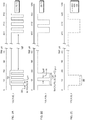
- Figures 1A and 1B illustrate an exemplary method of bipolar HiPIMS pulse sequence, respectively.
- the series of four bipolar pulses are generated using HiPiMS at a repetition frequency of 200 Hz, micro pulse on step of 25 ⁇ s, micro pulse off step of 15 ⁇ s for four micropulses, 110.
- Figure 1B illustrates a prior art bipolar HiPIMS pulse sequence where a single pulse is applied at a repetition frequency of 200 Hz, and a pulse time on of 120 ⁇ s.
- Figures 2A-2B illustrate an exemplary method compared to a prior art HiPIMS pulse sequence illustrated in Figure 2C .
- the series of four micro pulse steps, 210 are generated using c-HiPiMS at a repetition frequency of 200 Hz, micro pulse step on of 25 ⁇ s, and micro pulse step off of 15 ⁇ s.
- the series of two micro pulse steps, 240 are generated using c-HiPiMS at a repetition frequency of 200 Hz, micro pulse step on of 50 ⁇ s, micro pulse step off of 15 ⁇ s.
- a single micro pulse, 280 is generated using HiPiMS at a repetition frequency of 200 Hz.
- the pulse is chopped into a sequence of short single micro pulses each separated by off-times. It was observed that as pulse time increases, currents can increase which can increase the ion-to-atom ratio (leading to higher ion bombardment of the growing film and therefore improved film structures) and the ion energy. However, when the pulse times increase further to about 40 ⁇ s significant heating of the working gas, argon, was observed and thus a reduction of the argon density in the near cathode region (rarefaction). Magnetron sputtering occurs through either sustained self sputtering, (“SSS"), or argon bombardment. As the gas density reduces, SSS becomes the significant sputter mechanism. However, SSS has a much reduced sputter rate compared to argon bombardment, leading to reduced deposition rates.
- SSS sustained self sputtering
- c-HiPIMS allows the use of shorter pulse-on times whilst allowing higher peak currents and deposition rates, which may otherwise be reduced using short pulse-on times with HiPIMS. While not being bound to theory, it is believed that c-HiPIMS micro-pulse-off times allow for a relaxation of ion retention in the near cathode region and also resulting in increased deposition rates. Further it is believed that, these short pulse-off times allow opportunities for adatom arrangement on the substrate surface without further flux bombardment, leading to more organized and denser films.
- c-HiPIMS can be used in either unipolar or bipolar mode.
- unipolar means having the sputter target switched as the cathode.
- bipolar means for a first period of time the target is switched as the cathode and then switched off for a time off period, followed by a second period of time where the target is switched as the anode, where the second period of time is the less than the first period of time.
- the first time period, time off period and the second time period may be about 8 ⁇ s to 300 ⁇ s.
- the counter electrode to the target may be the chamber wall and/or the sample. Because HiPIMS is clearly distinct from RF discharges, the discharge physics at the cathode and anode are different. It may therefore not be confused with RF discharges.
- the pulses or micropulses may be applied at a repetition frequency ranging from 50 Hz to 2000 Hz.
- repetition frequency describes how often a discharge pulse is repeated. It has been observed that repetition frequency determines the properties of the deposited coatings. In some embodiments, it has been observed that repetition frequencies of up to 2000 Hz, while keeping the total time on constant, result in higher deposition rates. In such embodiments, the repetition frequencies may also vary between 500 Hz to 2000 Hz. In such other embodiments, it has been observed that at such repetition frequencies, while maintaining time averaged power constant, results in decreased average power per pulse leading to lower ion-to-atom ratios and lower ion energies which results in porous, less dense films. It is believed that such repetition frequencies may be an advantage when open pore structures are needed, e.g. for reducing stress in the grown films, to generate large internal surface areas for reactions such as anodization and the like.
- repetition frequencies down to 50 Hz produces films at lower deposition rates but with at a high ion to-atom ratio resulting in films that are have a glassy microstructure with often enhanced properties such as conductivity, hardness, etc.
- the averaged power ranges from 200 W to 3000 W. It was found that varying the average power changes the energy supplied during the pulse on time. It was found that increase the average power, the arriving flux at the substrate has higher energy and may lead to more dense films although stress may also increase. It was also found that increasing the voltage at the cathode results in increased deposition rates.
- the processes may be performed using a noble gas, He, Ne, Ar, Kr, Xe, for use as a working gas.
- the processes are performed using Ar as the working gas.
- the processes may be performed at pressure range within the range of 0.1 and 10 Pa. Below 0.1 Pa it is difficult to establish a plasma, whilst above 10 Pa there is significant scattering of the sputtered flux resulting in low deposition rates.
- the processes may be performed at varying pulse height, which is actual the potential difference (in units of Volt) applied to the target with respect to ground potential, and is set in view of the other process parameters, i.e., repetition frequency, pulse time, etc.
- the methods described herein further include immersing the surgical implant into simulated body fluid (SBF) for a time period to thereby form a hydroxyapatite layer.
- the surgical implant is immersed in SBF at a temperature of about 65 °C for a time period of 1 hour to 1 week, with a preferred time period of 24 hours.
- the methods described herein further include the step of: converting the metal layer using an anodization process performed in an acidic solution to thereby form a nano-porous exterior surface.
- the acidic solution may be sulfuric acid or phosphoric acid, at a concentration ranging from 0.1 vol.%, to 90 vol.%, for 1 second to 1 minute at a DC voltage of 0 V to 300 V, preferably 5 V to 150 V.
- the methods described herein further include the step of: converting the metal layer using an anodization process with an electrolyte containing Ca and P ions to thereby form a microporous layer containing Ca and P ions.
- electrolyte and molar concentration may be independently chosen from Ca(H 2 PO 4 ) 2 at 0.025 M, Ca(OH) 2 at 0.075 M, EDTA.Na 2 at 0.12 M, NaOH at 0.175 M and a voltage ranging from 150 V to 300 V and time ranging from 1 second to 3600 seconds, preferred 10 seconds to 180 seconds.
- the present disclosure provides for a surgical implant which may be formed by the various embodiments described herein.
- the surgical implant includes a polyaryletherketone (PAEK) substrate having an exterior surface and at least one metal layer disposed over the substrate exterior surface wherein the static axial adhesion strength between the substrate and the metal layer is at least 28 MPa. In one embodiment, the static axial adhesion strength between the substrate and the metal layer ranges from 28 MPa to 50 MPa.
- PAEK polyaryletherketone
- the polyaryletherketone (PAEK) is independently selected from polyetherketone (PEK), fiber reinforced PEK, polyetheretherketone (PEEK), fiber reinforced PEEK, polyetherketoneketone (PEKK), fiber reinforced PEKK, polyetheretherketoneketone (PEEKK), fiber reinforced PEEKK, polyetherketoneetherketoneketone (PEKEKK) and fiber reinforced PEKEKK.
- the polyaryletherketone (PAEK) is polyetheretherketone (PEEK).
- the polyaryletherketone (PAEK) is polyetherketoneketone (PEKK).
- the polyaryletherketone (PAEK) is fiber reinforced polyetherketone (PEEK).
- the polyaryletherketone (PAEK) is fiber reinforced polyetherketoneketone (PEKK).
- the metal layer is independently selected from: Al, Cr, Zr, Nb, Rh, Pd, Ag, W, Pt, Au, Ta or Ti.
- the metal layer is independent selected from Ti or Ta.
- the metal layer is Ta.
- the metal layer is Ti.
- the layer thickness is at least 200 nm.
- the surgical implant includes cages and spacers; bone anchors; cranial meshes and articulations.
- a vertebral spacer for the lumbar spine made from a PEEK substrate was coated with a 200 nm tantalum/ titanium layer using the following process.
- the PEEK substrate was ultrasonically cleaned in ethanol for 5 minutes and then inserted into a vacuum system followed by plasma activation in RF oxygen plasma, ion density le 10 cm -3 , for 5 minutes.
- the substrate was then coated with Ta using a c-HIPIMS pulse sequence of: repetition frequency 100 Hz; micro pulse-on time 100 microseconds; micro pulse off-time 20 microseconds; averaged power 1 kW; and process duration 1 hour.
- a SIPP2000 HiPIMS pulser from Melee GmbH (Baden-Baden, Germany) was used powered by an "Advanced Energy Pinnacle” power supply (Advanced Energy, Fort Collins, USA).
- the coated substrate was removed from vacuum chamber followed by anodization treatment in phosphoric acid.
- a bone anchor made from a PEEK substrate was coated with a 20 nm titanium layer in the following process.
- the PEEK substrate was ultrasonically cleaned in isopropyl alcohol for 10 minutes then inserted into a vacuum plasma cleaner followed by plasma activation in a microwave argon/ oxygen plasma for 3 minutes.
- the substrate was then coated with Ti using a c-HIPIMS pulse sequence of: repetition frequency 2000 Hz; micro pulse-on time 30 microseconds; micro pulse off-time 5 microseconds; averaged power 3000 W; process duration 15 minutes.
- An osteosynthesis plate for cranial flap fixation was made from PAEK substrate coated with a 50 nm zirconium layer using the following process.
- the substrate was ultrasonically cleaned in ethanol for 10 minutes followed by plasma activation in a H 2 0 RF plasma for 5 minutes.
- the substrate was then coated with Zr using a c-HIPIMS pulse sequence of: repetition frequency 500 Hz; micro pulse on-time 500 microseconds; micro pulse-off time 50 microseconds; averaged power 1000; process duration 200 minutes.
- a series of Ti coated PEEK substrates were prepared with using a unipolar HiPIMS pulse series.
- the macro-pulse consisted of micro-pulses of 25 ⁇ s, followed by a micro-off period of 100 ⁇ s. This sequence is iterated 8 times, to form the macro-pulse. This was repeated at a frequency of 200 Hz, at a time averaged power of 1 kW.
- the adhesion strength of each coated substrate was measured using the parameters described in ASTM F 1147. The adhesion strength was 35.0 MPa with a standard deviation of 3.5 MPa.
- a series of Ti coated PEEK substrates were prepared with using a bipolar HiPIMS pulse series.
- the macro-pulse consisted of micro-pulses of 25 ⁇ s, followed by an micro-off period of 5 ⁇ s, a reverse (positive) voltage pulse of 10 ⁇ s and a further micro-off period of 100 ⁇ s. This sequence is iterated 8 times, to form the macro-pulse. This was repeated at a frequency of 200 Hz, at a time averaged power of 1 kW.
- the adhesion strength of each coated substrate was measured using the parameters described in ASTM F 1147. The adhesion strength was 38.2 MPa with a standard deviation of 2.7 MPa.
- a series of Ti coated PEEK substrates were prepared using Arc evaporation.
- the adhesion strength of each coated substrate was measured using the parameters described in ASTM F 1147.
- the average adhesion strength was 23.8 MPa.
- a series of Ti coated PEEK substrates were prepared using magnetron sputtering.
- the adhesion strength of each coated substrate was measured using the parameters described in ASTM F 1147.
- the average adhesion strength was 25 MPa.
Landscapes
- Health & Medical Sciences (AREA)
- Chemical & Material Sciences (AREA)
- Life Sciences & Earth Sciences (AREA)
- Veterinary Medicine (AREA)
- Animal Behavior & Ethology (AREA)
- General Health & Medical Sciences (AREA)
- Public Health (AREA)
- Orthopedic Medicine & Surgery (AREA)
- Surgery (AREA)
- Engineering & Computer Science (AREA)
- Chemical Kinetics & Catalysis (AREA)
- Epidemiology (AREA)
- Heart & Thoracic Surgery (AREA)
- Inorganic Chemistry (AREA)
- Vascular Medicine (AREA)
- Transplantation (AREA)
- Oral & Maxillofacial Surgery (AREA)
- Biomedical Technology (AREA)
- Medicinal Chemistry (AREA)
- Organic Chemistry (AREA)
- Dermatology (AREA)
- Materials Engineering (AREA)
- Mechanical Engineering (AREA)
- Metallurgy (AREA)
- Neurology (AREA)
- Nuclear Medicine, Radiotherapy & Molecular Imaging (AREA)
- Molecular Biology (AREA)
- Medical Informatics (AREA)
- Cardiology (AREA)
- Physical Vapour Deposition (AREA)
- Materials For Medical Uses (AREA)
- Polymers & Plastics (AREA)
Description
- The present invention relates to a coating process using a new process based on high power impulse magnetron sputtering and medical devices made using this process.
- PEEK and related plastics are preferred materials for implants since they excel over conventional plastics due to their mechanical durability. For many implant applications however, a drawback lies in the poor biological integration of these materials' surface. Therefore, a biocompatible coating is an obvious solution with the requirements of strong adhesion, chemical stability, and conformity to the implant surface; the latter is especially important for spinal spacer devices to maintain primary stability.
- High power impulse magnetron sputtering ("HiPIMS"), also known as HPPMS, as a novel deposition technology has been published in 1999 by Kousnetzov et al (V. Kouznetsov, K. Macak, J.M. Schneider, U. Helmersson, I. Petrov, Surf.Coat.Technol. Volume 122, Issue 2-3 (1999) 290-293). This technique attracted considerable attention in the last ten years, and a large scientific community evolved utilizing this technology, while the few industrial applications are mainly focusing on wear-protective coatings.
US-A-2012/310368 discloses a method of depositing a valve metal layer onto a polymeric substrate of a surgical implant using high power impulse magnetron sputtering. - The present disclosure describes novel modifications to the HiPIMS process and medical devices resulting from such novel process.
- In one aspect, the present disclosure provides for a method for manufacturing a surgical implant as defined in claim 1.
- In another one aspect, the present disclosure further provides for a method for manufacturing a surgical implant as defined in claim 2. In one embodiment, the series of pulses are performed in a unipolar mode. In another embodiment, the series of pulses are performed in a bipolar mode.
- In one embodiment, the methods described herein further include the steps of: immersing the surgical implant into simulated body fluid (SBF) for a time period to thereby form a calcium phosphate layer.
- In another embodiment, the methods described herein further include the step of converting the metal layer using an anodization process performed in an acidic solution to thereby form a nano-porous exterior surface.
- In yet another embodiment, the methods described herein further include the step of: converting the metal layer using an anodization process with an electrolyte containing Ca and P ions to thereby form a microporous layer containing Ca and P ions.
- For the various embodiments described herein, the polyaryletherketone (PAEK) is independently selected from polyetherketone (PEK), fiber reinforced PEK, polyetheretherketone (PEEK), fiber reinforced PEEK, polyetherketoneketone (PEKK), fiber reinforced PEKK, polyetheretherketoneketone (PEEKK), fiber reinforced PEEKK, polyetherketoneetherketoneketone (PEKEKK) and fiber reinforced PEKEKK.
- For the various embodiments described herein, the metal layer is independently selected from Al, Cr, Zr, Nb, Rh, Pd, Ag, W, Pt, Au, Ta or Ti.
- For the various embodiments described herein, the surgical implant includes cages and spacers; bone anchors; cranial meshes and articulations.
- The foregoing summary, as well as the following detailed description of embodiments of the surgical implant of the present invention, will be better understood when read in conjunction with the appended drawings of exemplary embodiments. It should be understood, however, that the invention is not limited to the precise arrangements and instrumentalities shown. In the drawings:
-
Figures 1A and 1B illustrate an exemplary method of a bipolar HiPIMS pulse sequence; and -
Figures 2A-2C illustrate a bipolar HiPIMS and bipolar chopped HiPMS sequence according an embodiment of the present disclosure compared to a prior art process. - The present subject matter will now be described more fully hereinafter with reference to the accompanying figures and examples, in which representative embodiments are shown. The present subject matter can, however, be embodied in different forms and should not be construed as limited to the embodiments or examples set forth herein.
- The present disclosure provides for a new coating process based on HiPIMS that improves upon the basic technique to give improved adhesion and layer quality of a metal disposed onto a polyaryletherketone substrate. It does so by providing excited species at high concentrations during the process that provides excellent adhesion and dense coatings. While standard sputter deposition techniques yield coatings with insufficient adhesion, we have observed that unipolar HiPIMS and even more so bipolar HiPIMS produce metal coatings with improved adhesion. Moreover, we have found that chopped HiPIMS ("c-HiPIMS") allows tuning various properties of the deposition plasma and hence of the deposited coating itself. This technique may be applied both in unipolar and in bipolar HiPIMS.
- In one aspect, the present disclosure provides for a method for manufacturing a surgical implant as defined in claim 1.
- In another one aspect, the present disclosure further provides for a method for manufacturing a surgical implant as defined in claim 2. In certain embodiment, the series of pulses are performed in a unipolar mode. In another embodiment, the series of pulses are performed in a bipolar mode.
-
Figures 1A and 1B illustrate an exemplary method of bipolar HiPIMS pulse sequence, respectively. InFigure 1A , the series of four bipolar pulses are generated using HiPiMS at a repetition frequency of 200 Hz, micro pulse on step of 25 µs, micro pulse off step of 15 µs for four micropulses, 110.Figure 1B illustrates a prior art bipolar HiPIMS pulse sequence where a single pulse is applied at a repetition frequency of 200 Hz, and a pulse time on of 120 µs. -
Figures 2A-2B illustrate an exemplary method compared to a prior art HiPIMS pulse sequence illustrated inFigure 2C . InFigure 2A , the series of four micro pulse steps, 210 are generated using c-HiPiMS at a repetition frequency of 200 Hz, micro pulse step on of 25 µs, and micro pulse step off of 15 µs. InFigure 2B , the series of two micro pulse steps, 240, are generated using c-HiPiMS at a repetition frequency of 200 Hz, micro pulse step on of 50 µs, micro pulse step off of 15 µs. InFigure 2C , a single micro pulse, 280 is generated using HiPiMS at a repetition frequency of 200 Hz. - In such embodiments of c-HiPIMS, the pulse is chopped into a sequence of short single micro pulses each separated by off-times. It was observed that as pulse time increases, currents can increase which can increase the ion-to-atom ratio (leading to higher ion bombardment of the growing film and therefore improved film structures) and the ion energy. However, when the pulse times increase further to about 40 µs significant heating of the working gas, argon, was observed and thus a reduction of the argon density in the near cathode region (rarefaction). Magnetron sputtering occurs through either sustained self sputtering, ("SSS"), or argon bombardment. As the gas density reduces, SSS becomes the significant sputter mechanism. However, SSS has a much reduced sputter rate compared to argon bombardment, leading to reduced deposition rates.
- It was unexpectedly found that the use of shorter pulse-on times, micropulses, (where the total pulse on time is the same during a repetition frequency) avoids the onset of significant self-sputtering, known to reduce deposition rate, as well as reduced gas rarefaction. It was also discovered that c-HiPIMS allows the use of shorter pulse-on times whilst allowing higher peak currents and deposition rates, which may otherwise be reduced using short pulse-on times with HiPIMS. While not being bound to theory, it is believed that c-HiPIMS micro-pulse-off times allow for a relaxation of ion retention in the near cathode region and also resulting in increased deposition rates. Further it is believed that, these short pulse-off times allow opportunities for adatom arrangement on the substrate surface without further flux bombardment, leading to more organized and denser films.
- In embodiments described herein, c-HiPIMS can be used in either unipolar or bipolar mode. As used herein, unipolar means having the sputter target switched as the cathode. As used herein, bipolar means for a first period of time the target is switched as the cathode and then switched off for a time off period, followed by a second period of time where the target is switched as the anode, where the second period of time is the less than the first period of time. The first time period, time off period and the second time period may be about 8 µs to 300 µs. The counter electrode to the target may be the chamber wall and/or the sample. Because HiPIMS is clearly distinct from RF discharges, the discharge physics at the cathode and anode are different. It may therefore not be confused with RF discharges.
- In the embodiments described herein, the pulses or micropulses may be applied at a repetition frequency ranging from 50 Hz to 2000 Hz. As used herein, repetition frequency describes how often a discharge pulse is repeated. It has been observed that repetition frequency determines the properties of the deposited coatings. In some embodiments, it has been observed that repetition frequencies of up to 2000 Hz, while keeping the total time on constant, result in higher deposition rates. In such embodiments, the repetition frequencies may also vary between 500 Hz to 2000 Hz. In such other embodiments, it has been observed that at such repetition frequencies, while maintaining time averaged power constant, results in decreased average power per pulse leading to lower ion-to-atom ratios and lower ion energies which results in porous, less dense films. It is believed that such repetition frequencies may be an advantage when open pore structures are needed, e.g. for reducing stress in the grown films, to generate large internal surface areas for reactions such as anodization and the like.
- In other embodiments, it has been observed that repetition frequencies down to 50 Hz produces films at lower deposition rates but with at a high ion to-atom ratio resulting in films that are have a glassy microstructure with often enhanced properties such as conductivity, hardness, etc.
- In the embodiments described herein, the averaged power ranges from 200 W to 3000 W. It was found that varying the average power changes the energy supplied during the pulse on time. It was found that increase the average power, the arriving flux at the substrate has higher energy and may lead to more dense films although stress may also increase. It was also found that increasing the voltage at the cathode results in increased deposition rates.
- For the embodiments described herein, the processes may be performed using a noble gas, He, Ne, Ar, Kr, Xe, for use as a working gas. In one embodiment, the processes are performed using Ar as the working gas.
- For the embodiments described herein, the processes may be performed at pressure range within the range of 0.1 and 10 Pa. Below 0.1 Pa it is difficult to establish a plasma, whilst above 10 Pa there is significant scattering of the sputtered flux resulting in low deposition rates.
- For the embodiments described herein, the processes may be performed at varying pulse height, which is actual the potential difference (in units of Volt) applied to the target with respect to ground potential, and is set in view of the other process parameters, i.e., repetition frequency, pulse time, etc.
- In one embodiment, the methods described herein further include immersing the surgical implant into simulated body fluid (SBF) for a time period to thereby form a hydroxyapatite layer. In such embodiments, the surgical implant is immersed in SBF at a temperature of about 65 °C for a time period of 1 hour to 1 week, with a preferred time period of 24 hours.
- In another embodiment, the methods described herein further include the step of: converting the metal layer using an anodization process performed in an acidic solution to thereby form a nano-porous exterior surface. In such embodiments, the acidic solution may be sulfuric acid or phosphoric acid, at a concentration ranging from 0.1 vol.%, to 90 vol.%, for 1 second to 1 minute at a DC voltage of 0 V to 300 V, preferably 5 V to 150 V.
- In yet another embodiment, the methods described herein further include the step of: converting the metal layer using an anodization process with an electrolyte containing Ca and P ions to thereby form a microporous layer containing Ca and P ions. In some such embodiments, electrolyte and molar concentration may be independently chosen from Ca(H2PO4)2 at 0.025 M, Ca(OH)2 at 0.075 M, EDTA.Na2 at 0.12 M, NaOH at 0.175 M and a voltage ranging from 150 V to 300 V and time ranging from 1 second to 3600 seconds, preferred 10 seconds to 180 seconds.
- In another aspect, the present disclosure provides for a surgical implant which may be formed by the various embodiments described herein.
- In one embodiment, the surgical implant includes a polyaryletherketone (PAEK) substrate having an exterior surface and at least one metal layer disposed over the substrate exterior surface wherein the static axial adhesion strength between the substrate and the metal layer is at least 28 MPa. In one embodiment, the static axial adhesion strength between the substrate and the metal layer ranges from 28 MPa to 50 MPa.
- For the various embodiments described herein, the polyaryletherketone (PAEK) is independently selected from polyetherketone (PEK), fiber reinforced PEK, polyetheretherketone (PEEK), fiber reinforced PEEK, polyetherketoneketone (PEKK), fiber reinforced PEKK, polyetheretherketoneketone (PEEKK), fiber reinforced PEEKK, polyetherketoneetherketoneketone (PEKEKK) and fiber reinforced PEKEKK. In one embodiment, the polyaryletherketone (PAEK) is polyetheretherketone (PEEK). In another embodiment, the polyaryletherketone (PAEK) is polyetherketoneketone (PEKK). In yet another embodiment, the polyaryletherketone (PAEK) is fiber reinforced polyetheretherketone (PEEK). In still yet another embedment, the polyaryletherketone (PAEK) is fiber reinforced polyetherketoneketone (PEKK).
- For the various embodiments described herein, the metal layer is independently selected from: Al, Cr, Zr, Nb, Rh, Pd, Ag, W, Pt, Au, Ta or Ti. In some embodiments, the metal layer is independent selected from Ti or Ta. In another embodiment, the metal layer is Ta. In still yet another embodiment, the metal layer is Ti. In certain embodiments, the layer thickness is at least 200 nm.
- For the various embodiments described herein, the surgical implant includes cages and spacers; bone anchors; cranial meshes and articulations.
- A vertebral spacer for the lumbar spine made from a PEEK substrate was coated with a 200 nm tantalum/ titanium layer using the following process. The PEEK substrate was ultrasonically cleaned in ethanol for 5 minutes and then inserted into a vacuum system followed by plasma activation in RF oxygen plasma, ion density le10 cm-3, for 5 minutes. The substrate was then coated with Ta using a c-HIPIMS pulse sequence of:
repetition frequency 100 Hz; micro pulse-ontime 100 microseconds; micro pulse off-time 20 microseconds; averaged power 1 kW; and process duration 1 hour. A SIPP2000 HiPIMS pulser from Melee GmbH (Baden-Baden, Germany) was used powered by an "Advanced Energy Pinnacle" power supply (Advanced Energy, Fort Collins, USA). The coated substrate was removed from vacuum chamber followed by anodization treatment in phosphoric acid. - A bone anchor made from a PEEK substrate was coated with a 20 nm titanium layer in the following process. The PEEK substrate was ultrasonically cleaned in isopropyl alcohol for 10 minutes then inserted into a vacuum plasma cleaner followed by plasma activation in a microwave argon/ oxygen plasma for 3 minutes. The substrate was then coated with Ti using a c-HIPIMS pulse sequence of: repetition frequency 2000 Hz; micro pulse-on time 30 microseconds; micro pulse off-time 5 microseconds; averaged power 3000 W;
process duration 15 minutes. A HiPIMS pulser, as described in Example 1, was used. - An osteosynthesis plate for cranial flap fixation was made from PAEK substrate coated with a 50 nm zirconium layer using the following process. The substrate was ultrasonically cleaned in ethanol for 10 minutes followed by plasma activation in a
H 20 RF plasma for 5 minutes. The substrate was then coated with Zr using a c-HIPIMS pulse sequence of: repetition frequency 500 Hz; micro pulse on-time 500 microseconds; micro pulse-off time 50 microseconds; averagedpower 1000;process duration 200 minutes. - A series of Ti coated PEEK substrates were prepared with using a unipolar HiPIMS pulse series. The macro-pulse consisted of micro-pulses of 25 µs, followed by a micro-off period of 100 µs. This sequence is iterated 8 times, to form the macro-pulse. This was repeated at a frequency of 200 Hz, at a time averaged power of 1 kW. The adhesion strength of each coated substrate was measured using the parameters described in ASTM F 1147. The adhesion strength was 35.0 MPa with a standard deviation of 3.5 MPa.
- A series of Ti coated PEEK substrates were prepared with using a bipolar HiPIMS pulse series. The macro-pulse consisted of micro-pulses of 25 µs, followed by an micro-off period of 5 µs, a reverse (positive) voltage pulse of 10 µs and a further micro-off period of 100 µs. This sequence is iterated 8 times, to form the macro-pulse. This was repeated at a frequency of 200 Hz, at a time averaged power of 1 kW. The adhesion strength of each coated substrate was measured using the parameters described in ASTM F 1147. The adhesion strength was 38.2 MPa with a standard deviation of 2.7 MPa.
- A series of Ti coated PEEK substrates were prepared using Arc evaporation. The adhesion strength of each coated substrate was measured using the parameters described in ASTM F 1147. The average adhesion strength was 23.8 MPa.
- A series of Ti coated PEEK substrates were prepared using magnetron sputtering. The adhesion strength of each coated substrate was measured using the parameters described in ASTM F 1147. The average adhesion strength was 25 MPa.
Claims (12)
- A method for manufacturing a surgical implant comprising the steps of:depositing a metal layer onto a polyaryletherketone substrate by using a high power impulse magnetron sputtering process, characterised in that said process includes generating a series of bipolar pulses and wherein the bipolar pulses are applied at a repetition frequency ranging from 50 Hz to 2000 Hz, total pulse on time ranging from 25 µs to 800 µs for 5 minutes to 300 minutes at averaged power ranging from 200 W to 3000 W.
- A method for manufacturing a surgical implant comprising the steps of:depositing a metal layer onto a polyaryletherketone (PAEK) substrate by using a high power impulse magnetron sputtering process, characterised in that said process includes generating a series of pulses, each pulse is applied in a series of micro pulse steps comprising (i) micro pulse on steps ranging from 10 µs to 100 µs and (ii) micro pulse off steps ranging from 5 µs to 400 µs; at a repetition frequency ranging from 50-2000 Hz with 2 micropulses to 20 micropulses per repetition, a total pulse on time ranging from 25 µs to 800 µs for 5 minutes to 300 minutes at averaged power ranging from 200 W to 3000 W.
- The method according to claim 2, wherein the series of pulses are performed in a unipolar mode.
- The method according to claim 2, wherein the series of pulses are performed in a bipolar mode.
- The method according to any of claims 1-4, wherein the polyaryletherketone (PAEK) is independently selected from a group consisting of polyetherketone (PEK), fiber reinforced PEK, polyetheretherketone (PEEK), fiber reinforced PEEK, polyetherketoneketone (PEKK), fiber reinforced PEKK, polyetheretherketoneketone (PEEKK), fiber reinforced PEEKK, polyetherketoneetherketoneketone (PEKEKK) and fiber reinforced PEKEKK.
- The method according to claim 5, wherein the metal layer is independently selected from the group consisting of: Al, Cr, Zr, Nb, Rh, Pd, Ag, W, Pt, Au, Ta or Ti.
- The method according to claim 6, wherein the metal layer is independently selected from the group consisting of: Ta or Ti.
- The method according to claim 7, wherein the metal layer is Ti.
- The method according to claim 7, further comprising the steps of:immersing the surgical implant into simulated body fluid (SBF) for a second time period to thereby form a calcium phosphate layer.
- The method according to claim 7, further comprising the step of: converting the metal layer using an anodization process performed in an acidic solution to thereby form a nano-porous exterior surface.
- The method according to claim 7, further comprising the step of: converting the metal layer using an anodization process with an electrolyte containing Ca and P ions to thereby form a microporous layer containing Ca and P ions.
- A surgical implant made according to any of claims 1-11 wherein the surgical implant is independently selected from the group consisting of: spinal cages and spacers; bone anchors; cranial meshes and articulations.
Applications Claiming Priority (2)
| Application Number | Priority Date | Filing Date | Title |
|---|---|---|---|
| US201361877534P | 2013-09-13 | 2013-09-13 | |
| PCT/US2014/054650 WO2015038489A1 (en) | 2013-09-13 | 2014-09-09 | Coating process for non-conductive substrates and devices made from the coating process |
Publications (2)
| Publication Number | Publication Date |
|---|---|
| EP3043834A1 EP3043834A1 (en) | 2016-07-20 |
| EP3043834B1 true EP3043834B1 (en) | 2017-04-19 |
Family
ID=51626146
Family Applications (1)
| Application Number | Title | Priority Date | Filing Date |
|---|---|---|---|
| EP14776772.7A Active EP3043834B1 (en) | 2013-09-13 | 2014-09-09 | Coating process for non-conductive substrates and devices made from the coating process |
Country Status (3)
| Country | Link |
|---|---|
| US (1) | US10000843B2 (en) |
| EP (1) | EP3043834B1 (en) |
| WO (1) | WO2015038489A1 (en) |
Cited By (1)
| Publication number | Priority date | Publication date | Assignee | Title |
|---|---|---|---|---|
| DE102017111784A1 (en) * | 2017-05-30 | 2018-12-06 | Fraunhofer-Gesellschaft zur Förderung der angewandten Forschung e.V. | Coated substrate with titanium-containing coating and modified titanium oxide coating |
Families Citing this family (7)
| Publication number | Priority date | Publication date | Assignee | Title |
|---|---|---|---|---|
| US10000843B2 (en) | 2013-09-13 | 2018-06-19 | DePuy Synthes Products, Inc. | Coating process for non-conductive substrates and devices made from the coating process |
| GB201505782D0 (en) * | 2015-04-02 | 2015-05-20 | Univ Ulster | A method of depositing a coating with variable topography onto a polymer |
| EP3292877A1 (en) | 2016-09-09 | 2018-03-14 | Universität Basel | Implant or osteosynthesis and method for producing the same |
| KR102022927B1 (en) * | 2017-10-19 | 2019-09-19 | 재단법인 오송첨단의료산업진흥재단 | Fabrication of micro-porous titanium coating on medical peek surface |
| CN110205597B (en) * | 2019-07-12 | 2021-04-02 | 哈尔滨工业大学 | Multi-section bipolar pulse high-power pulse magnetron sputtering method |
| DE102020124032A1 (en) | 2020-09-15 | 2022-03-17 | Cemecon Ag. | Split pulse coating apparatus and method |
| CN113082291B (en) * | 2021-04-02 | 2022-06-03 | 广东省科学院新材料研究所 | A kind of polyaryl ether ketone modified product and its preparation method and application |
Family Cites Families (7)
| Publication number | Priority date | Publication date | Assignee | Title |
|---|---|---|---|---|
| DE3700633C2 (en) * | 1987-01-12 | 1997-02-20 | Reinar Dr Gruen | Method and device for the gentle coating of electrically conductive objects by means of plasma |
| US6121172A (en) * | 1993-11-15 | 2000-09-19 | The Trustees Of The University Of Pennsylvania | Composite materials using bone bioactive glass and ceramic fibers |
| SE0303136D0 (en) * | 2003-11-24 | 2003-11-24 | Chemfilt R & D Ab | Method and apparatus for reactive soil-gas-plasma deposition |
| GB2443797A (en) | 2006-11-16 | 2008-05-21 | Biomet Uk Ltd | Prosthesis |
| WO2008071732A2 (en) * | 2006-12-12 | 2008-06-19 | Oc Oerlikon Balzers Ag | Rf substrate bias with high power impulse magnetron sputtering (hipims) |
| CN103561787B (en) * | 2011-06-03 | 2016-08-17 | 新特斯有限责任公司 | Surgical implant |
| US10000843B2 (en) | 2013-09-13 | 2018-06-19 | DePuy Synthes Products, Inc. | Coating process for non-conductive substrates and devices made from the coating process |
-
2014
- 2014-09-08 US US14/479,926 patent/US10000843B2/en active Active
- 2014-09-09 EP EP14776772.7A patent/EP3043834B1/en active Active
- 2014-09-09 WO PCT/US2014/054650 patent/WO2015038489A1/en not_active Ceased
Non-Patent Citations (1)
| Title |
|---|
| None * |
Cited By (2)
| Publication number | Priority date | Publication date | Assignee | Title |
|---|---|---|---|---|
| DE102017111784A1 (en) * | 2017-05-30 | 2018-12-06 | Fraunhofer-Gesellschaft zur Förderung der angewandten Forschung e.V. | Coated substrate with titanium-containing coating and modified titanium oxide coating |
| DE102017111784A8 (en) * | 2017-05-30 | 2019-02-21 | Fraunhofer-Gesellschaft zur Förderung der angewandten Forschung e.V. | Coated substrate with titanium-containing coating and modified titanium oxide coating |
Also Published As
| Publication number | Publication date |
|---|---|
| US10000843B2 (en) | 2018-06-19 |
| EP3043834A1 (en) | 2016-07-20 |
| WO2015038489A1 (en) | 2015-03-19 |
| US20150075995A1 (en) | 2015-03-19 |
Similar Documents
| Publication | Publication Date | Title |
|---|---|---|
| US10000843B2 (en) | Coating process for non-conductive substrates and devices made from the coating process | |
| Hempel et al. | Antimicrobial surface modification of titanium substrates by means of plasma immersion ion implantation and deposition of copper | |
| US5310464A (en) | Electrocrystallization of strongly adherent brushite coatings on prosthetic alloys | |
| EP2332589A2 (en) | Methods for coating implants | |
| KR20140033197A (en) | Surgical implant | |
| Blawert et al. | Plasma electrolytic oxidation/micro-arc oxidation of magnesium and its alloys | |
| EP2827915B1 (en) | A coating comprising strontium for body implants | |
| CN102286767B (en) | Composite coating on surface of magnesium alloy biological implant material and preparation method thereof | |
| Chu et al. | Surface design of biodegradable magnesium alloys for biomedical applications | |
| KR101274229B1 (en) | A surface coating method of titanium by ha blasting, tio2 anodizing and gf magnetron sputtering | |
| EP1997930B1 (en) | Method for producing a coating with improved adhesion | |
| Li et al. | Fabrication and corrosion behavior of TiO2 nanotubes on AZ91D magnesium alloy | |
| CN105420680A (en) | Preparation method of Ag/Sr co-doped TiO2 porous film on pure titanium surface | |
| EP3195825B1 (en) | Dental implant | |
| KR102179122B1 (en) | Fabrication method of bioactive polymer-implant and bioacitve polymer-implant fabricated by the same | |
| RU2372101C1 (en) | Method for making supported calcium-phosphate coating | |
| WO1996016196A2 (en) | Laser deposition of coatings | |
| KR101559006B1 (en) | the coating method for implant fixture | |
| RU2715055C1 (en) | Method of producing calcium phosphate coating on sample | |
| CN108295312A (en) | Mix titanium or titanium alloy of silver and preparation method thereof in surface | |
| KR101666672B1 (en) | A method for preparation of metal alloy with nanostructured surface comprising heavy metal using selective plasma etching and use thereof | |
| CN117286462B (en) | A vacuum coating process for porous materials | |
| EP3372254A1 (en) | Antibacterial surface modification for medical devices | |
| RU2507316C1 (en) | Calcium phosphate biologically active coating on implant | |
| KR102331708B1 (en) | PEEK substrate with HA coating layer of porous nanocomposite structure |
Legal Events
| Date | Code | Title | Description |
|---|---|---|---|
| PUAI | Public reference made under article 153(3) epc to a published international application that has entered the european phase |
Free format text: ORIGINAL CODE: 0009012 |
|
| 17P | Request for examination filed |
Effective date: 20160215 |
|
| AK | Designated contracting states |
Kind code of ref document: A1 Designated state(s): AL AT BE BG CH CY CZ DE DK EE ES FI FR GB GR HR HU IE IS IT LI LT LU LV MC MK MT NL NO PL PT RO RS SE SI SK SM TR |
|
| AX | Request for extension of the european patent |
Extension state: BA ME |
|
| RIN1 | Information on inventor provided before grant (corrected) |
Inventor name: THORWARTH, GOETZ Inventor name: BARKER, PAUL Inventor name: PATSCHEIDER, JOERG |
|
| DAX | Request for extension of the european patent (deleted) | ||
| GRAP | Despatch of communication of intention to grant a patent |
Free format text: ORIGINAL CODE: EPIDOSNIGR1 |
|
| INTG | Intention to grant announced |
Effective date: 20170109 |
|
| GRAS | Grant fee paid |
Free format text: ORIGINAL CODE: EPIDOSNIGR3 |
|
| GRAA | (expected) grant |
Free format text: ORIGINAL CODE: 0009210 |
|
| AK | Designated contracting states |
Kind code of ref document: B1 Designated state(s): AL AT BE BG CH CY CZ DE DK EE ES FI FR GB GR HR HU IE IS IT LI LT LU LV MC MK MT NL NO PL PT RO RS SE SI SK SM TR |
|
| REG | Reference to a national code |
Ref country code: GB Ref legal event code: FG4D |
|
| REG | Reference to a national code |
Ref country code: CH Ref legal event code: EP Ref country code: CH Ref legal event code: NV Representative=s name: E. BLUM AND CO. AG PATENT- UND MARKENANWAELTE , CH |
|
| REG | Reference to a national code |
Ref country code: AT Ref legal event code: REF Ref document number: 885323 Country of ref document: AT Kind code of ref document: T Effective date: 20170515 |
|
| REG | Reference to a national code |
Ref country code: IE Ref legal event code: FG4D |
|
| REG | Reference to a national code |
Ref country code: DE Ref legal event code: R096 Ref document number: 602014008903 Country of ref document: DE |
|
| REG | Reference to a national code |
Ref country code: FR Ref legal event code: PLFP Year of fee payment: 4 |
|
| REG | Reference to a national code |
Ref country code: NL Ref legal event code: MP Effective date: 20170419 |
|
| REG | Reference to a national code |
Ref country code: LT Ref legal event code: MG4D |
|
| REG | Reference to a national code |
Ref country code: AT Ref legal event code: MK05 Ref document number: 885323 Country of ref document: AT Kind code of ref document: T Effective date: 20170419 |
|
| PG25 | Lapsed in a contracting state [announced via postgrant information from national office to epo] |
Ref country code: NL Free format text: LAPSE BECAUSE OF FAILURE TO SUBMIT A TRANSLATION OF THE DESCRIPTION OR TO PAY THE FEE WITHIN THE PRESCRIBED TIME-LIMIT Effective date: 20170419 |
|
| PG25 | Lapsed in a contracting state [announced via postgrant information from national office to epo] |
Ref country code: LT Free format text: LAPSE BECAUSE OF FAILURE TO SUBMIT A TRANSLATION OF THE DESCRIPTION OR TO PAY THE FEE WITHIN THE PRESCRIBED TIME-LIMIT Effective date: 20170419 Ref country code: NO Free format text: LAPSE BECAUSE OF FAILURE TO SUBMIT A TRANSLATION OF THE DESCRIPTION OR TO PAY THE FEE WITHIN THE PRESCRIBED TIME-LIMIT Effective date: 20170719 Ref country code: AT Free format text: LAPSE BECAUSE OF FAILURE TO SUBMIT A TRANSLATION OF THE DESCRIPTION OR TO PAY THE FEE WITHIN THE PRESCRIBED TIME-LIMIT Effective date: 20170419 Ref country code: GR Free format text: LAPSE BECAUSE OF FAILURE TO SUBMIT A TRANSLATION OF THE DESCRIPTION OR TO PAY THE FEE WITHIN THE PRESCRIBED TIME-LIMIT Effective date: 20170720 Ref country code: ES Free format text: LAPSE BECAUSE OF FAILURE TO SUBMIT A TRANSLATION OF THE DESCRIPTION OR TO PAY THE FEE WITHIN THE PRESCRIBED TIME-LIMIT Effective date: 20170419 Ref country code: HR Free format text: LAPSE BECAUSE OF FAILURE TO SUBMIT A TRANSLATION OF THE DESCRIPTION OR TO PAY THE FEE WITHIN THE PRESCRIBED TIME-LIMIT Effective date: 20170419 Ref country code: FI Free format text: LAPSE BECAUSE OF FAILURE TO SUBMIT A TRANSLATION OF THE DESCRIPTION OR TO PAY THE FEE WITHIN THE PRESCRIBED TIME-LIMIT Effective date: 20170419 |
|
| PG25 | Lapsed in a contracting state [announced via postgrant information from national office to epo] |
Ref country code: LV Free format text: LAPSE BECAUSE OF FAILURE TO SUBMIT A TRANSLATION OF THE DESCRIPTION OR TO PAY THE FEE WITHIN THE PRESCRIBED TIME-LIMIT Effective date: 20170419 Ref country code: IS Free format text: LAPSE BECAUSE OF FAILURE TO SUBMIT A TRANSLATION OF THE DESCRIPTION OR TO PAY THE FEE WITHIN THE PRESCRIBED TIME-LIMIT Effective date: 20170819 Ref country code: PL Free format text: LAPSE BECAUSE OF FAILURE TO SUBMIT A TRANSLATION OF THE DESCRIPTION OR TO PAY THE FEE WITHIN THE PRESCRIBED TIME-LIMIT Effective date: 20170419 Ref country code: BG Free format text: LAPSE BECAUSE OF FAILURE TO SUBMIT A TRANSLATION OF THE DESCRIPTION OR TO PAY THE FEE WITHIN THE PRESCRIBED TIME-LIMIT Effective date: 20170719 Ref country code: SE Free format text: LAPSE BECAUSE OF FAILURE TO SUBMIT A TRANSLATION OF THE DESCRIPTION OR TO PAY THE FEE WITHIN THE PRESCRIBED TIME-LIMIT Effective date: 20170419 Ref country code: RS Free format text: LAPSE BECAUSE OF FAILURE TO SUBMIT A TRANSLATION OF THE DESCRIPTION OR TO PAY THE FEE WITHIN THE PRESCRIBED TIME-LIMIT Effective date: 20170419 |
|
| REG | Reference to a national code |
Ref country code: DE Ref legal event code: R097 Ref document number: 602014008903 Country of ref document: DE |
|
| PG25 | Lapsed in a contracting state [announced via postgrant information from national office to epo] |
Ref country code: DK Free format text: LAPSE BECAUSE OF FAILURE TO SUBMIT A TRANSLATION OF THE DESCRIPTION OR TO PAY THE FEE WITHIN THE PRESCRIBED TIME-LIMIT Effective date: 20170419 Ref country code: SK Free format text: LAPSE BECAUSE OF FAILURE TO SUBMIT A TRANSLATION OF THE DESCRIPTION OR TO PAY THE FEE WITHIN THE PRESCRIBED TIME-LIMIT Effective date: 20170419 Ref country code: EE Free format text: LAPSE BECAUSE OF FAILURE TO SUBMIT A TRANSLATION OF THE DESCRIPTION OR TO PAY THE FEE WITHIN THE PRESCRIBED TIME-LIMIT Effective date: 20170419 Ref country code: RO Free format text: LAPSE BECAUSE OF FAILURE TO SUBMIT A TRANSLATION OF THE DESCRIPTION OR TO PAY THE FEE WITHIN THE PRESCRIBED TIME-LIMIT Effective date: 20170419 Ref country code: CZ Free format text: LAPSE BECAUSE OF FAILURE TO SUBMIT A TRANSLATION OF THE DESCRIPTION OR TO PAY THE FEE WITHIN THE PRESCRIBED TIME-LIMIT Effective date: 20170419 |
|
| PLBE | No opposition filed within time limit |
Free format text: ORIGINAL CODE: 0009261 |
|
| STAA | Information on the status of an ep patent application or granted ep patent |
Free format text: STATUS: NO OPPOSITION FILED WITHIN TIME LIMIT |
|
| PG25 | Lapsed in a contracting state [announced via postgrant information from national office to epo] |
Ref country code: SM Free format text: LAPSE BECAUSE OF FAILURE TO SUBMIT A TRANSLATION OF THE DESCRIPTION OR TO PAY THE FEE WITHIN THE PRESCRIBED TIME-LIMIT Effective date: 20170419 |
|
| 26N | No opposition filed |
Effective date: 20180122 |
|
| PG25 | Lapsed in a contracting state [announced via postgrant information from national office to epo] |
Ref country code: MC Free format text: LAPSE BECAUSE OF FAILURE TO SUBMIT A TRANSLATION OF THE DESCRIPTION OR TO PAY THE FEE WITHIN THE PRESCRIBED TIME-LIMIT Effective date: 20170419 |
|
| REG | Reference to a national code |
Ref country code: BE Ref legal event code: MM Effective date: 20170930 |
|
| PG25 | Lapsed in a contracting state [announced via postgrant information from national office to epo] |
Ref country code: LU Free format text: LAPSE BECAUSE OF NON-PAYMENT OF DUE FEES Effective date: 20170909 |
|
| REG | Reference to a national code |
Ref country code: FR Ref legal event code: PLFP Year of fee payment: 5 |
|
| PG25 | Lapsed in a contracting state [announced via postgrant information from national office to epo] |
Ref country code: BE Free format text: LAPSE BECAUSE OF NON-PAYMENT OF DUE FEES Effective date: 20170930 |
|
| PG25 | Lapsed in a contracting state [announced via postgrant information from national office to epo] |
Ref country code: MT Free format text: LAPSE BECAUSE OF NON-PAYMENT OF DUE FEES Effective date: 20170909 |
|
| PG25 | Lapsed in a contracting state [announced via postgrant information from national office to epo] |
Ref country code: HU Free format text: LAPSE BECAUSE OF FAILURE TO SUBMIT A TRANSLATION OF THE DESCRIPTION OR TO PAY THE FEE WITHIN THE PRESCRIBED TIME-LIMIT; INVALID AB INITIO Effective date: 20140909 |
|
| PG25 | Lapsed in a contracting state [announced via postgrant information from national office to epo] |
Ref country code: SI Free format text: LAPSE BECAUSE OF FAILURE TO SUBMIT A TRANSLATION OF THE DESCRIPTION OR TO PAY THE FEE WITHIN THE PRESCRIBED TIME-LIMIT Effective date: 20170419 |
|
| PG25 | Lapsed in a contracting state [announced via postgrant information from national office to epo] |
Ref country code: CY Free format text: LAPSE BECAUSE OF FAILURE TO SUBMIT A TRANSLATION OF THE DESCRIPTION OR TO PAY THE FEE WITHIN THE PRESCRIBED TIME-LIMIT Effective date: 20170419 |
|
| PG25 | Lapsed in a contracting state [announced via postgrant information from national office to epo] |
Ref country code: MK Free format text: LAPSE BECAUSE OF FAILURE TO SUBMIT A TRANSLATION OF THE DESCRIPTION OR TO PAY THE FEE WITHIN THE PRESCRIBED TIME-LIMIT Effective date: 20170419 |
|
| PG25 | Lapsed in a contracting state [announced via postgrant information from national office to epo] |
Ref country code: TR Free format text: LAPSE BECAUSE OF FAILURE TO SUBMIT A TRANSLATION OF THE DESCRIPTION OR TO PAY THE FEE WITHIN THE PRESCRIBED TIME-LIMIT Effective date: 20170419 |
|
| PG25 | Lapsed in a contracting state [announced via postgrant information from national office to epo] |
Ref country code: PT Free format text: LAPSE BECAUSE OF FAILURE TO SUBMIT A TRANSLATION OF THE DESCRIPTION OR TO PAY THE FEE WITHIN THE PRESCRIBED TIME-LIMIT Effective date: 20170419 |
|
| PG25 | Lapsed in a contracting state [announced via postgrant information from national office to epo] |
Ref country code: AL Free format text: LAPSE BECAUSE OF FAILURE TO SUBMIT A TRANSLATION OF THE DESCRIPTION OR TO PAY THE FEE WITHIN THE PRESCRIBED TIME-LIMIT Effective date: 20170419 |
|
| PGFP | Annual fee paid to national office [announced via postgrant information from national office to epo] |
Ref country code: IE Payment date: 20230809 Year of fee payment: 10 |
|
| PGFP | Annual fee paid to national office [announced via postgrant information from national office to epo] |
Ref country code: DE Payment date: 20240730 Year of fee payment: 11 |
|
| PGFP | Annual fee paid to national office [announced via postgrant information from national office to epo] |
Ref country code: GB Payment date: 20240801 Year of fee payment: 11 |
|
| PGFP | Annual fee paid to national office [announced via postgrant information from national office to epo] |
Ref country code: FR Payment date: 20240808 Year of fee payment: 11 |
|
| PGFP | Annual fee paid to national office [announced via postgrant information from national office to epo] |
Ref country code: IT Payment date: 20240812 Year of fee payment: 11 |
|
| PGFP | Annual fee paid to national office [announced via postgrant information from national office to epo] |
Ref country code: CH Payment date: 20241001 Year of fee payment: 11 |
|
| PG25 | Lapsed in a contracting state [announced via postgrant information from national office to epo] |
Ref country code: IE Free format text: LAPSE BECAUSE OF NON-PAYMENT OF DUE FEES Effective date: 20240909 |
|
| REG | Reference to a national code |
Ref country code: CH Ref legal event code: H13 Free format text: ST27 STATUS EVENT CODE: U-0-0-H10-H13 (AS PROVIDED BY THE NATIONAL OFFICE) Effective date: 20260504 |