EP3043739B1 - Insert de détartreur dentaire à ultrasons à préhension ergonomique - Google Patents
Insert de détartreur dentaire à ultrasons à préhension ergonomique Download PDFInfo
- Publication number
- EP3043739B1 EP3043739B1 EP14812823.4A EP14812823A EP3043739B1 EP 3043739 B1 EP3043739 B1 EP 3043739B1 EP 14812823 A EP14812823 A EP 14812823A EP 3043739 B1 EP3043739 B1 EP 3043739B1
- Authority
- EP
- European Patent Office
- Prior art keywords
- nozzle
- grip
- insert
- proximal end
- tab
- Prior art date
- Legal status (The legal status is an assumption and is not a legal conclusion. Google has not performed a legal analysis and makes no representation as to the accuracy of the status listed.)
- Active
Links
- 239000012530 fluid Substances 0.000 claims description 22
- 238000010276 construction Methods 0.000 claims description 7
- 238000004891 communication Methods 0.000 claims description 4
- 230000000295 complement effect Effects 0.000 claims description 4
- 238000013461 design Methods 0.000 description 10
- 230000033001 locomotion Effects 0.000 description 8
- 238000003466 welding Methods 0.000 description 7
- 238000004140 cleaning Methods 0.000 description 6
- 239000000463 material Substances 0.000 description 6
- 239000004033 plastic Substances 0.000 description 6
- 230000035945 sensitivity Effects 0.000 description 5
- XLYOFNOQVPJJNP-UHFFFAOYSA-N water Substances O XLYOFNOQVPJJNP-UHFFFAOYSA-N 0.000 description 5
- 230000006835 compression Effects 0.000 description 3
- 238000007906 compression Methods 0.000 description 3
- 239000011159 matrix material Substances 0.000 description 3
- 238000000034 method Methods 0.000 description 3
- 230000006978 adaptation Effects 0.000 description 2
- 238000005219 brazing Methods 0.000 description 2
- 208000003295 carpal tunnel syndrome Diseases 0.000 description 2
- 239000012809 cooling fluid Substances 0.000 description 2
- 239000000498 cooling water Substances 0.000 description 2
- 239000000645 desinfectant Substances 0.000 description 2
- 238000006073 displacement reaction Methods 0.000 description 2
- 230000006870 function Effects 0.000 description 2
- 210000004195 gingiva Anatomy 0.000 description 2
- 238000002955 isolation Methods 0.000 description 2
- 239000002184 metal Substances 0.000 description 2
- 210000003205 muscle Anatomy 0.000 description 2
- 229920003031 santoprene Polymers 0.000 description 2
- 229920002379 silicone rubber Polymers 0.000 description 2
- 239000004945 silicone rubber Substances 0.000 description 2
- 229910001220 stainless steel Inorganic materials 0.000 description 2
- 239000010935 stainless steel Substances 0.000 description 2
- 238000012414 sterilization procedure Methods 0.000 description 2
- 239000000126 substance Substances 0.000 description 2
- 229920002449 FKM Polymers 0.000 description 1
- 230000001133 acceleration Effects 0.000 description 1
- 238000004026 adhesive bonding Methods 0.000 description 1
- 238000013459 approach Methods 0.000 description 1
- 230000009286 beneficial effect Effects 0.000 description 1
- 238000006243 chemical reaction Methods 0.000 description 1
- 239000002537 cosmetic Substances 0.000 description 1
- 238000013016 damping Methods 0.000 description 1
- 230000003670 easy-to-clean Effects 0.000 description 1
- 230000005520 electrodynamics Effects 0.000 description 1
- 230000005672 electromagnetic field Effects 0.000 description 1
- 238000005516 engineering process Methods 0.000 description 1
- 238000011010 flushing procedure Methods 0.000 description 1
- 210000004907 gland Anatomy 0.000 description 1
- 230000006698 induction Effects 0.000 description 1
- 230000001939 inductive effect Effects 0.000 description 1
- 238000005304 joining Methods 0.000 description 1
- 230000014759 maintenance of location Effects 0.000 description 1
- 210000000214 mouth Anatomy 0.000 description 1
- 230000008058 pain sensation Effects 0.000 description 1
- 239000002245 particle Substances 0.000 description 1
- 230000000149 penetrating effect Effects 0.000 description 1
- 230000010399 physical interaction Effects 0.000 description 1
- 229920001296 polysiloxane Polymers 0.000 description 1
- 238000007789 sealing Methods 0.000 description 1
- 238000004088 simulation Methods 0.000 description 1
- 230000001954 sterilising effect Effects 0.000 description 1
- 238000013022 venting Methods 0.000 description 1
Images


Classifications
-
- A—HUMAN NECESSITIES
- A61—MEDICAL OR VETERINARY SCIENCE; HYGIENE
- A61C—DENTISTRY; APPARATUS OR METHODS FOR ORAL OR DENTAL HYGIENE
- A61C17/00—Devices for cleaning, polishing, rinsing or drying teeth, teeth cavities or prostheses; Saliva removers; Dental appliances for receiving spittle
- A61C17/16—Power-driven cleaning or polishing devices
- A61C17/20—Power-driven cleaning or polishing devices using ultrasonics
-
- A—HUMAN NECESSITIES
- A61—MEDICAL OR VETERINARY SCIENCE; HYGIENE
- A61C—DENTISTRY; APPARATUS OR METHODS FOR ORAL OR DENTAL HYGIENE
- A61C1/00—Dental machines for boring or cutting ; General features of dental machines or apparatus, e.g. hand-piece design
- A61C1/0061—Air and water supply systems; Valves specially adapted therefor
-
- A—HUMAN NECESSITIES
- A61—MEDICAL OR VETERINARY SCIENCE; HYGIENE
- A61C—DENTISTRY; APPARATUS OR METHODS FOR ORAL OR DENTAL HYGIENE
- A61C1/00—Dental machines for boring or cutting ; General features of dental machines or apparatus, e.g. hand-piece design
- A61C1/08—Machine parts specially adapted for dentistry
Definitions
- the present invention is directed toward an ultrasonic dental scaler insert. More particularly, the invention relates to improvements in the gripping portion of the insert.
- the present invention provides an improved grip for ultrasonic inserts used with for example, magnetostrictive ultrasonic scaling devices.
- the dental insert vibrates at an ultrasonic frequency to remove biofilm and calculus from the tooth and root surfaces while having cooling water flush away the removed deposits.
- the improved grip of the invention enhances softness, feel, and shape compared to the current insert grip designs in the industry.
- the grip is robust and resilient to the conditions of extreme temperature and pressure typical to autoclave environments, and to washer/disinfectant chemicals.
- the tool tips are often designed to produce flexural and longitudinal vibrations with flexural motions of from about 0.02 to 0.2 mm.
- the tip is typically attached to an electro-mechanical part or section that can be induced to vibrate at high frequency.
- the instrument is driven for example, by an electronic generator at relatively high frequencies, typically on the order of above 20 kHz, to obtain adequate motion and to minimize objectionable noise since the human hearing threshold is about 18 kHz.
- the energy generator and related electro-mechanical section may be any one of several types such as electro-dynamic, piezo electric, or magnetostrictive. Design of the tip and its related electro-mechanical components involves combining a number of parameters to produce mechanical resonances (harmonic vibrations) at the driving frequency to produce amplified mechanical motion, particularly at the distal tip end.
- the arrangement is such that heat generated by the insert body warms the fluid which is then directed, as a convenient source of irrigating, flushing and/or cooling fluid, onto the active tip or workpiece area.
- the warm fluid minimizes reactions by patients who have sensitivity to cold temperatures.
- the vibrating tip is guided over and about tooth surfaces by the operator.
- the tip should be capable of penetrating between teeth and under or below the gingiva or gum line.
- the tip should be small in cross-section, ideally having a pointed tip with a tapered cross-section extending about 2.5 to 5 mm back from the distal tip end to allow adequate access between teeth and gingiva.
- tips are often curved or shaped to conform to or be compatible with tooth surfaces. Useful tips will curve sufficiently to permit spanning the tooth frontal surface when entrance to abutting surfaces is needed or when access to subgingival zones about the oral cavity are required.
- an ultrasonically driven tool is configured so as to be connected to a part of the ultrasonic inducing element, such that the assembly can be inserted into a holder or handpiece or the like to complete the driving element.
- This is especially useful in the dental, medical or other fields where it may be necessary to clean and or sterilize the tool tip assembly apart from the remaining portions of the overall device.
- the FSI Slimline series of ultrasonic inserts available from DENTSPLY International of York, PA have a tool connected to a magnetostrictive stack to form the insert. The insert is then inserted into a handpiece that provides the electrical connections to the insert to operate the thus assembled scaler device. After use, the insert can be removed from the handpiece and sterilized apart from the remaining portions of the device.
- Inserts such as the above mentioned FSI Slimline inserts used to scale teeth, often have a gripping portion that's affixed to the insert such that this portion can be gripped by a user during use. It will be appreciated that such gripping portions should be configured so as to be ergonomically beneficial for the user. In the past such gripping portions have been made of various shapes and of various materials (such as Santoprene) to promote such comfort. These designs and materials of construction must be chosen to withstand the repeated sterilization procedures which often include the use of high heat exposure.
- the grip shape provides a finger rest preventing index or middle finger, depending on fulcrum, from slipping off insert.
- a one-piece grip is designed to enable easier cleaning.
- Grip texture is specially designed to lesson chance of slipping. Larger grip diameter is designed to lesson muscle load and pinch force. Grip texture is specially designed to increase friction with fingers, thereby requiring less pinching force.
- the present Invention utilizes a construction that features a one-piece grip portion and which has separate features to secure the assembly and produce a hermetic seal.
- current methods of assembling a grip onto an ultrasonic dental insert often include welding two substantially mirror image halves together using ultrasonic energy or the like.
- the ultrasonic welding operation uses friction to heat and melt the opposing plastic halves to form a joint.
- flash is squeezed out of the weld joint and requires removal. Removal includes a tedious manual step that has been eliminated in the invention disclosed herein. Beyond creating a cosmetic issue, the excess flash that is squeezed to the inside of the grip can allow flash particles to clog the fluid path.
- An insert for a dental, ultrasonic scaler assembly has a working tool having a fluid passage therein; a magnetostrictive stack; a connector body operatively connecting said tool to said magnetostrictive stack; a nozzle assembly having a connector body-receiving bore therein; and, a grip portion covering at least a portion of said nozzle assembly.
- the connector body has a passageway therein which is in fluid communication with a tool fluid passage.
- the said grip portion being of uni-body construction (that is, generally of one piece or substantially one-piece of formed material) having an end proximal and an and distal to said tool. The proximal end of said grip portion being provided with a tool receiving aperture and said distal end being provided with a nozzle assembly receiving aperture.
- the insert assembly is provided with a grip retaining ring positioned at a nodal location, and preferably is positioned on the connecting body.
- nodal location it is meant a location where the standing wave imparted in the assembly during use assembly has no or substantially no or substantially reduced amplitude.
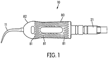
- Insert 10 provides a working tool 11 of conventional design, including a water conduit 12 therein for the passage of cooling water for use during scaling procedures, as is known to be advantageous in the art.
- Tool 11 is vibrated by conventional means such as by being connected to a magnetostrictive stack 20 through connecting body 21.
- Connecting body 21 has an internal fluid passageway 22 in fluid communication with tool 11 and tool fluid conduit 12, again in a substantially conventional manner.
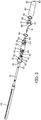
- Insert 10 may be inserted into a handpiece 23 ( FIG. 9 ) which provides appropriate connections to electrical power and pressurized fluid (not shown).
- Handpiece 23 is of conventional design and carries the components necessary to induce a magnetic field in stack 20 as is known in the art.
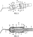
- insert 10 includes a nozzle 30 configured to surround portions of connecting body 21 and tool 11 in use.
- Nozzle 30 has a bore 30a therethrough which is configured to receive at least a portion of connecting body 21.
- a continuous fluid path is thus formed by the fluid communication between the source (not shown), the internal fluid passageway 22 and the conduit 12.
- nozzles were provided that were fabricated from two substantially mirror image halves that were placed around the connecting body and welded in place, resulting in areas of potential weakness and leakage as well as unsightly or damaging flash.
- the present invention alleviates this problem by providing nozzle 30 which does not require such welding, although welding or even adhesive bonding could be employed if desired and still be within the scope of the invention.
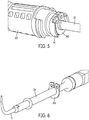
- nozzle 30 may be fabricated as a uni-body or one-piece construction, two-piece or any number of pieces, the nozzle 30 according to the present invention includes three main components, namely a retainer or retaining nozzle 31, a middle nozzle part 32 and a nozzle nose 33.
- Retainer nozzle 31 is configured to connect to middle nozzle 32 which in turn connects to nozzle nose 33, in any suitable manner.
- retaining nozzle 31 may have an end 40 proximal to said middle nozzle 32 when assembled proximal end 40 of retaining nozzle 31 may be provided with at least one tab 41 and at least one notch 42.
- Middle nozzle 32 likewise has an end 43 proximal to retaining nozzle 31 when assembled.
- Proximal end 43 of said middle nozzle 32 similarly has at least one tab 44 and at least one notch 45 in a complementary shape to tab 41 and notch 42 of proximal end 40 of said retaining nozzle 31.
- nozzle nose 33 preferably has an end 50 proximal to middle nozzle 32 when assembled, wherein proximal end 50 of nozzle nose 33 has at least one tab 51 and at least one notch 52.
- Middle nozzle 32 has an end 53 proximal to nozzle nose 33 when assembled, wherein proximal end 53 of middle nozzle 32 has at least one tab 54 and at least one notch 55 in a complementary shape to tab 51 and notch 52 of proximal end 50 of nozzle nose 33.
- Tab 51 of proximal end 50 of nozzle nose 33 is receivable within notch 55 of proximal end 53 of middle nozzle 32.
- Tab 54 of middle nozzle 32 is receivable within notch 52 of proximal end 50 of nozzle nose 33.
- the thus assembled connection is preferably secured in any conventional manner, and more preferably by use of a compression or hoopster ring 56.
- nozzle 30 is positioned upon or receives within connector body 21.
- a grip ring 60 is preferably employed.
- An example of a useful grip ring 60 is depicted in the drawings as a split ring that can be positioned upon connecting body 21 and either resiliently compress upon connecting body 21 or be compressed thereupon during assembly. By being a ring shape, grip ring 60 can thus receive connecting body 21 therein. Grip ring 60 may thereby use friction to hold position and prevent rotation of nozzle 30 once installed on connecting body 21.
- grip ring 60 secures ultrasonic dental insert 30 at a nodal location.
- a nodal location is a location along the ultrasonic insert that the vibrational standing wave has little to no amplitude.
- the nodal location includes a component that depends on friction between the metal (preferably stainless steel) connecting body 21 and the metal (again, preferably stainless steel) grip ring 60 to prevent axial movement and rotation.
- Grip ring 60 positions the other components of Insert 10 including nozzle 30, locating them such that the magnetostrictive stack 20 is accurately placed in the handpiece 23.
- Grip ring 60 clamps down on connecting body 21 such that it substantially is not moved without excesses forces (e.g. 10 lbs. axial and/or 3 lbs. torsional).
- Grip ring 60 may also provide asymmetrical features that help prevent other components of insert 10 to be engaged such that tool 11 will not rotate relative to a grip portion 60 to be described, or move axially. Grip ring 60 may be positioned at any desired location having the appropriate nodal function as above described. In the embodiment depicted in the drawings, grip ring 60 is positioned generally between middle nozzle 32 and retaining nozzle 31 when assembled. A cradle 61 may be provided ( FIG. 5 ) to accommodate and otherwise support grip ring 60.
- grip ring 60 is fixed to connector body 21 and is prevented by friction or otherwise from moving apart from undue pressure or excess force as described, physical interaction between grip ring 60 and cradle 61 will likewise prevent or substantially prevent movement of nozzle 30.
- the invention has been characterized and shown on the drawings as employing a split-ring style grip ring 60, it will be appreciated that any such device or construction positioned at the nodal location as herein described, is within the scope of the invention, including for example, a full ring, a block or the like (not shown).
- the nodal location placement of grip ring 60 may be determined by any conventional means.
- an insert 10 according to the invention as described was fabricated, upon which a finite element analysis was performed using SolidWorks Simulation software available from Solidworks Corp. of Waltham, MA.
- the type of dynamic analysis used was a Modal Time History Analysis, where a time curve with a harmonic load at the resonant driving frequency was applied to the end of stack 20. This varying load represented the forcing function produced by the magnetostrictive stack 20, made of permanickel material, when subjected to the magnetic field.
- FIG. 7 is a representation of the data thus obtained. Areas 70 and 71 represent such nodal locations. As shown, magnetostrictive stack 20 has a nodal location 70a, and areas of increasing vibration at areas 70b-70g. Similarly, connecting body 21 has a nodal location generally indicated by the number 71a and areas of increasing vibration at areas 71b-71d. Grip ring 60 would thereby be preferably indicated within area 71a. In this example, tool 11 was vibrated at a resonant frequency of about 29.6 kHz.
- an outer grip sleeve 80 is provided.
- grip sleeve 80 is fabricated as a uni-body or one piece of a formed material such as a silicone rubber or the like. Silicone rubber has been found to withstand repeated sterilization and cleaning procedures better that the heretofore common use of santoprene or the like.
- nozzle 30 forms a skeleton that supports grip sleeve 80 and helps give it form, and may be provided with internal molded-in structures such as ridges 80a to further conform to and be supported by nozzle 30.
- Grip sleeve 80 may also be provided with external texture of contours 81 to facilitate gripping and manipulation by a user. Further, grip sleeve 80 preferably has a bulbous end 82 to further facilitate gripping and manipulation.
- the improved grip sleeve 80 of the invention is has enhanced softness, feel, and shape compared to the current insert grip designs. The grip is robust and resilient to the conditions of extreme temperature and pressure typical to autoclave environments, and to washer/disinfectant chemicals. There is a trend in dentistry towards more comfortable, ergonomic equipment and instruments. A wider grip as grip sleeve 80 provides helps lessen hand fatigue to help maintain tactile sensitivity, as well as decrease the incidence of carpal tunnel syndrome. Grip sleeve 80 is provided with an aperture 83 through which tool 11 can be inserted when assembled.
- the dental inserts with the grip sleeve 80 as disclosed herein provides a dental insert 10 that helps prevent hand fatigue to maintain tactile sensitivity by providing a wide, comfortable grip.
- the unique grip shape described herein is designed to aid the hygienist in maintaining a proper relaxed grip while providing a convenient rest for their finger tip.
- the texture of the grip of the dental insert described herein is also a unique ripple pattern that is easy to clean, because it does not have deep crevices or pockets, can wick away fluids, and is subtle enough that it does not interfere with the clinician's tactile sensitivity.
- Grip 80 bulbous end 82 as described provides a finger rest preventing the index or middle finger, depending on fulcrum, from slipping off the insert 10. As a result the clinician or user can maintain a light grip and focus more on tip to tooth adaptation to improve both patient comfort and overall ergonomics.
- Other advantages include a one-piece grip according to the invention enable easier cleaning, a grip texture 81 that is specially designed to lessen the chance of slipping, a larger grip diameter may lessen muscle load and pinch force, the grip texture is designed to increase friction with fingers, thereby requiring less pinching force.
- Insert 10 may be provided with suitable O-rings 90 as is known in the art.
- nozzle 30 or indeed any component of insert 10 may be suitable configured to receive and support such devices.
- annular groove 91 may be provided in retaining nozzle 31 for this purpose.
- O-rings 90 made of a Viton material have been found to be advantageous. It will be appreciated that according to the invention, isolation of design elements as above described, separating mechanical assembly features and elements from seals, such that O-ring 90 seals assure a fluid tight assembly.
- a dental insert is provided that is an improvement over known Inserts in the art.
- a grip ring is used to secure the grip at a nodal area.
- Compression rings such as hoopster rings are used to secure plastic molded parts.
- a bulbous or knuckle design that provides for the interlocking of two halves while allowing both sealing and engagement with connecting body nodal area grip ring features is provided. Isolation of design elements, separating mechanical assembly features and elements from seals, such that O-ring seals assure a fluid tight assembly and plastic parts have been provided to support various joining technologies, such as flame brazing, induction brazing, and laser welding to join tips to connecting bodies.
- the grip, hoopster ring and nose nozzle can be removed in order to facilitate the replacement of the associated O-ring.
- the grip shape, grip retention and mechanical interlock with nozzle assembly, and the interior ribs 80a of the grip 80 allow steam to sterilize the interior of the grip while allowing venting to prevent movement or inflation of the silicone grip during steam autoclave cycle.
- the present Invention is an advantageous improvement over known dental inserts.
Claims (8)
- Insert (10) destiné à un ensemble détartreur dentaire à ultrasons comprenant :(a) un instrument de travail (11) ayant un passage d'un fluide à l'intérieur ;(b) un empilement magnétostrictif (20) ;(c) un corps de connecteur (21) reliant fonctionnellement ledit instrument (11) audit empilement magnétostrictif (20) ;(d) un ensemble de buse (30) ayant un alésage recevant un corps de connecteur (21) à l'intérieur ; et(e) un manche (60) recouvrant au moins une partie dudit ensemble de buse (30) ;ledit corps de connecteur (21) renfermant une voie de passage (22) à l'intérieur qui est en communication fluidique avec un passage de fluide de 1''instrument ;
ledit manche (80) étant une construction monobloc ayant une extrémité proximale et une extrémité distale en direction dudit instrument ; ladite extrémité proximale dudit manche étant munie d'une ouverture recevant un instrument et ladite extrémité distale étant pourvue d'une ouverture recevant un ensemble de buse (83), ledit ensemble de buse (30) comprend une buse de retenue (31), une buse intermédiaire (32) et un nez de buse (33). - Insert (10) selon la revendication 1, dans lequel ladite buse de retenue (31) est configurée pour recevoir au moins une partie dudit corps de connecteur (21), et pour se connecter avec ladite buse intermédiaire (32) d'une manière sensiblement étanche au fluide.
- Insert (10) selon la revendication 2, dans lequel ladite buse de retenue (31) a une extrémité (40) proximale en direction de ladite buse intermédiaire (32) lorsqu'elle est assemblée, ladite extrémité proximale (40) de ladite buse de retenue (31) ayant au moins une patte (41) et au moins une encoche (42) ; ladite buse intermédiaire (32) ayant une extrémité (43) proximale en direction de ladite buse de retenue (31) lorsqu'elle est assemblée, ladite extrémité proximale (43) de ladite buse intermédiaire (32) ayant au moins une patte (44) et au moins une encoche (45) de forme complémentaire à ladite au moins une patte (41) et au moins une encoche (42) de ladite extrémité proximale (40) de ladite buse de retenue (31) ; de sorte que ladite au moins une patte (41) de ladite extrémité proximale (40) de ladite buse de retenue (31) peut être reçue à l'intérieur de ladite au moins une encoche (45) de ladite extrémité proximale (43) de ladite buse intermédiaire (32), et ladite au moins une patte (44) de ladite buse intermédiaire (32) peut être reçue à l'intérieur de ladite au moins une encoche (42) de ladite extrémité proximale (40) de ladite buse de retenue (31).
- Insert (19) selon la revendication 2, dans lequel ledit nez de buse (33) comporte une extrémité (50) proximale en direction de ladite buse intermédiaire (32) lorsqu'elle est assemblée, ladite extrémité proximale dudit nez de buse (33) ayant au moins une patte (51) et au moins une encoche (52) ; ladite buse intermédiaire (32) ayant une extrémité (53) proximale en direction dudit nez de buse (33) lorsqu'elle est assemblée, ladite extrémité proximale de ladite buse intermédiaire (32) ayant au moins une patte (54) et au moins une encoche (55) de forme complémentaire à ladite au moins une patte (51) et au moins une encoche (52) de ladite extrémité proximale (50) dudit nez de buse (33) ;
de sorte que ladite au moins une patte (51) de ladite extrémité proximale (50) dudit nez de buse (33) peut être reçue à l'intérieur de ladite au moins une encoche (55) de ladite extrémité proximale (53) de ladite buse intermédiaire (32), et ladite au moins une patte (54) de ladite buse intermédiaire (32) peut être reçue à l'intérieur de ladite au moins une encoche (52) de ladite extrémité proximale (50) dudit nez de buse (33). - Insert (10) selon la revendication 1, dans lequel ledit manche (60) a une extrémité renflée (82) à proximité dudit instrument.
- Insert (10) selon la revendication 1, comprenant en outre une bague de retenue de manche (60) positionnée entre ladite buse intermédiaire (32) et ledit nez de buse (33).
- Insert (10) selon la revendication 6, dans lequel ladite bague de retenue de manche (60) est une bague fendue (60), de sorte que ledit corps de connecteur (21) peut être reçu à travers celle-ci.
- Insert selon la revendication 7, dans lequel ladite bague de retenue de manche (60) est positionnée à un emplacement nodal sur ledit corps de connecteur (21).
Applications Claiming Priority (2)
| Application Number | Priority Date | Filing Date | Title |
|---|---|---|---|
| US201361876853P | 2013-09-12 | 2013-09-12 | |
| PCT/US2014/055296 WO2015038844A1 (fr) | 2013-09-12 | 2014-09-12 | Insert de détartreur dentaire à ultrasons à préhension ergonomique |
Publications (2)
| Publication Number | Publication Date |
|---|---|
| EP3043739A1 EP3043739A1 (fr) | 2016-07-20 |
| EP3043739B1 true EP3043739B1 (fr) | 2018-03-28 |
Family
ID=52103151
Family Applications (1)
| Application Number | Title | Priority Date | Filing Date |
|---|---|---|---|
| EP14812823.4A Active EP3043739B1 (fr) | 2013-09-12 | 2014-09-12 | Insert de détartreur dentaire à ultrasons à préhension ergonomique |
Country Status (3)
| Country | Link |
|---|---|
| US (1) | US10368967B2 (fr) |
| EP (1) | EP3043739B1 (fr) |
| WO (1) | WO2015038844A1 (fr) |
Families Citing this family (4)
| Publication number | Priority date | Publication date | Assignee | Title |
|---|---|---|---|---|
| US11337892B2 (en) | 2015-11-12 | 2022-05-24 | Scalpal Llc | Grasping facilitators and uses thereof and kits involving the same |
| CN106725956A (zh) * | 2016-11-30 | 2017-05-31 | 桂林市啄木鸟医疗器械有限公司 | 一种超声洁牙机换能器及含其牙机手柄 |
| USD926016S1 (en) * | 2019-12-05 | 2021-07-27 | Mandi Jean-Marie Chisholm | Ergonomic grip |
| EP4132416A1 (fr) | 2020-04-10 | 2023-02-15 | Paschke Ultrasonix LLC | Instruments dentaires à ultrasons, ensembles inserts et inserts présentant une durabilité de performance améliorée |
Family Cites Families (62)
| Publication number | Priority date | Publication date | Assignee | Title |
|---|---|---|---|---|
| US3075288A (en) * | 1954-12-24 | 1963-01-29 | Cavitron Ultrasonics Inc | Dental instrument |
| US3924335A (en) * | 1971-02-26 | 1975-12-09 | Ultrasonic Systems | Ultrasonic dental and other instrument means and methods |
| US3809977A (en) * | 1971-02-26 | 1974-05-07 | Ultrasonic Systems | Ultrasonic kits and motor systems |
| US3919775A (en) * | 1971-12-30 | 1975-11-18 | Oscar Malmin | Endodontic sealing system and apparatus |
| US4169984A (en) * | 1976-11-30 | 1979-10-02 | Contract Systems Associates, Inc. | Ultrasonic probe |
| US4370131A (en) * | 1977-06-24 | 1983-01-25 | Surgical Design | Ultrasonic transducer tips |
| USRE30536E (en) | 1978-05-01 | 1981-03-03 | Cavitron Corporation | Ultrasonic device and method |
| US4315742A (en) * | 1979-11-05 | 1982-02-16 | Syntex (U.S.A.) Inc. | Vibratory device having tool assembly with fluid transport means |
| US4406284B1 (en) * | 1981-03-20 | 1997-11-18 | Surgical Design Corp | Ultrasonic handpiece design |
| US5419703A (en) * | 1988-02-18 | 1995-05-30 | Dentsply Research & Development Corp. | Method of subgingival scaling and lavage |
| US4961698A (en) * | 1989-06-16 | 1990-10-09 | Vlock D G | Ultrasonic device with additive chamber |
| FR2689385B1 (fr) * | 1992-04-06 | 1994-05-20 | Micro Mega Sa | Detartreur vibrant pour dentisterie. |
| FR2708193B1 (fr) * | 1993-06-29 | 1996-07-05 | Satelec Sa | Instrument chirurgical, destiné notamment à la chirurgie dentaire. |
| US5395240A (en) * | 1993-09-14 | 1995-03-07 | Dentsply Research & Development Corp. | Sterilizable dental medical handpiece containing electric coil |
| SE502270C2 (sv) * | 1994-01-28 | 1995-09-25 | Amdent Ab | Dental anordning med ett arbetsverktyg sammankopplat med en skyddshylsa |
| US5749727A (en) * | 1994-06-30 | 1998-05-12 | Dentsply Research & Development Corp. | Transducer activated subgingival tool tip |
| US5501596A (en) * | 1994-07-27 | 1996-03-26 | Young Dental Manufacturing Company, Inc. | Autoclavable dental scaler handpiece |
| JPH08189396A (ja) * | 1994-12-29 | 1996-07-23 | Honda Motor Co Ltd | 内燃エンジンの空燃比フィードバック制御装置 |
| US5772434A (en) * | 1995-11-28 | 1998-06-30 | Winston; Ronald H. | Ultrasonic tooth cleaner |
| US5775901A (en) * | 1996-03-07 | 1998-07-07 | Hu-Friedy Mfg. Co., Ltd. | Insert for ultrasonic scaler |
| US5927977A (en) * | 1996-11-27 | 1999-07-27 | Professional Dental Technologies, Inc. | Dental scaler |
| US6164968A (en) * | 1997-05-28 | 2000-12-26 | Feine; James | Trimodular ultrasonic dental device |
| US5975896A (en) * | 1997-11-28 | 1999-11-02 | Rainey; J. Tim | Non-rotary caries removal and restoration system |
| EP1182984B8 (fr) * | 1999-06-04 | 2010-12-15 | Dentsply International Inc. | Instrument de microchirurgie dentaire a ultrasons possedant une sortie d'eau et son procede de fabrication |
| US6494714B1 (en) * | 2000-01-24 | 2002-12-17 | Dentsply Research & Development Corp. | Method of making a tool tip and tool tip |
| US6716028B2 (en) * | 2000-08-04 | 2004-04-06 | Hu-Friedy Mfg. Co., Inc. | Ultrasonic swivel insert |
| AU2002326445A1 (en) * | 2001-08-01 | 2003-02-17 | Coltene/Whaledent, Inc. | Grip for ultrasonic scaler |
| JP3597158B2 (ja) * | 2001-09-21 | 2004-12-02 | 吉継 寺内 | 歯科用破折器具除去装置 |
| US8585404B2 (en) * | 2001-12-07 | 2013-11-19 | James S. Feine | Efficiency-modulated ultrasonic instrument inserts |
| US20050142515A1 (en) * | 2002-12-12 | 2005-06-30 | Hiam Levy | Dental tool having a hand grip |
| US7044736B2 (en) * | 2002-12-12 | 2006-05-16 | Discus Dental Impressions, Inc. | Ultrasonic dental insert having a hand grip fitted to a retaining ring |
| CA2414908A1 (fr) * | 2002-12-20 | 2004-06-20 | Derek Turner | Piece a main dentaire |
| US7150629B2 (en) * | 2003-03-19 | 2006-12-19 | James Feine | Lighted ultrasonic handpiece and color code grip system |
| JP3802885B2 (ja) * | 2003-06-10 | 2006-07-26 | 株式会社ナカニシ | 流体供給用コネクタ |
| WO2005002458A2 (fr) * | 2003-06-27 | 2005-01-13 | Discus Dental Impressions, Inc. | Instrument dentaire ultrasonique presentant une source lumineuse |
| US20050095556A1 (en) * | 2003-10-31 | 2005-05-05 | Pollock David P. | Ultrasonic insert with soft grip and method |
| US20050227201A1 (en) * | 2004-04-08 | 2005-10-13 | Pond Gary J | Irrigation tip adaptor for ultrasonic handpiece |
| US7766656B1 (en) * | 2004-08-27 | 2010-08-03 | Hu-Friedy Mfg. Co., Inc. | Dental delivery device |
| AU2005286985A1 (en) * | 2004-09-21 | 2006-03-30 | Discus Dental, Llc. | Dental instrument |
| US20060068361A1 (en) * | 2004-09-24 | 2006-03-30 | Dentalview, Inc. | Adapter for integrating an endoscope and ultrasonic scaler |
| US20090017414A1 (en) * | 2005-02-07 | 2009-01-15 | Amdent Ab | Dental Handpiece |
| US20060234185A1 (en) * | 2005-02-17 | 2006-10-19 | Discus Dental Impressions Inc. | Ultrasonic dental tool having a light source |
| US20080209650A1 (en) * | 2005-05-03 | 2008-09-04 | Ultreo, Inc. | Oral hygiene devices |
| US7959438B2 (en) * | 2005-08-11 | 2011-06-14 | James Feine | Movable pin ultrasonic transducer |
| US20070190486A1 (en) * | 2006-02-10 | 2007-08-16 | Deldent, Ltd | Dental instrument with light |
| US20090202961A1 (en) * | 2006-02-17 | 2009-08-13 | Discus Dental, Llc | Ultrasonic Dental Tool Having a Light Source |
| US20080318184A1 (en) * | 2007-06-13 | 2008-12-25 | Brian Zargari | Vibratory Dental Tool |
| US20090081605A1 (en) * | 2007-09-25 | 2009-03-26 | Ondine International, Ltd. | Photodynamic therapy device adapted for use with scaler |
| US20090111070A1 (en) * | 2007-10-31 | 2009-04-30 | Pollock David P | Ultrasonic insert with soft grip and method |
| US20090162810A1 (en) * | 2007-12-21 | 2009-06-25 | Peter Werner | Ultrasonic dental insert and lighted handpiece assembly |
| US20090208899A1 (en) * | 2008-02-20 | 2009-08-20 | Pond Gary J | Fluid bypass device for handheld dental devices |
| US8435034B2 (en) * | 2008-03-18 | 2013-05-07 | Zila, Inc. | Rotatable ultrasonic dental tool |
| US20100279250A1 (en) * | 2009-04-29 | 2010-11-04 | Inter-Med, Inc. | Programmable dental device |
| US9788925B2 (en) * | 2009-08-19 | 2017-10-17 | Vicky L Moran | Transducer activated tool with water conduit |
| ATE533427T1 (de) * | 2009-12-10 | 2011-12-15 | W & H Dentalwerk Buermoos Gmbh | Medizinische, insbesondere dentale, behandlungsvorrichtung zur abgabe eines mediums |
| WO2011077820A1 (fr) * | 2009-12-21 | 2011-06-30 | 有限会社錦部製作所 | Meule |
| US8080012B2 (en) * | 2010-03-17 | 2011-12-20 | Chun-Leon Chen | Ultrasonic sinus membrane/periosteum separation tool set |
| US9050161B2 (en) * | 2011-04-29 | 2015-06-09 | James S. Feine | Energy harvesting insert for an ultrasonic handpiece with electrical device |
| US10020679B2 (en) * | 2011-04-29 | 2018-07-10 | James Feine | Handheld electrical device system and method |
| US20120308956A1 (en) * | 2011-05-31 | 2012-12-06 | Devengencie James A | Multi-Piece Dental Ultrasonic Tip |
| JP6195077B2 (ja) * | 2012-05-31 | 2017-09-13 | 学校法人昭和大学 | 歯科用超音波洗浄装置 |
| US9820827B2 (en) * | 2012-06-13 | 2017-11-21 | James Feine | Ablation method and device |
-
2014
- 2014-09-12 WO PCT/US2014/055296 patent/WO2015038844A1/fr active Application Filing
- 2014-09-12 EP EP14812823.4A patent/EP3043739B1/fr active Active
- 2014-09-12 US US14/484,325 patent/US10368967B2/en active Active
Also Published As
| Publication number | Publication date |
|---|---|
| WO2015038844A1 (fr) | 2015-03-19 |
| EP3043739A1 (fr) | 2016-07-20 |
| US10368967B2 (en) | 2019-08-06 |
| US20150072304A1 (en) | 2015-03-12 |
Similar Documents
| Publication | Publication Date | Title |
|---|---|---|
| EP3043739B1 (fr) | Insert de détartreur dentaire à ultrasons à préhension ergonomique | |
| US7217128B2 (en) | Ultrasonic dental insert having interchangeable plastic and metal tips | |
| US6716028B2 (en) | Ultrasonic swivel insert | |
| US7104794B2 (en) | Ultrasonic dental tool having a light source | |
| EP2948096B1 (fr) | Ensemble pointe ultrasonore | |
| US6086369A (en) | Ultrasonic dental scaler insert | |
| JP5847847B2 (ja) | 口腔衛生装置用アタッチメント | |
| US5655906A (en) | Autoclavable dental sonic scaler | |
| DK2544620T3 (en) | Vibrating instrument | |
| US20080293009A1 (en) | Ultrasonic dental cleaner | |
| JP2001514923A (ja) | 医療用または歯科用器具およびこのような器具用のツール | |
| JP3465064B2 (ja) | 歯科用スケーラ− | |
| CN103565535B (zh) | 牙科压电超音波磁性切换洁牙机头及其控制方法 | |
| US7044736B2 (en) | Ultrasonic dental insert having a hand grip fitted to a retaining ring | |
| US9788925B2 (en) | Transducer activated tool with water conduit | |
| KR20180014110A (ko) | 치과용 치료기구 | |
| US20070190486A1 (en) | Dental instrument with light | |
| EP3525720B1 (fr) | Pièce à main dentaire à ultrasons à couplage rotatif | |
| JP2006326246A (ja) | 電動歯茎マッサ−ジ器 | |
| JP7279912B2 (ja) | 歯間のスペースメイキング装置およびスペースメイキング方法 | |
| CA2806841C (fr) | Outil active par transducteur muni d'une conduite d'eau | |
| JPS6085738A (ja) | 歯科手用器具用ホルダー |
Legal Events
| Date | Code | Title | Description |
|---|---|---|---|
| PUAI | Public reference made under article 153(3) epc to a published international application that has entered the european phase |
Free format text: ORIGINAL CODE: 0009012 |
|
| 17P | Request for examination filed |
Effective date: 20160404 |
|
| AK | Designated contracting states |
Kind code of ref document: A1 Designated state(s): AL AT BE BG CH CY CZ DE DK EE ES FI FR GB GR HR HU IE IS IT LI LT LU LV MC MK MT NL NO PL PT RO RS SE SI SK SM TR |
|
| AX | Request for extension of the european patent |
Extension state: BA ME |
|
| DAX | Request for extension of the european patent (deleted) | ||
| GRAP | Despatch of communication of intention to grant a patent |
Free format text: ORIGINAL CODE: EPIDOSNIGR1 |
|
| INTG | Intention to grant announced |
Effective date: 20171103 |
|
| RAP1 | Party data changed (applicant data changed or rights of an application transferred) |
Owner name: DENTSPLY SIRONA INC. |
|
| GRAS | Grant fee paid |
Free format text: ORIGINAL CODE: EPIDOSNIGR3 |
|
| GRAA | (expected) grant |
Free format text: ORIGINAL CODE: 0009210 |
|
| AK | Designated contracting states |
Kind code of ref document: B1 Designated state(s): AL AT BE BG CH CY CZ DE DK EE ES FI FR GB GR HR HU IE IS IT LI LT LU LV MC MK MT NL NO PL PT RO RS SE SI SK SM TR |
|
| REG | Reference to a national code |
Ref country code: GB Ref legal event code: FG4D |
|
| REG | Reference to a national code |
Ref country code: CH Ref legal event code: EP Ref country code: CH Ref legal event code: NV Representative=s name: E. BLUM AND CO. AG PATENT- UND MARKENANWAELTE , CH |
|
| REG | Reference to a national code |
Ref country code: SE Ref legal event code: TRGR |
|
| REG | Reference to a national code |
Ref country code: AT Ref legal event code: REF Ref document number: 982690 Country of ref document: AT Kind code of ref document: T Effective date: 20180415 |
|
| REG | Reference to a national code |
Ref country code: IE Ref legal event code: FG4D |
|
| REG | Reference to a national code |
Ref country code: DE Ref legal event code: R096 Ref document number: 602014023095 Country of ref document: DE |
|
| PG25 | Lapsed in a contracting state [announced via postgrant information from national office to epo] |
Ref country code: LT Free format text: LAPSE BECAUSE OF FAILURE TO SUBMIT A TRANSLATION OF THE DESCRIPTION OR TO PAY THE FEE WITHIN THE PRESCRIBED TIME-LIMIT Effective date: 20180328 Ref country code: HR Free format text: LAPSE BECAUSE OF FAILURE TO SUBMIT A TRANSLATION OF THE DESCRIPTION OR TO PAY THE FEE WITHIN THE PRESCRIBED TIME-LIMIT Effective date: 20180328 Ref country code: FI Free format text: LAPSE BECAUSE OF FAILURE TO SUBMIT A TRANSLATION OF THE DESCRIPTION OR TO PAY THE FEE WITHIN THE PRESCRIBED TIME-LIMIT Effective date: 20180328 Ref country code: NO Free format text: LAPSE BECAUSE OF FAILURE TO SUBMIT A TRANSLATION OF THE DESCRIPTION OR TO PAY THE FEE WITHIN THE PRESCRIBED TIME-LIMIT Effective date: 20180628 |
|
| REG | Reference to a national code |
Ref country code: NL Ref legal event code: MP Effective date: 20180328 |
|
| REG | Reference to a national code |
Ref country code: LT Ref legal event code: MG4D |
|
| REG | Reference to a national code |
Ref country code: FR Ref legal event code: PLFP Year of fee payment: 5 |
|
| PG25 | Lapsed in a contracting state [announced via postgrant information from national office to epo] |
Ref country code: RS Free format text: LAPSE BECAUSE OF FAILURE TO SUBMIT A TRANSLATION OF THE DESCRIPTION OR TO PAY THE FEE WITHIN THE PRESCRIBED TIME-LIMIT Effective date: 20180328 Ref country code: BG Free format text: LAPSE BECAUSE OF FAILURE TO SUBMIT A TRANSLATION OF THE DESCRIPTION OR TO PAY THE FEE WITHIN THE PRESCRIBED TIME-LIMIT Effective date: 20180628 Ref country code: GR Free format text: LAPSE BECAUSE OF FAILURE TO SUBMIT A TRANSLATION OF THE DESCRIPTION OR TO PAY THE FEE WITHIN THE PRESCRIBED TIME-LIMIT Effective date: 20180629 Ref country code: LV Free format text: LAPSE BECAUSE OF FAILURE TO SUBMIT A TRANSLATION OF THE DESCRIPTION OR TO PAY THE FEE WITHIN THE PRESCRIBED TIME-LIMIT Effective date: 20180328 |
|
| PG25 | Lapsed in a contracting state [announced via postgrant information from national office to epo] |
Ref country code: ES Free format text: LAPSE BECAUSE OF FAILURE TO SUBMIT A TRANSLATION OF THE DESCRIPTION OR TO PAY THE FEE WITHIN THE PRESCRIBED TIME-LIMIT Effective date: 20180328 Ref country code: AL Free format text: LAPSE BECAUSE OF FAILURE TO SUBMIT A TRANSLATION OF THE DESCRIPTION OR TO PAY THE FEE WITHIN THE PRESCRIBED TIME-LIMIT Effective date: 20180328 Ref country code: NL Free format text: LAPSE BECAUSE OF FAILURE TO SUBMIT A TRANSLATION OF THE DESCRIPTION OR TO PAY THE FEE WITHIN THE PRESCRIBED TIME-LIMIT Effective date: 20180328 Ref country code: PL Free format text: LAPSE BECAUSE OF FAILURE TO SUBMIT A TRANSLATION OF THE DESCRIPTION OR TO PAY THE FEE WITHIN THE PRESCRIBED TIME-LIMIT Effective date: 20180328 Ref country code: RO Free format text: LAPSE BECAUSE OF FAILURE TO SUBMIT A TRANSLATION OF THE DESCRIPTION OR TO PAY THE FEE WITHIN THE PRESCRIBED TIME-LIMIT Effective date: 20180328 Ref country code: EE Free format text: LAPSE BECAUSE OF FAILURE TO SUBMIT A TRANSLATION OF THE DESCRIPTION OR TO PAY THE FEE WITHIN THE PRESCRIBED TIME-LIMIT Effective date: 20180328 |
|
| PG25 | Lapsed in a contracting state [announced via postgrant information from national office to epo] |
Ref country code: SK Free format text: LAPSE BECAUSE OF FAILURE TO SUBMIT A TRANSLATION OF THE DESCRIPTION OR TO PAY THE FEE WITHIN THE PRESCRIBED TIME-LIMIT Effective date: 20180328 Ref country code: CZ Free format text: LAPSE BECAUSE OF FAILURE TO SUBMIT A TRANSLATION OF THE DESCRIPTION OR TO PAY THE FEE WITHIN THE PRESCRIBED TIME-LIMIT Effective date: 20180328 Ref country code: SM Free format text: LAPSE BECAUSE OF FAILURE TO SUBMIT A TRANSLATION OF THE DESCRIPTION OR TO PAY THE FEE WITHIN THE PRESCRIBED TIME-LIMIT Effective date: 20180328 |
|
| REG | Reference to a national code |
Ref country code: AT Ref legal event code: MK05 Ref document number: 982690 Country of ref document: AT Kind code of ref document: T Effective date: 20180328 |
|
| PG25 | Lapsed in a contracting state [announced via postgrant information from national office to epo] |
Ref country code: PT Free format text: LAPSE BECAUSE OF FAILURE TO SUBMIT A TRANSLATION OF THE DESCRIPTION OR TO PAY THE FEE WITHIN THE PRESCRIBED TIME-LIMIT Effective date: 20180730 |
|
| REG | Reference to a national code |
Ref country code: DE Ref legal event code: R097 Ref document number: 602014023095 Country of ref document: DE |
|
| PG25 | Lapsed in a contracting state [announced via postgrant information from national office to epo] |
Ref country code: AT Free format text: LAPSE BECAUSE OF FAILURE TO SUBMIT A TRANSLATION OF THE DESCRIPTION OR TO PAY THE FEE WITHIN THE PRESCRIBED TIME-LIMIT Effective date: 20180328 Ref country code: DK Free format text: LAPSE BECAUSE OF FAILURE TO SUBMIT A TRANSLATION OF THE DESCRIPTION OR TO PAY THE FEE WITHIN THE PRESCRIBED TIME-LIMIT Effective date: 20180328 |
|
| PLBE | No opposition filed within time limit |
Free format text: ORIGINAL CODE: 0009261 |
|
| STAA | Information on the status of an ep patent application or granted ep patent |
Free format text: STATUS: NO OPPOSITION FILED WITHIN TIME LIMIT |
|
| 26N | No opposition filed |
Effective date: 20190103 |
|
| PG25 | Lapsed in a contracting state [announced via postgrant information from national office to epo] |
Ref country code: MC Free format text: LAPSE BECAUSE OF FAILURE TO SUBMIT A TRANSLATION OF THE DESCRIPTION OR TO PAY THE FEE WITHIN THE PRESCRIBED TIME-LIMIT Effective date: 20180328 |
|
| PG25 | Lapsed in a contracting state [announced via postgrant information from national office to epo] |
Ref country code: SI Free format text: LAPSE BECAUSE OF FAILURE TO SUBMIT A TRANSLATION OF THE DESCRIPTION OR TO PAY THE FEE WITHIN THE PRESCRIBED TIME-LIMIT Effective date: 20180328 |
|
| REG | Reference to a national code |
Ref country code: BE Ref legal event code: MM Effective date: 20180930 |
|
| REG | Reference to a national code |
Ref country code: IE Ref legal event code: MM4A |
|
| PG25 | Lapsed in a contracting state [announced via postgrant information from national office to epo] |
Ref country code: LU Free format text: LAPSE BECAUSE OF NON-PAYMENT OF DUE FEES Effective date: 20180912 |
|
| PG25 | Lapsed in a contracting state [announced via postgrant information from national office to epo] |
Ref country code: IE Free format text: LAPSE BECAUSE OF NON-PAYMENT OF DUE FEES Effective date: 20180912 |
|
| PG25 | Lapsed in a contracting state [announced via postgrant information from national office to epo] |
Ref country code: BE Free format text: LAPSE BECAUSE OF NON-PAYMENT OF DUE FEES Effective date: 20180930 |
|
| PG25 | Lapsed in a contracting state [announced via postgrant information from national office to epo] |
Ref country code: MT Free format text: LAPSE BECAUSE OF NON-PAYMENT OF DUE FEES Effective date: 20180912 |
|
| PG25 | Lapsed in a contracting state [announced via postgrant information from national office to epo] |
Ref country code: TR Free format text: LAPSE BECAUSE OF FAILURE TO SUBMIT A TRANSLATION OF THE DESCRIPTION OR TO PAY THE FEE WITHIN THE PRESCRIBED TIME-LIMIT Effective date: 20180328 |
|
| PG25 | Lapsed in a contracting state [announced via postgrant information from national office to epo] |
Ref country code: CY Free format text: LAPSE BECAUSE OF FAILURE TO SUBMIT A TRANSLATION OF THE DESCRIPTION OR TO PAY THE FEE WITHIN THE PRESCRIBED TIME-LIMIT Effective date: 20180328 Ref country code: HU Free format text: LAPSE BECAUSE OF FAILURE TO SUBMIT A TRANSLATION OF THE DESCRIPTION OR TO PAY THE FEE WITHIN THE PRESCRIBED TIME-LIMIT; INVALID AB INITIO Effective date: 20140912 Ref country code: MK Free format text: LAPSE BECAUSE OF NON-PAYMENT OF DUE FEES Effective date: 20180328 |
|
| PG25 | Lapsed in a contracting state [announced via postgrant information from national office to epo] |
Ref country code: IS Free format text: LAPSE BECAUSE OF FAILURE TO SUBMIT A TRANSLATION OF THE DESCRIPTION OR TO PAY THE FEE WITHIN THE PRESCRIBED TIME-LIMIT Effective date: 20180728 |
|
| PGFP | Annual fee paid to national office [announced via postgrant information from national office to epo] |
Ref country code: IT Payment date: 20230810 Year of fee payment: 10 Ref country code: GB Payment date: 20230803 Year of fee payment: 10 |
|
| PGFP | Annual fee paid to national office [announced via postgrant information from national office to epo] |
Ref country code: SE Payment date: 20230810 Year of fee payment: 10 Ref country code: FR Payment date: 20230808 Year of fee payment: 10 Ref country code: DE Payment date: 20230802 Year of fee payment: 10 |
|
| PGFP | Annual fee paid to national office [announced via postgrant information from national office to epo] |
Ref country code: CH Payment date: 20231001 Year of fee payment: 10 |