EP3525720B1 - Pièce à main dentaire à ultrasons à couplage rotatif - Google Patents
Pièce à main dentaire à ultrasons à couplage rotatif Download PDFInfo
- Publication number
- EP3525720B1 EP3525720B1 EP17793769.5A EP17793769A EP3525720B1 EP 3525720 B1 EP3525720 B1 EP 3525720B1 EP 17793769 A EP17793769 A EP 17793769A EP 3525720 B1 EP3525720 B1 EP 3525720B1
- Authority
- EP
- European Patent Office
- Prior art keywords
- handpiece
- assembly
- cable assembly
- primary
- transducer
- Prior art date
- Legal status (The legal status is an assumption and is not a legal conclusion. Google has not performed a legal analysis and makes no representation as to the accuracy of the status listed.)
- Active
Links
- 230000008878 coupling Effects 0.000 title claims description 23
- 238000010168 coupling process Methods 0.000 title claims description 23
- 238000005859 coupling reaction Methods 0.000 title claims description 23
- 239000012530 fluid Substances 0.000 claims description 31
- 230000007246 mechanism Effects 0.000 claims description 12
- 238000000034 method Methods 0.000 claims description 6
- 230000004907 flux Effects 0.000 claims description 4
- 229910000859 α-Fe Inorganic materials 0.000 claims description 4
- 238000004891 communication Methods 0.000 claims description 3
- 238000002560 therapeutic procedure Methods 0.000 claims 2
- 239000004809 Teflon Substances 0.000 description 7
- 229920006362 Teflon® Polymers 0.000 description 7
- 238000012546 transfer Methods 0.000 description 5
- XLYOFNOQVPJJNP-UHFFFAOYSA-N water Substances O XLYOFNOQVPJJNP-UHFFFAOYSA-N 0.000 description 5
- 238000001816 cooling Methods 0.000 description 4
- 239000012141 concentrate Substances 0.000 description 3
- 238000010276 construction Methods 0.000 description 3
- 239000002783 friction material Substances 0.000 description 3
- 238000004804 winding Methods 0.000 description 3
- 238000013461 design Methods 0.000 description 2
- 230000005284 excitation Effects 0.000 description 2
- 239000000463 material Substances 0.000 description 2
- 239000002184 metal Substances 0.000 description 2
- GHXZTYHSJHQHIJ-UHFFFAOYSA-N Chlorhexidine Chemical compound C=1C=C(Cl)C=CC=1NC(N)=NC(N)=NCCCCCCN=C(N)N=C(N)NC1=CC=C(Cl)C=C1 GHXZTYHSJHQHIJ-UHFFFAOYSA-N 0.000 description 1
- 230000009471 action Effects 0.000 description 1
- 230000006978 adaptation Effects 0.000 description 1
- 210000003484 anatomy Anatomy 0.000 description 1
- 230000001580 bacterial effect Effects 0.000 description 1
- 230000004888 barrier function Effects 0.000 description 1
- 230000005540 biological transmission Effects 0.000 description 1
- 229960003260 chlorhexidine Drugs 0.000 description 1
- 238000004140 cleaning Methods 0.000 description 1
- 238000011109 contamination Methods 0.000 description 1
- 238000001804 debridement Methods 0.000 description 1
- 208000002925 dental caries Diseases 0.000 description 1
- 230000001419 dependent effect Effects 0.000 description 1
- 238000010292 electrical insulation Methods 0.000 description 1
- 238000005516 engineering process Methods 0.000 description 1
- 210000003746 feather Anatomy 0.000 description 1
- 239000011521 glass Substances 0.000 description 1
- 238000005286 illumination Methods 0.000 description 1
- 230000010354 integration Effects 0.000 description 1
- 238000012544 monitoring process Methods 0.000 description 1
- 210000000214 mouth Anatomy 0.000 description 1
- 239000002324 mouth wash Substances 0.000 description 1
- 229940051866 mouthwash Drugs 0.000 description 1
- 208000028169 periodontal disease Diseases 0.000 description 1
- 230000003239 periodontal effect Effects 0.000 description 1
- 239000004014 plasticizer Substances 0.000 description 1
- 229920001296 polysiloxane Polymers 0.000 description 1
- 230000001681 protective effect Effects 0.000 description 1
- 230000004044 response Effects 0.000 description 1
- 230000003938 response to stress Effects 0.000 description 1
- 238000007789 sealing Methods 0.000 description 1
- 229910000679 solder Inorganic materials 0.000 description 1
- 230000003068 static effect Effects 0.000 description 1
- 230000001954 sterilising effect Effects 0.000 description 1
- 238000004659 sterilization and disinfection Methods 0.000 description 1
- 230000008961 swelling Effects 0.000 description 1
- 230000002194 synthesizing effect Effects 0.000 description 1
- 238000004506 ultrasonic cleaning Methods 0.000 description 1
- 238000013022 venting Methods 0.000 description 1
Images


Classifications
-
- A—HUMAN NECESSITIES
- A61—MEDICAL OR VETERINARY SCIENCE; HYGIENE
- A61C—DENTISTRY; APPARATUS OR METHODS FOR ORAL OR DENTAL HYGIENE
- A61C1/00—Dental machines for boring or cutting ; General features of dental machines or apparatus, e.g. hand-piece design
- A61C1/02—Dental machines for boring or cutting ; General features of dental machines or apparatus, e.g. hand-piece design characterised by the drive of the dental tools
- A61C1/07—Dental machines for boring or cutting ; General features of dental machines or apparatus, e.g. hand-piece design characterised by the drive of the dental tools with vibratory drive, e.g. ultrasonic
-
- A—HUMAN NECESSITIES
- A61—MEDICAL OR VETERINARY SCIENCE; HYGIENE
- A61C—DENTISTRY; APPARATUS OR METHODS FOR ORAL OR DENTAL HYGIENE
- A61C1/00—Dental machines for boring or cutting ; General features of dental machines or apparatus, e.g. hand-piece design
- A61C1/08—Machine parts specially adapted for dentistry
- A61C1/18—Flexible shafts; Clutches or the like; Bearings or lubricating arrangements; Drives or transmissions
- A61C1/188—Means for allowing non driven rotation of the tool relative to the handle, e.g. toolswivel
-
- A—HUMAN NECESSITIES
- A61—MEDICAL OR VETERINARY SCIENCE; HYGIENE
- A61C—DENTISTRY; APPARATUS OR METHODS FOR ORAL OR DENTAL HYGIENE
- A61C17/00—Devices for cleaning, polishing, rinsing or drying teeth, teeth cavities or prostheses; Saliva removers; Dental appliances for receiving spittle
- A61C17/16—Power-driven cleaning or polishing devices
- A61C17/20—Power-driven cleaning or polishing devices using ultrasonics
-
- A—HUMAN NECESSITIES
- A61—MEDICAL OR VETERINARY SCIENCE; HYGIENE
- A61C—DENTISTRY; APPARATUS OR METHODS FOR ORAL OR DENTAL HYGIENE
- A61C17/00—Devices for cleaning, polishing, rinsing or drying teeth, teeth cavities or prostheses; Saliva removers; Dental appliances for receiving spittle
- A61C17/02—Rinsing or air-blowing devices, e.g. using fluid jets or comprising liquid medication
- A61C17/0202—Hand-pieces
Definitions
- the present invention relates generally to dental handpieces and more specifically to an ultrasonic dental handpiece assembly with rotary coupling and a fluid transmission mechanism for providing the handpiece assembly with energy and cooling lavage.
- An ultrasonic dental tool typically includes a handpiece connected to a cable that connects both electrical power, ground, and feedback circuits.
- the cable may include a flexible tube to provide lavage (e.g., water, Chlorohexidine, mouth wash).
- lavage e.g., water, Chlorohexidine, mouth wash.
- WO 2009/117464 A1 discloses an ultrasonic dental insert.
- US 2003/022129 A1 discloses an ultrasonic insert insertable into a handpiece.
- US 2002/127512 A1 discloses an adapter for use with an ultrasonic unit.
- a dental handpiece, a dental system including a dental handpiece and a method of using said dental handpiece that shows one or more improvements in comparison with prior art is desired in the art.
- the system comprises a dental handpiece, dental handpiece tip and a cable assembly wherein the handpiece incorporates a dynamic fluid interface and a swivel mechanism that allows the handpiece and handpiece tip to rotate freely relative to a handpiece cable or user's hand while unrestrictedly transmitting energy and lavage inside the handpiece through the decoupling of the handpiece from a torsion load applied to it by the handpiece cable and internal tubing and wires.
- the handpiece houses a piezo stack and a secondary coil
- the cable assembly comprises a cable (cable sheath, tubing, and wires) and a primary coil, the cable providing a supply of electrical energy and cooling lavage to the handpiece.
- the primary and secondary coils form a transformer with the secondary coil inductively coupled to the primary coil and with the secondary coil in electrical communication with said piezo stack.
- An object is to provide an ultrasonic dental handpiece system with rotary coupling wherein the system comprises a dental handpiece and a dental handpiece tip, said system incorporating a swivel mechanism and a rotary fluid coupling to allow the handpiece and tip to rotate, preferably 360 degrees, relative to a handpiece cable thereby decoupling the handpiece from a torsion load applied to it by the cable and internal fluid tubing and electrical wires.
- Another object is to provide an ultrasonic dental handpiece system with rotary coupling that may be used for general supra and subgingival scaling applications, endodontic procedures and for periodontal debridement for all types of periodontal diseases.
- Another object is to provide an ultrasonic dental handpiece with rotary coupling that replaces conventional electrical connections by the use of a transformer, hereinafter referred to as a rotary transformer, to transfer ultrasonic power via electromagnetic coupling between a primary coil and a secondary coil.
- a transformer hereinafter referred to as a rotary transformer
- Two concentric shells nest inside each other protecting the coils from fluid ingress and contamination while creating an electromagnetic coupling used to drive the piezo handpiece.
- latching mechanisms to provide a means for making the handpiece easily detachable for sterilization and replacement, and to offer the capability of venting during autoclave cycles in addition to insensitivity to fluid ingress.
- the coil over coil design eliminates the need for commutating electrical contacts and hermetic radial seals that provide low friction slip coupling barrier to fluid and steam.
- the figures illustrate a handpiece to which a piezo assembly and secondary coil are mechanically attached and housed and a cable assembly comprising a primary coil and handpiece cable wherein the handpiece cable provides a supply of electrical energy and cooling lavage.
- the primary and secondary coils form a transformer wherein the secondary coil is inductively coupled to the primary coil with the secondary coil in electrical communication with said piezo assembly.
- a ferrite core underneath the primary winding concentrates the flux to increase coupling with the secondary winding to allow for the efficient transfer of power.
- Each coil is sealed in its own shell to eliminate the risk for fluid entry that degrades electrical insulation between the user and the high voltage electrical connection.
- an electrical circuit capable of characterizing the piezoelectric transducer over a multitude of operating frequencies through digitally controlled drive electronics.
- the drive circuitry is capable of digitally synthesizing a range of excitation frequencies while simultaneously monitoring drive voltage and current.
- the drive voltage and current are digitized via an analog to digital converter to provide a microcontroller with information such as phase relationship, impedance, admittance, and current draw. This information coupled with the excitation frequency is analyzed to determine the transducer's optimum operation frequency which will be at or near the resonant frequency of the transducer and attached tool.
- the drive voltage and current are dynamically controlled using pulse width modulation techniques based on user settings. Preferably the drive voltage and current approximate a sine wave in order to minimize unwanted harmonics that result in audible noise and transformer losses generating heat in the handpiece and potentially unwanted electromagnetic emissions.
- a piezo scaler handpiece 14 is uncoupled from cable assembly 16.
- the cable assembly is supplied with lavage and electrical energy through the handpiece cable 15.
- a scaler tip (not shown) is also able to rotate freely relative to the handpiece body through the adoption of O-rings 2 in the design of the handpiece housing tip 1 as shown in Fig. 4 .
- the coupling arrangement allows the provision of power to a piezoelectric pile 8 coupled to a mechanical working end (not shown).
- the coupling also allows the provision of lavage through the body of the handpiece 14 to the mechanical working end (not shown) of the piezoelectric pile 8.
- the ability to uncouple the handpiece 14 from the primary coil coupling 40 allows mechanical and electrical integration of the components of the handpiece 14 such that it can be easily cleaned, and can resist fluid ingress and withstand high temperatures and pressures from autoclaving without any damage to internal components. This also allows a handpiece of size comparable to conventional dental handpieces to be created.
- the primary coil coupling 40 of the cable assembly 16 is a friction grip coupling.
- a Teflon bearing 19, in Fig. 2 resides in the in rear end of the handpiece.
- An O-ring 20 interlocks with the inside diameter of the Teflon bearing to secure the handpiece to the cable assembly.
- a primary coil protruding from the end of the cable assembly is delivered into the core of a secondary coil located in the handpiece.
- the turns ratio will normally be 1:1.
- Fig. 2 which illustrates a cross sectional view of the rotational interface (cable assembly/ handpiece connection)
- the Teflon bearing 19 resides in the proximal end of the handpiece.
- An O-ring 20 of the cable assembly interlocks with the inside diameter of the Teflon bearing 19 to secure the handpiece to the cable assembly.
- a fluid channel of the handpiece cable 15 is connected to a fluid channel of a primary bobbin 31 through a primary washer 34.
- Lavage is directed through the fluid channels to the piezo assembly 23 to cool the ultrasonic scaling tip.
- the cable 15 also supplies electrical energy, preferably through electrically insulated wires (not shown).
- an interference fit between the dynamic fluid interface 17 and primary bobbin 31 of the primary coil 27 generates a force that results in frictional torque and consumes energy as the handpiece is rotated by the clinician.
- the correct functioning of the interface depends on maintaining a sealing force between the primary bobbin 31 and inside diameter of the dynamic fluid interface 17.
- an appropriate load usually less than 7.06mN.m (1 in-oz), and preferably less than 3.53 mN.m (1 ⁇ 2 in-oz) is maintained to prevent seal leakage and to guarantee a smoothly and freely rotatable handpiece that provides maximum control to achieve proper scaler tip orientation and adaptation to dental anatomy.
- This minimal torque will allow the clinician to rotate the insert with one hand, eliminating the need to leave the oral cavity to use both hands in order to reposition the tip.
- the amount of torque can be read directly from a torque watch as the handpiece is rotated relative to the cable.
- the o-rings' 49 ability to seal against the head pressure of an ultrasonic handpiece can be directly estimated by the peak contact stress of the o-ring.
- the radial load on the primary bobbin 31 will be negligible at the o-ring 49 because of the bearing, the feather like touch used during scaling, and the fact that the o-ring seal is located deep in the handpiece.
- the primary wall peak contact stress response for radial loading is the greatest as a result of o-ring deformation.
- the o-ring stiffness, material, and shaft finish affects both the static and dynamic coefficient of friction. Care is taken such that the primary bobbin shaft surface finish is glass like and that any parting line flash is eliminated. O-ring stiffness and percent deformation directly controls radial load.
- high temperature o-ring materials such as Teflon, Teflon coated fluorocarbons, and high temperature silicone, are used to prevent swelling from moisture ingress or stiffening from a loss of plasticizers from the o-ring after repeated autoclave cycles.
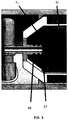
- Fig. 13 shows an alternative embodiment of the dynamic fluid interface. This features low friction materials, smooth finish and a small radius giving the interface resilience to damage when the two halves are separated.
- Bobbin 44 moves with the cable and water fitting 45 moves with the handpiece. 46 shows the direction of lavage flow.
- Fig. 4 illustrates the general components of a piezo ultrasonic scaling handpiece with a transducer.
- the handpiece comprises a housing tip 1 and a housing 3.
- the housing 3 is connected to the housing tip 1 by the use of a housing tip O-ring 2.
- a connector O-ring 4 connects the housing to a connector 5 from which power is supplied to the transducer.
- the transducer is housed in the handpiece and comprises an ultrasonic horn 6 , piezoelectric elements 8 , solder tabs 7 that transfer electrical voltage to the surface of the piezo element, and a Tail Mass (or back mass) 9 with an o-ring 10 that when assembled forms a Langevin or metal sandwich transducer.
- a metal barb fluid fitting 11 provides a connection to deliver cooling lavage through the center of the transducer in order to cool the ultrasonic scaling tip.
- Fig. 5 illustrates an exploded view of the handpiece with the transducer 23 and secondary coil in place 24.
- the outer casework 22 consists of two shells fastened together by screws. A single shell or alternative bonding technique may be implemented to improve ease of cleaning and aesthetics.
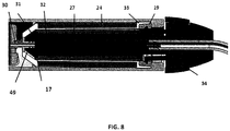
- FIGs 6 , 7 , 8 and 9 illustrate an alternative embodiment of the invention.
- a cable assembly 16 is provided with a clip mechanism to allow affixing of the cable assembly to the handpiece.
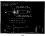
- FIG. 7 an exploded side view of the cable assembly of the embodiment is shown.
- the figure shows a clip release version of the cable assembly having a primary coil construction.
- the primary coil 27 is wound on the primary bobbin 31 and covered with a protective outer casing 26 to protect the coils from fluid ingress and damage.
- a clip mechanism 28, housed in a clip casing 29 , and through which the handpiece cable 15 passes is connected to the primary bobbin 31 through a primary washer 34 as shown in Fig. 8 .
- a ferrite core 32 concentrates the flux to increase coupling to allow for the efficient transfer of power.
- a cross sectional view of the alternative embodiment of Fig. 6 illustrates the location of the piezo assembly 23 in relation to primary coil 27 and secondary coil 24.
- the mechanical working end of the piezo scaling tip (not shown) extends from the distal end 18 of the piezo assembly 23.
- an alternative embodiment of the invention comprises components that rotate with the piezo 36 which are mechanically or electrically connected to the cable.
- a rotary transformer is housed within the handpiece.
- a transducer 23 is fixed to the nose 43 at the distal 41 end of the handpiece such that the nose 43 , transducer 23 , inner housing 47 and primary coil 27 are movable components 36 and can rotate relative to the secondary coil 24 and outer housing 48 which are stationary components 35 of the handpiece. This allows the handpiece tip(not shown) to be oriented to the tooth(not shown) while rotating the nose 43 , rotating fluid seal 37 located at the proximal end 42 , and other rotating components 36 relative to the stationary components 35.
- the operation of a preferred embodiment of the handpiece involves providing the piezoelectric elements 8 with energy that causes the elements to flex. This movement results in vibrations in the mechanical working end of the piezo scaling tip(not shown) which is then applied on to the teeth. High vibrational energy created by the mechanical action of the tip crushes and removes calculus. Shockwaves and turbulence created disrupt bacterial cells and biofilms.
- the piezo transducer assembly 23 is electrically connected by wires 12 , 13 to a secondary winding 24.
- a water tube (not shown) connects the fluid transferred from the primary bobbin 31 through the dynamic fluid interface 17 and into a water fitting 30 at the end of the secondary bobbin 33.
- the water tube then connects with a barb fitting 11 at the proximal end of the transducer assembly 23 located at the tail mass 9.
- the secondary coil 24 works in conjunction with the primary coil 27 to couple ultrasonic power.
- the primary coil 27 induces a voltage and current on the secondary coil that is used to energize the piezoelectric transducer.
- the secondary coil 24 and transducer are mechanically fixed in the same housing, such that the wires and tubing between the secondary coil and transducer only experience ambient ultrasonic vibration.
- the primary coil and dynamic fluid interface 17 are meant to slip inside the handpiece with very little frictional drag so that the operator can manipulate the ultrasonic tip without any torsional resistance from the handpiece cable 15 or the internal seals and bearings.
- the dynamic fluid interface 17 allows for the rotation of the primary coil relative to the secondary coil without seal leakage due to the use of the rotary coupling means.
- the rotary coupling features low friction materials, smooth finish and a small radius to reduce the frictional torque generated from the force of the interference fit.
- the secondary coil 24 may provide a power supply to electrical devices such as, but not limited to high speed rotary machines, low speed rotary machines, curing lights and caries detectors.
- a circuit to rectify the ultrasonic drive signal to provide DC power to energize a secondary circuit may be achieved.
- a tertiary coil may also be included with the secondary coil to provide a low voltage power source to energize integrated LED illumination common to piezoelectric scaling handpieces.
Claims (12)
- Pièce à main dentaire (14) comprenant :une pointe de pièce à main ;un logement de pièce à main (3) renfermant un ensemble transducteur (23) et une bobine secondaire (24) ;un ensemble de câble (16) comprenant un câble de pièce à main (15) et une bobine principale (27) ledit ensemble de câble (16) étant raccordé audit logement de pièce à main (3) ;une interface de fluide dynamique (17) ; etun mécanisme pivotant ;dans lequel l'interface de fluide dynamique (17) et le mécanisme pivotant sont configurés pour permettre à la pièce à main (14) et à la pointe de pièce à main de tourner librement par rapport à l'ensemble de câble (16) ou à la main d'un utilisateur tout en transmettant sans restriction de l'énergie et un lavage à l'intérieur de la pièce à main (14), etdans lequel la pièce à main (14) est découplée d'une charge torsionnelle qui lui est appliquée par l'ensemble de câble (16) et les tubulure et fils internes.
- Pièce à main dentaire (14) selon la revendication 1, dans laquelle l'ensemble transducteur (23) est un ensemble piézo-électrique (23).
- Pièce à main dentaire (14) selon la revendication 1, dans laquelle l'ensemble de câble (16) est configuré pour fournir un lavage et de l'énergie électrique à la pièce à main.
- Pièce à main dentaire (14) selon la revendication 1, dans laquelle les bobines principales (27) et secondaires (24) forment un transformateur rotatif, dans lequel la bobine secondaire (24) est couplée de manière inductive à la bobine principale (27) avec la bobine secondaire (24) en communication électrique avec l'ensemble du transducteur (23).
- Pièce à main dentaire (14) selon la revendication 4, comprenant en outre un noyau de ferrite (32) pour la concentration du flux afin d'augmenter le couplage de la bobine principale (27) avec la bobine secondaire (24) .
- Pièce à main dentaire (14) selon la revendication 4, dans laquelle le rapport de rotation est de 1:1.
- Pièce à main dentaire (14) selon la revendication 1, dans laquelle l'ensemble de câble (16) est détachable du logement de pièce à main (3).
- Pièce à main dentaire (14) selon la revendication 1, dans laquelle la pièce à main (14) est configurée pour être autoclavable.
- Pièce à main dentaire (14) selon la revendication 1, comprenant en outre une interface de fluide dynamique (17) et un bobinage principal (31) de ladite bobine principale (27), dans laquelle un couple de friction généré à partir d'une force d'un ajustement d'interférence entre l'interface de fluide dynamique (17) et le bobinage principal (31) est maintenu à moins de 7,06mN.m (1 en once).
- Pièce à main dentaire (14) selon la revendication 9, dans laquelle le couple est inférieur à 3,53 mN.m (½ en once).
- Procédé non thérapeutique pour l'utilisation d'une pièce à main dentaire (14), dans lequel la pièce à main dentaire est définie selon l'une quelconque des revendications 1 à 10, le procédé comprenant :la fourniture d'énergie électrique à des bobines principales (27) d'un ensemble de câble (16) ;le couplage de ladite énergie électrique à des bobines secondaires (24) dans un logement de pièce à main (3) ;la fourniture d'un ensemble transducteur (23) avec de l'énergie électrique à partir desdites bobines secondaires (24) pour provoquer des vibrations à l'extrémité de travail d'une pointe de la pièce à main (14) ;la rotation de la pièce à main (14) par rapport à l'ensemble de câble (16) de sorte que l'ensemble de transducteur (23), la bobine secondaire (24) et le logement de pièce à main (3) tournent comme un seul ensemble ;dans lequel une interface de fluide dynamique (17) dudit ensemble de câble (16) et les bobines principales (27) glissent à l'intérieur du logement de pièce à main (3) avec peu de résistance de frottement pour découpler ladite pointe de l'ensemble de câble (16) et des joints et roulements internes de la pièce à main (14).
- Procédé non thérapeutique selon la revendication 11, dans lequel l'ensemble transducteur (23) est un ensemble piézo-électrique (23).
Applications Claiming Priority (2)
| Application Number | Priority Date | Filing Date | Title |
|---|---|---|---|
| US201662409120P | 2016-10-17 | 2016-10-17 | |
| PCT/US2017/056841 WO2018075424A1 (fr) | 2016-10-17 | 2017-10-17 | Pièce à main dentaire à ultrasons à couplage rotatif |
Publications (2)
| Publication Number | Publication Date |
|---|---|
| EP3525720A1 EP3525720A1 (fr) | 2019-08-21 |
| EP3525720B1 true EP3525720B1 (fr) | 2020-11-25 |
Family
ID=60202445
Family Applications (1)
| Application Number | Title | Priority Date | Filing Date |
|---|---|---|---|
| EP17793769.5A Active EP3525720B1 (fr) | 2016-10-17 | 2017-10-17 | Pièce à main dentaire à ultrasons à couplage rotatif |
Country Status (5)
| Country | Link |
|---|---|
| US (1) | US10575924B2 (fr) |
| EP (1) | EP3525720B1 (fr) |
| JP (1) | JP7231538B2 (fr) |
| CA (1) | CA3040690A1 (fr) |
| WO (1) | WO2018075424A1 (fr) |
Families Citing this family (1)
| Publication number | Priority date | Publication date | Assignee | Title |
|---|---|---|---|---|
| CN114224525A (zh) * | 2022-01-06 | 2022-03-25 | 天津大学 | 一种牙科弯手机外部超声复合振动附件式手柄 |
Family Cites Families (9)
| Publication number | Priority date | Publication date | Assignee | Title |
|---|---|---|---|---|
| US20020127512A1 (en) | 2001-02-22 | 2002-09-12 | Shu Chen | Ultrasonic unit with rear swivel |
| US6811399B2 (en) * | 2001-07-27 | 2004-11-02 | Hu-Friedy Mfg. Co., Inc. | Torque lock for ultrasonic swivelable inserts and method |
| JP2003124035A (ja) * | 2001-10-15 | 2003-04-25 | Daido Steel Co Ltd | コア材 |
| DE102006051510A1 (de) * | 2006-03-09 | 2007-09-13 | Kaltenbach & Voigt Gmbh | Zahnärztliches, zahnmedizinisches oder dentaltechnisches Handstück mit Elektromotor |
| MX2010010036A (es) * | 2008-03-18 | 2010-12-20 | Discus Dental Llc | Herramienta dental ultrasonica giratoria. |
| US10020679B2 (en) * | 2011-04-29 | 2018-07-10 | James Feine | Handheld electrical device system and method |
| US9050161B2 (en) | 2011-04-29 | 2015-06-09 | James S. Feine | Energy harvesting insert for an ultrasonic handpiece with electrical device |
| US20130029288A1 (en) * | 2011-07-29 | 2013-01-31 | Dentsply International, Inc. | Positive drive chuck and bur arrangement for a dental handpiece |
| EP3145435B1 (fr) | 2014-05-19 | 2022-08-31 | DENTSPLY SIRONA Inc. | Pièce à main dentaire ultrasonique |
-
2017
- 2017-10-17 WO PCT/US2017/056841 patent/WO2018075424A1/fr active Application Filing
- 2017-10-17 JP JP2019520424A patent/JP7231538B2/ja active Active
- 2017-10-17 EP EP17793769.5A patent/EP3525720B1/fr active Active
- 2017-10-17 US US15/785,475 patent/US10575924B2/en active Active
- 2017-10-17 CA CA3040690A patent/CA3040690A1/fr active Pending
Non-Patent Citations (1)
| Title |
|---|
| None * |
Also Published As
| Publication number | Publication date |
|---|---|
| CA3040690A1 (fr) | 2018-04-26 |
| EP3525720A1 (fr) | 2019-08-21 |
| US20180104021A1 (en) | 2018-04-19 |
| JP7231538B2 (ja) | 2023-03-01 |
| US10575924B2 (en) | 2020-03-03 |
| JP2019531820A (ja) | 2019-11-07 |
| WO2018075424A1 (fr) | 2018-04-26 |
Similar Documents
| Publication | Publication Date | Title |
|---|---|---|
| JP5541867B2 (ja) | 電動モータを有する歯科用、歯科医療用または歯科技術用のハンドピース | |
| US4406284A (en) | Ultrasonic handpiece design | |
| EP2224877B1 (fr) | Insert dentaire à ultrasons et ensemble de pièce à main éclairé | |
| US6716028B2 (en) | Ultrasonic swivel insert | |
| US20080057471A1 (en) | Ultrasonic Dental Handpiece Having a Rotatable Head | |
| US6811399B2 (en) | Torque lock for ultrasonic swivelable inserts and method | |
| AU2004253548A1 (en) | Ultrasonic dental tool having a light source | |
| EP3525720B1 (fr) | Pièce à main dentaire à ultrasons à couplage rotatif | |
| US10368967B2 (en) | Ultrasonic dental scaler insert with ergonomic grip design | |
| US7044736B2 (en) | Ultrasonic dental insert having a hand grip fitted to a retaining ring | |
| US7530809B2 (en) | Ultrasonic dental handpiece having a rotatable head | |
| US20070190486A1 (en) | Dental instrument with light | |
| JP2017521118A (ja) | 歯科用超音波ハンドピース | |
| US9937017B2 (en) | Dental handpiece | |
| JPH08154948A (ja) | 歯科用インスツルメント | |
| JPS61159956A (ja) | 歯科用治療装置 |
Legal Events
| Date | Code | Title | Description |
|---|---|---|---|
| STAA | Information on the status of an ep patent application or granted ep patent |
Free format text: STATUS: UNKNOWN |
|
| STAA | Information on the status of an ep patent application or granted ep patent |
Free format text: STATUS: THE INTERNATIONAL PUBLICATION HAS BEEN MADE |
|
| PUAI | Public reference made under article 153(3) epc to a published international application that has entered the european phase |
Free format text: ORIGINAL CODE: 0009012 |
|
| STAA | Information on the status of an ep patent application or granted ep patent |
Free format text: STATUS: REQUEST FOR EXAMINATION WAS MADE |
|
| 17P | Request for examination filed |
Effective date: 20190410 |
|
| AK | Designated contracting states |
Kind code of ref document: A1 Designated state(s): AL AT BE BG CH CY CZ DE DK EE ES FI FR GB GR HR HU IE IS IT LI LT LU LV MC MK MT NL NO PL PT RO RS SE SI SK SM TR |
|
| AX | Request for extension of the european patent |
Extension state: BA ME |
|
| DAV | Request for validation of the european patent (deleted) | ||
| DAX | Request for extension of the european patent (deleted) | ||
| GRAP | Despatch of communication of intention to grant a patent |
Free format text: ORIGINAL CODE: EPIDOSNIGR1 |
|
| STAA | Information on the status of an ep patent application or granted ep patent |
Free format text: STATUS: GRANT OF PATENT IS INTENDED |
|
| INTG | Intention to grant announced |
Effective date: 20200604 |
|
| GRAS | Grant fee paid |
Free format text: ORIGINAL CODE: EPIDOSNIGR3 |
|
| GRAA | (expected) grant |
Free format text: ORIGINAL CODE: 0009210 |
|
| STAA | Information on the status of an ep patent application or granted ep patent |
Free format text: STATUS: THE PATENT HAS BEEN GRANTED |
|
| AK | Designated contracting states |
Kind code of ref document: B1 Designated state(s): AL AT BE BG CH CY CZ DE DK EE ES FI FR GB GR HR HU IE IS IT LI LT LU LV MC MK MT NL NO PL PT RO RS SE SI SK SM TR |
|
| REG | Reference to a national code |
Ref country code: GB Ref legal event code: FG4D |
|
| REG | Reference to a national code |
Ref country code: CH Ref legal event code: EP Ref country code: CH Ref legal event code: NV Representative=s name: E. BLUM AND CO. AG PATENT- UND MARKENANWAELTE , CH |
|
| REG | Reference to a national code |
Ref country code: AT Ref legal event code: REF Ref document number: 1337404 Country of ref document: AT Kind code of ref document: T Effective date: 20201215 |
|
| REG | Reference to a national code |
Ref country code: DE Ref legal event code: R096 Ref document number: 602017028446 Country of ref document: DE |
|
| REG | Reference to a national code |
Ref country code: IE Ref legal event code: FG4D |
|
| REG | Reference to a national code |
Ref country code: SE Ref legal event code: TRGR |
|
| REG | Reference to a national code |
Ref country code: AT Ref legal event code: MK05 Ref document number: 1337404 Country of ref document: AT Kind code of ref document: T Effective date: 20201125 |
|
| REG | Reference to a national code |
Ref country code: NL Ref legal event code: MP Effective date: 20201125 |
|
| PG25 | Lapsed in a contracting state [announced via postgrant information from national office to epo] |
Ref country code: GR Free format text: LAPSE BECAUSE OF FAILURE TO SUBMIT A TRANSLATION OF THE DESCRIPTION OR TO PAY THE FEE WITHIN THE PRESCRIBED TIME-LIMIT Effective date: 20210226 Ref country code: NO Free format text: LAPSE BECAUSE OF FAILURE TO SUBMIT A TRANSLATION OF THE DESCRIPTION OR TO PAY THE FEE WITHIN THE PRESCRIBED TIME-LIMIT Effective date: 20210225 Ref country code: FI Free format text: LAPSE BECAUSE OF FAILURE TO SUBMIT A TRANSLATION OF THE DESCRIPTION OR TO PAY THE FEE WITHIN THE PRESCRIBED TIME-LIMIT Effective date: 20201125 Ref country code: PT Free format text: LAPSE BECAUSE OF FAILURE TO SUBMIT A TRANSLATION OF THE DESCRIPTION OR TO PAY THE FEE WITHIN THE PRESCRIBED TIME-LIMIT Effective date: 20210325 Ref country code: RS Free format text: LAPSE BECAUSE OF FAILURE TO SUBMIT A TRANSLATION OF THE DESCRIPTION OR TO PAY THE FEE WITHIN THE PRESCRIBED TIME-LIMIT Effective date: 20201125 |
|
| PG25 | Lapsed in a contracting state [announced via postgrant information from national office to epo] |
Ref country code: BG Free format text: LAPSE BECAUSE OF FAILURE TO SUBMIT A TRANSLATION OF THE DESCRIPTION OR TO PAY THE FEE WITHIN THE PRESCRIBED TIME-LIMIT Effective date: 20210225 Ref country code: PL Free format text: LAPSE BECAUSE OF FAILURE TO SUBMIT A TRANSLATION OF THE DESCRIPTION OR TO PAY THE FEE WITHIN THE PRESCRIBED TIME-LIMIT Effective date: 20201125 Ref country code: IS Free format text: LAPSE BECAUSE OF FAILURE TO SUBMIT A TRANSLATION OF THE DESCRIPTION OR TO PAY THE FEE WITHIN THE PRESCRIBED TIME-LIMIT Effective date: 20210325 Ref country code: LV Free format text: LAPSE BECAUSE OF FAILURE TO SUBMIT A TRANSLATION OF THE DESCRIPTION OR TO PAY THE FEE WITHIN THE PRESCRIBED TIME-LIMIT Effective date: 20201125 Ref country code: AT Free format text: LAPSE BECAUSE OF FAILURE TO SUBMIT A TRANSLATION OF THE DESCRIPTION OR TO PAY THE FEE WITHIN THE PRESCRIBED TIME-LIMIT Effective date: 20201125 |
|
| REG | Reference to a national code |
Ref country code: LT Ref legal event code: MG9D |
|
| PG25 | Lapsed in a contracting state [announced via postgrant information from national office to epo] |
Ref country code: HR Free format text: LAPSE BECAUSE OF FAILURE TO SUBMIT A TRANSLATION OF THE DESCRIPTION OR TO PAY THE FEE WITHIN THE PRESCRIBED TIME-LIMIT Effective date: 20201125 |
|
| PG25 | Lapsed in a contracting state [announced via postgrant information from national office to epo] |
Ref country code: RO Free format text: LAPSE BECAUSE OF FAILURE TO SUBMIT A TRANSLATION OF THE DESCRIPTION OR TO PAY THE FEE WITHIN THE PRESCRIBED TIME-LIMIT Effective date: 20201125 Ref country code: SK Free format text: LAPSE BECAUSE OF FAILURE TO SUBMIT A TRANSLATION OF THE DESCRIPTION OR TO PAY THE FEE WITHIN THE PRESCRIBED TIME-LIMIT Effective date: 20201125 Ref country code: SM Free format text: LAPSE BECAUSE OF FAILURE TO SUBMIT A TRANSLATION OF THE DESCRIPTION OR TO PAY THE FEE WITHIN THE PRESCRIBED TIME-LIMIT Effective date: 20201125 Ref country code: EE Free format text: LAPSE BECAUSE OF FAILURE TO SUBMIT A TRANSLATION OF THE DESCRIPTION OR TO PAY THE FEE WITHIN THE PRESCRIBED TIME-LIMIT Effective date: 20201125 Ref country code: CZ Free format text: LAPSE BECAUSE OF FAILURE TO SUBMIT A TRANSLATION OF THE DESCRIPTION OR TO PAY THE FEE WITHIN THE PRESCRIBED TIME-LIMIT Effective date: 20201125 Ref country code: LT Free format text: LAPSE BECAUSE OF FAILURE TO SUBMIT A TRANSLATION OF THE DESCRIPTION OR TO PAY THE FEE WITHIN THE PRESCRIBED TIME-LIMIT Effective date: 20201125 |
|
| REG | Reference to a national code |
Ref country code: DE Ref legal event code: R097 Ref document number: 602017028446 Country of ref document: DE |
|
| PG25 | Lapsed in a contracting state [announced via postgrant information from national office to epo] |
Ref country code: DK Free format text: LAPSE BECAUSE OF FAILURE TO SUBMIT A TRANSLATION OF THE DESCRIPTION OR TO PAY THE FEE WITHIN THE PRESCRIBED TIME-LIMIT Effective date: 20201125 |
|
| PLBE | No opposition filed within time limit |
Free format text: ORIGINAL CODE: 0009261 |
|
| STAA | Information on the status of an ep patent application or granted ep patent |
Free format text: STATUS: NO OPPOSITION FILED WITHIN TIME LIMIT |
|
| PG25 | Lapsed in a contracting state [announced via postgrant information from national office to epo] |
Ref country code: NL Free format text: LAPSE BECAUSE OF FAILURE TO SUBMIT A TRANSLATION OF THE DESCRIPTION OR TO PAY THE FEE WITHIN THE PRESCRIBED TIME-LIMIT Effective date: 20201125 Ref country code: AL Free format text: LAPSE BECAUSE OF FAILURE TO SUBMIT A TRANSLATION OF THE DESCRIPTION OR TO PAY THE FEE WITHIN THE PRESCRIBED TIME-LIMIT Effective date: 20201125 |
|
| 26N | No opposition filed |
Effective date: 20210826 |
|
| PG25 | Lapsed in a contracting state [announced via postgrant information from national office to epo] |
Ref country code: SI Free format text: LAPSE BECAUSE OF FAILURE TO SUBMIT A TRANSLATION OF THE DESCRIPTION OR TO PAY THE FEE WITHIN THE PRESCRIBED TIME-LIMIT Effective date: 20201125 |
|
| PG25 | Lapsed in a contracting state [announced via postgrant information from national office to epo] |
Ref country code: ES Free format text: LAPSE BECAUSE OF FAILURE TO SUBMIT A TRANSLATION OF THE DESCRIPTION OR TO PAY THE FEE WITHIN THE PRESCRIBED TIME-LIMIT Effective date: 20201125 |
|
| PG25 | Lapsed in a contracting state [announced via postgrant information from national office to epo] |
Ref country code: IS Free format text: LAPSE BECAUSE OF FAILURE TO SUBMIT A TRANSLATION OF THE DESCRIPTION OR TO PAY THE FEE WITHIN THE PRESCRIBED TIME-LIMIT Effective date: 20210325 |
|
| REG | Reference to a national code |
Ref country code: BE Ref legal event code: MM Effective date: 20211031 |
|
| PG25 | Lapsed in a contracting state [announced via postgrant information from national office to epo] |
Ref country code: MC Free format text: LAPSE BECAUSE OF FAILURE TO SUBMIT A TRANSLATION OF THE DESCRIPTION OR TO PAY THE FEE WITHIN THE PRESCRIBED TIME-LIMIT Effective date: 20201125 |
|
| PG25 | Lapsed in a contracting state [announced via postgrant information from national office to epo] |
Ref country code: LU Free format text: LAPSE BECAUSE OF NON-PAYMENT OF DUE FEES Effective date: 20211017 Ref country code: BE Free format text: LAPSE BECAUSE OF NON-PAYMENT OF DUE FEES Effective date: 20211031 |
|
| PG25 | Lapsed in a contracting state [announced via postgrant information from national office to epo] |
Ref country code: IE Free format text: LAPSE BECAUSE OF NON-PAYMENT OF DUE FEES Effective date: 20211017 |
|
| P01 | Opt-out of the competence of the unified patent court (upc) registered |
Effective date: 20230509 |
|
| PG25 | Lapsed in a contracting state [announced via postgrant information from national office to epo] |
Ref country code: CY Free format text: LAPSE BECAUSE OF FAILURE TO SUBMIT A TRANSLATION OF THE DESCRIPTION OR TO PAY THE FEE WITHIN THE PRESCRIBED TIME-LIMIT Effective date: 20201125 |
|
| PG25 | Lapsed in a contracting state [announced via postgrant information from national office to epo] |
Ref country code: HU Free format text: LAPSE BECAUSE OF FAILURE TO SUBMIT A TRANSLATION OF THE DESCRIPTION OR TO PAY THE FEE WITHIN THE PRESCRIBED TIME-LIMIT; INVALID AB INITIO Effective date: 20171017 |
|
| PGFP | Annual fee paid to national office [announced via postgrant information from national office to epo] |
Ref country code: IT Payment date: 20230913 Year of fee payment: 7 Ref country code: GB Payment date: 20230831 Year of fee payment: 7 |
|
| PGFP | Annual fee paid to national office [announced via postgrant information from national office to epo] |
Ref country code: SE Payment date: 20230830 Year of fee payment: 7 Ref country code: FR Payment date: 20230911 Year of fee payment: 7 |
|
| PGFP | Annual fee paid to national office [announced via postgrant information from national office to epo] |
Ref country code: DE Payment date: 20230830 Year of fee payment: 7 Ref country code: CH Payment date: 20231102 Year of fee payment: 7 |