EP3043738B1 - Formsensorsysteme zur lokalisierung beweglicher ziele - Google Patents
Formsensorsysteme zur lokalisierung beweglicher ziele Download PDFInfo
- Publication number
- EP3043738B1 EP3043738B1 EP14844589.3A EP14844589A EP3043738B1 EP 3043738 B1 EP3043738 B1 EP 3043738B1 EP 14844589 A EP14844589 A EP 14844589A EP 3043738 B1 EP3043738 B1 EP 3043738B1
- Authority
- EP
- European Patent Office
- Prior art keywords
- fixture
- instrument
- optical fiber
- shape sensor
- sensor
- Prior art date
- Legal status (The legal status is an assumption and is not a legal conclusion. Google has not performed a legal analysis and makes no representation as to the accuracy of the status listed.)
- Active
Links
- 239000013307 optical fiber Substances 0.000 claims description 72
- 210000000988 bone and bone Anatomy 0.000 claims description 29
- 230000008878 coupling Effects 0.000 claims description 14
- 238000010168 coupling process Methods 0.000 claims description 14
- 238000005859 coupling reaction Methods 0.000 claims description 14
- 238000003384 imaging method Methods 0.000 claims description 11
- 238000004891 communication Methods 0.000 claims description 9
- 230000007246 mechanism Effects 0.000 claims description 8
- 239000000523 sample Substances 0.000 claims description 8
- 238000002679 ablation Methods 0.000 claims description 2
- 238000005520 cutting process Methods 0.000 claims description 2
- 239000000835 fiber Substances 0.000 description 36
- 238000000034 method Methods 0.000 description 32
- 230000003287 optical effect Effects 0.000 description 18
- 210000003484 anatomy Anatomy 0.000 description 13
- 210000001519 tissue Anatomy 0.000 description 11
- 238000012545 processing Methods 0.000 description 10
- 230000033001 locomotion Effects 0.000 description 9
- 239000000463 material Substances 0.000 description 9
- 238000005259 measurement Methods 0.000 description 8
- 210000002414 leg Anatomy 0.000 description 6
- 238000001356 surgical procedure Methods 0.000 description 6
- 230000009466 transformation Effects 0.000 description 6
- 238000005452 bending Methods 0.000 description 5
- 238000001574 biopsy Methods 0.000 description 5
- 238000005516 engineering process Methods 0.000 description 4
- 238000012014 optical coherence tomography Methods 0.000 description 4
- 238000003860 storage Methods 0.000 description 4
- 230000001225 therapeutic effect Effects 0.000 description 4
- 238000001931 thermography Methods 0.000 description 4
- 210000002303 tibia Anatomy 0.000 description 4
- 210000000689 upper leg Anatomy 0.000 description 4
- 230000006870 function Effects 0.000 description 3
- 238000013152 interventional procedure Methods 0.000 description 3
- 229910052751 metal Inorganic materials 0.000 description 3
- 239000002184 metal Substances 0.000 description 3
- 238000012544 monitoring process Methods 0.000 description 3
- 230000008569 process Effects 0.000 description 3
- 239000004065 semiconductor Substances 0.000 description 3
- 238000000844 transformation Methods 0.000 description 3
- 238000009825 accumulation Methods 0.000 description 2
- 239000000853 adhesive Substances 0.000 description 2
- 230000001070 adhesive effect Effects 0.000 description 2
- 229910052782 aluminium Inorganic materials 0.000 description 2
- XAGFODPZIPBFFR-UHFFFAOYSA-N aluminium Chemical compound [Al] XAGFODPZIPBFFR-UHFFFAOYSA-N 0.000 description 2
- 230000000712 assembly Effects 0.000 description 2
- 238000000429 assembly Methods 0.000 description 2
- 230000005540 biological transmission Effects 0.000 description 2
- 230000008859 change Effects 0.000 description 2
- 238000005253 cladding Methods 0.000 description 2
- 238000002594 fluoroscopy Methods 0.000 description 2
- 238000002595 magnetic resonance imaging Methods 0.000 description 2
- 239000002071 nanotube Substances 0.000 description 2
- 230000000399 orthopedic effect Effects 0.000 description 2
- 229920000642 polymer Polymers 0.000 description 2
- 238000001454 recorded image Methods 0.000 description 2
- 238000002432 robotic surgery Methods 0.000 description 2
- 230000005477 standard model Effects 0.000 description 2
- 238000003325 tomography Methods 0.000 description 2
- 238000002604 ultrasonography Methods 0.000 description 2
- 238000001069 Raman spectroscopy Methods 0.000 description 1
- 238000005299 abrasion Methods 0.000 description 1
- 230000001133 acceleration Effects 0.000 description 1
- 238000013459 approach Methods 0.000 description 1
- 238000004364 calculation method Methods 0.000 description 1
- 229910010293 ceramic material Inorganic materials 0.000 description 1
- 239000002131 composite material Substances 0.000 description 1
- 238000010276 construction Methods 0.000 description 1
- 230000002939 deleterious effect Effects 0.000 description 1
- 230000001419 dependent effect Effects 0.000 description 1
- 238000001514 detection method Methods 0.000 description 1
- 239000012636 effector Substances 0.000 description 1
- 230000000694 effects Effects 0.000 description 1
- 238000011156 evaluation Methods 0.000 description 1
- 229920002457 flexible plastic Polymers 0.000 description 1
- 238000005286 illumination Methods 0.000 description 1
- 238000002675 image-guided surgery Methods 0.000 description 1
- 238000002847 impedance measurement Methods 0.000 description 1
- 230000002262 irrigation Effects 0.000 description 1
- 238000003973 irrigation Methods 0.000 description 1
- 238000004519 manufacturing process Methods 0.000 description 1
- 238000012978 minimally invasive surgical procedure Methods 0.000 description 1
- 238000012986 modification Methods 0.000 description 1
- 230000004048 modification Effects 0.000 description 1
- 210000000056 organ Anatomy 0.000 description 1
- 230000008447 perception Effects 0.000 description 1
- 238000002360 preparation method Methods 0.000 description 1
- 238000011084 recovery Methods 0.000 description 1
- 230000004044 response Effects 0.000 description 1
- 238000005070 sampling Methods 0.000 description 1
- 238000000926 separation method Methods 0.000 description 1
- 239000013589 supplement Substances 0.000 description 1
- 230000026676 system process Effects 0.000 description 1
- 238000012800 visualization Methods 0.000 description 1
Images


Classifications
-
- A—HUMAN NECESSITIES
- A61—MEDICAL OR VETERINARY SCIENCE; HYGIENE
- A61B—DIAGNOSIS; SURGERY; IDENTIFICATION
- A61B34/00—Computer-aided surgery; Manipulators or robots specially adapted for use in surgery
- A61B34/20—Surgical navigation systems; Devices for tracking or guiding surgical instruments, e.g. for frameless stereotaxis
-
- A—HUMAN NECESSITIES
- A61—MEDICAL OR VETERINARY SCIENCE; HYGIENE
- A61B—DIAGNOSIS; SURGERY; IDENTIFICATION
- A61B10/00—Other methods or instruments for diagnosis, e.g. instruments for taking a cell sample, for biopsy, for vaccination diagnosis; Sex determination; Ovulation-period determination; Throat striking implements
- A61B10/02—Instruments for taking cell samples or for biopsy
- A61B10/04—Endoscopic instruments
-
- A—HUMAN NECESSITIES
- A61—MEDICAL OR VETERINARY SCIENCE; HYGIENE
- A61B—DIAGNOSIS; SURGERY; IDENTIFICATION
- A61B17/00—Surgical instruments, devices or methods, e.g. tourniquets
- A61B17/16—Bone cutting, breaking or removal means other than saws, e.g. Osteoclasts; Drills or chisels for bones; Trepans
- A61B17/17—Guides or aligning means for drills, mills, pins or wires
- A61B17/1703—Guides or aligning means for drills, mills, pins or wires using imaging means, e.g. by X-rays
-
- A—HUMAN NECESSITIES
- A61—MEDICAL OR VETERINARY SCIENCE; HYGIENE
- A61B—DIAGNOSIS; SURGERY; IDENTIFICATION
- A61B17/00—Surgical instruments, devices or methods, e.g. tourniquets
- A61B17/32—Surgical cutting instruments
- A61B17/320016—Endoscopic cutting instruments, e.g. arthroscopes, resectoscopes
-
- A—HUMAN NECESSITIES
- A61—MEDICAL OR VETERINARY SCIENCE; HYGIENE
- A61B—DIAGNOSIS; SURGERY; IDENTIFICATION
- A61B46/00—Surgical drapes
-
- A—HUMAN NECESSITIES
- A61—MEDICAL OR VETERINARY SCIENCE; HYGIENE
- A61B—DIAGNOSIS; SURGERY; IDENTIFICATION
- A61B5/00—Measuring for diagnostic purposes; Identification of persons
- A61B5/05—Detecting, measuring or recording for diagnosis by means of electric currents or magnetic fields; Measuring using microwaves or radio waves
- A61B5/053—Measuring electrical impedance or conductance of a portion of the body
- A61B5/0538—Measuring electrical impedance or conductance of a portion of the body invasively, e.g. using a catheter
-
- A—HUMAN NECESSITIES
- A61—MEDICAL OR VETERINARY SCIENCE; HYGIENE
- A61B—DIAGNOSIS; SURGERY; IDENTIFICATION
- A61B17/00—Surgical instruments, devices or methods, e.g. tourniquets
- A61B17/16—Bone cutting, breaking or removal means other than saws, e.g. Osteoclasts; Drills or chisels for bones; Trepans
-
- A—HUMAN NECESSITIES
- A61—MEDICAL OR VETERINARY SCIENCE; HYGIENE
- A61B—DIAGNOSIS; SURGERY; IDENTIFICATION
- A61B17/00—Surgical instruments, devices or methods, e.g. tourniquets
- A61B17/08—Wound clamps or clips, i.e. not or only partly penetrating the tissue ; Devices for bringing together the edges of a wound
- A61B2017/081—Tissue approximator
-
- A—HUMAN NECESSITIES
- A61—MEDICAL OR VETERINARY SCIENCE; HYGIENE
- A61B—DIAGNOSIS; SURGERY; IDENTIFICATION
- A61B18/00—Surgical instruments, devices or methods for transferring non-mechanical forms of energy to or from the body
- A61B2018/00571—Surgical instruments, devices or methods for transferring non-mechanical forms of energy to or from the body for achieving a particular surgical effect
- A61B2018/00577—Ablation
-
- A—HUMAN NECESSITIES
- A61—MEDICAL OR VETERINARY SCIENCE; HYGIENE
- A61B—DIAGNOSIS; SURGERY; IDENTIFICATION
- A61B34/00—Computer-aided surgery; Manipulators or robots specially adapted for use in surgery
- A61B34/20—Surgical navigation systems; Devices for tracking or guiding surgical instruments, e.g. for frameless stereotaxis
- A61B2034/2046—Tracking techniques
- A61B2034/2061—Tracking techniques using shape-sensors, e.g. fiber shape sensors with Bragg gratings
-
- A—HUMAN NECESSITIES
- A61—MEDICAL OR VETERINARY SCIENCE; HYGIENE
- A61B—DIAGNOSIS; SURGERY; IDENTIFICATION
- A61B90/00—Instruments, implements or accessories specially adapted for surgery or diagnosis and not covered by any of the groups A61B1/00 - A61B50/00, e.g. for luxation treatment or for protecting wound edges
- A61B90/08—Accessories or related features not otherwise provided for
- A61B2090/0803—Counting the number of times an instrument is used
-
- A—HUMAN NECESSITIES
- A61—MEDICAL OR VETERINARY SCIENCE; HYGIENE
- A61B—DIAGNOSIS; SURGERY; IDENTIFICATION
- A61B2562/00—Details of sensors; Constructional details of sensor housings or probes; Accessories for sensors
- A61B2562/02—Details of sensors specially adapted for in-vivo measurements
- A61B2562/0261—Strain gauges
- A61B2562/0266—Optical strain gauges
-
- A—HUMAN NECESSITIES
- A61—MEDICAL OR VETERINARY SCIENCE; HYGIENE
- A61B—DIAGNOSIS; SURGERY; IDENTIFICATION
- A61B34/00—Computer-aided surgery; Manipulators or robots specially adapted for use in surgery
- A61B34/30—Surgical robots
Definitions
- Minimally invasive medical techniques are intended to reduce the amount of tissue that is damaged during interventional procedures, thereby reducing patient recovery time, discomfort, and deleterious side effects.
- minimally invasive sensor systems may be used to track the location of anatomical targets, implanted devices, and/or interventional instruments (including surgical, diagnostic, therapeutic, or biopsy instruments) within a patient anatomy.
- EM electro-magnetic
- EM navigation systems are useful for many procedures, they may be subject to magnetic interference from other equipment in the surgical suite.
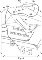
- the invention is disclosed in fig. 8 and corresponding passages of the description.
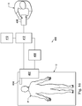
- the sensor device 20 is coupled at a proximal end 20a to the interrogation system 12 and at a distal end 20b to the interventional instrument 22. Although the sensor device 20 is shown extending entirely within or along the interventional instrument, in various alternative embodiments, the sensor device may extend only partially within or along the interventional instrument.
- the interventional instrument 22 is coupled to a control system 24 to receive, for example, power and communication signals.
- the sensor device 30 is coupled at a proximal end 30a to the interrogation system 12 and at a distal end 30b to the digitizing probe 23. Although the sensor device 30 is shown extending entirely within or along the probe 23, in various alternative embodiments, the sensor device may extend only partially within or along the probe.
- the digitizing probe 23 is coupled to the operated control system 24 to receive, for example, power and communication signals. The digitizing probe 23 may be used to identify and record navigational landmarks.
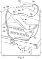
- the target fixture 26 is anchored to an anatomical structure of a patient anatomy.
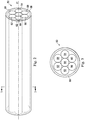
- the target fixture 26 includes connectors 28 for fixing a portion of one or more sensor devices 16, 18 to the target fixture and maintaining the fixed portions of the sensor devices in a predefined shape or pose.
- the sensor devices may be glued, mechanically held, or otherwise affixed within the target fixture.
- the target fixture may be a small aluminum plate with a plurality of tight-fitting grooves in which portions of the sensor devices are maintained in fixed kinematic relationships. Additional configurations for target fixtures with bone fixation devices are described in later embodiments.
- bending of the optical fiber When applied to a multicore fiber, bending of the optical fiber induces strain on the cores that can be measured by monitoring the wavelength shifts in each core.
- bending of the fiber induces different strains on each of the cores. These strains are a function of the local degree of bending of the fiber. For example, regions of the cores containing FBG's, if located at points where the fiber is bent, can thereby be used to determine the amount of bending at those points.
- These data combined with the known spacings of the FBG regions, can be used to reconstruct the shape of the fiber. From the shape of the sensor device, a position and orientation of the distal ends 16b, 18b, 20b, 30b or other axial portions of the sensor devices may be determined.
- the pose of the sensor device 16 at the target fixture may be determined in the reference frame of the reference fixture 14.
- the pose of the sensor device 18 at the target fixture 32b and the pose of the sensor device 20 at the target fixture 32c are determined with reference to the reference fixture 14.
- the shape information about the segment 604 and 606 may be combined to determine a pose for the target fixture 32b relative to the reference fixture 14.
- the miniature interrogator at target fixture 32b may interrogate the shape sensor 608 to determine the shape of the sensor 608 and the pose of the target fixture 32c with reference to the target fixture 32b.
- Data about the shape of the segment 608 and the pose of the target fixture 32c may be conveyed through the segments 604, 606 to the control system 27, for example, on a dedicated communication fiber or a selected core of a multi-core fiber, as an electrical signal, or wirelessly.
- the shape information about the segment 604, 606, 608 may be combined to determine a pose for the target fixture 32c relative to the reference fixture 14.
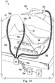
- FIG. 7 illustrates a sensor system 650 in accordance with an embodiment of the present disclosure.
- a linked sensor device 652 includes staggered segments 654, 656, 658.
- Segment 654 includes at least one optical fiber extending between the reference fixture 14, the target fixture 32a, the target fixture 32b, and the target fixture 32c. Gratings may extend only along the portion of segment 654 between target fixtures 32b and 32c.
- segment 654 is interrogated by the interrogator 12
- only shape information about the portion of the segment 654 between fixtures 32b and 32c is returned. This limited use of FBGs may reduce attenuation loss compared to what would be expected if gratings extended along the entire length of the segment 654. Non-grated fiber experiences relatively low signal loss.
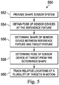
- the sensor device 754 extends between the reference fixture 14 and the target fixture 32b and a similar method is used to determine a refined pose of the target fixture 32b.
- the sensor device 756 extends between the reference fixture 14 and the target fixture 32c and a similar method is used to determine a refined pose of the target fixture 32c.
- the optical fiber shape sensors that comprise the sensor devices of this embodiment may be assembled in a ribbon configuration with a known spatial relationship between the optical fibers. Generally, greater separation between the sensor devices in a ribbon configuration contributes to improved roll measurements and thus improved pose measurements.
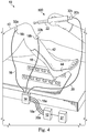
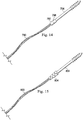
- FIG. 14 illustrates an optical fiber sensor device 790 attached to a coupling mechanism 792.
- Bone fixation hardware 794 is fitted with a coupling mechanism 796 that detachably connects to the coupling mechanism 792.
- the coupling mechanisms 792, 796 When connected to each other, the coupling mechanisms 792, 796 maintain a distal end 791 of the sensor device 790 in a fixed pose relative to the bone fixation hardware 794.
- the coupling mechanisms 792, 796 may connect to each other with any known coupling system including a clip, a clamp, a twist lock, a threaded connection, a magnetic connection, or a snap-fit connection.
- the coupling mechanisms 792, 796 may be detachable to allow the bone fixation hardware to become disconnected from the sensor device 790. With the coupling mechanisms of this embodiment, a target fixture and a sensor device may be quickly connected and disconnected.
- the robotic assembly 402 supports the interventional instrument system 404 and may comprise a kinematic structure of one or more non-servo controlled links (e.g., one or more links that may be manually positioned and locked in place, generally referred to as a set-up structure) and a robotic manipulator.
- the robotic assembly 402 includes plurality of actuators (e.g., motors) that drive inputs on the interventional instrument 404. These motors actively move in response to commands from the control system (e.g., control system 412).
- the display system 410 may display a virtual visualization image in which the actual location of the interventional instrument is registered (e.g., dynamically referenced) with preoperative or concurrent images to present the surgeon with a virtual image of the internal surgical site at the location of the tip of the surgical instrument.
- a virtual visualization image in which the actual location of the interventional instrument is registered (e.g., dynamically referenced) with preoperative or concurrent images to present the surgeon with a virtual image of the internal surgical site at the location of the tip of the surgical instrument.
- the control system 412 may further include a virtual visualization system to provide navigation assistance to the interventional instruments 404.
- Virtual navigation using the virtual visualization system is based upon reference to an acquired dataset associated with the three dimensional structure of the anatomical passageways. More specifically, the virtual visualization system processes images of the surgical site recorded and/or modeled using imaging technology such as computerized tomography (CT), magnetic resonance imaging (MRI), fluoroscopy, thermography, ultrasound, optical coherence tomography (OCT), thermal imaging, impedance imaging, laser imaging, nanotube X-ray imaging, digitizing probe acquisitions or the like.
- CT computerized tomography
- MRI magnetic resonance imaging
- fluoroscopy thermography
- ultrasound optical coherence tomography
- OCT optical coherence tomography
- thermal imaging impedance imaging
- laser imaging laser imaging
- nanotube X-ray imaging nanotube X-ray imaging
- the robotic interventional system 400 may further include optional operation and support systems (not shown) such as illumination systems, steering control systems, irrigation systems, and/or suction systems.
- the robotic system may include more than one robotic assembly and/or more than one operator input system.
- the exact number of manipulator assemblies will depend on the surgical procedure and the space constraints within the operating room, among other factors.
- the operator input systems may be collocated, or they may be positioned in separate locations. Multiple operator input systems allow more than one operator to control one or more manipulator assemblies in various combinations.
- Processor readable storage device examples include an electronic circuit; a semiconductor device, a semiconductor memory device, a read only memory (ROM), a flash memory, an erasable programmable read only memory (EPROM); a floppy diskette, a CD-ROM, an optical disk, a hard disk, or other storage device,
- the code segments may be downloaded via computer networks such as the Internet, intranet, etc.
Claims (11)
- System, Folgendes umfassend:eine erste Knochenfixierungsvorrichtung (32a);eine Instrumentenhalterung (32c);eine Halterung (14) für einen Formsensorbezug; undein geschlossenes Kettensensorsystem (700), Folgendes beinhaltend:eine erste Formsensorvorrichtung (710) mit einer optischen Faser, die konfiguriert ist, um sich zwischen die Halterung (14) für einen Formsensorbezug und die erste Knochenfixierungsvorrichtung (32a) zu koppeln, wobei der erste Formsensor mit einer optischen Faser konfiguriert ist, um erste Formdaten zum Bestimmen einer Haltung der ersten Knochenfixierungsvorrichtung bezüglich der Halterung für einen Formsensorbezug bereitzustellen;eine zweite Formsensorvorrichtung (712) mit einer optischen Faser, die konfiguriert ist, um sich zwischen die Halterung (14) für einen Formbezug und die Instrumentenhalterung (32c) zu koppeln, die an ein medizinisches Instrument gekoppelt ist, wobei der zweite Formsensor mit einer optischen Faser konfiguriert ist, um zweite Formdaten zum Bestimmen einer ersten Haltung der Instrumentenhalterung bezüglich der Halterung für einen Formsensorbezug bereitzustellen;eine dritte Formsensorvorrichtung (702) mit einer optischen Faser, die konfiguriert ist, um sich zwischen die erste Knochenfixierungsvorrichtung (32a) und die Instrumentenhalterung (32c) zu koppeln, wobei der dritte Formsensor mit einer optischen Faser konfiguriert ist, um dritte Formdaten zum Bestimmen einer zweiten Haltung der Instrumentenhalterung bezüglich der Halterung (14) für einen Formsensorbezug bereitzustellen; undein Steuersystem (27), das konfiguriert ist, um die erste Haltung und die zweite Haltung der Instrumentenhalterung (32c) zu kombinieren, um eine verfeinerte Haltung der Instrumentenhalterung bezüglich der Halterung (14) für einen Formsensorbezug zu bestimmen.
- System nach Anspruch 1, ferner umfassend ein chirurgisches Abdecktuch (720), wobei der erste Formsensor (710) mit einer optischen Faser in das chirurgische Abdecktuch integriert ist.
- System nach Anspruch 2, wobei die erste Knochenfixierungsvorrichtung (32a) in das chirurgische Abdecktuch (720) integriert ist.
- System nach Anspruch 1, wobei ein Positions- und Ausrichtungsversatz die erste und die zweite Formsensorvorrichtung (710, 712) mit einer optischen Faser an Kopplungen mit der Halterung (14) für einen Formsensorbezug trennt.
- System nach Anspruch 1, wobei das medizinische Instrument (22) eine Sonde ist, die angepasst ist, um Punktpositionen zu digitalisieren.
- System nach Anspruch 1, wobei das medizinische Instrument (22) eine Schneidvorrichtung beinhaltet.
- System nach Anspruch 1, wobei das medizinische Instrument (22) ein Ablationsinstrument beinhaltet.
- System nach Anspruch 1, wobei das medizinische Instrument (22) ein Bildgebungsinstrument beinhaltet.
- System nach Anspruch 1, wobei sich die zweite Formsensorvorrichtung (712) mit einer optischen Faser innerhalb eines Kabels erstreckt, das eine Stromversorgungskomponente oder eine Kommunikationskomponente beinhaltet.
- System nach Anspruch 1, wobei die erste Formsensorvorrichtung (710) mit einer optischen Faser konfiguriert ist, um Datensignale, die einen Instrumentenstatus, eine Instrumentenidentifikation, eine Nutzungszählung und/oder angewandte Kraft-Dehnungsinformationen beinhalten, zu übertragen.
- System nach Anspruch 1, wobei die erste Formsensorvorrichtung (710) mit einer optischen Faser lösbar mit der ersten Knochenfixierungsvorrichtung (32a) durch einen Kopplungsmechanismus (792, 796) gekoppelt ist.
Applications Claiming Priority (2)
| Application Number | Priority Date | Filing Date | Title |
|---|---|---|---|
| US201361876992P | 2013-09-12 | 2013-09-12 | |
| PCT/US2014/055137 WO2015038740A1 (en) | 2013-09-12 | 2014-09-11 | Shape sensor systems for localizing movable targets |
Publications (3)
| Publication Number | Publication Date |
|---|---|
| EP3043738A1 EP3043738A1 (de) | 2016-07-20 |
| EP3043738A4 EP3043738A4 (de) | 2017-04-19 |
| EP3043738B1 true EP3043738B1 (de) | 2019-12-11 |
Family
ID=52666261
Family Applications (1)
| Application Number | Title | Priority Date | Filing Date |
|---|---|---|---|
| EP14844589.3A Active EP3043738B1 (de) | 2013-09-12 | 2014-09-11 | Formsensorsysteme zur lokalisierung beweglicher ziele |
Country Status (6)
| Country | Link |
|---|---|
| US (1) | US10376321B2 (de) |
| EP (1) | EP3043738B1 (de) |
| JP (1) | JP6567532B2 (de) |
| KR (1) | KR102248497B1 (de) |
| CN (1) | CN105555205B (de) |
| WO (1) | WO2015038740A1 (de) |
Cited By (1)
| Publication number | Priority date | Publication date | Assignee | Title |
|---|---|---|---|---|
| WO2024028730A1 (en) * | 2022-08-01 | 2024-02-08 | Arthrex, Inc. | Spatial tracking of tools and instruments in an operating field |
Families Citing this family (17)
| Publication number | Priority date | Publication date | Assignee | Title |
|---|---|---|---|---|
| WO2017106003A1 (en) * | 2015-12-14 | 2017-06-22 | Intuitive Surgical Operations, Inc. | Apparatus and method for generating 3-d data for an anatomical target using optical fiber shape sensing |
| CN108472082B (zh) | 2015-12-29 | 2021-08-10 | 皇家飞利浦有限公司 | 用于医学导航的配准系统以及其操作方法 |
| JP6932727B2 (ja) * | 2016-05-23 | 2021-09-08 | マコ サージカル コーポレーション | 骨を切断するための医療装置 |
| CN114279363A (zh) * | 2016-07-08 | 2022-04-05 | 直观外科手术操作公司 | 用于安全的多芯纤维中冗余弯曲的计算 |
| US10132891B2 (en) * | 2016-09-16 | 2018-11-20 | General Electric Company | System and method for attenuation correction of a surface coil in a PET-MRI system |
| US10337893B2 (en) * | 2017-01-10 | 2019-07-02 | Parker-Hannifin Corporation | Optically powered sensor calibration data storage module |
| EP3420914A1 (de) * | 2017-06-30 | 2019-01-02 | Koninklijke Philips N.V. | Ultraschallsystem und verfahren |
| CN117503384A (zh) | 2017-06-28 | 2024-02-06 | 直观外科手术操作公司 | 用于将内窥镜图像数据集映射到三维体积上的系统 |
| US11129679B2 (en) * | 2017-11-14 | 2021-09-28 | Mako Surgical Corp. | Fiber optic tracking system |
| EP3755228B1 (de) * | 2018-02-22 | 2023-06-21 | Koninklijke Philips N.V. | Sensorbasierte formerkennung |
| EP3636140A1 (de) | 2018-10-10 | 2020-04-15 | Koninklijke Philips N.V. | System und verfahren zur sensorpositionierung und platzierung einer sensoranordnung |
| WO2020131576A1 (en) | 2018-12-18 | 2020-06-25 | Mako Surgical Corp. | Systems and methods for fiber optic tracking |
| US10973579B2 (en) | 2018-12-28 | 2021-04-13 | Industrial Technology Research Institute | Optical system |
| US20210330399A1 (en) * | 2020-04-28 | 2021-10-28 | Smith & Nephew, Inc. | Surgical tracking methods and fiber optic shape sensing devices thereof |
| WO2022125629A1 (en) * | 2020-12-09 | 2022-06-16 | Smith & Nephew, Inc. | Fiber optic cable for less invasive bone tracking |
| US20220409307A1 (en) * | 2021-06-25 | 2022-12-29 | DePuy Synthes Products, Inc. | Systems and methods for detecting skiving in surgical instruments |
| WO2024020069A1 (en) * | 2022-07-21 | 2024-01-25 | Intuitive Surgical Operations, Inc. | Shape localized flexible instrument |
Family Cites Families (25)
| Publication number | Priority date | Publication date | Assignee | Title |
|---|---|---|---|---|
| US6127672A (en) | 1997-05-23 | 2000-10-03 | Canadian Space Agency | Topological and motion measuring tool |
| GB9713018D0 (en) | 1997-06-20 | 1997-08-27 | Secr Defence | Optical fibre bend sensor |
| US6757582B2 (en) * | 2002-05-03 | 2004-06-29 | Carnegie Mellon University | Methods and systems to control a shaping tool |
| US20060013523A1 (en) | 2004-07-16 | 2006-01-19 | Luna Innovations Incorporated | Fiber optic position and shape sensing device and method relating thereto |
| US7772541B2 (en) | 2004-07-16 | 2010-08-10 | Luna Innnovations Incorporated | Fiber optic position and/or shape sensing based on rayleigh scatter |
| US7781724B2 (en) | 2004-07-16 | 2010-08-24 | Luna Innovations Incorporated | Fiber optic position and shape sensing device and method relating thereto |
| US8375808B2 (en) * | 2005-12-30 | 2013-02-19 | Intuitive Surgical Operations, Inc. | Force sensing for surgical instruments |
| US8945095B2 (en) | 2005-03-30 | 2015-02-03 | Intuitive Surgical Operations, Inc. | Force and torque sensing for surgical instruments |
| EP1898775B1 (de) * | 2005-06-21 | 2013-02-13 | Philips Electronics LTD | System und gerät für die navigierte therapie und diagnose |
| US7930065B2 (en) | 2005-12-30 | 2011-04-19 | Intuitive Surgical Operations, Inc. | Robotic surgery system including position sensors using fiber bragg gratings |
| CN200970224Y (zh) * | 2006-11-09 | 2007-11-07 | 上海大学 | 医用内窥镜本体三维定位系统 |
| CN101099657A (zh) * | 2007-07-13 | 2008-01-09 | 上海大学 | 细长柔性杆的空间形状检测装置和方法 |
| US7761937B2 (en) * | 2007-08-01 | 2010-07-27 | Foutz Gregory J | Timepiece shower head |
| WO2009155325A2 (en) * | 2008-06-18 | 2009-12-23 | Mako Surgical Corp. | Fiber optictracking system and method for tracking |
| US7720322B2 (en) | 2008-06-30 | 2010-05-18 | Intuitive Surgical, Inc. | Fiber optic shape sensor |
| DE102008052680A1 (de) | 2008-10-22 | 2010-04-29 | Surgitaix Ag | Vorrichtung zur kontrollierten Einstellung einer chirurgischen Positioniereinheit |
| US8488130B2 (en) | 2009-11-13 | 2013-07-16 | Intuitive Surgical Operations, Inc. | Method and system to sense relative partial-pose information using a shape sensor |
| US8957367B2 (en) | 2009-11-13 | 2015-02-17 | Intuitive Surgical Operations, Inc. | Shape sensor contained in a link of a kinematic chain with at least one pre-set perturbation and method to sense relative partial-pose information using the shape sensor |
| US9285246B2 (en) * | 2010-02-12 | 2016-03-15 | Intuitive Surgical Operations, Inc. | Method and system for absolute three-dimensional measurements using a twist-insensitive shape sensor |
| US8900131B2 (en) | 2011-05-13 | 2014-12-02 | Intuitive Surgical Operations, Inc. | Medical system providing dynamic registration of a model of an anatomical structure for image-guided surgery |
| EP2717771B1 (de) | 2011-06-10 | 2018-10-03 | Koninklijke Philips N.V. | Glasfasermessung zur bestimmung von echtzeit-veränderungen einer applikatorgeometrie für interventionelle therapie |
| EP2717774B1 (de) | 2011-06-10 | 2017-11-15 | Koninklijke Philips N.V. | Dynamische einschränkung mit optischer formmessung |
| CN103889259B (zh) * | 2011-10-21 | 2017-01-18 | 皇家飞利浦有限公司 | 用于医疗介入的体表反馈 |
| EP2744439B1 (de) * | 2011-10-26 | 2015-06-17 | Koninklijke Philips N.V. | Intelligenter werkzeughalter für eine optische formmessfaser |
| CN114343608A (zh) * | 2013-07-29 | 2022-04-15 | 直观外科手术操作公司 | 具有冗余感测的形状传感器系统 |
-
2014
- 2014-09-11 JP JP2016542094A patent/JP6567532B2/ja active Active
- 2014-09-11 CN CN201480050066.XA patent/CN105555205B/zh active Active
- 2014-09-11 EP EP14844589.3A patent/EP3043738B1/de active Active
- 2014-09-11 WO PCT/US2014/055137 patent/WO2015038740A1/en active Application Filing
- 2014-09-11 US US14/916,854 patent/US10376321B2/en active Active
- 2014-09-11 KR KR1020167006232A patent/KR102248497B1/ko active IP Right Grant
Non-Patent Citations (1)
| Title |
|---|
| None * |
Cited By (1)
| Publication number | Priority date | Publication date | Assignee | Title |
|---|---|---|---|---|
| WO2024028730A1 (en) * | 2022-08-01 | 2024-02-08 | Arthrex, Inc. | Spatial tracking of tools and instruments in an operating field |
Also Published As
| Publication number | Publication date |
|---|---|
| WO2015038740A1 (en) | 2015-03-19 |
| CN105555205A (zh) | 2016-05-04 |
| JP2016533849A (ja) | 2016-11-04 |
| US20160206384A1 (en) | 2016-07-21 |
| EP3043738A4 (de) | 2017-04-19 |
| US10376321B2 (en) | 2019-08-13 |
| EP3043738A1 (de) | 2016-07-20 |
| CN105555205B (zh) | 2019-10-22 |
| KR20160056884A (ko) | 2016-05-20 |
| JP6567532B2 (ja) | 2019-08-28 |
| KR102248497B1 (ko) | 2021-05-06 |
Similar Documents
| Publication | Publication Date | Title |
|---|---|---|
| EP3043738B1 (de) | Formsensorsysteme zur lokalisierung beweglicher ziele | |
| US20220133414A1 (en) | Shape sensor systems with redundant sensing | |
| US11871898B2 (en) | Systems and methods for interventional procedure planning | |
| US11779405B2 (en) | Systems and methods for entry point localization | |
| JP6620191B2 (ja) | 介入器具を追跡するための形状センサーシステム及びこのシステムの使用方法 | |
| EP2849670B1 (de) | Systeme zur registrierung einer medizinischen vorrichtung unter verwendung eines reduzierten suchraums |
Legal Events
| Date | Code | Title | Description |
|---|---|---|---|
| PUAI | Public reference made under article 153(3) epc to a published international application that has entered the european phase |
Free format text: ORIGINAL CODE: 0009012 |
|
| 17P | Request for examination filed |
Effective date: 20160308 |
|
| AK | Designated contracting states |
Kind code of ref document: A1 Designated state(s): AL AT BE BG CH CY CZ DE DK EE ES FI FR GB GR HR HU IE IS IT LI LT LU LV MC MK MT NL NO PL PT RO RS SE SI SK SM TR |
|
| AX | Request for extension of the european patent |
Extension state: BA ME |
|
| DAX | Request for extension of the european patent (deleted) | ||
| A4 | Supplementary search report drawn up and despatched |
Effective date: 20170320 |
|
| RIC1 | Information provided on ipc code assigned before grant |
Ipc: A61B 17/56 20060101ALI20170314BHEP Ipc: A61B 90/00 20160101AFI20170314BHEP |
|
| GRAP | Despatch of communication of intention to grant a patent |
Free format text: ORIGINAL CODE: EPIDOSNIGR1 |
|
| STAA | Information on the status of an ep patent application or granted ep patent |
Free format text: STATUS: GRANT OF PATENT IS INTENDED |
|
| INTG | Intention to grant announced |
Effective date: 20190726 |
|
| GRAS | Grant fee paid |
Free format text: ORIGINAL CODE: EPIDOSNIGR3 |
|
| GRAA | (expected) grant |
Free format text: ORIGINAL CODE: 0009210 |
|
| STAA | Information on the status of an ep patent application or granted ep patent |
Free format text: STATUS: THE PATENT HAS BEEN GRANTED |
|
| RIN1 | Information on inventor provided before grant (corrected) |
Inventor name: DUINDAM, VINCENT Inventor name: LARKIN, DAVID Q. Inventor name: DIMAIO, SIMON P. |
|
| AK | Designated contracting states |
Kind code of ref document: B1 Designated state(s): AL AT BE BG CH CY CZ DE DK EE ES FI FR GB GR HR HU IE IS IT LI LT LU LV MC MK MT NL NO PL PT RO RS SE SI SK SM TR |
|
| REG | Reference to a national code |
Ref country code: GB Ref legal event code: FG4D |
|
| REG | Reference to a national code |
Ref country code: CH Ref legal event code: EP |
|
| REG | Reference to a national code |
Ref country code: AT Ref legal event code: REF Ref document number: 1211386 Country of ref document: AT Kind code of ref document: T Effective date: 20191215 |
|
| REG | Reference to a national code |
Ref country code: DE Ref legal event code: R096 Ref document number: 602014058365 Country of ref document: DE |
|
| REG | Reference to a national code |
Ref country code: IE Ref legal event code: FG4D |
|
| REG | Reference to a national code |
Ref country code: NL Ref legal event code: MP Effective date: 20191211 |
|
| REG | Reference to a national code |
Ref country code: LT Ref legal event code: MG4D |
|
| PG25 | Lapsed in a contracting state [announced via postgrant information from national office to epo] |
Ref country code: SE Free format text: LAPSE BECAUSE OF FAILURE TO SUBMIT A TRANSLATION OF THE DESCRIPTION OR TO PAY THE FEE WITHIN THE PRESCRIBED TIME-LIMIT Effective date: 20191211 Ref country code: LV Free format text: LAPSE BECAUSE OF FAILURE TO SUBMIT A TRANSLATION OF THE DESCRIPTION OR TO PAY THE FEE WITHIN THE PRESCRIBED TIME-LIMIT Effective date: 20191211 Ref country code: GR Free format text: LAPSE BECAUSE OF FAILURE TO SUBMIT A TRANSLATION OF THE DESCRIPTION OR TO PAY THE FEE WITHIN THE PRESCRIBED TIME-LIMIT Effective date: 20200312 Ref country code: NO Free format text: LAPSE BECAUSE OF FAILURE TO SUBMIT A TRANSLATION OF THE DESCRIPTION OR TO PAY THE FEE WITHIN THE PRESCRIBED TIME-LIMIT Effective date: 20200311 Ref country code: FI Free format text: LAPSE BECAUSE OF FAILURE TO SUBMIT A TRANSLATION OF THE DESCRIPTION OR TO PAY THE FEE WITHIN THE PRESCRIBED TIME-LIMIT Effective date: 20191211 Ref country code: BG Free format text: LAPSE BECAUSE OF FAILURE TO SUBMIT A TRANSLATION OF THE DESCRIPTION OR TO PAY THE FEE WITHIN THE PRESCRIBED TIME-LIMIT Effective date: 20200311 Ref country code: LT Free format text: LAPSE BECAUSE OF FAILURE TO SUBMIT A TRANSLATION OF THE DESCRIPTION OR TO PAY THE FEE WITHIN THE PRESCRIBED TIME-LIMIT Effective date: 20191211 |
|
| PG25 | Lapsed in a contracting state [announced via postgrant information from national office to epo] |
Ref country code: HR Free format text: LAPSE BECAUSE OF FAILURE TO SUBMIT A TRANSLATION OF THE DESCRIPTION OR TO PAY THE FEE WITHIN THE PRESCRIBED TIME-LIMIT Effective date: 20191211 Ref country code: RS Free format text: LAPSE BECAUSE OF FAILURE TO SUBMIT A TRANSLATION OF THE DESCRIPTION OR TO PAY THE FEE WITHIN THE PRESCRIBED TIME-LIMIT Effective date: 20191211 |
|
| PG25 | Lapsed in a contracting state [announced via postgrant information from national office to epo] |
Ref country code: AL Free format text: LAPSE BECAUSE OF FAILURE TO SUBMIT A TRANSLATION OF THE DESCRIPTION OR TO PAY THE FEE WITHIN THE PRESCRIBED TIME-LIMIT Effective date: 20191211 |
|
| PG25 | Lapsed in a contracting state [announced via postgrant information from national office to epo] |
Ref country code: ES Free format text: LAPSE BECAUSE OF FAILURE TO SUBMIT A TRANSLATION OF THE DESCRIPTION OR TO PAY THE FEE WITHIN THE PRESCRIBED TIME-LIMIT Effective date: 20191211 Ref country code: CZ Free format text: LAPSE BECAUSE OF FAILURE TO SUBMIT A TRANSLATION OF THE DESCRIPTION OR TO PAY THE FEE WITHIN THE PRESCRIBED TIME-LIMIT Effective date: 20191211 Ref country code: NL Free format text: LAPSE BECAUSE OF FAILURE TO SUBMIT A TRANSLATION OF THE DESCRIPTION OR TO PAY THE FEE WITHIN THE PRESCRIBED TIME-LIMIT Effective date: 20191211 Ref country code: RO Free format text: LAPSE BECAUSE OF FAILURE TO SUBMIT A TRANSLATION OF THE DESCRIPTION OR TO PAY THE FEE WITHIN THE PRESCRIBED TIME-LIMIT Effective date: 20191211 Ref country code: EE Free format text: LAPSE BECAUSE OF FAILURE TO SUBMIT A TRANSLATION OF THE DESCRIPTION OR TO PAY THE FEE WITHIN THE PRESCRIBED TIME-LIMIT Effective date: 20191211 Ref country code: PT Free format text: LAPSE BECAUSE OF FAILURE TO SUBMIT A TRANSLATION OF THE DESCRIPTION OR TO PAY THE FEE WITHIN THE PRESCRIBED TIME-LIMIT Effective date: 20200506 |
|
| PG25 | Lapsed in a contracting state [announced via postgrant information from national office to epo] |
Ref country code: SM Free format text: LAPSE BECAUSE OF FAILURE TO SUBMIT A TRANSLATION OF THE DESCRIPTION OR TO PAY THE FEE WITHIN THE PRESCRIBED TIME-LIMIT Effective date: 20191211 Ref country code: IS Free format text: LAPSE BECAUSE OF FAILURE TO SUBMIT A TRANSLATION OF THE DESCRIPTION OR TO PAY THE FEE WITHIN THE PRESCRIBED TIME-LIMIT Effective date: 20200411 Ref country code: SK Free format text: LAPSE BECAUSE OF FAILURE TO SUBMIT A TRANSLATION OF THE DESCRIPTION OR TO PAY THE FEE WITHIN THE PRESCRIBED TIME-LIMIT Effective date: 20191211 |
|
| REG | Reference to a national code |
Ref country code: DE Ref legal event code: R097 Ref document number: 602014058365 Country of ref document: DE |
|
| REG | Reference to a national code |
Ref country code: AT Ref legal event code: MK05 Ref document number: 1211386 Country of ref document: AT Kind code of ref document: T Effective date: 20191211 |
|
| PLBE | No opposition filed within time limit |
Free format text: ORIGINAL CODE: 0009261 |
|
| STAA | Information on the status of an ep patent application or granted ep patent |
Free format text: STATUS: NO OPPOSITION FILED WITHIN TIME LIMIT |
|
| PG25 | Lapsed in a contracting state [announced via postgrant information from national office to epo] |
Ref country code: DK Free format text: LAPSE BECAUSE OF FAILURE TO SUBMIT A TRANSLATION OF THE DESCRIPTION OR TO PAY THE FEE WITHIN THE PRESCRIBED TIME-LIMIT Effective date: 20191211 |
|
| 26N | No opposition filed |
Effective date: 20200914 |
|
| PG25 | Lapsed in a contracting state [announced via postgrant information from national office to epo] |
Ref country code: AT Free format text: LAPSE BECAUSE OF FAILURE TO SUBMIT A TRANSLATION OF THE DESCRIPTION OR TO PAY THE FEE WITHIN THE PRESCRIBED TIME-LIMIT Effective date: 20191211 Ref country code: SI Free format text: LAPSE BECAUSE OF FAILURE TO SUBMIT A TRANSLATION OF THE DESCRIPTION OR TO PAY THE FEE WITHIN THE PRESCRIBED TIME-LIMIT Effective date: 20191211 |
|
| PG25 | Lapsed in a contracting state [announced via postgrant information from national office to epo] |
Ref country code: IT Free format text: LAPSE BECAUSE OF FAILURE TO SUBMIT A TRANSLATION OF THE DESCRIPTION OR TO PAY THE FEE WITHIN THE PRESCRIBED TIME-LIMIT Effective date: 20191211 |
|
| PG25 | Lapsed in a contracting state [announced via postgrant information from national office to epo] |
Ref country code: PL Free format text: LAPSE BECAUSE OF FAILURE TO SUBMIT A TRANSLATION OF THE DESCRIPTION OR TO PAY THE FEE WITHIN THE PRESCRIBED TIME-LIMIT Effective date: 20191211 |
|
| PG25 | Lapsed in a contracting state [announced via postgrant information from national office to epo] |
Ref country code: MC Free format text: LAPSE BECAUSE OF FAILURE TO SUBMIT A TRANSLATION OF THE DESCRIPTION OR TO PAY THE FEE WITHIN THE PRESCRIBED TIME-LIMIT Effective date: 20191211 |
|
| REG | Reference to a national code |
Ref country code: CH Ref legal event code: PL |
|
| GBPC | Gb: european patent ceased through non-payment of renewal fee |
Effective date: 20200911 |
|
| REG | Reference to a national code |
Ref country code: BE Ref legal event code: MM Effective date: 20200930 |
|
| PG25 | Lapsed in a contracting state [announced via postgrant information from national office to epo] |
Ref country code: LU Free format text: LAPSE BECAUSE OF NON-PAYMENT OF DUE FEES Effective date: 20200911 |
|
| PG25 | Lapsed in a contracting state [announced via postgrant information from national office to epo] |
Ref country code: FR Free format text: LAPSE BECAUSE OF NON-PAYMENT OF DUE FEES Effective date: 20200930 |
|
| PG25 | Lapsed in a contracting state [announced via postgrant information from national office to epo] |
Ref country code: GB Free format text: LAPSE BECAUSE OF NON-PAYMENT OF DUE FEES Effective date: 20200911 Ref country code: IE Free format text: LAPSE BECAUSE OF NON-PAYMENT OF DUE FEES Effective date: 20200911 Ref country code: LI Free format text: LAPSE BECAUSE OF NON-PAYMENT OF DUE FEES Effective date: 20200930 Ref country code: CH Free format text: LAPSE BECAUSE OF NON-PAYMENT OF DUE FEES Effective date: 20200930 Ref country code: BE Free format text: LAPSE BECAUSE OF NON-PAYMENT OF DUE FEES Effective date: 20200930 |
|
| PG25 | Lapsed in a contracting state [announced via postgrant information from national office to epo] |
Ref country code: TR Free format text: LAPSE BECAUSE OF FAILURE TO SUBMIT A TRANSLATION OF THE DESCRIPTION OR TO PAY THE FEE WITHIN THE PRESCRIBED TIME-LIMIT Effective date: 20191211 Ref country code: MT Free format text: LAPSE BECAUSE OF FAILURE TO SUBMIT A TRANSLATION OF THE DESCRIPTION OR TO PAY THE FEE WITHIN THE PRESCRIBED TIME-LIMIT Effective date: 20191211 Ref country code: CY Free format text: LAPSE BECAUSE OF FAILURE TO SUBMIT A TRANSLATION OF THE DESCRIPTION OR TO PAY THE FEE WITHIN THE PRESCRIBED TIME-LIMIT Effective date: 20191211 |
|
| PG25 | Lapsed in a contracting state [announced via postgrant information from national office to epo] |
Ref country code: MK Free format text: LAPSE BECAUSE OF FAILURE TO SUBMIT A TRANSLATION OF THE DESCRIPTION OR TO PAY THE FEE WITHIN THE PRESCRIBED TIME-LIMIT Effective date: 20191211 |
|
| P01 | Opt-out of the competence of the unified patent court (upc) registered |
Effective date: 20230330 |
|
| PGFP | Annual fee paid to national office [announced via postgrant information from national office to epo] |
Ref country code: DE Payment date: 20230928 Year of fee payment: 10 |