EP3043630A1 - Work apparatus for substrate - Google Patents
Work apparatus for substrate Download PDFInfo
- Publication number
- EP3043630A1 EP3043630A1 EP13892861.9A EP13892861A EP3043630A1 EP 3043630 A1 EP3043630 A1 EP 3043630A1 EP 13892861 A EP13892861 A EP 13892861A EP 3043630 A1 EP3043630 A1 EP 3043630A1
- Authority
- EP
- European Patent Office
- Prior art keywords
- support pin
- gripping device
- gripping
- work
- support
- Prior art date
- Legal status (The legal status is an assumption and is not a legal conclusion. Google has not performed a legal analysis and makes no representation as to the accuracy of the status listed.)
- Granted
Links
Images


Classifications
-
- H—ELECTRICITY
- H05—ELECTRIC TECHNIQUES NOT OTHERWISE PROVIDED FOR
- H05K—PRINTED CIRCUITS; CASINGS OR CONSTRUCTIONAL DETAILS OF ELECTRIC APPARATUS; MANUFACTURE OF ASSEMBLAGES OF ELECTRICAL COMPONENTS
- H05K13/00—Apparatus or processes specially adapted for manufacturing or adjusting assemblages of electric components
- H05K13/0061—Tools for holding the circuit boards during processing; handling transport of printed circuit boards
- H05K13/0069—Holders for printed circuit boards
-
- H—ELECTRICITY
- H05—ELECTRIC TECHNIQUES NOT OTHERWISE PROVIDED FOR
- H05K—PRINTED CIRCUITS; CASINGS OR CONSTRUCTIONAL DETAILS OF ELECTRIC APPARATUS; MANUFACTURE OF ASSEMBLAGES OF ELECTRICAL COMPONENTS
- H05K13/00—Apparatus or processes specially adapted for manufacturing or adjusting assemblages of electric components
- H05K13/04—Mounting of components, e.g. of leadless components
- H05K13/0404—Pick-and-place heads or apparatus, e.g. with jaws
-
- H—ELECTRICITY
- H05—ELECTRIC TECHNIQUES NOT OTHERWISE PROVIDED FOR
- H05K—PRINTED CIRCUITS; CASINGS OR CONSTRUCTIONAL DETAILS OF ELECTRIC APPARATUS; MANUFACTURE OF ASSEMBLAGES OF ELECTRICAL COMPONENTS
- H05K13/00—Apparatus or processes specially adapted for manufacturing or adjusting assemblages of electric components
- H05K13/0061—Tools for holding the circuit boards during processing; handling transport of printed circuit boards
-
- H—ELECTRICITY
- H05—ELECTRIC TECHNIQUES NOT OTHERWISE PROVIDED FOR
- H05K—PRINTED CIRCUITS; CASINGS OR CONSTRUCTIONAL DETAILS OF ELECTRIC APPARATUS; MANUFACTURE OF ASSEMBLAGES OF ELECTRICAL COMPONENTS
- H05K13/00—Apparatus or processes specially adapted for manufacturing or adjusting assemblages of electric components
- H05K13/04—Mounting of components, e.g. of leadless components
- H05K13/0404—Pick-and-place heads or apparatus, e.g. with jaws
- H05K13/0408—Incorporating a pick-up tool
Definitions
- the present invention relates to a board work device provided with a work head for performing work with respect to a circuit board, a mounting member on which the work head is mounted, and a movement device for moving the mounting member to any position.
- the circuit board when performing work with respect to a circuit board using a board work device, the circuit board is supported and fixed from below using multiple support pins or the like. To appropriately fix the circuit board, it is desirable to change the layout position of the multiple support pins based on the shape of the circuit board.
- board work devices provided with a support pin gripping device for gripping a support pin, wherein the layout position of board pins is changed by the support pin gripping device.
- a support pin gripper device is integrated into the work head.
- the work head is usually capable of being moved to any position on the base of board work device by a moving device or the like.
- the support pin gripper device can also move to any position on the base of the board work device, and it is possible to suitably change the set position of the support pins.
- Patent literature 1 WO2005/081611
- exchanging to a dispenser head means that it is no longer possible to change the set position of support pins.
- equipment costs increase.
- the present invention takes account of these issues, and an object thereof is to provide a board work device that allows the set position of support pins to be changed even when exchanging work heads, and while curtailing increases in equipment costs.
- the board work device of Claim 1 comprises: a work head that performs work with respect to a circuit board; a mounting member on which the work head is mounted; a moving device that moves the mounting member to any position; and a support pin gripping device that grips a support pin, which supports a circuit board, in order to attach the support pin to a pin support member; wherein the support pin gripping device is mounted on a side of the mounting member opposite to the side of the mounting member on which the work head is mounted.
- the board work device of Claim 2 is the board work device according to Claim 1, wherein the support pin gripping device includes multiple gripping members with a protrusion section formed on an end thereof; and a holding body that holds the multiple gripping members such that the protruding sections of the respective gripping members are moved closer to each other or further apart from each other; and wherein the support pin gripping device grips the support pin by the protruding sections of the multiple gripping members moving closer to each other, and, instead of the support pin, grips a member which is different from the support pin, in which is formed a recess into which the protruding section can fit, by the protruding sections of the multiple gripping members moving closer to each other and the protruding section fitting into the recess.
- the board work device of Claim 3 is the board work device according to Claim 2, wherein the support pin gripping device includes a contacting member provided on the holding body that contacts the member which is different from the support pin when the protruding section is fitted into the recess.
- the board work device of Claim 4 is the board work device according to Claim 3, wherein the contacting member does not contact the support pin which is gripped by the support pin gripping device.
- the board work device of Claim 5 is the board work device according to any one of Claims 1 to 4, wherein the support pin gripping device is detachably mounted on the mounting member.
- the support pin gripping device is mounted on a surface of the mounting member on the opposite side to the surface of the mounting member to which the work head is mounted.
- the support pin gripping device is continuously mounted on the mounting member even when work heads are exchanged, so there is no need to integrate a support pin gripping device into each work head.
- This curtails increases in equipment costs while allowing the arrangement position of support pins to be changed when work heads are exchanged.
- the support pin gripping device grips not only support pins, but a member which is different from a support pin in which a recess is formed. This allows the support pin gripping device to perform a wide variety of work, thereby improving practicality.
- a contacting member is provided on the holding body, and the contacting member contacts the member, which is different from a support pin, which is gripped by the support pin gripping device.
- the support pin gripping device is designed for appropriately gripping a support pin, when the support pin gripping device grips a member which is different from a support pin, there is a concern that the member may wobble.
- the contacting section contacts the member, which is different from a support pin, which is gripped by the support pin gripping device.
- the contacting member does not contact the support pin which is gripped by the support pin gripping device. Because the support pin gripping device is designed for appropriately gripping a support pin, when the support pin gripping device grips a support pin, there is no concern about the support pin wobbling. Thus, by preventing unnecessary contact with the support pin for which there is no concern with regard to wobbling, it is possible to appropriately grip the support pin by the support pin gripping device.
- the support pin gripping device is detachably mounted on the mounting member.
- the mounting member By this, for example, it is possible to mount a device with different functionality to the support pin gripping device on the mounting member, thus allowing a greater variety of work to be performed by the board work device.
- Fig. 1 shows board work device 10 that is an embodiment of the present invention.
- Board work device 10 is a device for performing mounting work of electronic components onto a circuit board.
- Board work device 10 is provided with conveyance device 20, supply device 22, case supply device 23, mounting head 24, mounting head moving device (hereinafter sometimes referred to as "moving device") 26, and support pin gripping device 28.
- Conveyance device 20 has a pair of conveyor belts 30 extending in the X-axis direction and an electromagnetic motor (not shown) for turning the conveyor belts 30.
- Circuit board 34 is supported by this pair of conveyor belts 30 and is conveyed in the X-axis direction by the driving of the electromagnetic motor.
- conveyance device 20 has board holding device 36 which fixedly holds circuit board 34 supported by conveyor belts 30 at a predetermined position.
- board holding device 36 has multiple support pins 38 and pin supporting member 40.
- Pin supporting member 40 is a flat plate formed from magnetic material and is provided between the pair of conveyor belts 30.
- a magnet (not shown) is provided on the bottom surface of support pins 38.
- support pins 38 are fixed on the upper surface of pin supporting member 40 by magnetic force. Also, each support pin 38 is movable in the vertical direction, and by the movement upwards of support pins 38, circuit board 34 is raised. Also, edge sections of raised circuit board 34 contact a retaining section (not shown), and by being sandwiched between the retaining section and support pins 38, circuit board 34 is fixedly held in the predetermined position.
- support pins 38 are fixed to pin supporting member 40 by magnetic force, they are detachable from pin supporting member 40.
- support pins 38 are fixed to any position on pin supporting member 40 based on the shape and so on of circuit board 34.
- there is soft support pin 38a with a tip section formed from a soft material and hard support pin 38b with a tip section formed from a hard material.
- hard support pins 38b are used when supporting circuit board 34.
- soft support pins 38a are used when it is difficult to support circuit board 34 using hard support pins 38b due to the location of pre-mounted components which are close to each other and so on.
- support pin storage device 46 for storing support pins 38 is provided next to conveyance device 20.
- Bulk feeder 50 of the present embodiment is configured from component case (refer to fig. 7 ) 52, and a supply passage (not shown). Multiple electronic components are stored in a loose state in component case 52, and the electronic components stored in component case 52 are arranged in a single line in the supply passage. Further, the electronic components arranged in a single line are guided to a supply position so as to be supplied to the supply position.
- component case 52 is exchangeable so as to allow component replenishment, component exchange, and so on.
- case transfer window 56 is formed in the upper surface of bulk feeder 50, and a component case 52 which has become unnecessary in bulk feeder 50 are ejected from case transfer window 56.
- a required component case 52 is inserted from case transfer window 56.
- case transfer window 56 By this, for example, by ejecting a component case 52 which has become empty from case transfer window 56 and inserting a component case 52 full of electronic components from case transfer window, bulk feeder 50 is replenished with electronic components.
- Case supply device 23 is a device for supplying component cases 52 and is provided next to bulk feeder 50. Multiple component cases 52 are stored in case supply device 23, and any case out of the multiple component cases 52 can be ejected from case transfer window 58. Also, by inserting component case 52 via case transfer window 58, that component case 52 is stored inside case supply device 23.
- Mounting head 24 mounts electronic components on a circuit board.
- mounting head 24 has suction nozzle 60 provided on a lower end thereof.
- Suction nozzle 60 is connected to a positive/negative pressure supply device (not shown) via a negative pressure air and positive pressure air passage.
- Suction nozzle 60 picks up and holds an electronic component using negative pressure, and releases the held electronic component using positive pressure.
- mounting head 24 has a raising/lowering device (not shown) that raises/lowers suction nozzle 60. Mounting head 24 changes the vertical position of a held electronic component by the raising/lowering device.
- Moving device 26 moves mounting head 24 to any position on base 62.
- moving device 26 is configured from X-axis direction slide mechanism 70 and Y-axis direction slide mechanism 72.
- Y-axis direction slide mechanism 72 has a pair of Y-axis direction guide rails 74, and that pair of Y-axis direction guide rails 74 is provided extending in the Y-axis direction.
- X-axis direction slide mechanism 70 has X-axis direction guide rail 76, and that X-axis direction guide rail 76 extends in the X-axis direction on the pair of Y-axis direction guide rails 74.
- Y-axis direction slide mechanism 72 has an electromagnetic motor (not shown), and X-axis direction guide rail 76 is moved to any position in the Y-axis direction by the driving of the electromagnetic motor.
- X-axis direction guide rail 76 holds slider 78 as to be movable along its own axis.
- X-axis direction slide mechanism 70 has electromagnetic motor (not shown), and slider 78 is moved to any position in the X-axis direction by the driving of the electromagnetic motor.
- Mounting head 24 is mounted on slider 78. According to such a structure, mounting head 24 is moved to any position on base 62 by moving device 26. Note that, mounting head 24 is attachable/detachable to/from slider 78 with a single touch. By this, it is possible to change to different types of work heads such as a dispenser head.
- Support pin gripping device 28 is a device for gripping a support pin 38. As shown in fig. 3 , support pin gripping device 28 is provided on the side of slider 78 opposite to the side of slider 78 on which mounting head 24 is mounted, and has holding tool 80, slide mechanism 82, and main body 84. Holding tool 80 is configured from a pair of gripping claws 86 and holding body 88. Protruding section 92 is formed on the tip of the pair of gripping claws 86, and the protruding sections 92 face each other. Holding body 88 holds the pair of gripping claws 86 such that protruding sections 92 move towards each other or apart from each other.
- protruding sections 92 of the pair of gripping claws 86 move closer to each other, thus holding tool 80 grips support pin 38. Also, depending on positive pressure from the positive/negative pressure supply device, protruding sections 92 of the pair of gripping claws 86 move apart from each other, thus holding tool 80 releases support pin 38.
- soft support pin 38a and hard support pin 38b are configured from main body 100 and tip section 102.
- the shape of tip section 102 differs between soft support pin 38a and hard support pin 38b, but the shape of main body 100 is the same for soft support pin 38a and hard support pin 38b.
- Main body 100 is a stepped cylinder configured from first outer section 104, second outer section 106, and third outer section 108.
- First outer section 104 is positioned at the base of main body 100.
- Second outer section 106 is positioned on the upper surface of first outer section 104, and the diameter of second outer section 106 is smaller than the diameter of first outer section 104.
- Third outer section 108 is positioned on the upper surface of second outer section 106, and the diameter of third outer section 108 is larger than the diameter of second outer section 106.
- semi-circular cutout 110 is formed in protruding section 92 of gripping claw 86, and the internal diameter of that semi-circular cutout 110 is slightly larger than the external diameter of second outer section 106.
- protruding sections 92 of the pair of gripping claws 86 move closer to each other depending on the elastic force of a coil spring (not shown). Accordingly, as shown in fig. 5 , by protruding sections 92 of the pair of gripping claws 86 moving closer to each other such that second outer section 106 is sandwiched between cutouts 110, soft support pin 38a or hard support pin 38b is gripped by holding tool 80.
- protruding sections 92 of the pair of gripping claws 86 move apart from each other against the elastic force of the coil spring depending on positive pressure from the negative/positive pressure supply device. By this, a held soft support pin 38a or hard support pin 38b is released from holding tool 80.
- slide mechanism 82 holds holding tool 80 so as to be slidable in a vertical direction, and holding tool 80 slides up and down by an electromagnetic motor (not shown) being driven.
- support pin gripping device 28 changes the vertical position of a soft support pin 38a or a hard support pin 38b held by holding tool 80.
- check sensor 112 is provided on a side surface of holding tool 80, and using the sensor it is judged whether or not holding tool 80 is appropriately gripping soft support pin 38a or hard support pin 38b.
- holding tool 80 is capable of gripping not only soft support pin 38a and hard support pin 38b, but also of gripping component case 52 of bulk feeder 50.
- recess 116 is formed in both sides on the upper edge section of component case 52.
- Recess 116 is a shape such that protruding section 92 of the pair of gripping claws 86 of holding tool 80 is capable of engaging with recess 116, and protruding sections 92 enter recesses 116 by protruding sections 92 moving closer to each other.
- component case 52 is gripped by holding tool 80. In this way, holding tool 80 is capable of gripping not only support pin 38, but also component case 52.
- a pair of contacting members 118 is attached to holding body 88 of holding tool 80, and shifting of component case 52 held by holding tool 80 is prevented by this pair of contacting members 118.
- the pair of contacting members 118 is attached to a lower end of holding body 88 so as to sandwich the movement region of the pair of gripping claws 86.
- the pair of contacting members 118 contact an upper edge of component case 52 when component case 52 is gripped by holding tool 80. By this, shifting of component case 52 held by holding tool 80 is prevented.
- contacting members 118 do not contact soft support pin 38a or hard support pin 38b held by holding tool 80. This is because soft support pin 38a and hard support pin 38b are reliably sandwiched due to cutouts 110, so there is no need to prevent shifting.
- main body 84 of support pin gripping device 28 is capable of being attached/detached to/from slider 78 with a single touch.
- two feet 120 are provided on the lower section of the rear surface of main body 84, and engaging block 122 is provided on the upper section of main body 84.
- two foot supporting sections 124 and two engaging rollers 126 are provided on the lower section of slider 78, and lock mechanism 128 is provided on the upper section of slider 78.
- the lower end of foot 120 is wedge-shaped so as to engage with the upper end of foot supporting section 124 which is V-shaped.
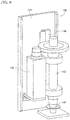
- slider 78 By removing support pin gripping device 28 from slider 78, various devices can be mounted on slider 78. Specifically, it is possible to mount an electronic component pickup/holding device, a viscous fluid dispensing device, or the like, on slider 78 instead of support pin gripping device 28.
- electronic component pickup/holding device 130 is configured from pickup rod 132, rotating mechanism 134, slide mechanism 136, and main body 138.
- Suction nozzle 140 is attached to the lower end of pickup rod 132, and suction nozzle 140 picks up and holds, or releases, an electronic component using respectively negative pressure and positive pressure supplied from a positive/negative pressure supply device. Note that, suction nozzle 140 is a nozzle with a relatively large diameter which can thus hold relatively large electronic components.
- Rotating mechanism 134 rotates pickup rod 132 about its own central axis.
- Slide mechanism 136 holds pickup rod 132 and rotating mechanism 134 so as to be slidable in the vertical direction, with the vertical position of pickup rod 132 and rotating mechanism 134 being changed by the driving of an electromagnetic motor (not shown).
- Main body 138 has the same structure as main body 84 of support pin gripping device 28, and is capable of being attached/detached to/from slider 78 with a single touch.
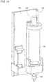
- viscous fluid dispensing device 150 is configured from syringe 152, slide mechanism, and main body 156.
- Dispensing nozzle 158 is attached to a lower end of syringe 152, and dispensing nozzle 158 dispenses a viscous fluid stored inside syringe 152 by the supply of positive pressure from the positive/negative pressure supply device.
- Slide mechanism 154 holds syringe 152 so as to be slidable in the vertical direction, with the vertical position of syringe 152 being changed by the driving of an electromagnetic motor (not shown).
- Main body 136 has the same structure as main body 84 of support pin gripping device 28, and is capable of being attached/detached to/from slider 78 with a single touch.
- support pin gripping device 28 moves above support pin 38 fixed on pin supporting member 40 by magnetic force, and grips support pin 38 using holding tool 80.
- support pin gripping device 28 moves above pin supporting member 40 where a support pin 38 is not fixed, and mounts the gripped support pin 38 on pin supporting member 40.
- support pins 38 are imaged by a camera (not shown) that images board marks on circuit board 34, thus allowing the arrangement position of support pins 38 to be checked. Further, in a case in which the actual arrangement position differs from the planned arrangement position, correction of the arrangement position can be performed based on the image data.
- pin support surface In cases in which many electronic components have been mounted on the surface of the circuit board which is the work target which is supported by support pins 38 (hereinafter sometimes referred to as "pin support surface"), exchange of support pins 38 is performed.
- circuit boards are usually supported by hard support pins 38b, hard support pins 38b are fixed to pin supporting member 40.
- the intervals between pre-mounted components become small, meaning that there is a concern about hard support pins 38b contacting pre-mounted components, thus damaging the pre-mounted components.
- hard support pins 38b mounted on the pin supporting member 40 are exchanged with soft support pins 38a.
- soft support pins 38a are stored in support pin storage device 46.
- support pin gripping device 28 moves above a hard support pin 38b which is fixed to pin supporting member 40 by magnetic force, and grips the hard support pin 38b using holding tool 80.
- support pin gripping device 28 moves above support pin storage device 46 and stores the gripped hard support pin 38b in support pin storage device 46.
- support pin gripping device 28 moves above a soft support pin 38a stored in support pin storage device 46 and grips the soft support pin 38a using holding tool 80.
- support pin gripping device 28 moves above a predetermined position on pin supporting member 40 and mounts the gripped soft support pin 38a on pin supporting member 40.
- component case 52 is changed by support pin gripping device 28.
- bulk feeder 50 ejects a component case 52 which has become unnecessary from case transfer window 56.
- support pin gripping device 28 moves above case transfer window 56 of bulk feeder 50 and grips component case 52 using holding tool 80.
- support pin gripping device 28 moves above case transfer window 58 of case supply device 23 and inserts the gripped component case 52 into case transfer window 58.
- case supply device 23 stores the inserted component case 52 internally. Then, case supply device 23 ejects a specified component case 52 from case transfer window 58.
- support pin gripping device 28 moves above case transfer window 58 of case supply device 23 and grips component case 52 using holding tool 80. Then, according to instructions of the control device, support pin gripping device 28 moves above case transfer window 56 of bulk feeder 50 and inserts the gripped component case 52 into case transfer window 56.
- bulk feeder 50 stores the inserted component case 52 internally. By this, replenishment of electronic components to bulk feeder 50, or exchange of electronic components supplied by bulk feeder 50, is performed.
- board work device 10 is an example of a board work device.
- Mounting head 24 is an example of a mounting head.
- Moving device 26 is an example of a moving device.
- Support pin gripping device 28 is an example of a support pin gripping device.
- Circuit board 34 is an example of a circuit board.
- Support pin 38 is an example of a support pin.
- Pin supporting member 49 is an example of a pin supporting member.
- Component case 52 is an example of a member which is different from a support pin.
- Slider 78 is an example of a mounting member.
- Gripping claw 86 is an example of a gripping claw.
- Holding body 88 is an example of a holding body.
- Protruding section 92 is an example of a protruding section.
- Recess 116 is an example of a recess.
- Contacting member 118 is an example of a contacting member.
- component case 52 is used as a member which is different from support pin 38 and which is capable of being gripped by holding tool 80, but various members may be used. However, it is necessary for a recess into which protruding section 92 of gripping claw 86 is capable of fitting to be formed in the member.
- a positive/negative pressure supply device is used as the drive source of gripping claws 86 of holding tool 80, but various driving sources may be used, such as electromagnetic motors, hydraulic actuators, and the like.
- support pin gripping device 28 is attachable/detachable to/from slider 78 with a single touch using lock mechanism 128, but support pin gripping device 28 may be attachable/detachable to/from slider 78 with a single touch using various mechanisms.
- the function of being attachable/detachable with a single touch is a function whereby support pin gripping device is attached to, or detached from, slider 78 without using tools or the like and with good repeatability.
- the attachment/detachment of support pin gripping device 28 to/from slider 78 may be performed using tools or the like.
- support pin gripping device 28 may be mounted on slider 78 using bolts or the like.
Landscapes
- Engineering & Computer Science (AREA)
- Manufacturing & Machinery (AREA)
- Microelectronics & Electronic Packaging (AREA)
- Supply And Installment Of Electrical Components (AREA)
Description
- The present invention relates to a board work device provided with a work head for performing work with respect to a circuit board, a mounting member on which the work head is mounted, and a movement device for moving the mounting member to any position.
- Conventionally, when performing work with respect to a circuit board using a board work device, the circuit board is supported and fixed from below using multiple support pins or the like. To appropriately fix the circuit board, it is desirable to change the layout position of the multiple support pins based on the shape of the circuit board. Thus, there are board work devices provided with a support pin gripping device for gripping a support pin, wherein the layout position of board pins is changed by the support pin gripping device. With the board work device disclosed in the patent literature below, a support pin gripper device is integrated into the work head. The work head is usually capable of being moved to any position on the base of board work device by a moving device or the like. Thus, the support pin gripper device can also move to any position on the base of the board work device, and it is possible to suitably change the set position of the support pins.
- Patent literature 1:
WO2005/081611 - According to the board work device disclosed in the above patent literature, it is possible to suitably change the set position of support pins. However, often work heads are detachably attached to a mounting member of a moving device, such that exchange and so on of work heads is possible. In other words, for example, in a case in which a mounting head is mounted on the mounting member, the mounting head can be removed from the mounting member, and a dispenser head can be mounted on the mounting member instead of the mounting head. Thus, instead of performing work of mounting electronic components onto a circuit board, it is possible to perform application work of a viscous fluid onto the circuit board. However, in a case in which the support pin gripping device is integrated into the mounting head, exchanging to a dispenser head means that it is no longer possible to change the set position of support pins. Also, for example, if a support pin gripping device is integrated not only into the mounting head, but also into the dispenser head, equipment costs increase. The present invention takes account of these issues, and an object thereof is to provide a board work device that allows the set position of support pins to be changed even when exchanging work heads, and while curtailing increases in equipment costs.
- To solve the above problem, the board work device of
Claim 1 comprises: a work head that performs work with respect to a circuit board; a mounting member on which the work head is mounted; a moving device that moves the mounting member to any position; and a support pin gripping device that grips a support pin, which supports a circuit board, in order to attach the support pin to a pin support member; wherein the support pin gripping device is mounted on a side of the mounting member opposite to the side of the mounting member on which the work head is mounted. - The board work device of Claim 2 is the board work device according to
Claim 1, wherein the support pin gripping device includes multiple gripping members with a protrusion section formed on an end thereof; and a holding body that holds the multiple gripping members such that the protruding sections of the respective gripping members are moved closer to each other or further apart from each other; and wherein the support pin gripping device grips the support pin by the protruding sections of the multiple gripping members moving closer to each other, and, instead of the support pin, grips a member which is different from the support pin, in which is formed a recess into which the protruding section can fit, by the protruding sections of the multiple gripping members moving closer to each other and the protruding section fitting into the recess. - Further, the board work device of Claim 3 is the board work device according to Claim 2, wherein the support pin gripping device includes a contacting member provided on the holding body that contacts the member which is different from the support pin when the protruding section is fitted into the recess.
- Further, the board work device of Claim 4 is the board work device according to Claim 3, wherein the contacting member does not contact the support pin which is gripped by the support pin gripping device.
- Further, the board work device of Claim 5 is the board work device according to any one of
Claims 1 to 4, wherein the support pin gripping device is detachably mounted on the mounting member. - With the board work device of
Claim 1, the support pin gripping device is mounted on a surface of the mounting member on the opposite side to the surface of the mounting member to which the work head is mounted. Thus, the support pin gripping device is continuously mounted on the mounting member even when work heads are exchanged, so there is no need to integrate a support pin gripping device into each work head. This curtails increases in equipment costs while allowing the arrangement position of support pins to be changed when work heads are exchanged. - Further, with the board work device of Claim 2, the support pin gripping device grips not only support pins, but a member which is different from a support pin in which a recess is formed. This allows the support pin gripping device to perform a wide variety of work, thereby improving practicality.
- Further, with the board work device of Claim 3, a contacting member is provided on the holding body, and the contacting member contacts the member, which is different from a support pin, which is gripped by the support pin gripping device. Because the support pin gripping device is designed for appropriately gripping a support pin, when the support pin gripping device grips a member which is different from a support pin, there is a concern that the member may wobble. However, with the board work device of Claim 3, the contacting section contacts the member, which is different from a support pin, which is gripped by the support pin gripping device. Thus, it is possible to curtail the wobbling of the member, which is different from a support pin, which is gripped by the support pin gripping device.
- Further, with the board work device of Claim 4, the contacting member does not contact the support pin which is gripped by the support pin gripping device. Because the support pin gripping device is designed for appropriately gripping a support pin, when the support pin gripping device grips a support pin, there is no concern about the support pin wobbling. Thus, by preventing unnecessary contact with the support pin for which there is no concern with regard to wobbling, it is possible to appropriately grip the support pin by the support pin gripping device.
- Further, with the board work device of Claim 5, the support pin gripping device is detachably mounted on the mounting member. By this, for example, it is possible to mount a device with different functionality to the support pin gripping device on the mounting member, thus allowing a greater variety of work to be performed by the board work device.
-
- [
Fig. 1] Fig. 1 shows a board work machine which is an embodiment of the present invention. - [
Fig. 2] Fig. 2 is a perspective diagram showing support pins. - [
Fig. 3] Fig. 3 is a perspective diagram showing a mounting head and support pin gripping device mounted on a slider. - [
Fig. 4] Fig. 4 is a cross-section diagram showing a support pin being gripped by the gripping claws of the support pin gripping device. - [
Fig. 5] Fig. 5 is a perspective diagram showing the support pin gripping device gripping a support pin. - [
Fig. 6] Fig. 6 is a cross-section diagram showing a component case being gripped by the gripping claws of the support pin gripping device. - [
Fig. 7] Fig. 7 is a perspective diagram showing the support pin gripping device gripping a component case. - [
Fig. 8] Fig. 8 is a perspective diagram showing a slider and the main body of a support pin gripping device which is detachably mounted on the slider. - [
Fig. 9] Fig. 9 is a perspective diagram showing an electronic component pickup/holding device detachably mounted on the slider instead of the support pin gripping device. - [
Fig. 10] Fig. 10 is a perspective diagram showing a viscous fluid dispensing device detachably mounted on the slider instead of the support pin gripping device. - The following describes in detail referring to the figures an example embodiment of the present invention.
-
Fig. 1 showsboard work device 10 that is an embodiment of the present invention.Board work device 10 is a device for performing mounting work of electronic components onto a circuit board.Board work device 10 is provided withconveyance device 20,supply device 22,case supply device 23,mounting head 24, mounting head moving device (hereinafter sometimes referred to as "moving device") 26, and supportpin gripping device 28. -
Conveyance device 20 has a pair ofconveyor belts 30 extending in the X-axis direction and an electromagnetic motor (not shown) for turning theconveyor belts 30.Circuit board 34 is supported by this pair ofconveyor belts 30 and is conveyed in the X-axis direction by the driving of the electromagnetic motor. Also,conveyance device 20 hasboard holding device 36 which fixedly holdscircuit board 34 supported byconveyor belts 30 at a predetermined position. Specifically,board holding device 36 hasmultiple support pins 38 and pin supporting member 40. Pin supporting member 40 is a flat plate formed from magnetic material and is provided between the pair ofconveyor belts 30. On the other hand, a magnet (not shown) is provided on the bottom surface ofsupport pins 38. Thus,support pins 38 are fixed on the upper surface of pin supporting member 40 by magnetic force. Also, eachsupport pin 38 is movable in the vertical direction, and by the movement upwards ofsupport pins 38,circuit board 34 is raised. Also, edge sections of raisedcircuit board 34 contact a retaining section (not shown), and by being sandwiched between the retaining section and supportpins 38,circuit board 34 is fixedly held in the predetermined position. - Note that, as given above, because support pins 38 are fixed to pin supporting member 40 by magnetic force, they are detachable from pin supporting member 40. Thus, support pins 38 are fixed to any position on pin supporting member 40 based on the shape and so on of
circuit board 34. Also, as shown infig. 2 , for support pins 38, there issoft support pin 38a with a tip section formed from a soft material, andhard support pin 38b with a tip section formed from a hard material. Usually, hard support pins 38b are used when supportingcircuit board 34. However, when it is difficult to supportcircuit board 34 using hard support pins 38b due to the location of pre-mounted components which are close to each other and so on, soft support pins 38a are used. That is, the arrangement position of support pins 38 is changed based on the shape and so on ofcircuit board 34, and use of soft support pins 38a and hard support pins 38b is switched based on the pitch between pre-mounted components. Note that, in order to allow the changing of the arrangement position of support pins 38, and the switching between soft support pins 38a and hard support pins 38b, supportpin storage device 46 for storing support pins 38 is provided next toconveyance device 20. - Multiple feeders (not shown) for supplying tape components and
bulk feeders 50 are set oncomponent supply device 22.Bulk feeder 50 of the present embodiment is configured from component case (refer tofig. 7 ) 52, and a supply passage (not shown). Multiple electronic components are stored in a loose state incomponent case 52, and the electronic components stored incomponent case 52 are arranged in a single line in the supply passage. Further, the electronic components arranged in a single line are guided to a supply position so as to be supplied to the supply position. Note that,component case 52 is exchangeable so as to allow component replenishment, component exchange, and so on. In detail,case transfer window 56 is formed in the upper surface ofbulk feeder 50, and acomponent case 52 which has become unnecessary inbulk feeder 50 are ejected fromcase transfer window 56. Also, a requiredcomponent case 52 is inserted fromcase transfer window 56. By this, for example, by ejecting acomponent case 52 which has become empty fromcase transfer window 56 and inserting acomponent case 52 full of electronic components from case transfer window,bulk feeder 50 is replenished with electronic components. -
Case supply device 23 is a device for supplyingcomponent cases 52 and is provided next tobulk feeder 50.Multiple component cases 52 are stored incase supply device 23, and any case out of themultiple component cases 52 can be ejected fromcase transfer window 58. Also, by insertingcomponent case 52 viacase transfer window 58, thatcomponent case 52 is stored insidecase supply device 23. - Mounting
head 24 mounts electronic components on a circuit board. In detail, mountinghead 24 hassuction nozzle 60 provided on a lower end thereof.Suction nozzle 60 is connected to a positive/negative pressure supply device (not shown) via a negative pressure air and positive pressure air passage.Suction nozzle 60 picks up and holds an electronic component using negative pressure, and releases the held electronic component using positive pressure. Also, mountinghead 24 has a raising/lowering device (not shown) that raises/lowerssuction nozzle 60. Mountinghead 24 changes the vertical position of a held electronic component by the raising/lowering device. - Moving
device 26moves mounting head 24 to any position onbase 62. In detail, movingdevice 26 is configured from X-axisdirection slide mechanism 70 and Y-axisdirection slide mechanism 72. Y-axisdirection slide mechanism 72 has a pair of Y-axis direction guide rails 74, and that pair of Y-axis direction guide rails 74 is provided extending in the Y-axis direction. On the other hand, X-axisdirection slide mechanism 70 has X-axisdirection guide rail 76, and that X-axisdirection guide rail 76 extends in the X-axis direction on the pair of Y-axis direction guide rails 74. Y-axisdirection slide mechanism 72 has an electromagnetic motor (not shown), and X-axisdirection guide rail 76 is moved to any position in the Y-axis direction by the driving of the electromagnetic motor. X-axisdirection guide rail 76 holdsslider 78 as to be movable along its own axis. X-axisdirection slide mechanism 70 has electromagnetic motor (not shown), andslider 78 is moved to any position in the X-axis direction by the driving of the electromagnetic motor. Mountinghead 24 is mounted onslider 78. According to such a structure, mountinghead 24 is moved to any position onbase 62 by movingdevice 26. Note that, mountinghead 24 is attachable/detachable to/fromslider 78 with a single touch. By this, it is possible to change to different types of work heads such as a dispenser head. - Support
pin gripping device 28 is a device for gripping asupport pin 38. As shown infig. 3 , supportpin gripping device 28 is provided on the side ofslider 78 opposite to the side ofslider 78 on which mountinghead 24 is mounted, and has holdingtool 80,slide mechanism 82, andmain body 84.Holding tool 80 is configured from a pair ofgripping claws 86 and holdingbody 88. Protrudingsection 92 is formed on the tip of the pair ofgripping claws 86, and the protrudingsections 92 face each other. Holdingbody 88 holds the pair ofgripping claws 86 such that protrudingsections 92 move towards each other or apart from each other. Also, depending on elastic force, protrudingsections 92 of the pair ofgripping claws 86 move closer to each other, thus holdingtool 80 grips supportpin 38. Also, depending on positive pressure from the positive/negative pressure supply device, protrudingsections 92 of the pair ofgripping claws 86 move apart from each other, thus holdingtool 80 releases supportpin 38. - In detail, as shown in
fig. 2 ,soft support pin 38a andhard support pin 38b are configured frommain body 100 andtip section 102. The shape oftip section 102 differs betweensoft support pin 38a andhard support pin 38b, but the shape ofmain body 100 is the same forsoft support pin 38a andhard support pin 38b.Main body 100 is a stepped cylinder configured from firstouter section 104, secondouter section 106, and thirdouter section 108. Firstouter section 104 is positioned at the base ofmain body 100. Secondouter section 106 is positioned on the upper surface of firstouter section 104, and the diameter of secondouter section 106 is smaller than the diameter of firstouter section 104. Thirdouter section 108 is positioned on the upper surface of secondouter section 106, and the diameter of thirdouter section 108 is larger than the diameter of secondouter section 106. - On the other hand, as shown in
fig. 4 ,semi-circular cutout 110 is formed in protrudingsection 92 of grippingclaw 86, and the internal diameter of thatsemi-circular cutout 110 is slightly larger than the external diameter of secondouter section 106. Also, protrudingsections 92 of the pair ofgripping claws 86 move closer to each other depending on the elastic force of a coil spring (not shown). Accordingly, as shown infig. 5 , by protrudingsections 92 of the pair ofgripping claws 86 moving closer to each other such that secondouter section 106 is sandwiched betweencutouts 110,soft support pin 38a orhard support pin 38b is gripped by holdingtool 80. Also, protrudingsections 92 of the pair ofgripping claws 86 move apart from each other against the elastic force of the coil spring depending on positive pressure from the negative/positive pressure supply device. By this, a heldsoft support pin 38a orhard support pin 38b is released from holdingtool 80. - Also,
slide mechanism 82 holds holdingtool 80 so as to be slidable in a vertical direction, and holdingtool 80 slides up and down by an electromagnetic motor (not shown) being driven. By this, supportpin gripping device 28 changes the vertical position of asoft support pin 38a or ahard support pin 38b held by holdingtool 80. Note that,check sensor 112 is provided on a side surface of holdingtool 80, and using the sensor it is judged whether or not holdingtool 80 is appropriately grippingsoft support pin 38a orhard support pin 38b. - Also, holding
tool 80 is capable of gripping not onlysoft support pin 38a andhard support pin 38b, but also ofgripping component case 52 ofbulk feeder 50. In detail, as shown infig. 6 ,recess 116 is formed in both sides on the upper edge section ofcomponent case 52.Recess 116 is a shape such that protrudingsection 92 of the pair ofgripping claws 86 of holdingtool 80 is capable of engaging withrecess 116, and protrudingsections 92 enterrecesses 116 by protrudingsections 92 moving closer to each other. By this, as shown infig. 7 ,component case 52 is gripped by holdingtool 80. In this way, holdingtool 80 is capable of gripping not only supportpin 38, but alsocomponent case 52. - Note that, a pair of contacting
members 118 is attached to holdingbody 88 of holdingtool 80, and shifting ofcomponent case 52 held by holdingtool 80 is prevented by this pair of contactingmembers 118. In detail, the pair of contactingmembers 118 is attached to a lower end of holdingbody 88 so as to sandwich the movement region of the pair of grippingclaws 86. The pair of contactingmembers 118 contact an upper edge ofcomponent case 52 whencomponent case 52 is gripped by holdingtool 80. By this, shifting ofcomponent case 52 held by holdingtool 80 is prevented. Note that, as shown infig. 5 , contactingmembers 118 do not contactsoft support pin 38a orhard support pin 38b held by holdingtool 80. This is becausesoft support pin 38a andhard support pin 38b are reliably sandwiched due tocutouts 110, so there is no need to prevent shifting. - Also,
main body 84 of supportpin gripping device 28 is capable of being attached/detached to/fromslider 78 with a single touch. In detail, as shown infig. 8 , twofeet 120 are provided on the lower section of the rear surface ofmain body 84, and engagingblock 122 is provided on the upper section ofmain body 84. On the other hand, twofoot supporting sections 124 and twoengaging rollers 126 are provided on the lower section ofslider 78, andlock mechanism 128 is provided on the upper section ofslider 78. The lower end offoot 120 is wedge-shaped so as to engage with the upper end offoot supporting section 124 which is V-shaped. By this, the vertical position ofmain body 84, that is, supportpin gripping device 28, is decided. Also, byfeet 120 engaging withfoot supporting sections 124, the outer surface of the tworollers 126 contacts the inner side surface of the twofeet 120. By this, the position in the left/right direction of supportpin gripping device 28 is decided. Further, in a state withfeet 120 engaged withfoot supporting sections 124, by pushing engagingblock 122 towardslock mechanism 128, engagingblock 122 is locked bylock mechanism 128. By this, supportpin gripping device 28 is mounted onslider 78 with a single touch. Note that, by operating a release lever (not shown), the locking ofengaging block 122 bylock mechanism 128 is released. By this, supportpin gripping device 28 is removed fromslider 78 with a single touch. - By removing support
pin gripping device 28 fromslider 78, various devices can be mounted onslider 78. Specifically, it is possible to mount an electronic component pickup/holding device, a viscous fluid dispensing device, or the like, onslider 78 instead of supportpin gripping device 28. As shown infig. 9 , electronic component pickup/holding device 130 is configured frompickup rod 132,rotating mechanism 134,slide mechanism 136, andmain body 138.Suction nozzle 140 is attached to the lower end ofpickup rod 132, andsuction nozzle 140 picks up and holds, or releases, an electronic component using respectively negative pressure and positive pressure supplied from a positive/negative pressure supply device. Note that,suction nozzle 140 is a nozzle with a relatively large diameter which can thus hold relatively large electronic components.Rotating mechanism 134 rotatespickup rod 132 about its own central axis.Slide mechanism 136 holdspickup rod 132 androtating mechanism 134 so as to be slidable in the vertical direction, with the vertical position ofpickup rod 132 androtating mechanism 134 being changed by the driving of an electromagnetic motor (not shown).Main body 138 has the same structure asmain body 84 of supportpin gripping device 28, and is capable of being attached/detached to/fromslider 78 with a single touch. - Also, as shown in
fig. 10 , viscousfluid dispensing device 150 is configured fromsyringe 152, slide mechanism, andmain body 156.Dispensing nozzle 158 is attached to a lower end ofsyringe 152, and dispensingnozzle 158 dispenses a viscous fluid stored insidesyringe 152 by the supply of positive pressure from the positive/negative pressure supply device.Slide mechanism 154 holdssyringe 152 so as to be slidable in the vertical direction, with the vertical position ofsyringe 152 being changed by the driving of an electromagnetic motor (not shown).Main body 136 has the same structure asmain body 84 of supportpin gripping device 28, and is capable of being attached/detached to/fromslider 78 with a single touch. - By mounting electronic component pickup/
holding device 130, or viscousfluid dispensing device 150 of the above structure onslider 78 instead of supportpin gripping device 28, various work with respect to a circuit board becomes possible, thus improving the usability ofboard work device 10. - With
board work device 10, when the shape of the circuit board which is the work target changes, the arrangement position of support pins 38 is changed by supportpin gripping device 28. Specifically, according to instructions of a control device (not shown) ofboard work device 10, supportpin gripping device 28 moves abovesupport pin 38 fixed on pin supporting member 40 by magnetic force, and gripssupport pin 38 using holdingtool 80. Continuing, according to instructions of the control device, supportpin gripping device 28 moves above pin supporting member 40 where asupport pin 38 is not fixed, and mounts the grippedsupport pin 38 on pin supporting member 40. By repeating this series of operations, support pins 38 are moved to locations corresponding to the shape of the circuit board which is the work target. Note that, after arranging support pins 38 on pin supporting member 40, support pins 38 are imaged by a camera (not shown) that images board marks oncircuit board 34, thus allowing the arrangement position of support pins 38 to be checked. Further, in a case in which the actual arrangement position differs from the planned arrangement position, correction of the arrangement position can be performed based on the image data. - Also, in cases in which many electronic components have been mounted on the surface of the circuit board which is the work target which is supported by support pins 38 (hereinafter sometimes referred to as "pin support surface"), exchange of support pins 38 is performed. In detail, because circuit boards are usually supported by hard support pins 38b, hard support pins 38b are fixed to pin supporting member 40. However, in cases in which many electronic components have been mounted on the pin support surface of the circuit board which is the work target, the intervals between pre-mounted components become small, meaning that there is a concern about hard support pins 38b contacting pre-mounted components, thus damaging the pre-mounted components. For this reason, in cases in which many electronic components have been mounted densely on the pin support surface of the circuit board which is the work target, hard support pins 38b mounted on the pin supporting member 40 are exchanged with
soft support pins 38a. Note that, soft support pins 38a are stored in supportpin storage device 46. - Specifically, according to instructions of a control device, support
pin gripping device 28 moves above ahard support pin 38b which is fixed to pin supporting member 40 by magnetic force, and grips thehard support pin 38b using holdingtool 80. Continuing, according to instructions of the control device, supportpin gripping device 28 moves above supportpin storage device 46 and stores the grippedhard support pin 38b in supportpin storage device 46. Next, according to instructions of the control device, supportpin gripping device 28 moves above asoft support pin 38a stored in supportpin storage device 46 and grips thesoft support pin 38a using holdingtool 80. And, according to instructions of the control device, supportpin gripping device 28 moves above a predetermined position on pin supporting member 40 and mounts the grippedsoft support pin 38a on pin supporting member 40. By repeating this series of operations, hard support pins 38b mounted on pin supporting member 40 are exchanged withsoft support pins 38a. - With
board work device 10, when electronic components are replenished bybulk feeder 50, or when electronic components to be supplied by bulk feeder are exchanged,component case 52 is changed by supportpin gripping device 28. Specifically, according to instructions of a control device,bulk feeder 50 ejects acomponent case 52 which has become unnecessary fromcase transfer window 56. Next, according to instructions of the control device, supportpin gripping device 28 moves abovecase transfer window 56 ofbulk feeder 50 andgrips component case 52 using holdingtool 80. Continuing, according to instructions of the control device, supportpin gripping device 28 moves abovecase transfer window 58 ofcase supply device 23 and inserts the grippedcomponent case 52 intocase transfer window 58. Whencomponent case 52 is inserted intocase transfer window 58, according to instructions of the control device,case supply device 23 stores the insertedcomponent case 52 internally. Then,case supply device 23 ejects a specifiedcomponent case 52 fromcase transfer window 58. - Continuing, according to instructions of the control device, support
pin gripping device 28 moves abovecase transfer window 58 ofcase supply device 23 andgrips component case 52 using holdingtool 80. Then, according to instructions of the control device, supportpin gripping device 28 moves abovecase transfer window 56 ofbulk feeder 50 and inserts the grippedcomponent case 52 intocase transfer window 56. Whencomponent case 52 is inserted intocase transfer window 56, according to instructions of the control device,bulk feeder 50 stores the insertedcomponent case 52 internally. By this, replenishment of electronic components tobulk feeder 50, or exchange of electronic components supplied bybulk feeder 50, is performed. - Note that, for the above embodiment,
board work device 10 is an example of a board work device. Mountinghead 24 is an example of a mounting head. Movingdevice 26 is an example of a moving device. Supportpin gripping device 28 is an example of a support pin gripping device.Circuit board 34 is an example of a circuit board.Support pin 38 is an example of a support pin. Pin supporting member 49 is an example of a pin supporting member.Component case 52 is an example of a member which is different from a support pin.Slider 78 is an example of a mounting member. Grippingclaw 86 is an example of a gripping claw. Holdingbody 88 is an example of a holding body. Protrudingsection 92 is an example of a protruding section.Recess 116 is an example of a recess. Contactingmember 118 is an example of a contacting member. - Further, the present invention is not limited to the above example embodiment, and various changed or improved methods of embodiment are possible based on the knowledge of someone skilled in the art. Specifically, for example, in the above embodiment,
component case 52 is used as a member which is different fromsupport pin 38 and which is capable of being gripped by holdingtool 80, but various members may be used. However, it is necessary for a recess into which protrudingsection 92 of grippingclaw 86 is capable of fitting to be formed in the member. - Also, in the above embodiment, a positive/negative pressure supply device is used as the drive source of gripping
claws 86 of holdingtool 80, but various driving sources may be used, such as electromagnetic motors, hydraulic actuators, and the like. - Also, in the above embodiment, support
pin gripping device 28 is attachable/detachable to/fromslider 78 with a single touch usinglock mechanism 128, but supportpin gripping device 28 may be attachable/detachable to/fromslider 78 with a single touch using various mechanisms. Note that, the function of being attachable/detachable with a single touch is a function whereby support pin gripping device is attached to, or detached from,slider 78 without using tools or the like and with good repeatability. However, the attachment/detachment of supportpin gripping device 28 to/fromslider 78 may be performed using tools or the like. In other words, supportpin gripping device 28 may be mounted onslider 78 using bolts or the like. - 10: board work device; 24: mounting head (work head); 26: moving device; 28: support pin gripping device; 34: circuit board; 38: support pin; 40: pin supporting member; 52: component case; 78: slider (mounting member); 86: gripping claw (gripping member); 88: holding body; 92: protruding section; 116: recess; 118: contacting member
Claims (5)
- A board work machine comprising:a work head that performs work with respect to a circuit board;a mounting member on which the work head is mounted;a moving device that moves the mounting member to any position; anda support pin gripping device that grips a support pin, which supports acircuit board, in order to attach the support pin to a pin support member;wherein the support pin gripping device is mounted on a side of the mounting member opposite to the side of the mounting member on which the work head is mounted.
- The board work machine according to Claim 1,
wherein the support pin gripping device includesmultiple gripping members with a protrusion section formed on an end thereof; anda holding body that holds the multiple gripping members such that the protruding sections of the respective gripping members are moved closer to each other or further apart from each other;and wherein the support pin gripping device grips the support pin by the protruding sections of the multiple gripping members moving closer to each other, and, instead of the support pin, grips a member which is different from the support pin, in which is formed a recess into which the protruding section can fit, by the protruding sections of the multiple gripping members moving closer to each other and the protruding section fitting into the recess. - The board work device according to Claim 2, wherein the support pin gripping device includes a contacting member provided on the holding body that contacts the member which is different from the support pin when the protruding section is fitted into the recess.
- The board work device according to Claim 3, wherein the contacting member does not contact the support pin which is gripped by the support pin gripping device.
- The board work device according to any one of the Claims 1 to 4, wherein the support pin gripping device is detachably mounted on the mounting member.
Applications Claiming Priority (1)
| Application Number | Priority Date | Filing Date | Title |
|---|---|---|---|
| PCT/JP2013/073769 WO2015033399A1 (en) | 2013-09-04 | 2013-09-04 | Work apparatus for substrate |
Publications (3)
| Publication Number | Publication Date |
|---|---|
| EP3043630A1 true EP3043630A1 (en) | 2016-07-13 |
| EP3043630A4 EP3043630A4 (en) | 2016-09-21 |
| EP3043630B1 EP3043630B1 (en) | 2018-06-27 |
Family
ID=52627909
Family Applications (1)
| Application Number | Title | Priority Date | Filing Date |
|---|---|---|---|
| EP13892861.9A Active EP3043630B1 (en) | 2013-09-04 | 2013-09-04 | Work apparatus for substrate |
Country Status (5)
| Country | Link |
|---|---|
| US (1) | US10117368B2 (en) |
| EP (1) | EP3043630B1 (en) |
| JP (1) | JPWO2015033399A1 (en) |
| CN (1) | CN105493652B (en) |
| WO (1) | WO2015033399A1 (en) |
Families Citing this family (8)
| Publication number | Priority date | Publication date | Assignee | Title |
|---|---|---|---|---|
| JPWO2016157308A1 (en) * | 2015-03-27 | 2018-01-18 | 富士機械製造株式会社 | Board work machine |
| JP6762532B2 (en) * | 2016-09-02 | 2020-09-30 | 株式会社Fuji | Anti-board work machine |
| EP3644700B1 (en) * | 2017-06-20 | 2022-08-24 | Fuji Corporation | Electronic component mounting machine |
| EP3806612B1 (en) * | 2018-06-01 | 2023-06-07 | Fuji Corporation | Backup pin and automatic backup pin exchange system |
| WO2019234840A1 (en) * | 2018-06-05 | 2019-12-12 | 株式会社Fuji | Backup member setting device |
| US11765876B2 (en) * | 2018-06-12 | 2023-09-19 | Fuji Corporation | Exchange device |
| JP7366146B2 (en) * | 2019-10-02 | 2023-10-20 | 株式会社Fuji | Board support pin installation jig, board support pin installation method |
| JP7402998B2 (en) * | 2020-10-16 | 2023-12-21 | 株式会社Fuji | Backup component placement support device and placement support method |
Family Cites Families (14)
| Publication number | Priority date | Publication date | Assignee | Title |
|---|---|---|---|---|
| US4392301A (en) * | 1981-06-01 | 1983-07-12 | Western Electric Company, Inc. | Device for inserting and removing circuit modules with multiple leads |
| US4461073A (en) * | 1982-10-27 | 1984-07-24 | At&T Technologies, Inc. | Device for inserting and extracting circuit modules with dual-in-line leads |
| US4615110A (en) * | 1985-02-15 | 1986-10-07 | E. I. Du Pont De Nemours And Company | Hand tool for inserting and withdrawing a pin grid into and from a socket |
| US4616414A (en) * | 1985-03-13 | 1986-10-14 | At&T Technologies, Inc. | Method and apparatus for gripping multilead articles |
| JP2004140161A (en) * | 2002-10-17 | 2004-05-13 | Hitachi High-Tech Instruments Co Ltd | Automatic confirmation device of substrate backup pin standing position of electronic component mounting apparatus and method of automatically confirming substrate backup pin standing position using the same |
| CN100556269C (en) | 2004-02-20 | 2009-10-28 | 富士机械制造株式会社 | Support pin holding device and substrate supporting device |
| JP4516567B2 (en) * | 2004-04-30 | 2010-08-04 | 富士機械製造株式会社 | Printed circuit board support device |
| JP4834449B2 (en) | 2006-04-18 | 2011-12-14 | 富士機械製造株式会社 | Electronic component mounting head and electronic component mounting apparatus |
| DE102008023614B3 (en) * | 2008-05-15 | 2009-11-26 | Siemens Aktiengesellschaft | Supporting pin positioning method for use in assembly machine, involves moving displacement device in x-direction and y-direction, such that pin is moved to predefined position on table through displacement movement in x and y-directions |
| JP5237001B2 (en) * | 2008-06-04 | 2013-07-17 | 川崎重工業株式会社 | Robot, robot hand and attachment |
| JP5096420B2 (en) * | 2009-06-26 | 2012-12-12 | 株式会社日立ハイテクインスツルメンツ | Printed circuit board support device |
| CN102577660B (en) * | 2009-10-15 | 2014-11-19 | 富士机械制造株式会社 | Electronic circuit parts mounting machine |
| JP5477330B2 (en) * | 2011-04-28 | 2014-04-23 | パナソニック株式会社 | Electronic component mounting equipment |
| JP5830644B2 (en) * | 2011-12-06 | 2015-12-09 | パナソニックIpマネジメント株式会社 | Underpinning pin arrangement determination device and underpinning pin arrangement determination method |
-
2013
- 2013-09-04 JP JP2015535199A patent/JPWO2015033399A1/en active Pending
- 2013-09-04 EP EP13892861.9A patent/EP3043630B1/en active Active
- 2013-09-04 US US14/912,206 patent/US10117368B2/en active Active
- 2013-09-04 WO PCT/JP2013/073769 patent/WO2015033399A1/en not_active Ceased
- 2013-09-04 CN CN201380079306.4A patent/CN105493652B/en active Active
Also Published As
| Publication number | Publication date |
|---|---|
| CN105493652A (en) | 2016-04-13 |
| WO2015033399A1 (en) | 2015-03-12 |
| US10117368B2 (en) | 2018-10-30 |
| CN105493652B (en) | 2018-12-21 |
| JPWO2015033399A1 (en) | 2017-03-02 |
| EP3043630B1 (en) | 2018-06-27 |
| US20160205818A1 (en) | 2016-07-14 |
| EP3043630A4 (en) | 2016-09-21 |
Similar Documents
| Publication | Publication Date | Title |
|---|---|---|
| US10117368B2 (en) | Board work device | |
| US11338568B2 (en) | Storage device and printing system | |
| US10568250B2 (en) | Component mounting device and method of mounting component | |
| JP6704136B2 (en) | Component mounting device and component mounting method | |
| US11765876B2 (en) | Exchange device | |
| EP3057391B1 (en) | Chuck device and part mounting device | |
| JP4887324B2 (en) | Printing device | |
| US11202374B2 (en) | Method of mounting component | |
| EP3193574B1 (en) | Tape feeder holding device | |
| JP6735593B2 (en) | Nozzle management system | |
| US12328822B2 (en) | Substrate support pin installation jig | |
| WO2014192168A1 (en) | System for mounting electronic circuit components | |
| CN100556269C (en) | Support pin holding device and substrate supporting device | |
| JP2017054841A (en) | Component mounting apparatus and component mounting method in component mounting apparatus | |
| CN114787974B (en) | Component mounting machine and transfer material transfer method | |
| JP5877211B2 (en) | Electronic component feeder | |
| JP4340957B2 (en) | Parts mounting method | |
| JP3507279B2 (en) | Electronic component mounting method and mounting device | |
| JPWO2018087919A1 (en) | Head mounting device and substrate working device | |
| CN210444746U (en) | Holding tool, storage device, and work machine | |
| JP2022066259A (en) | Printing system, printing method and mounting system | |
| JP2001038665A (en) | Method and means for holding electronic parts |
Legal Events
| Date | Code | Title | Description |
|---|---|---|---|
| PUAI | Public reference made under article 153(3) epc to a published international application that has entered the european phase |
Free format text: ORIGINAL CODE: 0009012 |
|
| 17P | Request for examination filed |
Effective date: 20160121 |
|
| AK | Designated contracting states |
Kind code of ref document: A1 Designated state(s): AL AT BE BG CH CY CZ DE DK EE ES FI FR GB GR HR HU IE IS IT LI LT LU LV MC MK MT NL NO PL PT RO RS SE SI SK SM TR |
|
| AX | Request for extension of the european patent |
Extension state: BA ME |
|
| A4 | Supplementary search report drawn up and despatched |
Effective date: 20160819 |
|
| RIC1 | Information provided on ipc code assigned before grant |
Ipc: H05K 13/04 20060101AFI20160815BHEP |
|
| DAX | Request for extension of the european patent (deleted) | ||
| GRAP | Despatch of communication of intention to grant a patent |
Free format text: ORIGINAL CODE: EPIDOSNIGR1 |
|
| INTG | Intention to grant announced |
Effective date: 20180227 |
|
| GRAS | Grant fee paid |
Free format text: ORIGINAL CODE: EPIDOSNIGR3 |
|
| GRAA | (expected) grant |
Free format text: ORIGINAL CODE: 0009210 |
|
| AK | Designated contracting states |
Kind code of ref document: B1 Designated state(s): AL AT BE BG CH CY CZ DE DK EE ES FI FR GB GR HR HU IE IS IT LI LT LU LV MC MK MT NL NO PL PT RO RS SE SI SK SM TR |
|
| REG | Reference to a national code |
Ref country code: GB Ref legal event code: FG4D |
|
| REG | Reference to a national code |
Ref country code: AT Ref legal event code: REF Ref document number: 1013490 Country of ref document: AT Kind code of ref document: T Effective date: 20180715 |
|
| REG | Reference to a national code |
Ref country code: IE Ref legal event code: FG4D |
|
| REG | Reference to a national code |
Ref country code: DE Ref legal event code: R096 Ref document number: 602013039577 Country of ref document: DE |
|
| REG | Reference to a national code |
Ref country code: DE Ref legal event code: R082 Ref document number: 602013039577 Country of ref document: DE Representative=s name: GRUENECKER PATENT- UND RECHTSANWAELTE PARTG MB, DE Ref country code: DE Ref legal event code: R081 Ref document number: 602013039577 Country of ref document: DE Owner name: FUJI CORPORATION, CHIRYU-SHI, JP Free format text: FORMER OWNER: FUJI MACHINE MFG. CO., LTD., CHIRYU-SHI, AICHI, JP |
|
| PG25 | Lapsed in a contracting state [announced via postgrant information from national office to epo] |
Ref country code: LT Free format text: LAPSE BECAUSE OF FAILURE TO SUBMIT A TRANSLATION OF THE DESCRIPTION OR TO PAY THE FEE WITHIN THE PRESCRIBED TIME-LIMIT Effective date: 20180627 Ref country code: FI Free format text: LAPSE BECAUSE OF FAILURE TO SUBMIT A TRANSLATION OF THE DESCRIPTION OR TO PAY THE FEE WITHIN THE PRESCRIBED TIME-LIMIT Effective date: 20180627 Ref country code: BG Free format text: LAPSE BECAUSE OF FAILURE TO SUBMIT A TRANSLATION OF THE DESCRIPTION OR TO PAY THE FEE WITHIN THE PRESCRIBED TIME-LIMIT Effective date: 20180927 Ref country code: NO Free format text: LAPSE BECAUSE OF FAILURE TO SUBMIT A TRANSLATION OF THE DESCRIPTION OR TO PAY THE FEE WITHIN THE PRESCRIBED TIME-LIMIT Effective date: 20180927 Ref country code: SE Free format text: LAPSE BECAUSE OF FAILURE TO SUBMIT A TRANSLATION OF THE DESCRIPTION OR TO PAY THE FEE WITHIN THE PRESCRIBED TIME-LIMIT Effective date: 20180627 |
|
| REG | Reference to a national code |
Ref country code: NL Ref legal event code: MP Effective date: 20180627 |
|
| REG | Reference to a national code |
Ref country code: LT Ref legal event code: MG4D |
|
| PG25 | Lapsed in a contracting state [announced via postgrant information from national office to epo] |
Ref country code: LV Free format text: LAPSE BECAUSE OF FAILURE TO SUBMIT A TRANSLATION OF THE DESCRIPTION OR TO PAY THE FEE WITHIN THE PRESCRIBED TIME-LIMIT Effective date: 20180627 Ref country code: GR Free format text: LAPSE BECAUSE OF FAILURE TO SUBMIT A TRANSLATION OF THE DESCRIPTION OR TO PAY THE FEE WITHIN THE PRESCRIBED TIME-LIMIT Effective date: 20180928 Ref country code: HR Free format text: LAPSE BECAUSE OF FAILURE TO SUBMIT A TRANSLATION OF THE DESCRIPTION OR TO PAY THE FEE WITHIN THE PRESCRIBED TIME-LIMIT Effective date: 20180627 Ref country code: RS Free format text: LAPSE BECAUSE OF FAILURE TO SUBMIT A TRANSLATION OF THE DESCRIPTION OR TO PAY THE FEE WITHIN THE PRESCRIBED TIME-LIMIT Effective date: 20180627 |
|
| REG | Reference to a national code |
Ref country code: AT Ref legal event code: MK05 Ref document number: 1013490 Country of ref document: AT Kind code of ref document: T Effective date: 20180627 |
|
| PG25 | Lapsed in a contracting state [announced via postgrant information from national office to epo] |
Ref country code: NL Free format text: LAPSE BECAUSE OF FAILURE TO SUBMIT A TRANSLATION OF THE DESCRIPTION OR TO PAY THE FEE WITHIN THE PRESCRIBED TIME-LIMIT Effective date: 20180627 |
|
| PG25 | Lapsed in a contracting state [announced via postgrant information from national office to epo] |
Ref country code: AT Free format text: LAPSE BECAUSE OF FAILURE TO SUBMIT A TRANSLATION OF THE DESCRIPTION OR TO PAY THE FEE WITHIN THE PRESCRIBED TIME-LIMIT Effective date: 20180627 Ref country code: CZ Free format text: LAPSE BECAUSE OF FAILURE TO SUBMIT A TRANSLATION OF THE DESCRIPTION OR TO PAY THE FEE WITHIN THE PRESCRIBED TIME-LIMIT Effective date: 20180627 Ref country code: PL Free format text: LAPSE BECAUSE OF FAILURE TO SUBMIT A TRANSLATION OF THE DESCRIPTION OR TO PAY THE FEE WITHIN THE PRESCRIBED TIME-LIMIT Effective date: 20180627 Ref country code: SK Free format text: LAPSE BECAUSE OF FAILURE TO SUBMIT A TRANSLATION OF THE DESCRIPTION OR TO PAY THE FEE WITHIN THE PRESCRIBED TIME-LIMIT Effective date: 20180627 Ref country code: RO Free format text: LAPSE BECAUSE OF FAILURE TO SUBMIT A TRANSLATION OF THE DESCRIPTION OR TO PAY THE FEE WITHIN THE PRESCRIBED TIME-LIMIT Effective date: 20180627 Ref country code: EE Free format text: LAPSE BECAUSE OF FAILURE TO SUBMIT A TRANSLATION OF THE DESCRIPTION OR TO PAY THE FEE WITHIN THE PRESCRIBED TIME-LIMIT Effective date: 20180627 Ref country code: IS Free format text: LAPSE BECAUSE OF FAILURE TO SUBMIT A TRANSLATION OF THE DESCRIPTION OR TO PAY THE FEE WITHIN THE PRESCRIBED TIME-LIMIT Effective date: 20181027 |
|
| PG25 | Lapsed in a contracting state [announced via postgrant information from national office to epo] |
Ref country code: ES Free format text: LAPSE BECAUSE OF FAILURE TO SUBMIT A TRANSLATION OF THE DESCRIPTION OR TO PAY THE FEE WITHIN THE PRESCRIBED TIME-LIMIT Effective date: 20180627 Ref country code: IT Free format text: LAPSE BECAUSE OF FAILURE TO SUBMIT A TRANSLATION OF THE DESCRIPTION OR TO PAY THE FEE WITHIN THE PRESCRIBED TIME-LIMIT Effective date: 20180627 Ref country code: SM Free format text: LAPSE BECAUSE OF FAILURE TO SUBMIT A TRANSLATION OF THE DESCRIPTION OR TO PAY THE FEE WITHIN THE PRESCRIBED TIME-LIMIT Effective date: 20180627 |
|
| REG | Reference to a national code |
Ref country code: DE Ref legal event code: R097 Ref document number: 602013039577 Country of ref document: DE |
|
| PG25 | Lapsed in a contracting state [announced via postgrant information from national office to epo] |
Ref country code: MC Free format text: LAPSE BECAUSE OF FAILURE TO SUBMIT A TRANSLATION OF THE DESCRIPTION OR TO PAY THE FEE WITHIN THE PRESCRIBED TIME-LIMIT Effective date: 20180627 |
|
| REG | Reference to a national code |
Ref country code: CH Ref legal event code: PL |
|
| PLBE | No opposition filed within time limit |
Free format text: ORIGINAL CODE: 0009261 |
|
| STAA | Information on the status of an ep patent application or granted ep patent |
Free format text: STATUS: NO OPPOSITION FILED WITHIN TIME LIMIT |
|
| GBPC | Gb: european patent ceased through non-payment of renewal fee |
Effective date: 20180927 |
|
| PG25 | Lapsed in a contracting state [announced via postgrant information from national office to epo] |
Ref country code: DK Free format text: LAPSE BECAUSE OF FAILURE TO SUBMIT A TRANSLATION OF THE DESCRIPTION OR TO PAY THE FEE WITHIN THE PRESCRIBED TIME-LIMIT Effective date: 20180627 |
|
| 26N | No opposition filed |
Effective date: 20190328 |
|
| REG | Reference to a national code |
Ref country code: BE Ref legal event code: MM Effective date: 20180930 |
|
| REG | Reference to a national code |
Ref country code: IE Ref legal event code: MM4A |
|
| PG25 | Lapsed in a contracting state [announced via postgrant information from national office to epo] |
Ref country code: LU Free format text: LAPSE BECAUSE OF NON-PAYMENT OF DUE FEES Effective date: 20180904 |
|
| PG25 | Lapsed in a contracting state [announced via postgrant information from national office to epo] |
Ref country code: IE Free format text: LAPSE BECAUSE OF NON-PAYMENT OF DUE FEES Effective date: 20180904 |
|
| PG25 | Lapsed in a contracting state [announced via postgrant information from national office to epo] |
Ref country code: LI Free format text: LAPSE BECAUSE OF NON-PAYMENT OF DUE FEES Effective date: 20180930 Ref country code: CH Free format text: LAPSE BECAUSE OF NON-PAYMENT OF DUE FEES Effective date: 20180930 Ref country code: BE Free format text: LAPSE BECAUSE OF NON-PAYMENT OF DUE FEES Effective date: 20180930 Ref country code: FR Free format text: LAPSE BECAUSE OF NON-PAYMENT OF DUE FEES Effective date: 20180930 Ref country code: SI Free format text: LAPSE BECAUSE OF FAILURE TO SUBMIT A TRANSLATION OF THE DESCRIPTION OR TO PAY THE FEE WITHIN THE PRESCRIBED TIME-LIMIT Effective date: 20180627 |
|
| PG25 | Lapsed in a contracting state [announced via postgrant information from national office to epo] |
Ref country code: GB Free format text: LAPSE BECAUSE OF NON-PAYMENT OF DUE FEES Effective date: 20180927 |
|
| PG25 | Lapsed in a contracting state [announced via postgrant information from national office to epo] |
Ref country code: AL Free format text: LAPSE BECAUSE OF FAILURE TO SUBMIT A TRANSLATION OF THE DESCRIPTION OR TO PAY THE FEE WITHIN THE PRESCRIBED TIME-LIMIT Effective date: 20180627 |
|
| PG25 | Lapsed in a contracting state [announced via postgrant information from national office to epo] |
Ref country code: MT Free format text: LAPSE BECAUSE OF NON-PAYMENT OF DUE FEES Effective date: 20180904 |
|
| PG25 | Lapsed in a contracting state [announced via postgrant information from national office to epo] |
Ref country code: TR Free format text: LAPSE BECAUSE OF FAILURE TO SUBMIT A TRANSLATION OF THE DESCRIPTION OR TO PAY THE FEE WITHIN THE PRESCRIBED TIME-LIMIT Effective date: 20180627 |
|
| PG25 | Lapsed in a contracting state [announced via postgrant information from national office to epo] |
Ref country code: PT Free format text: LAPSE BECAUSE OF FAILURE TO SUBMIT A TRANSLATION OF THE DESCRIPTION OR TO PAY THE FEE WITHIN THE PRESCRIBED TIME-LIMIT Effective date: 20180627 |
|
| PG25 | Lapsed in a contracting state [announced via postgrant information from national office to epo] |
Ref country code: CY Free format text: LAPSE BECAUSE OF FAILURE TO SUBMIT A TRANSLATION OF THE DESCRIPTION OR TO PAY THE FEE WITHIN THE PRESCRIBED TIME-LIMIT Effective date: 20180627 Ref country code: MK Free format text: LAPSE BECAUSE OF NON-PAYMENT OF DUE FEES Effective date: 20180627 Ref country code: HU Free format text: LAPSE BECAUSE OF FAILURE TO SUBMIT A TRANSLATION OF THE DESCRIPTION OR TO PAY THE FEE WITHIN THE PRESCRIBED TIME-LIMIT; INVALID AB INITIO Effective date: 20130904 |
|
| P01 | Opt-out of the competence of the unified patent court (upc) registered |
Effective date: 20230328 |
|
| PGFP | Annual fee paid to national office [announced via postgrant information from national office to epo] |
Ref country code: DE Payment date: 20250730 Year of fee payment: 13 |